

Page 1
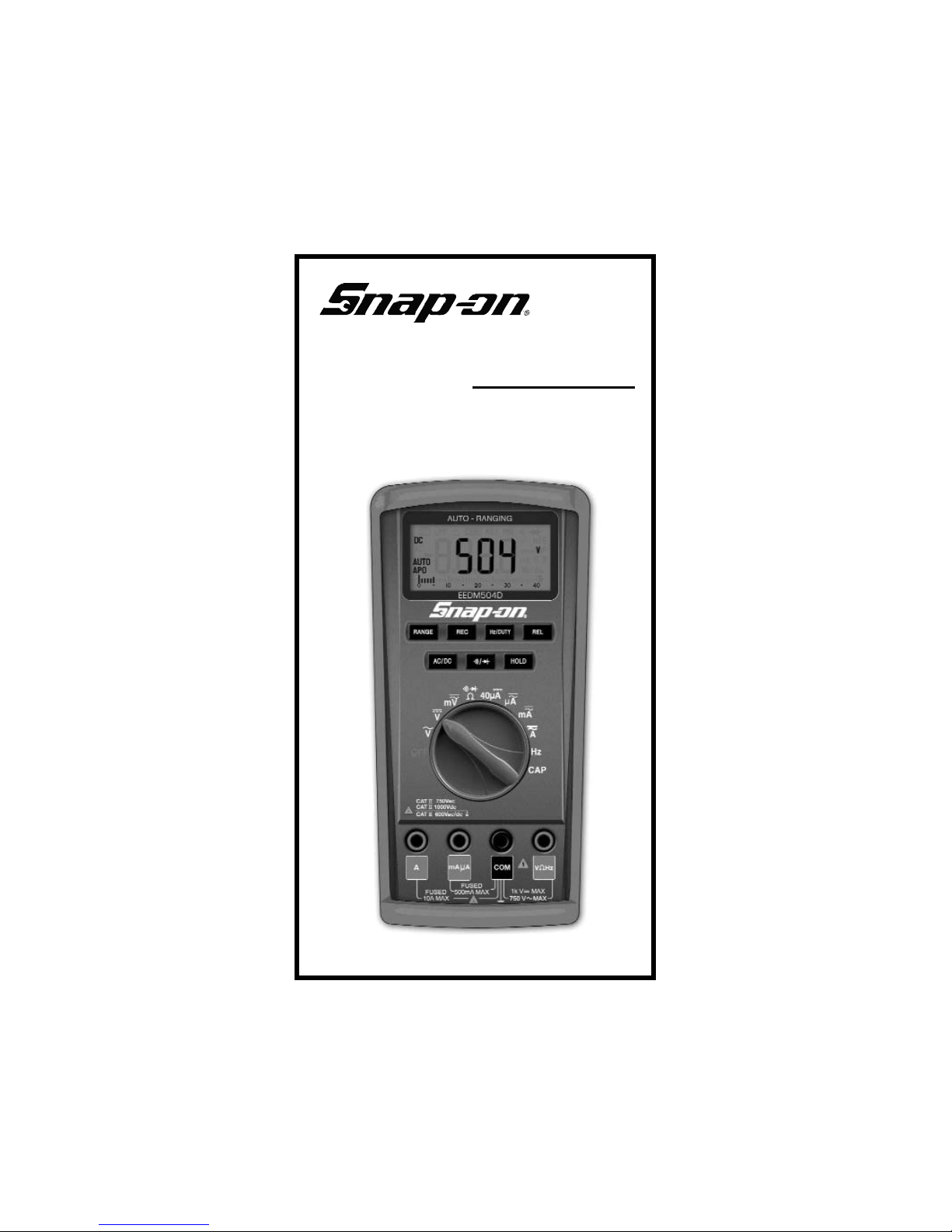
EEDM504D
Digital Multimeter
Instruction Manual
Page 2

2 3
A. INTRODUCTION
1. Congratulations!!
Thank you for purchasing Snap-on brand products. The
meter is easy to use and is built to last. It is backed by a
7 year limited warranty. Please remember to complete and
return your product warranty registration card.
2. Product Description
The EEDM504D is a hand held autoranging DMM. The
EEDM504D measures ACV, DCV, ACA, DCA, Resistance,
Frequency, Duty Cycle, Diodes and Continuity.
The EEDM504D also features:
• REC Records Min/Max readings during
specified measurement intervals.
• RANGE Allows the user to manually range the
EEDM504D instead of autoranging.
• HOLD Holds the reading on the display for
easy viewing.
• REL Displays the value as a difference to
a reference value
• AUTO OFF Preserves battery life.
The EEDM504D comes complete with the following
accessories:
EEDM504D Instrument
Zippered Vinyl Carrying Case
Rubber Boot
Test Lead Set
Instruction Manual
TABLE OF CONTENTS
A. INTRODUCTION
1. Congratulations . . . . . . . . . . . . . . . . . .3
2. Product Description . . . . . . . . . . . . . . .3
3. EC Declaration of Conformity . . . . . . . .4
B. SAFETY CONSIDERATIONS . . . . . . . . . . . . .5
C. TECHNICAL DATA
1. Features and Benefits . . . . . . . . . . . . . .6
2. Product Applications . . . . . . . . . . . . . .7
3. Specifications . . . . . . . . . . . . . . . . .8-10
D. MEASUREMENT TECHNIQUES
1. Controls and Functions . . . . . . . . . . .11
a) Push Buttons . . . . . . . . . . . .11
b) Rotary Switch . . . . . . . . . . . .12
c) Input Jacks . . . . . . . . . . . . . .12
d) Disable Auto Power Off . . . .12
2. Step by Step Procedures:
a) Measuring DC Volts . . . . . . .13
b) Measuring AC Volts . . . . . . .14
c) Measuring DC Amps . . . . . .15
d) Measuring AC Amps . . . . . .16
e) Measuring Resistance . . . . .17
f) Measuring Diodes . . . . . . . .18
g) Continuity Buzzer . . . . . . . . .19
h) Measuring Capacitance . . . .20
i) Measuring Frequency . . . . . .21
j) Record Mode . . . . . . . . . . . .22
k) Relative Mode . . . . . . . . . . .22
F. MAINTENANCE
1. Testing Fuses in Circuit . . . . . . . . . . . .23
2. Fuse Replacement . . . . . . . . . . . . . . .23
3. Battery Replacement . . . . . . . . . . . . . .24
4. Cleaning Your Meter . . . . . . . . . . . . . .25
G. TROUBLE SHOOTING GUIDE . . . . . . . . . . .25
Page 3
5
B. SAFETY CONSIDERATIONS
WARNING
: Please follow manufacturers test
procedures whenever possible. Do not attempt to
measure unknown voltages or components until a
complete understanding of the circuit is obtained.
Read instructions before operating:
Be sure these instructions accompany the tool when
passed from one user to a new or inexperienced user.
Equipment is used in a manner not specified by the
manufacturer, the protection provided by the
equipment may be impaired.
GENERAL GUIDELINES
AL
WAYS
• Test the EEDM504D before using it to make sure
it is operating properly.
• Inspect the test leads before using to make sure
there are no breaks or shorts.
• Double check all connections before testing.
• Have someone check on you periodically if
working alone.
• Have complete understanding of circuit being
measured.
• Disconnect power to circuit then, connect test
leads to the EEDM504D, then to circuit being
measured.
NEVER
• Attempt to measure unknown high voltages.
• Attempt to measure current with the meter in
parallel to the circuit.
• Connect the test leads to a live circuit before
setting up the instrument.
• Touch any exposed metal part of the test lead
assembly.
4
3. EC Declaration of Conformity
This is to certify that model EEDM504D conforms to the
protection requirements of the council directive
89/336/EEC, in the approximation of laws of the member
states relating to Electromagnetic compatibility and
73/23/EEC, The Low Voltage Directive by application of the
following standards:
EN61326 : 1997 + A1 + A2 : 2001
EN61010-1 :2001 Safety Standard
To ensure conformity with these standards, this instrument
must be operated in accordance with the instructions and
specifications given in this manual.
CAUTION:
Even though this instrument complies with the
immunity standards, the accuracy can be affected by strong radio emissions not covered in the
above standards. Sources such as hand held
radio transceivers, radio and TV transmitters,
vehicle radios and cellular phones generate
electromagnetic radiation that could be induced
into the test leads of this instrument. Care
should be taken to avoid such situations or
alternatively, check to make sure that the
instrument is not being influenced by these
emissions.
Page 4

76
INTERNATIONAL SYMBOLS
DANGEROUS VOLTAGE
AC (ALTERNATING CURRENT)
DC (DIRECT CURRENT)
REFER TO INSTRUCTION MANUAL
GROUND
FUSE
DOUBLE INSULATION
C. TECHNICAL DATA
1. Features and Benefits
Agency Approval Meets CE and IEC 61010-1 require-
ments. UL Listed to U.S. and Canadian
Safety Standards.
Auto Power OFF Active when APO is on the left side of
the LCD display. Instrument automatically powers off after 15 minutes of
inactivity. You must return the rotary
switch to the OFF position to restart
the meter.
Record Mode Records Min/Max values.
Relative Mode Displays
Range Allows you to either manual range or
use auto range to select the appropriate range.
7 Year Covered by a standard 7 year warranty.
Warranty
2. Product Applications
Perform the following tests and/or measurements
with the TPI EEDM504D and the appropriate function:
HVAC/R
FUNCTION
DCmV • Thermocouples in furnaces or gas
applications.
ACA • Heat anticipator current in thermostats.
ACV • Line voltage.
ACV or DCV • Control circuit voltage.
DCµA • Flame safeguard control current.
OHMS • Heating element resistance (continuity).
OHMS • Compressor winding resistance.
OHMS • Contactor and relay coil resistance.
OHMS • Continuity of wiring.
ELECTRICAL
ACV • Measure line voltage.
OHMS • Continuity of circuit breaker.
DCV • Voltage of direct drive DC motors.
AUTOMOTIVE
DCV • Battery and circuit voltage.
OHMS • Continuity of wires and fuses.
ACV • ABS brake sensors.
DCmA • Circuit current draw
Page 5

8
3. Specifications
IEC 61010-1 Over Voltage:
CAT II - 750Vac/1000Vdc
CAT III - 600Vac/dc
Pollution Degree 2
a. DCV
Range Resolution Accuracy Impedance
40mV 0.01mV
400mV 0.1mV
4V 0.001V ±(0.5% + 2 digits) 10MW
40V 0.01V
400V 0.1V
1000V 1V
b. ACV
Range Resolution Accuracy Impedance
40mV 0.01mV ±(1.5% + 5 digits)
400mV 0.1mV
4V 0.001V
40V 0.01V ±(0.75% +5 digits) 10MW
400V 0.1V
750V 1V ±(1.0% + 5 digits)
c. DCA
Range Resolution Accuracy Overload Protection
40µA 0.01µA ±(0.8% +2 digits)
400µA 0.1µA Fuse
4mA 0.001mA ±(0.8% +5 digits) 0.5Amp/600V
40mA 0.01mA
400mA 0.1mA
4A 0.001A ±(1.2% +5 digits) Fuse
10A 0.01A 10Amp/600V
9
UL61010-1
*Warning: Use only correct size, voltage and current rated fuses.
Test Leads: Use only correct type and overvoltage category rating.
d
d. ACA
Range Resolution Accuracy Overload Protection
400µA 0.1µA Fuse
4000µA 1µA ±(1.2% +5 digits) 0.5Amp/600V
40mA 0.01mA
400mA 0.1mA
4A 0.001A ±(1.5% +10 digits) Fuse
10A 0.01A 10Amp/600V
e. OHM (Resistance,W)
Range Resolution Accuracy Overload Protection
400W 0.1W ±(1.0% +5 digits) 600V DC or
4kW 0.001kW AC Peak
40kW 0.01kW ±(0.5% +3 digits)
400kW 0.1kW
4MW 0.001MW ±(1.0% +3 digits)
40MW 0.01MW ±(1.5% +10 digits)
g. Duty Cycle / Hz
Range
0.1 ~99.9% (0.5Hz to 500kHz, Width > 2uS)
Accuracy
((0.1% + 0.05% / kHz) +1 Count
h. Diode Test
Test Voltage Max Test Current Over Load Protection
2.7V Approx. 1mA 600 V DC or Peak AC
i. Continuity Buzzer
Test Voltage Threshold Over Load Protection
0.4 ~ 0.6V < 30W 600 V DC or Peak AC
UL61010-1
CAT II 750Vac/1000Vdc
CAT III 600Vac/dc
Page 6

11
Push
Buttons
LCD
Display
Rotary
Switch
Input
Jacks
10
j. Capacitance
Range Resolution Accuracy Overload Protection
40nF 0.01nF 600V DC or
400nF 0.1nF AC Peak
4uF 0.001nF ±(3.0% +10 digits)
40uF 0.01uF
400uF 0.1uF
4000uF 1uF ±(7.0% +10 digits)
k. Frequency (Hz)
Range Resolution Accuracy Overload Protection
10Hz 0.01Hz 600V DC or
100Hz 0.1Hz AC Peak
1KHz 0.001KHz ±(0.05% +3 digits)
10KHz 0.01KHz
100KHz 0.1KHz
1MHz 0.001MHz
10MHz 0.01MHz
l. General Specifications
Max. Volt. between 1000V
any Input and Ground
Fuse Protection mA: 0.5Amp/600VAC A: 10Amp/600VAC
Display Type 4,000 Count, 2 times per second update
Operating Temp. 0° to 40°C (32° to 104°F)
Storage Temp. -10° to 50°C (14° to 122°F)
Relative Humidity 0% to 80%
Power Supply 2 Each 1.5 Volt “AA” Batteries
Battery Life 200 hrs. Typical
Size (H x L x W) 1.3in x 3.4in x 7.4in (33mm x 86mm x 187mm)
Weight 340g (12oz)
D. MEASUREMENT TECHNIQUES
1. Controls and Functions:
a. Push Buttons
Activates manual ranging. Hold in for 3 seconds
to return to autorange.
Activates the Min/Max mode. APO (Auto Power
Off) is disabled in this function. Hold in for 3
seconds to deactivate.
Toggles the ACV or ACA measurement mode to
Hz or Duty Cycle mode.
Displays value as a difference of reference value.
Toggles between AC or DC on the mV function
and all current functions.
Toggles between continuity buzzer or diode test
on the resistance function.
Holds the reading on the display until the button
is pushed a second time.
RANGE
REC
Hz/DUTY
REL
AC/DC
/
HOLD
Page 7

1312
2. Step by Step Procedures:
a. MEASURING DC VOLTS
CAUTION!
Do not attempt to make a voltage measurement if
a test lead is plugged in the A or µmA input jack.
Instrument damage and/or personal injury may
result.
W
ARNING!
Do not attempt to make a voltage measurement of
more than 1000V or of a voltage level that is
unknown.
Instrument set-up:
FUNCTION BLACK RED MINIMUM MAXIMUM
TEST LEAD TEST LEAD READING READING
mV COM VWHz 0.1mV 400.0mV
V COM VWHz 0.001V 1000V
Measurement Procedure:
1. Disconnect power to the circuit to be measured.
2. Plug the black test lead into the COM input jack.
3 Plug red test lead into the VWHz input jack.
4. Set rotary switch to either the or range,
depending on the voltage to be measured.
5. Connect the test leads to the circuit to be measured.
6. Reconnect power to the circuit to be measured.
7. Read the voltage on the EEDM504D.
Optional Functions:
b. Rotary Switch
OFF Turns the EEDM504D off.
Function for measuring AC voltage (ACV).
Function for measuring DC voltage (DCV).
Function for measuring AC/DC millivolts (mV).
Funtion for measuring resistance, diode testing
and continuity buzzer
40 Function for measuring up to 40 DC micoamps
(uA)
Function for measuring up to 4000 AC/DC
microamps.
Function for measuring up to 400 AC/DC
milliamps.
Function for measuring up to 10 AC/DC amps
Hz Function for measuring Frequency
CAP Function for measuring Capacitance
c. Input Jacks
VWHz Red test lead connection for all Volt, Ohm,
Frequency and Capacitance functions.
COM Black test lead connection for all functions.
uAmA Red test lead connection for current
measurements on the uA and mA functions.
A Red test lead connection for current
measurements on the A function.
d. Disable Auto Power Off (APO)
With the rotary switch in the OFF position Press and
hold down the AC/DC push button while turning the
instrument on.
RANGE
REC
REL
HOLD
Manually select the appropriate range.
Activate MIN/MAX record mode (page 22).
Activate REL mode (page 22).
Freeze the reading on the LCD.
Page 8

1514
c. MEASURING DC AMPS
CAUTION!
Do not attempt to make a current measurement with
the test leads connected in parallel with circuit to be
tested. Test leads must be connected in series with
the circuit.
W
ARNING!
Do not attempt to make a current measurement of
circuits with more than 600V present. Instrument
damage and /or personal injury may result.
Instrument set-up:
FUNCTION BLACK RED MINIMUM MAXIMUM
TEST LEAD TEST LEAD READING READING
40µA COM µAmA 0.01µA 40µA
µA COM µAmA 0.1µA 4000µA
mA COM µAmA 0.01mA 400mA
10A COM A 0.001A 10.00A
Measurement Procedure:
1. Disconnect power to circuit to be measured.
2. Plug the black test lead into the COM input jack.
3. Plug the red test lead into the µAmA or A input jack
depending on the value of current to be measured.
4. Set the rotary switch to the 40µA, µA, mA, or A
function.
5. Connect test leads in series to circuit to be measured.
6. Reconnect power to the circuit to be measured.
7. Read the current on the EEDM504D.
Optional Functions:
b. MEASURING AC VOLTS
CAUTION!
Do not attempt to make a voltage measurement if a
test lead is plugged in the A or µmA input jack.
Instrument damage and/or personal injury may
result.
W
ARNING!
Do not attempt to make a voltage measurement of
more than 750V or of a voltage level that is
unknown.
Instrument set-up:
FUNCTION BLACK RED MINIMUM MAXIMUM
TEST LEAD TEST LEAD READING READING
COM VWHz 0.001V 750V
Measurement Procedure:
1. Disconnect power to the circuit to be measured.
2. Plug the black test lead into the COM input jack.
3. Plug the red test lead into the VWHz input jack.
4. Set the rotary switch to the function depending on
the voltage to be measured.
5. Connect the test leads to the circuit to be measured.
6. Reconnect power to the circuit to be measured.
7. Read the voltage on the EEDM504D.
Optional Functions:
RANGE
REC
REL
HOLD
Manually select the appropriate range.
Activate MIN/MAX record mode (page 22).
Scroll between Hz, Duty, and Volts.
Activate REL mode (page 22).
Freeze the reading on the LCD.
Hz/DUTY
RANGE
REC
REL
HOLD
Manually select the appropriate range.
Activate MIN/MAX record mode (page 22).
Activate REL mode (page 22).
Freeze the reading on the LCD.
Page 9

1716
e. MEASURING RESISTANCE
WARNING!
Do not attempt to make resistance measurements with
circuit energized. For best results, remove the resistor
completely from the circuit before attempting to
measure it.
NOTE:
To make accurate low ohm measurements, short the
ends of the test leads together and press the REL
pushbutton. This value will automatically be deducted
from your reading.
Instrument set-up:
FUNCTION BLACK RED MINIMUM MAXIMUM
TEST LEAD TEST LEAD READING READING
W COM VWHz 0.1W 40.00MW
Measurement Procedure:
1. Disconnect power to the circuit to be measured.
2. Plug the black test lead into the COM input jack.
3. Plug the red test lead into the VWHz input jack.
4. Set the rotary switch on the EEDM504D to the W
function.
5. Connect the test leads to the circuit to be measured.
6. Read the resistance value on the EEDM504D.
Optional Functions:
d. MEASURING AC AMPS
CAUTION!
Do not attempt to make a current measurement
with the test leads connected in parallel with the
circuit to be tested. Test leads must be connected
in series with the circuit.
W
ARNING!
Do not attempt to make a current measurement of
circuits with more than 600V present. Instrument
damage and /or personal injury may result.
Instrument set-up:
FUNCTION BLACK RED MINIMUM MAXIMUM
TEST LEAD TEST LEAD READING READING
µA COM µAmA 0.1µA 4000µA
mA COM µAmA 0.01mA 400mA
10A COM A 0.001A 10.00A
Measurement Procedure:
1. Disconnect power to the circuit to be measured.
2. Plug the black test lead into the COM input jack.
3. Plug the red test lead into the µAmA or A input jack
depending on the value of current to be measured..
4. Set the rotary switch to the µA, mA or A function.
5. Press the AC/DC pushbutton to set to AC mode.
6. Connect test leads in series to circuit to be measured.
7. Reconnect power to the circuit to be measured.
8. Read the current on the EEDM504D.
Optional Functions:
RANGE
REC
REL
HOLD
Manually select the appropriate range.
Activate MIN/MAX record mode (page 22).
Scroll between Hz, Duty, and Volts.
Activate REL mode (page 22).
Freeze the reading on the LCD.
Hz/DUTY
RANGE
REC
REL
HOLD
Manually select the appropriate range.
Activate MIN/MAX record mode (page 22).
Activate REL mode (page 22).
Freeze the reading on the LCD.
Page 10

1918
g. CONTINUITY BUZZER
WARNING!
Do not attempt to make continuity measurements
with circuit energized.
Instrument set-up:
FUNCTION BLACK RED
TEST LEAD TEST LEAD
COM VWHz
Measurement Procedure:
1. Disconnect power to the circuit to be measured.
2. Plug the black test lead into the COM input jack.
3. Plug the red test lead into the VWHz input jack.
4. Set the rotary switch to the function.
5. Press yellow push button to activate continuity buzzer.
6. Connect the test leads to the circuit to be measured.
7. Listen for the buzzer to confirm continuity.
f. MEASURING DIODES
CAUTION!
Do not attempt to make diode measurements with
circuit energized. The only way to accurately test
a diode is to remove it completely from the circuit
before attempting to measure it.
Instrument set-up:
FUNCTION BLACK RED MINIMUM MAXIMUM
TEST LEAD TEST LEAD READING READING
COM VWHz 0.001V 2.000V
Measurement Procedure:
1. Disconnect power to the circuit to be measured.
2. Plug the black test lead into the COM input jack.
3. Plug the red test lead into the VWHz input jack.
4. Set the rotary switch to the function.
5. Connect black test lead to the banded end of the diode
and the red test lead to the non-banded end of the
diode.
6. Reading on the display should be between
0.5 and 0.8 volts.
7. Reverse test lead connections in 5 above.
8. Reading on the display should be OFL (Overload).
NOTE: If diode reads 0 in both directions, diode is shorted. If diode reads OFL in both directions, diode is open
Page 11

2120
h. MEASURING CAPACITANCE
CAUTION!
Disconnect power to the circuit(s) to be
measured. Discharge the capacitorto be
measured completely before attempting to
measure.
Instrument set-up:
FUNCTION BLACK RED MINIMUM MAXIMUM
TEST LEAD TEST LEAD READING READING
CAP COM VWHz 0.01nF 4000uF
Measurement Procedure:
1. Disconnect power and discharge the capacitor to be
measured.
2. Plug the black test lead into the COM input jack.
3. Plug the red test lead into the VWHz input jack.
4. Set the rotary switch to the CAP function.
5. Connect the test leads to the capacitor to be
measured.
6. Read the capacitance on the EEDM504D.
Optional Functions:
i. MEASURING FREQUENCY
CAUTION!
Do not attempt to make a frequency
measurement if a test lead is plugged in the
A or µmA input jack. Instrument damage
and/or personal injury may result.
W
ARNING!
Never attempt a frequency measurement
with a voltage source reater than 600V
Instrument set-up:
FUNCTION BLACK RED MINIMUM MAXIMUM
TEST LEAD TEST LEAD READING READING
Hz COM VWHz 0.001Hz 10MHz
Measurement Procedure:
1. Disconnect power to the circuit to be measured.
2. Plug the black test lead into the COM input jack.
3. Plug the red test lead into the VWHz input jack.
4. Set the rotary switch to the Hz function.
5. Connect the test leads to the circuit to be measured.
6. Reconnect power to the circuit to be measured.
7. Read the frequency on the EEDM504D.
Optional Functions:
HOLD
Scroll between Hz and Duty %.
Freeze the reading on the LCD.
Hz/DUTY
REL
HOLD
Activate REL mode (page 22).
Freeze the reading on the LCD.
Page 12

2322
F. MAINTENANCE
1. Testing Fuses In Circuit: Both the A and mAµA input
jacks are fuse protected. The fuses can be tested
without removing them from the instrument as
follows:
a. Set the EEDM504D to the diode test function.
b. Insert the red test lead into the V input jack.
c. Touch the tip of the red test lead into the A
input jack making sure you contact the metal.
d. If the display reads any number, the fuse is good.
If the display reads .OL, the fuse is open and
must be replaced.
e. Repeat the same procedure for the uAmA input
jack.
2. Fuse Replacement: Both the A and mAµA input jacks
are fuse protected. If either do not function, replace
fuse as follows:
a. Disconnect and remove all test leads from live
circuits and from the EEDM504D.
b. Remove EEDM504D from protective boot.
c. Remove the three screws from the lower back of
housing holding the compartment cover in place.
d. Remove the compartment cover.
e. Remove the old fuse(s) and replace it with new
fuse(s).
f. Reassemble the instrument in reverse order
from above.
j. RECORD MODE
The record mode saves minimum (MIN) and maximum
(MAX) values measured for a series of reading. Activate
the function as follows:
1. Depress the REC button on the EEDM504D.
2. The EEDM504D will immediately start to record
MIN/MAX values. REC will be on the LCD to
show record mode has been activated. The
reading on the LCD will be the actual reading.
The EEDM504D will give a confirmation beep
every time a new value is recorded.
3. Press the REC button a second time and the
MIN reading will be displayed.
4. Press the REC button a third time and the MAX
reading will be displayed on the LCD.
5. To terminate the record mode, hold the REC
button down for approximately 2 seconds or
turn the rotary switch to a different function.
k. RELATIVE MODE
The Relative mode compares readings to a known value
and displays it as a difference to that value on the LCD.
1. Measure the known value on the EEDM504D
and press the REL button, the LCD will display
zero.
2. Measure next device for comparison.
3. The LCD will display the difference between the
new device and the stored reference value.
5. To terminate the Relative mode, hold the REL
button down for approximately 2 seconds or
turn the rotary switch to a different function.
Page 13

2524
G. TROUBLE SHOOTING GUIDE
Problem Probable Causes
Does not power up
• Dead or defective battery
• Broken wire from battery
snap to PCB
Won’t display current readings
• Open fuse
• Open test lead
• Improperly connected to
circuit under test
3. Cleaning Your Meter: The EEDM504D can be wiped
clean with a damp cloth and mild detergent. Do not
submerse in water.
3. Battery Replacement: The EEDM504D will display a
battery symbol in the upper left corner of the LCD when
the two internal 1.5 Volt “AAA” batteries need
replacement. Batteries are replaced as follows:
a. Disconnect and remove all test leads from live
circuits and from the EEDM504D.
b. Remove EEDM504D from protective boot.
c. Remove the three screws from the lower back of
housing holding the compartment cover in place.
d. Remove the compartment cover.
e. Remove old batteries and replace with new
batteries.
f. Reassemble instrument in reverse order from
above.
10 Amp
Fuse
0.5 Amp
Fuse
Battery/Fuse Compartment
1.5 volt “AAA”
Alkaline Battery
(2 each)
Page 14

2726
Notes:
Notes:
Page 15

Snap-on is a trademark of Snap-on Incorporated.
©2008 Snap-on Incorporated. All Rights Reserved
Snap-on, 2801 80th St., Kenosha, WI 53143
www.snapon.com
ZEEDM504D User’s Manual ©
2008
Printed in South Korea
The information, specifications and illustrations in this manual
are based on the latest information available at the time of
printing. Snap-on Tools Company, LLC reserves the right to
make changes at any time without notice.
 Loading...