

Page 1
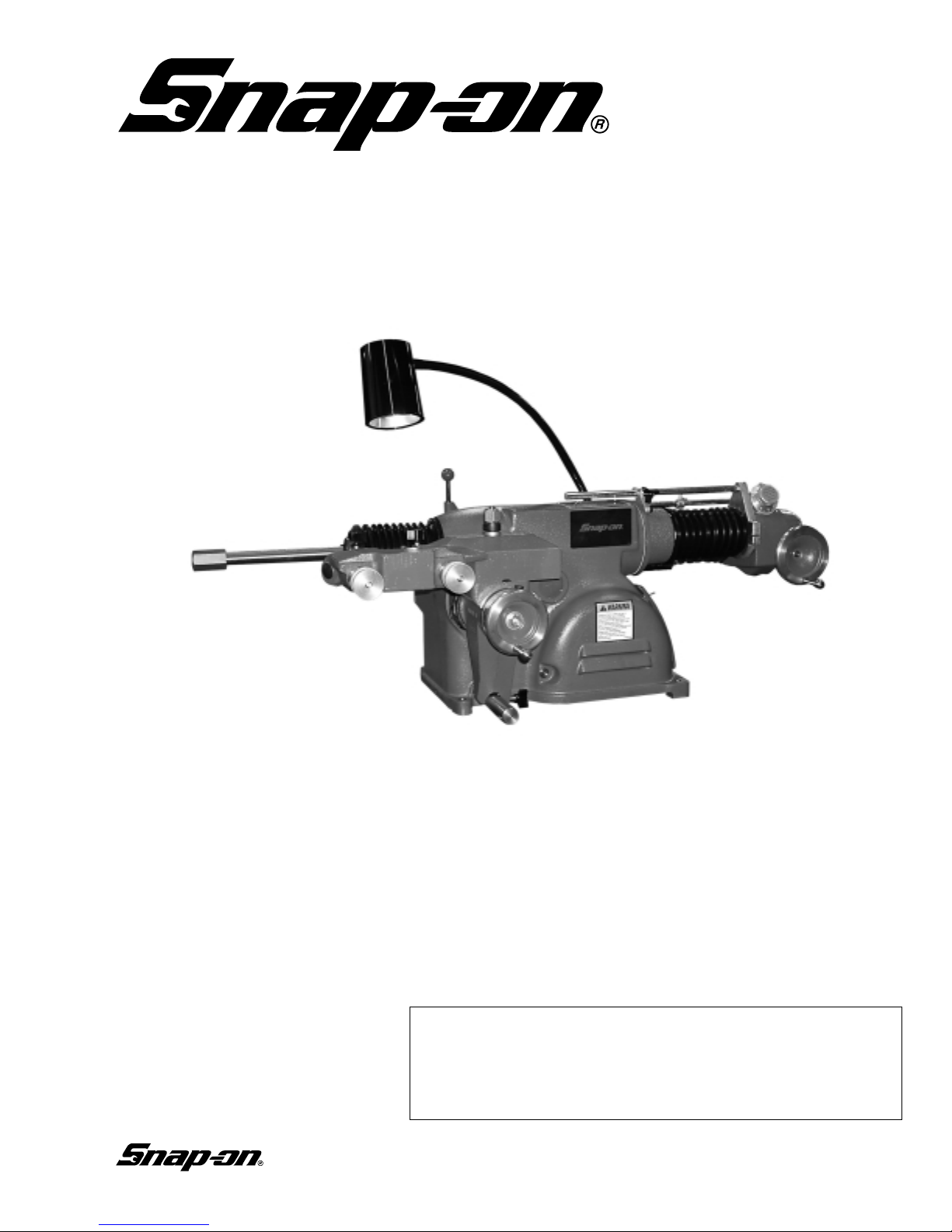
EEBR312A
Brake Lathe
Installation Instructions
Operating Instructions
Safety Instructions
Maintenance Instructions
READ these instructions before placing unit in
service. KEEP these and other materials delivered
with the unit in a binder near the machine for
ease of reference by supervisors and operators.
Page 2

2 • Snap-on
READ ALL INSTRUCTIONS
When using your garage equipment, basic safety precau-
tions should always be followed, including the following:
1. Keep guards in place and in working order.
2. Remove adjusting keys and wrenches from the tool
before turning it on. Make this a habit.
3. Keep work area clean and well lighted. Cluttered areas
and benches invite accidents.
4.To reduce the risk of fire, do not operate equipment in the
vicinity of open containers of flammable liquids (gasoline).
5. Adequate ventilation should be provided when working
on operating internal combustion engines.
6. Care must be taken as burns can occur from touching
hot parts.
7. Do not operate equipment with a damaged cord or if the
equipment has been dropped or damaged—until it has been
examined by a qualified serviceman.
8. If an extension cord is necessary, a cord with a current
rating equal to or more than that of the equipment should be
used. Cords rated for less current than the equipment may
overheat. Care should be taken to arrange the cord so that it
will not be tripped over or pulled.
9. To reduce the risk of electric shock, do not use on wet
surfaces or expose to rain.
10. Keep children away. All bystanders should be kept completely away from the work area.
11. Make the workshop kid-proof. Use padlocks and master switches, and remove starter keys.
12. Don’t force a tool. It will do the job better and safer at
the rate for which it was designed.
13. Use the right tool. Don’t force a tool or an attachment
to do a job for which it was not designed.
14. Dress properly. Keep hair, loose clothing, neckties,
shop rags, jewelry, fingers, and all parts of body away from
moving parts. Non-slip footwear is recommended.
15. ALWAYS WEAR SAFETY GLASSES. Everyday eyeglasses only have impact resistant lenses, they are NOT
safety glasses. Safety glasses, goggles, or a face shield will
help protect the operator from injury. Use a face shield and
dust mask during dusty operations.
16. Secure the work properly to the unit for setup and tool
bit positioning. Do not attempt to hold a drum or rotor steady
on the arbor with your hands. Both hands must be free to
operate unit.
17. Don’t overreach. Keep proper footing and balance at all
times when lathe is in operation or when working around the
unit.
18. Maintain tools with care. Keep tools sharp and clean for
best and safest performance. Follow instructions for lubricating and changing accessories.
19. Remove power from the unit and disconnect tools
before servicing and when changing accessories such as
blades, bits, cutters, etc. Follow lock-out and tag-out procedures as required.
20. Avoid unintentional starting. Make sure the switch is in
the OFF (O) position before plugging the machine in or performing any maintenance or service work.
21. Use of improper accessories may cause risk of injury to
operator or bystanders. Use only as described in this manual.
Use only manufacturer’s recommended attachments.
22. Never stand or lean on a lathe. Serious injury could
occur if the lathe is tipped or if the cutting tool is unintentionally contacted.
23. Check damaged parts carefully. Before further use of
the lathe, a guard or other part that is damaged should be
carefully checked. Immediately replace all damaged, missing,
or non-functional parts. Check for alignment of moving parts,
binding of moving parts, breakage of parts, mounting, and any
other conditions that may affect operation. Guards and other
parts that are damaged should be properly repaired or
replaced before lathe is used again.
24. Always feed the work into a blade or cutter and against
the direction of rotation. Cutters and tool bits are designed to
cut from the inside of a drum or rotor to the outer edge. Do
not attempt to cut from the outside edge in to the center.
25. Never leave tools running unattended. Turn the power
off. Don’t leave the tool until it comes to a complete stop.
26. Never use compressed air to blow the tool clean. Chips
and dust may be driven between machined parts and into
bearings, causing undue wear. They may also contact persons
in the area causing personal injury.
27. Operate the lathe in the proper environment. The lathe
incorporates parts such as snap switches and power receptacles which tend to produce arcs or sparks. Therefore, when
located in a garage,the unit should be in a room or enclosure
provided for the purpose, or should be at least 18” or more
above the floor to minimize the risk of igniting fuel vapors.
Before operating the lathe, review the warning information on the lathe and the cautions, warnings and dangers in this manual. Also review the following general safety instructions. Failure to follow safety instructions could result in personal injury to
operator or bystanders and damage to the lathe or personal property.
IMPORTANT SAFETY INSTRUCTIONS
SAVE THESE INSTRUCTIONS
Page 3

Snap-on • 3
Brake Lathes
Table of Contents
Important Safety Instructions . . . . . . . . . . .2
Safety Notices and Decals . . . . . . . . . . . . . .4
Warnings . . . . . . . . . . . . . . . . . . . . . . . . . . . . .4
Cautions and Dangers . . . . . . . . . . . . . . . . . . . . . .4
Owner’s Responsibility . . . . . . . . . . . . . . . . .5
Definitions of Hazard Levels . . . . . . . . . . . . .5
Before You Begin . . . . . . . . . . . . . . . . . . . . . .6
Receiving . . . . . . . . . . . . . . . . . . . . . . . . . . . . . . . .6
Electrical Requirements . . . . . . . . . . . . . . . . . . . . .6
Installation . . . . . . . . . . . . . . . . . . . . . . . . . . . . . . .6
Operating Specifications . . . . . . . . . . . . . . . . . . . .7
Principle Operating Parts . . . . . . . . . . . . . . . . . . . .8
Arbor Installation . . . . . . . . . . . . . . . . . . . . . . . . . .9
Adapters . . . . . . . . . . . . . . . . . . . . . . . . . . . . . . . .9
Basic Operation . . . . . . . . . . . . . . . . . . . . . . .9
Spindle . . . . . . . . . . . . . . . . . . . . . . . . . . . . . . . . . .9
Spindle Feed . . . . . . . . . . . . . . . . . . . . . . . . . . . . .9
Spindle Speed . . . . . . . . . . . . . . . . . . . . . . . . . . . .9
Spindle Speed Adjustment . . . . . . . . . . . . . . . . . .9
Cross Feed . . . . . . . . . . . . . . . . . . . . . . . . . . . .9-10
V-Belt Tension and Adjustment . . . . . . . . . . . . . .10
Basic Operation of Handwheels . . . . . . . . . . . . .10
Reconditioning Brake Drums . . . . . . . . . . .11
Preparation . . . . . . . . . . . . . . . . . . . . . . . . . . . . . .11
Mounting Drums . . . . . . . . . . . . . . . . . . . . . . .11-13
Typical Drum Mounting Configurations . . . . . . . .12
Reconditioning Disc Brake Rotors . . . . . . .14
Preparation . . . . . . . . . . . . . . . . . . . . . . . . . . . . . .14
Rotor Mounting . . . . . . . . . . . . . . . . . . . . . . . . . .14
Model 6950 Twin Cutter . . . . . . . . . . . . . . . . . . .14
Typical Rotor Mounting Configurations . . . . . . . .15
Set Up and Reconditioning Rotors . . . . . . . . .16-18
Maintenance and Service . . . . . . . . . . .18-19
Oiling . . . . . . . . . . . . . . . . . . . . . . . . . . . . . . . .18-19
Cleaning . . . . . . . . . . . . . . . . . . . . . . . . . . . . . . . .19
Care of Arbors and Adapters . . . . . . . . . . . . . . . .19
Shear Gear Replacement . . . . . . . . . . . . . . . . . . .19
Page 4
4 • Snap-on
Brake Lathes
Safety Notices and
Decals
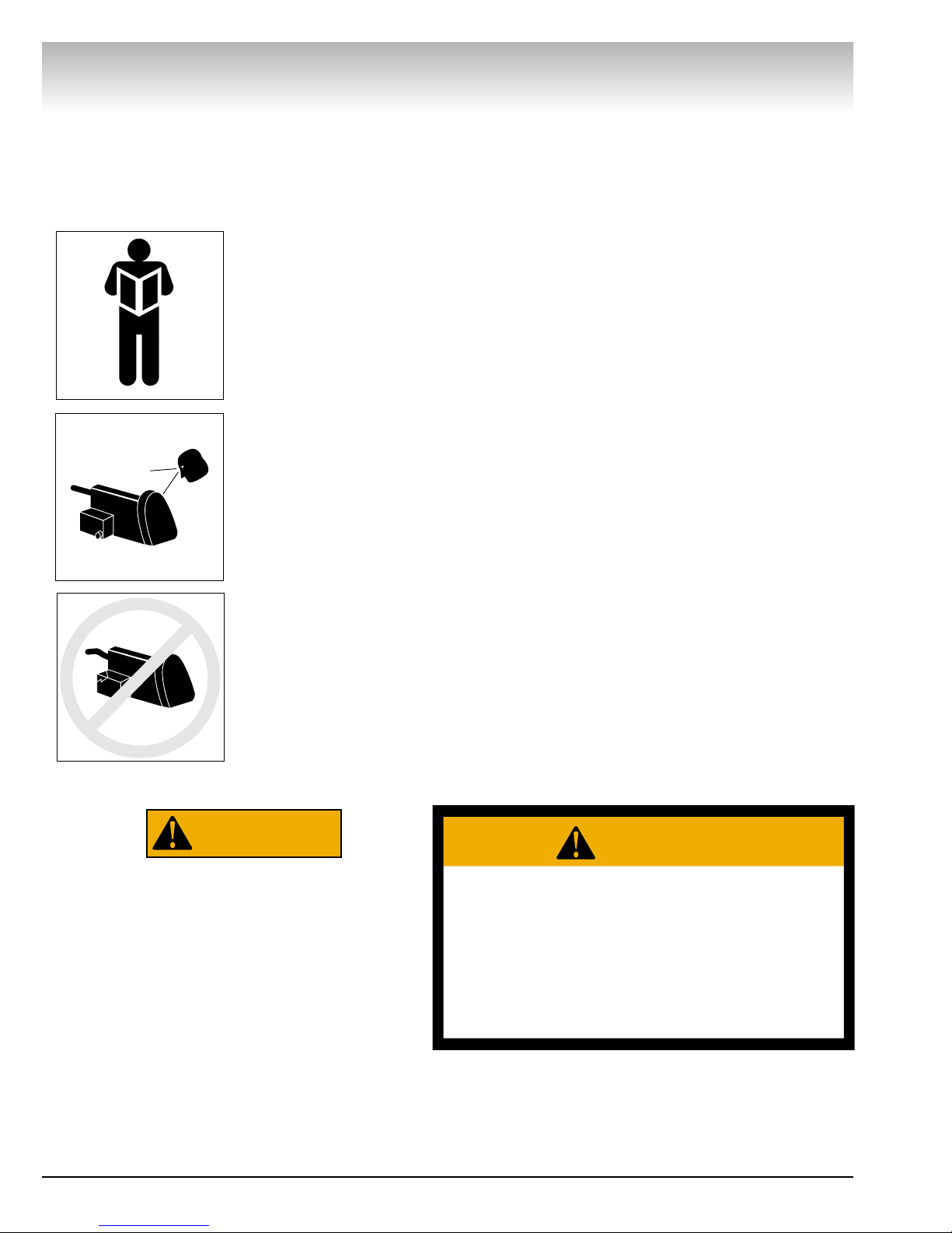
For your safety, and the safety of others, read and
understand all of the safety notices and decals included here and on the unit.
Read entire manual
before installing,
operating, or servicing this equipment.
Proper maintenance
and inspection is
necessary for safe
operation.
Do not operate a
damaged lathe.
Failure to follow danger, warning, and caution instructions may lead to serious personal injury or death to operator or
bystander or damage to property. Do not
operate this machine until you read and
understand all the dangers, warnings and
cautions in this manual.
Warnings
This equipment incorporates parts such as snap
switches and power receptacles which tend to produce arcs or sparks. Therefore, when located in a service facility, the unit should be in a room or enclosure
provided for the purpose, or should be at least 18” or
more above floor to minimize the risk of igniting fuel
vapors.
Cautions and Dangers
1. Eye and face protection requirements:
“Protective eye and face equipment is required
to be used where there is a reasonable
probability of injury that can be prevented by use
of such equipment.” OSHA 1910.133 (a).
Protective goggles, safety glasses, or a face
shield must be provided by the purchaser/user
and worn by the operator of the equipment.
Make sure all eye and face safety precautions are
followed by the operator(s). Keep bystanders out
of the area.
2. Do not remove any safety equipment, belt
guards, or shortcut controls or operations.
3. Make sure drums and rotors are properly and
squarely mounted before starting lathe, and that
all parts are secure.
4. Do not wear loose clothing, jewelry, or gloves
when operating or working around a lathe.
5. Do not overload the lathe. Read and understand
the lathe specifications. Overloading is poor
machine tool practice, shortens the life of the
lathe, and could cause a failure resulting in
personal injury.
WARNING
WARNING
For Your Own Safety Read Instruction
Manual Before Operating Lathe
• Wear eye protection.
• Do not wear gloves, necktie, or loose clothing.
• Tighten all locks before operating.
• Rotate workpiece before installing on faceplate.
• Risk of injury due to accidential starting.
• Do not use in an area where children may be
present.
941134
Page 5

Snap-on • 5
Brake Lathes
Owner’s Responsibility
To maintain machine and user safety, the responsibility of the owner is to read and follow these instructions:
• Follow all installation instructions.
• Make sure installation conforms to all applicable
Local, State, and Federal Codes, Rules, and
Regulations; such as State and Federal OSHA
Regulations and Electrical Codes.
• Carefully check the unit for correct initial function.
• Read and follow the safety instructions. Keep
them readily available for machine operators.
• Make certain all operators are properly trained,
know how to safely and correctly operate the
unit, and are properly supervised.
• Allow unit operation only with all parts in place
and operating safely.
• Carefully inspect the unit on a regular basis and
perform all maintenance as required.
• Service and maintain the unit only with
authorized or approved replacement parts.
• Keep all instructions permanently with the unit
and all decals/labels/notices on the unit clean and
visible.
• Do not override safety features.
Definitions of Hazard
Levels
Identify the hazard levels used in this manual with
the following definitions and signal words:
DANGER
Watch for this symbol:
It Means: Immediate hazards, which will result in
severe personal injury or death.
WARNING
Watch for this symbol:
It Means: Hazards or unsafe practices, which could
result in severe personal injury or death.
CAUTION
Watch for this symbol:
It Means: Hazards or unsafe practices, which may
result in minor personal injury or product or property
damage.
Watch for this symbol! It means BE ALERT! Your
safety, or the safety of others, is involved!
DANGER
WARNING
CAUTION
Page 6

6 • Snap-on
Brake Lathes
Before You Begin
Receiving
The shipment should be thoroughly inspected as
soon as it is received. The signed bill of lading is
acknowledgement by the carrier of receipt in good
condition of shipment covered by our invoice.
If any of the goods called for on this bill of lading are
shorted or damaged, do not accept them until the carrier makes a notation on the freight bill of the shorted
or damaged goods. Do this for your own protection.
NOTIFY THE CARRIER AT ONCE if any hidden loss or
damage is discovered after receipt and request the
carrier to make an inspection. If the carrier will not do
so, prepare a signed statement to the effect that you
have notified the carrier (on a specific date) and that
the carrier has failed to comply with your request.
IT IS DIFFICULT TO COLLECT FOR LOSS OR DAMAGE AFTER YOU HAVE GIVEN THE CARRIER A
CLEAR RECEIPT.
File your claim with the carrier promptly. Support
your claim with copies of the bill of lading, freight bill,
invoice, and photographs, if available.
Electrical Requirements
The lathe must be properly grounded to protect the
operator from shock. The lathe is equipped with an
approved 3-conductor cord and a 3-prong grounding
type plug to fit the proper grounding-type receptacle.
Should an extension cord be required, use 3-conductor cords with 3-prong grounding plug and 3-prong
grounding receptacle properly rated to handle this
electrical power tool only. Do not modify a cord or plug
to match a receptacle; have a qualified electrician
install an appropriate outlet to match the lathe requirements. Repair or replace any worn or damaged power
cords immediately.
Verify that the lathe plug and grounding-type receptacle match as shown in Figure 1.
Figure 1 - Power Cord Plug and Receptacle Types
Installation
1. Assemble bench according to the instructions
provided. Tighten all fasteners securely.
2. After assembly, the bench should be leveled and
may be bolted down with 3⁄8 or 7⁄16 inch bolts or lag
screws.
3. Unbolt the lathe from the shipping pallet. Lift the
lathe onto the bench.
4. Bolt the lathe to the bench with the hardware
provided. Tighten fasteners securely.
5. Remove any packing materials and protective
wrapping from the lathe and components.
6. Make sure lathe is turned off. Plug lathe into a
properly installed and grounded outlet that matches
the lathe plug.
7. Remove the shipping plug, insert the oil dipstick,
and check oil level. The lathe is shipped with the correct amount and type of oil. Add oil as necessary to
reach the correct mark on the dipstick. Use only EP80-90 gear oil. Oil level should be checked often.
Figure 2 – Check oil level
8. Clear the area and turn lathe on. Check for proper
operation (motor and spindle rotation).
Preparation for Use
1. Inspect all adapters and accessories for burrs,
nicks, or other damage.
2. Clean accessories with a vaporizing solvent.
3. Apply a light film of oil to all adapters to protect
their machined surfaces from rust. Refer to the maintenance section for more information.
115 VAC 220 VAC
Page 7

Snap-on • 7
Brake Lathes
Operating Specifications
4100
Overall lathe height 17.25” (438 mm)
Lathe shipping weight 410 lbs (186 kg)
Floor space requirements - width 48” (1219.20 mm)
Floor space requirements - deep 34.5” (901.70 mm)
Spindle to floor (mounted on optional bench) 39.375” (1000 mm)
Electrical requirements 115 VAC, 60 Hz, single-phase, fused at 20 amps
(unless otherwise specified)
Spindle motor 1 HP, 60 Hz, 115/230 VAC
Spindle travel 9.875” (251 mm)
Spindle speed
Inner groove 60 RPM
Middle groove 80 RPM
Outer groove 115 RPM
Spindle feed speed Infinitely variable
Minimum 0.002 inch per revolution (0.05 mm/rev)
Maximum 0.020 inch per revolution (0.50 mm/rev)
Cross feed speed
Fine 0.002
Course 0.010
Handwheel graduations 0.002 (0.050 mm)
Maximum brake rotor diameter* 14.5” (368.3 mm)
Maximum brake rotor thickness 1.875” (47.63 mm)
Brake drum diameter
Minimum 6” (152 mm)
Maximum 28” (711 mm)
Maximum drum depth 9.875” (251 mm)
Maximum load
1” Arbor 100 lbs. (45.36 kg)
1.875” Arbor 200 lbs. (90.72 kg)
* The no. 906936 Cross Feed Extension – increases the maximum rotor diameter to 19” (483 mm).
Page 8

8 • Snap-on
Brake Lathes
Work Light
1” Arbor
Twin Cutter
Cross Feed Lock
Cross Feed
Handwheel
Spindle Feed Handwheel
Spindle Feed Dial
Spindle Feed
Engaging Lever
Spindle Lock
Oil Dipstick
Cross Feed
Engaging Lever
Cross Feed
Gearbox
V-Belt & Speed
Adjusting Lever
Belt Tension
Adjusting Nut
ON/OFF Switch
Infimatic®Variable
Feed Gearbox
Assembly
Draw Bar
Drive Motor
Pulley Guard
Principle Operating Parts
Page 9

Snap-on • 9
Brake Lathes
Arbor Installation
The 1" arbor shipped with the lathe has been carefully matched to the lathe during final assembly and
testing. Witness marks have been etched onto the
arbor and the spindle for precise, repeatable alignment.
The witness marks must be carefully aligned when
installing the arbor (Figure 3). A true-running arbor is
essential to professional quality brake drum and rotor
reconditioning.
1. Locate the witness marks on the arbor and the
spindle.
Figure 3 – Align witness marks during arbor installation
2. Insert the arbor into the spindle making sure the
witness marks are aligned.
3. Tighten the drawbar (located at the rear of the
spindle) to pull the hardened and ground tapers of the
arbor into the matching seats in the spindle.
Adapters
Important: Although the adapters, arbor, and spindle
are made of top grade steel and are turned, hardened,
and precision ground to close tolerances, great care
should be taken in their use, handling, and storage.
Even the smallest nick, scratch, or loose chip on the
machined mating surfaces can cause incorrect rotor
mounting alignment. This will cause inaccurate
machining.
Figure 4 – Use care to avoid damaging mating surfaces
Always inspect the surface, face, and seating tapers
of each part before use. Wipe each part clean before
and after using it. Carefully correct any flaw with a fine
stone. If damage cannot be corrected, replace the
part.
Basic Operation
To completely understand drum and rotor turning
you must have a knowledge of the lathe itself.
Spindle
The spindle is a motor driven shaft that turns the
arbor upon which the brake drum or rotor is mounted.
By turning the drum and holding a cutting tool against
the inner braking surface, metal can be removed.
Do not try to move any feed levers or dials
without the drive motor running. Damage
may occur to the gear trains.
Spindle Feed
By operating the spindle feed lever, the spindle will
move the mounted brake drum to the left. This feeds
the braking surface across the cutting tool as the drum
moves away from the tool. Spindle feed may also be
done manually using the spindle feed handwheel.
Spindle feed refers to the distance the spindle is
pulled per revolution. This speed is adjustable.
Important: Spindle feed must be adjusted with the
lathe running.
1. Rotate the spindle feed dial to the desired feed
rate. The rate is adjustable to any point between
0.002" (0.05 mm) and 0.020" (0.50 mm).
Spindle Speed
Spindle speed is measured in RPMs and is
adjustable. Refer to the specifications listed on page 7
for the RPM rating of each groove on the V-belt pulley.
Spindle Speed Adjustment
This V-belt adjustment must be made with the lathe
off.
1. Release the belt tension by moving the V-belt
adjusting lever to the right (clockwise).
2. Move the belt to the pulley groove that will give
the correct spindle speed for the cut to be taken.
3. Reapply tension to the V-belt by moving the
adjusting lever back to the operating position.
Cross Feed
The cross feed draws the tool bit across the face of
a brake rotor or flywheel when the cross feed drive is
engaged. The cross feed may also be operated manually using the cross feed handwheel.
Arbor
Keep the arbor tapers and seats clean
Witness Marks
Typical Inner &Outer Adapters
Seating Tapers
Machined Surfaces
CAUTION
Page 10

10 • Snap-on
Brake Lathes
Feed speed refers to the thousandths of an inch the
cutting tools move per revolution of the spindle. The
cross feed speed is adjustable.
1. Using the 3-position lever, select Fine (0.002"
[0.05 mm]) or Coarse (0.010" [0.25 mm]). The Neutral
position is the off position (no movement). The cross
feed may also be operated manually.
V-Belt Tension and Adjustment
A loose belt can cause slippage when taking heavy
cuts. A belt that is too tight can cause vibration and
possible sub-standard finishes on machined drums
and rotors. Check and adjust belt monthly.
There should be between 1⁄4” to 1⁄2” of play in the
belt.
1. Position the v-belt speed adjusting lever to the
left (counterclockwise) to the fully engaged position.
2. Loosen the adjustment nut.
Figure 5 – Engage lever and loosen nut
3. Push in on the belt approximately 1⁄4” to 1⁄2”
(0.64 to 12.7 mm) and hold.
4. Retighten the adjusting nut.
Figure 6 – Press the belt in and tighten adjusting nut
Basic Operation of Handwheels
Clockwise rotation of the spindle feed handwheel
retracts the spindle in towards the lathe.
Clockwise rotation of the cross feed handwheel
moves the cutting tool in towards the lathe.
Figure 7 – Clockwise rotation of handwheels
Counterclockwise rotation of the spindle feed hand-
wheel extends the spindle out away from the lathe.
Counterclockwise rotation of the cross fee hand-
wheel moves the cutting tool out away from the lathe.
Figure 8 – Counterclockwise rotation of handwheels
Spindle Feed
Handwheel
Cross Feed
Handwheel
Spindle rotates when
motor is turned on.
Spindle Feed
Handwheel
Cross Feed
Handwheel
V-belt
Adjustment Nut
Speed Adjusting Lever
Push in
1
⁄
4” to
1
⁄
2”
Page 11

Snap-on • 11
Reconditioning Brake
Drums
Preparation
1. Measure the diameter of the brake drum with a
brake drum micrometer.
Figure 9 – Measure drum diameter
2. Determine if the drum will be within maximum
rebore limits after reconditioning.
Note: Most often, the DISCARD diameter is cast into
the brake drum, not the maximum machining diameter.
3. Inspect brake drum. Do not attempt to machine a
drum that is damaged or in poor condition.
Mounting Drums
1. Loosen the boring bar clamp nut and push the
boring bar all the way into the clamp.
2. Mount the drum on the arbor using the proper
adapters, cones, and spacers.
3. Wrap the drum silencer band snugly around the
drum. Be sure it covers up to the right-hand edge.
Figure 10 – Attach silencer band
Important: The spindle feed handwheel will not
operate unless the spindle feed engagement lever is
in the OFF position. Feed should only be adjusted
when the spindle is turning.
4. Position the cross slide and spindle by turning their
respective handwheels to their maximum clockwise (in)
position. Then back off the cross feed handwheel 2
complete turns and the spindle handwheel 4 complete
turns.
5. Position the boring bar by loosening the boring
bar clamp nut and sliding the boring bar inward toward
the drum until the tool bit is close to the drum.
The boring bar position is changed whenever a drum
of different diameter is machined.
The entire boring bar clamp may also be swiveled to
achieve the best cutting position.
Figure 11 – Positioning the boring bar
6. Turn the drum by hand to make sure that everything is clear.
7. Turn the lathe ON.
8. Advance the tool bit manually until it just contacts
the drum surface momentarily and makes a scratch cut.
Figure 12 – First scratch cut
9. Loosen the dial lock screw on the cross feed
handwheel and set the dial to the diameter of the
drum as measured with the micrometer. Tighten the
lock screw.
This setting will be the reference used to help deter-
mine the drum recondition diameter.
Figure 13 – Set drum diameter measurement
Brake Lathes
Arrows for reading scale
Dial
Buckle Finger
Silencer Band for Drums
First
Scratch Cut
Dial Lock
Screw
Page 12

12 • Snap-on
Brake Lathes
A
C
B
E
H
D
F
I
G
Hubless Brake Drums
A
C
B
L
K
D
F
Hubbed Brake Drums
Hubbed Brake Drums — Tapered cone adapters fit
in the bearing seats, making contact near the middle
of the bearing race whenever possible rather than near
an edge. Various adapters and spacers may be used to
fill out the shaft of the arbor.
Hubless Brake Drums — A cone fits into the center
hole of the drum from the inside to center the drum on
the arbor. Select a hubless adapter which will fit inside
the drum, against the flat lug hole surface and either
straddle the boltholes to avoid mounting against a burr,
or remove the burrs. Slip the hubless adapter onto the
arbor followed by a spring, the cone, the drum, and
another hubless adapter. Fill out the shaft with spacers
as needed.
Key to Mounting Adapters, Cones, and Related Parts
A. 1” Arbor
B. Flange Plate
C. Spring
D. Centering Cone
E. Rotor, Drum or Flywheel
F. Flange Plate
G. Spacer(s)
H. Self-Aligning Spacer
I. Arbor Nut
Note:The self-aligning spacer should always be used
next to the arbor nut when tightening. To avoid overtightening, wrench tighten the arbor nut counterclockwise until the drum and adapters begin to turn on the
arbor, then continue to advance the wrench 1/16 of a
turn. DO NOT overtighten the arbor nut.
Typical Drum Mounting Configurations
Page 13

10. Back the tool bit off and turn the lathe OFF.
11. Loosen the arbor nut, rotate the drum 1⁄2 turn
(180°) on the arbor and inner adapter, and retighten the
nut.
12. Turn the lathe ON.
13. Turn the spindle feed handwheel 1⁄2 turn in
either direction and make a second scratch cut.
Figure 14 – Second scratch cut
14. Turn the lathe OFF.
15. Examine the scratch cuts.
If the first and second cuts are opposite one another
(180° apart), remove the drum from the arbor, check
the mounting adapters and arbor for nicks, burrs, or
chips, remount the drum, and repeat scratch cut
process.
If the scratches are side by side, proceed to step 16.
16. Turn the spindle feed handwheel until the deepest worn groove of the drum lines up with the point of
the tool bit.
17. Advance the tool bit into the bottom of the
groove by rotating the cross feed handwheel counterclockwise.
Note: These operations may be done with the lathe
running.
The depth of cut dial will show the approximate
reconditioned diameter of the drum. This measurement must be compared with:
A. The maximum rebore limits cast into the drum.
B. The measured diameter to determine the best
amount of material to be removed in one pass.
18. Determine the depth-of-cut by these general
guidelines:
• Roughing cuts should be no deeper than 0.020".
• Finish cuts should be no shallower than 0.004"
deep.
19. With the lathe running, set the depth-of-cut dial
to the depth desired and lock the cross feed by tightening the lock knob.
20. Set the spindle feed speed while the lathe is
running by unlocking the feed dial lock screw and turning the dial. Tighten the lock screw when speed is set.
The rough cut feed range is between 0.006" (0.15
mm) (6 on the dial) to 0.020" (0.50 mm) (20 on the dial).
The finish cut feed range is between 0.002" (0.05
mm) (2 on the dial) and 0.006" (0.15 mm) (6 on the
dial).
21. Set the feed shut-off by sliding it on the shaft to
a point that approximately equals the depth of the
drum and tightening it in place. The feed will stop
when it reaches this point.
22. Engage the feed lever to begin drum reconditioning.
Snap-on • 13
Brake Lathes
Second
Scratch Cut
Page 14

14 • Snap-on
Brake Lathes
Reconditioning Disc
Brake Rotors
Preparation
1. Inspect the rotor carefully for scoring, rust ridges
(at the inner and outer circumference of the rotor), and
hard spots. Any excessive wear or deformity should
be noted and, if not within acceptable limits, the rotor
should be replaced.
2. Use a micrometer to check the thickness of the
rotor at no less than 3 points around the circumference about 1" (2.54 mm) in from the outer diameter.
If the rotor thickness varies between readings, it
should be reconditioned. However, if the thickness is
less than the minimum established by the manufacturer, or if it will be less after reconditioning, the rotor
should be replaced.
Note: Most often
the DISCARD thickness dimension is
cast or stamped into
the rotor, not the
minimum machine-to
thickness.
Figure 15 – Measure rotor thickness
Model 6950 Twin Cutter
1. Mount the twin cutter on the cross feed with the
stud bolt extending through the cast slot. The slot
helps center the twin cutter to the rotor.
2. Secure the twin cutter to the cross feed with selfaligning nut and washer assembly. Tighten the nut
firmly.
Figure 16 – Install the twin cutter
Rotor Mounting
Review the descriptions of mounting a brake drum
on page 12 and the illustrations of typical rotor mounting configurations on page 15. The same directions
apply when mounting a brake rotor. Hubbed rotors are
mounted on adapters that fit into the bearing races.
Hubless rotors use a cone in the center hole and a
hubless adapter on each side of the rotor. Spacers are
used to fill out the arbor shaft so that the arbor nut can
be tightened. The setups illustrated are typical of the
many mounting configurations necessary to meet the
requirements of brake rotor reconditioning. The
adapters, cones, and spacers supplied with the lathe
will allow reconditioning of the majority of the rotors
found on current production vehicles. Optional
adapters, cones, and spacers are available to meet
special needs.
Note: Adapters may also be used as spacers to fill
out the arbor shaft if care is taken to prevent damage
to their machined surfaces.
The patented self-aligning spacer prevents diagonal
thrust on the adapters. The self-aligning spacer should
always be used adjacent to the arbor nut.
Micrometer
Upper and lower
boring bar clamps
Cross slide self-aligning nut/washer
Twin cutter
Cross slide self-aligning nut/washer
Page 15

Snap-on • 15
Brake Lathes
- 1" Arbor
- Arbor Nut
- Self-Aligning Spacer
- Spacer
- Spring
- Flange Plate
- Flange Plate
- Centering Cone
- Small Double Taper Adapter
- Large Double Taper Adapter
- Adapter, Used as Spacer
Typical Rotor Mounting Configurations
Page 16

16 • Snap-on
Brake Lathes
Set Up and Reconditioning Rotors
1. Install a silencer band on the mounted rotor.
Stretch the band around the rotor and hook the metal
loop over a lead weight.
Figure 17 – Attach silencer band
2. Center the twin cutter to the rotor. Loosen the
stud nut and adjust the twin cutter so that the rotor is
centered between the tool bits. The slot of the twin
cutter should be approximately parallel to the lathe
spindle. Tighten the stud nut firmly.
Figure 18 – Center the twin cutter
3. Install the safety shield. Review the cautions and
dangers section and the general safety information at
the beginning of this manual. The safety shield is easily screwed onto the twin cutter in the threaded
mounting hole provided.
Always wear safety glasses or a face shield.
Cutting or grinding on an exposed surface such as
a rotor will produce flying chips and debris.
Figure 19 – Attach the safety shield
4. Adjust the drive belt to match the rotor size. Use
the outer pulley groove for passenger car and most
light duty truck rotors. Choose one of the inner pulley
grooves when machining medium duty and larger
truck rotors and some solid rotors.
Figure 20 – Adjust drive belt location
5. Make sure that the tool bits clear the rotor surfaces and the silencer band. Give the rotor a full turn
by hand and watch for clearance all the way around.
6. Turn the lathe ON.
7. Turn each tool bit control (the outer knurled knobs)
clockwise until the tool bits just contact the rotor surfaces.
8. When the tool bits make contact, rotate each of
the inner depth-of-cut collars to zero and back the tool
bits away from the rotor.
From this point on, all tool adjustments will be made
with the tool bit controls. Then inner depth-of-cut collars will be the reference and should not be moved.
Silencer band
Twin cutter
Stud nut
Tool bits
V-belt in outer pul-
ley groove
WARNING
Page 17

Snap-on • 17
Figure 21 – Tool bit controls
9. Turn the cross feed handwheel until the tool bits
are at mid-point of the rotor face.
10. Turn the left hand tool bit control until the tool
bit contacts the rotor surface and makes a scratch cut.
After the cut is made, back the tool bits off and turn
the lathe OFF.
Figure 22 – First scratch cut
The scratch will usually appear as an incomplete circle. This is caused by runout or wobble due to rotor
condition, or by the way the rotor is mounted on the
arbor.
11. Check rotor mounting by loosening the arbor
nut and turning the rotor 180° by hand on the arbor.
Make sure the inside adapter does not rotate along
with the rotor. Then retighten the arbor nut, turn the
cross feed handwheel back 1/2 turn, turn the lathe
ON, and repeat step 10 to make a second scratch cut.
Figure 23 – Rotate rotor 180°
Figure 24 – Second scratch cut
12. If the scratch cuts are side-by-side, the runout
or wobble is caused by rotor condition. A dial indicator
may be used to compare rotor runout with manufacturer’s specifications.
Figure 25 – Using a dial indicator
13. If the scratch cuts are opposite one another
(180°), the rotor may not be properly mounted on the
arbor. Remove the rotor and examine the arbor and all
adapters for nicks, burrs, chips, dirt, or rust. Inspect
the rotor hub for loose or damaged bearing cups.
Clean, repair, remount, or replace as necessary.
Brake Lathes
Inner depth-ofcut collars
Tool bit controls
Hold knob with one hand
– turn collar
Each increment =
0.002” english,
0.05 mm metric
First scratch cut
Rotate rotor only 180°
Loosen arbor
nut, do not turn
inside adapter
Second
scratch cut
Scratch cuts
opposite each
other
Dial indicator
Page 18

18 • Snap-on
Brake Lathes
14. Recheck the setting of the depth-of-cut collars
which were set to zero earlier by moving the tool bits
inward until they just contact the surfaces of the rotor.
The collars should be at zero. Reset the collars if necessary.
15. Turn the cross feed handwheel clockwise until
the tool bits are near the rotor hub.
16. Turn the lathe ON.
17. Turn both tool bit controls to the desired depth-
of-cut and lock them in position by tightening the red
lock knobs above the tool bits.
Note: Either rough or finish cuts may be taken to
resurface a rotor. Generally, finish cuts should be
0.004” (0.10 mm) to 0.006” (0.15 mm) per side. Very
shallow cuts of less than 0.004” (10 mm) per side
tend to reduce tool bit life because the heat generated
during reconditioning isn’t transferred to the rotor efficiently. Rough cuts may be taken from 0.006” to
0.010” per side.
18. Engage the automatic cross feed by moving the
lever to the desired speed. The cross feed will stop
automatically when the
cutting tools have moved
all the way across the
face of the rotor.
Note: For roughing cuts,
move the cross feed lever
to the FAST position.
Figure 26 – Engage automatic cross feed
Maintenance and
Service
Oiling
The lathe is shipped from the factory with the correct amount and type of oil. Check oil level frequently,
and refill as necessary with EP-80-90 gear oil.
Figure 27 – Oiling
After every 500 hours of use, drain the oil and refill
to the appropriate level on the dipstick with clean EP80-90 gear oil. Use the oil drain plug on the front of the
lathe to drain the old oil.
Figure 28 – Drain plug location
The Infimatic®Variable Feed Gearbox and the disc
brake feed mechanism assemblies are filled with a
special lubricant and need no further internal lubrication.
Lubricate the cross feed once each month with an
automotive chassis grease. Pump the grease into the
fitting until clean grease comes out the relief slot at
the base of the fitting.
Oil drain plug
Fast
Slow
Neutral
Page 19

Snap-on • 19
Use a hand pump grease gun only. A high pressure
gun can burst the lathe casting.
Figure 29 – Cross feed grease fitting
Grease the lead screw drive monthly. Locate the
lead screw drive by pulling the protective boot back.
Figure 30 – Lead screw drive
Oil exposed metal parts periodically to prevent rust.
Cleaning
Keep the lathe as clean as possible for trouble-free
operation, as well as safety and longer lathe life. Use
a brush to sweep metal chips and dust off the lathe.
Do not use compressed air to blow the lathe clean.
Chips and dust may be driven between machined
parts and into bearings, causing undue wear.
Care of Arbors and Adapters
Although the adapters, arbors, and spindle are made
of top grade steel and are turned, hardened, and precision ground to close tolerances, great care should
be taken in their use, handling, and storage. Even the
smallest nick, scratch, or loose chip can cause incorrect rotor or drum alignment, resulting in inaccurate
reconditioning.
Remove all adapters from the arbor after reconditioning a drum or rotor and wipe them clean – especially the inboard adapter. When a finished drum or
rotor is removed from the arbor, the inboard adapter
may move slightly away from the face of the arbor and
allow metal chips to fall into the opening, causing a
poor mounting for the next drum or rotor.
Regularly inspect the faces and seating tapers of the
adapters for nicks and scratches, correct any flaw with
a fine stone. If the damage cannot be corrected,
replace the adapter. Handle the adapters and arbors
with care and store them on individual hooks. Do not
throw them into a box. The adapters are designed for
mounting drums and rotors only. Do not misuse the
adapters.
Shear Gear Replacement
The shear gear, on export models, is located in the
drive housing under the dot plug cover. It is designed
to “strip out” and prevent gearbox damage should a
tool accidentally jam.
Remove the dot plug button. Remove the C-clip.
Remove the shear gear. Remove any stripped teeth
from the drive housing. Install the new gear. The concave side of the C-clip faces the gear to maintain pressure. Replace the dot plug button.
Brake Lathes
Relief slot
Feed mechanism lead screw
Page 20

Snap-on Tools Company
Limited One (1) Year Warranty
Snap-on Tools Company (the “Seller”) warrants only to the original purchaser that under normal use,
care and service, the Equipment (except as otherwise provided herein) shall be free from defects in
material and workmanship for one year from the date of original invoice. Arbor runout is warranted for
30 calendar days from the date of original purchase. Belts are warranted for 90 calendar days from
the date of original purchase.
SELLER’S OBLIGATIONS UNDER THIS WARRANTY ARE LIMITED SOLELY TO THE REPAIR OR, AT
SELLER’S OPTION, REPLACEMENT OF EQUIPMENT OR PARTS WHICH TO SELLER’S SATISFACTION ARE DETERMINED TO BE DEFECTIVE AND WHICH ARE NECESSARY, IN SELLER’S JUDGMENT, TO RETURN THIS EQUIPMENT TO GOOD OPERATING CONDITION. NO OTHER
WARRANTIES, EXPRESS OR IMPLIED OR STATUTORY, INCLUDING WITHOUT LIMITATION ANY
IMPLIED WARRANTY OF MERCHANTABILITY OR FITNESS FOR A PARTICULAR PURPOSE, SHALL
APPLY AND ALL SUCH WARRANTIES ARE HEREBY EXPRESSLY DISCLAIMED.
This Warranty does not cover (and separate charges for parts, labor, and related expenses shall apply
to) any damage to, malfunctioning, inoperability or improper operation of the Equipment caused by,
resulting from or attributable to (A) abuse, misuse or tampering; (B) alteration, modification or adjustment of the Equipment by other than Seller’s authorized representatives; (C) installation, repair or
maintenance (other than specified operator maintenance) of the Equipment or related equipment,
attachments, peripherals or optional features by other than Seller’s authorized representatives; (D)
improper or negligent use, application, operation, care, cleaning, storage or handling; (E) fire, water,
wind, lightning or other natural causes; (F) adverse environmental conditions, including, without limitation, excessive heat, moisture, corrosive elements, dust or other air contaminants, radio frequency
interference, electric power failure, power line voltages beyond those specified for the Equipment,
unusual physical, electrical or electromagnetic stress and/or any other condition outside of the Seller’s
environmental specifications; (G) use of the Equipment in combination or connection with other
equipment, attachments, supplies or consumables not manufactured or supplied by Seller; or (H) failure to comply with any applicable federal, state or local regulation, requirement or specification governing emission analyzers and related supplies or consumables.
Repairs or replacements qualifying under this Warranty will be performed on regular business days
during Seller’s normal working hours within a reasonable time following Purchaser’s request. All
requests for Warranty service must be made during the stated Warranty period. This Warranty is nontransferable.
Brake Lathe EEBR312ABP includes:
EEBR312A Brake Lathe
AMM2500 Bench Kit (Bench, sign, tool board, chip funnel and bucket)
AMM0002 Basic Adapter Kit
Brake Lathe EEBR312ADP includes:
EEBR312A Brake Lathe
AMM2500 Bench Kit (Bench, sign, tool board, chip funnel and bucket)
AMM0005 Deluxe Adapter Kit
For Installation, Service & Parts, call 1-800-688-9240
Snap-on© is a trademark of Snap-on Technologies, Inc.
2002 Snap-on Technologies, Inc.
Manufactured in USA for Snap-on
2801 – 80th Street, Kenosha, WI 53141-1410
ZEEBR312A 5102
 Loading...