

Page 1
14
1
ZECKOROLL REV ‘A’ OCT 2018
Page 2
IMPORTANT SAFETY INSTRUCTIONS
This document contains important safety and operation instructions for tool storage units. Refer to this information often for safe usage
and operation.
SAVE THESE INSTRUCTIONS
When using electric products, basic precautions should
always be followed, including the following:
Improper assembly can cause unsafe conditions.
Read instructions before using or assembling.
Maintain safety labels. If label is worn or damaged,
replace label.
Unsafe conditions can cause injury.
Particles may y during assembly.
Wear safety goggles. (User and bystanders)
Flying particles can cause eye injury.
To reduce the risk of injury, close supervision is
necessary when this product will be used around
children.
Keep children away.
Unsupervised children can be injured.
To reduce the risk of injury, never overload drawers or
shelves.
Refer to installation and loading instructions.
Overloaded drawers or shelves can cause injury or
damage.
Units can tip or strike you.
• Do not open more than one loaded drawer at a
time
• Do not force open a drawer kept closed by
drawer control slide
• Close lid and lock drawers before moving
• Apply brakes on locking casters when not
moving unit
• If unit begins to tip, stand clear
• Do not open any drawer with swivel caster
positioned inward
• Do not step in or on drawers
• Do not use any open drawer as support or
leverage
• Do not use add-ons as stanalone units
• Units to be used on level ground only
• Secure units together with fasteners
• Disconnect or unplug all power cord and cable
assemblies before moving unit
Tipping of storage unit or unit striking you can cause
injury.
Risk of electric shock and re.
• Refer to loading instructions or markings for
the proper load on receptacles
• Do not remove the ground connection
• Do not expose to rain, snow, or wet conditions
• Do not operate with damaged cord or plug
• Replace damaged cord or plug immediately
Electric shock or re can cause injury.
Risk of explosion.
• Flammable fuel or vapors can ignite
• This equipment should not be located in a re-
cessed area or below oor level
• Powered worksurface and power drawer have
internal arcing or sparking parts
• Do not expose to ammable vapors. Powered
worksurface and power drawer components to
be mounted at least 460 mm (18 inches) or more
above the oor.
Explosion or ame can cause injury.
NOTE: This caution applies to tool storage units that use 120VAC, 60Hz.
For tool storage units that use power other than 120VAC, 60Hz, refer to
owner’s manual supplement for max cumulative load.
Risk of electrical shock and re.
• 12A maximum cumulative load for all recepticles
Electrical shock or re can cause injury.
Risk of tripping.
• Do not use extension cords with power drawer
or powered worksurface outlets
• Do not place any power cord or cable assembly
in walkway
• Disconnect or unplug all power cords and cable
assemblies before moving unit
Tripping can cause injury.
Component edges can cut or pinch.
• Wear gloves when removing and installing
components into power drawer
• Keep ngers clear of edges when working near
or with sheet metal components
• Keep hands and ngers clear of prybar or sharp
objects
Units’ edges or components can cause injury.
14
2
ZECKOROLL REV ‘A’ OCT 2018
Page 3
IMPORTANT SAFETY INSTRUCTIONS CONT
This document contains important safety and operation instructions for tool storage units. Refer to this information often for safe usage
and operation.
SAVE THESE INSTRUCTIONS
INSTRUCTIONS PERTAINING TO
RISK OF FIRE, ELECTRIC SHOCK,
OR INJURY TO PERSONS
To reduce the risk of electric shock and re, never overload
receptacles. Refer to the markings at the receptacles for
proper loading of receptacles.
Risk of electric shock and re.
• Do not operate with damaged cord or plug
• Replace damaged cord or plug immediately
Electrical shock or re can cause injury.
Risk of electrical shock and re.
• 12A maximum cumulative load for all recepticles
Electrical shock or re can cause injury.
Periodically inspect all external cords and plugs for damage
or wear. Replace damaged or worn cords immediately.
GROUNDING INSTRUCTIONS
This product must be grounded. If it should malfunction or
break down, grounding provides a path of least resistance
for electric current to reduce the risk of electric shock. This
product is equipped with a cord having an equipmentgrounding conductor and a grounding plug. The plug must be
plugged into an appropriate outlet that is properly installed
and grounded in accordance with all local codes and
ordinances.
Risk of electric shock and re.
• Do not remove the ground connection
Electrical shock or re can cause injury.
Improper connection of the equipment-grounding
conductor is able to result in a risk of electric shock.
Check with a qualied electrician or serviceman if
you are in doubt as to whether the product is properly
grounded. Do not modify the plug provided with the
product – if it will not t the outlet, have a proper outlet
installed by a qualied electrician.
INSTALLATION INSTRUCTIONS
Do not install or store this product where it will be exposed to rain,
snow, or wet conditions.
Risk of electric shock and re.
• Do not expose to rain, snow, or wet conditions
Electrical shock or re can cause injury.
Do not expose this unit to ammable fuel or vapors. This unit
contains internal parts that arc or spark, which could cause fuel or
vapors to ignite. Do not install or store this equipment in a recessed
area or below oor level, where vapors can accumulate. Locate all
electrical components stored within this equipment at least 460 mm
(18 inches) or more above oor level.
Risk of explosion.
• Flammable fuel or vapors can ignite
• This equipment should not be located in a recessed area
or below oor level
• Powered worksurface and power drawer have internal
arcing or sparking parts
• Do not expose to ammable vapors. Powered worksurface
and power drawer components to be mounted at least 460
mm (18 inches) or more above the oor.
Explosion or ame can cause injury.
LOADING INSTRUCTIONS
Drawers are designed to support heavy loads. Care should be
taken to uniformly load your tool storage unit. When adding tools
and other items to the drawers, load each drawer with no more
than 15 lbs at a time. After adding up to a 15 lb load, close drawer
and proceed to the next one. Repeat this process until all drawers
have been uniformly loaded with the desired contents. Items that
weigh more than 15 lbs should be added after all other drawers are
loaded and closed.
Units can tip or strike you.
• Do not open more than one drawer at a time
• Apply tool load in up to 15 lb (max) increments.
• Before adding more than 15 lbs to any drawer, all other
drawers should be loaded and closed.
• Load items weighing more than 15 lbs last.
• Apply brakes on locking casters.
• Do not open any drawer with swivel caster positioned
inward.
Tipping of storage unit or unit striking you can cause injury.
14
3
ZECKOROLL REV ‘A’ OCT 2018
Page 4
MOVING & STORAGE INSTRUCTIONS
Close and lock all drawers, doors, and lids and lock unit prior to moving.
Disconnect or unplug all power cords and cable assemblies prior to moving
unit. Keep these cables safely stored away from roll cab when moving.
When not moving roll cab, be sure to apply all brakes. Be sure to lock front
caster wheels parallel to the front of the roll cab prior to opening any drawers. Do not open any drawer with swivel caster facing inward.
Units can tip or strike you.
• Close lid and lock drawers before moving
• Apply brakes on casters when not moving unit
• Do not open any drawer with swivel caster positioned
inward
Tipping of storage unit or unit striking you can cause injury.
Risk of electric shock and re.
• Disconnect or unplug all power cords and cable assemblies before moving unit
Electric shock or re can cause injury.
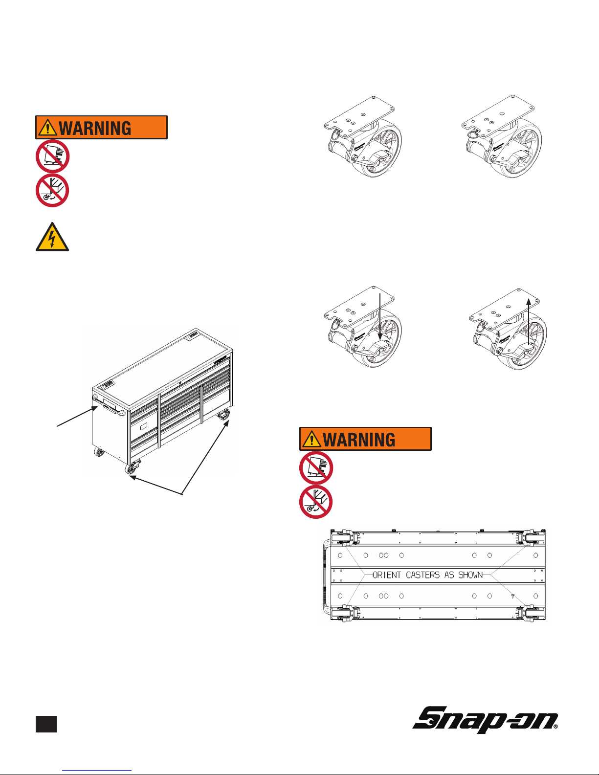
Do not pull. Push to move. If your tool storage unit comes with all
swivel casters, use the swivel-lock pin to lock the two swivel casters opposite the handle as shown before attempting to move. If
your tool storage unit comes with two swivel and two rigid caters,
install handle on the same side as the swivel casters.
MOVING & STORAGE INSTRUCTIONS
CONT.
Casters can be converted from swivel to rigid by pulling and rotating
the swivel lock pin.
Casters will swivel with
swivel lock pin locked in
the outward position as
shown.
Casters can be locked and unlocked by applying pressure to the
caster brake. The brake on the caster stops the caster wheel from
rolling when pressed down in the locked position. When lifted up,
the caster will be unlocked and the wheel will be able to roll.
Casters will not swivel
when swivel lock pin
is locked in the inward
position as shown.
Do not pull.
Push to move.
Rigid casters. If
swivel casters, lock
swivel casters opposite handle prior to
Swivel Casters
moving.
If your tool storage unit has swivel-locks, be sure lock the swivel
caster wheels parallel to the front of the roll cab prior to opening
any drawers. Do not open any drawer with swivel caster positioned inward.
When brake is compressed,
caster wheel will be in the
locked position and will be
unable to roll.
Units can tip or strike you.
• Apply brakes on casters when not moving unit
• Do not open any drawer with swivel caster positioned
inward
Tipping of storage unit or unit striking you can cause injury.
When brake is in the up
position caster wheel will
be in the unlocked position
and will be able to roll.
14
4
ZECKOROLL REV ‘A’ OCT 2018
Page 5

FCC Notice
This device complies with part 15 of the FCC rules. Operation is subject to the following two conditions: (1)
This device may not cause harmful interference; and (2) This device must accept any interference received,
including interference that may cause undesired operation.
Le présent appareil est conforme aux CNR d’Industrie Canada applicables aux appareils radio exempts de
licence. L’exploitation est autorisée aux deux conditions suivantes: (1) l’appareil ne doit pas produire de brouillage, et (2) l’utilisateur de l’appareil doit accepter tout brouillage radioélectrique subi, même si le brouillage est
susceptible d’en compromettre le fonctionnement.
Note: This equipment has been tested and found to comply with the limits for a Class B digital device, pursuant
to part 15 of the FCC Rules. These limits are designed to provide reasonable protection against harmful interference in a residential installation. This equipment generates, uses, and can radiate radio frequency energy and, if
not installed and used in accordance with the instructions, may cause harmful interference to radio communications. However, there is no guarantee that interference will not occur in a particular installation. If this equipment
does cause harmful interference to radio or television reception, which can be determined by turning the equipment off and on, the user is encouraged to try to correct the interference by one or more of the following measures:
• Reorient or relocate the receiving antenna
• Increase the separation between the equipment and receiver
• Connect the equipment into an output or circuit different from that to which the receiver is connected
• Consult the dealer or an experienced radio/TV technician for help
14
5
ZECKOROLL REV ‘A’ OCT 2018
Page 6

Table of Contents
Features.........................................................................................6
Specications.................................................................................6
Manual Locking / Unlocking...........................................................7
Setting Up ECKO Remote Lock.....................................................8
Remote Use...................................................................................8
Maintenance...................................................................................9
Remote Battery Replacement....................................................9
Replacing Remote Lock Module Fuse.......................................9
Remote Pairing........................................................................10
Resetting Remote Lock Receiver Module................................11
Speaker Volume Adjustment....................................................11
Troubleshooting............................................................................12
Service..........................................................................................13
Features
• Unlock or lock from a distance
• Manual key override
• Remote can be keyed to work several
electronic locks at once
• Spare remote included
• Thermal overload protection
• Maintenance free design
• Small ergonomic remote
• Audible signal of unlock or lock
• On/Off switch
Specications
Remote
Power Lithium CR2032 3 Volt
Battery
Life
Storage Temperatures from -20°F to
2-3 Years
140°F
Remote Lock Module
Power 120V AC to 24V DC Power
Converter
Storage Temperatures from -20°F to
140°F
The ECKO (Electronically Controlled Keyless Operation) remote locking system is designed to give the
user ease of locking and unlocking tool storage units
(TSU’s) without the hindrance of using a key(s). This
TSU is equipped with a receiver module that receives
a coded transmission from the remote transmitter. The
ECKO remote lock receiver module will either lock
or unlock the storage unit. The following service tips
should help in the proper care and maintenance of your
ECKO remote lock equipped TSU.
Manual Locking / Unlocking
ECKO remote lock units use a unique lock with only
one position that the key can be removed. Follow these
instructions to manually unlock your TSU for the rst
time:
Push the key into the lock cylinder and unlock by turning the key to the 9:00 position. Return the key back to
the 12:00 position and remove the key.
The ECKO remote lock unit can also be locked manually. Push the key into the lock cylinder and lock by
turning the key to the 3:00 position. Return the key back
to the 12:00 position and remove the key.
This manual override feature can be used if the batteries in the remote are non-functioning or the remote
is lost. Be sure to store mechanical lock keys in a safe
place outside of your TSU.
14
6
ZECKOROLL REV ‘A’ OCT 2018
Page 7

Setting Up ECKO Remote Lock
Each remote lock equipped TSU comes pre-programmed from the factory with the drawers
locked. Follow these steps to setup your ECKO
remote lock for the rst time:
Maintenance
Remote Battery Replacement
1. Locate keyway location on remote case.
1. Unlock the TSU using the procedure outlined
in the manual unlocking/locking section of this
manual.
2. Locate your AC/DC adapter and plug into
an electrical outlet that is properly installed and
grounded.
3. Plug the round DC end of the adapter into
the jack on the back of the TSU.
4. Use remote to lock or unlock the TSU as
explained in the remote section of the manual.
Remote Use
The remote is a three button design similar to an
automotive remote.
- Press lock key (1) 1-3 seconds to lock - 1 beep
will sound
- Press unlock key (2) 1-3 seconds to unlock - 2
beeps will sound
2. Using small at head screwdriver (or equivalent), separate two halves of remote case.
3. Remove battery (CR2032) out of its holding
bracket.
4. Slide new battery into holding bracket with positive (+) side up.
5. Reassemble remote case by pressing two
halves rmly together.
- Auxiliary (ACC) key is for future use
- If red LED does not turn on when pressing lock
or unlock, battery may be low
14
7
ZECKOROLL REV ‘A’ OCT 2018
Page 8

Remote Pairing
ECKO remotes come from the factory already
paired to the ECKO receiver module. This procedure will only be necessary if your remote has lost
pairing.
Follow these steps to pair the remote(s) with your
TSU:
1. Open top drawer of the TSU and locate the
ECKO receiver module.
2. Hold down the learn button on the module until
it starts to beep. The unit will beep for 1 second.
Release the learn button.
3. After beeping has stopped, pair remote by
pressing and holding the lock or unlock button
on the remote for approximately 3 seconds. The
receiver module will beep once to conrm pairing
was successful.
NOTE: If pairing multiple remotes, press and
holdthe lock button on each remote within the 10
second learn period. The module will end the pairing time period once the second remote is paired.
Only two remotes can be paired to one TSU.
Resetting Remote Lock Receiver Module
Follow these steps to reset the ECKO remote lock receiver module:
1. Open top drawer of the TSU and locate the receiver module.
2. Reset module by removing power cord from the
AC/DC adapter plug. Once removed, wait 5 seconds
before reinstalling power cord
Learn/Volume Button
AC/DC Adapter Plug
*Module view behind front dress plate
Note: If you are unable to reset module with the switch
due to the drawers being locked, unplug TSU from AC/
DC adapter and plug back in after 5 seconds.
Note: The remote(s) will not need to be re-paired to the
receiver module after resetting.
4. After 10 seconds, the receiver module will
beep twice to signify that the pairing time period is over.
Learn/Volume Button
*Module view behind front dress plate
Speaker Volume Adjustment
Follow these steps adjust the volume of your ECKO remote lock receiver module:
1. Open top drawer of the TSU and locate the receiver module.
2. Press the volume two times to change volume of
speaker.
3. Receiver will beep to conrm volume change.
• 1 Beep – Low Volume
• 2 Beeps – High Volume
• 3 Beeps – Volume Off
14
8
ZECKOROLL REV ‘A’ OCT 2018
Page 9

Troubleshooting
Symptom Possible Cause Solution
Remote battery low
Receiver module not receiv-
ing power
Remote lock does not respond,
remote lights up
Remote not paired with
receiver module
Remote out of range - Move closer to TSU
Reset needed
Self-test start up provides tone
other than 3 rising beeps
Remote does not light up Remote battery low
Response poor or intermittent
Drawer(s) still
unlocked after
locking unit
Receiver module speaker sounds
but unit does not lock/unlock
Receiver failed self-test
Remote battery low
Remote out of range - Move closer to TSU
Drawer(s) not fully closed
before locking
Actuator jammed or not mov-
ing freely
- Remove and reinstall
remote battery
- Replace remote battery
-
Plug AC/DC adapter into outlet and DC jack on rear
of roll cab
- Check blue power LED on AC/DC adapter
-
Check connection between DC
unit (TSU) and receiver module
- See Remote pairing section
of manual
- Unplug and re-plug remote lock cord on back of
ECKO receiver
- Unplug and re-plug remote lock cord on back of
TSU
Check sensor board and sensor board cable to
ensure correct assembly. Sensor board should
be connected to main board If damaged, replace
module
- Remove and reinstall remote battery
- Replace remote battery
- Remove and reinstall
remote battery
- Replace remote battery
- Drawer(s) not fully closed
before locking
- Push in drawer(s)
-
Manually unlock and lock TSU
actuator
- Unplug and re-plug remote lock cord on back of
ECKO receiver
- Unplug and re-plug remote lock cord on back of
TSU
cord in tool storage
to free lock rod and
Sensor board
14
9
ZECKOROLL REV ‘A’ OCT 2018
Main board
Sensor board cable
Page 10

Service – Removing Remote Lock
Module
Follow these steps to remove the ECKO remote
lock receiver module:
1. Remove top two drawers from roll cab.
2. Remove DC jack from remote lock mod-
ule.
Rear of front
dress plate view
3. Disengage snap-t and remove lock cover.
4. Disengage lock rod from cam mechanism.
Lock rod is spring loaded. Push toward back
of case and twist clock wise (with respect to
front) to disengage.
6. Remove nut and lock washer on back of lock.
7. Remove Lock.
8. Rotate remote lock module on mounting bracket.
Pull to right and remove.
5. Remove cam assembly screw. Swing cam
assembly down and out of the way.
14
10
ZECKOROLL REV ‘A’ OCT 2018
9. Reinstall in reverse order. When installing cam,
make sure that at on inner cam aligns with at on
lock.
Page 11

Service – Roll Cab Wiring
Service – Roll Cab Part Numbers
Follow these steps to replace the ECKO receiver
module wiring harness:
1. Remove top two drawers from roll cab.
2. Remove DC jack from remote lock module.
Rear of front
dress plate view
3. Remove wiring harness – disconnect from
plastic wire hangers and remove from rear of
unit.
8-72737BR
Receiver
Module with
Lock Cover
ECKOFOB
Remote
8-72737B-9A
Wiring
Harness
8-72737A-AC
AC/DC
Adapter
8-72737A-5
Lock Cover
4. Replace wire – feed from rear of unit and rein-
stall to plastic wire hangers. Bundle and secure
extra wire in false side gap(s). Make sure that
wire is not in the way of drawers.
5. Reinstall top two drawers
8-72737A-4
Lock Screw
8-72737A-60
Actuator
Assembly
RK1ULCA
Lock Cylinder
RK500KP –
RK699KP
Lock Plug
and 1 Key
RK1LA Lock Assy - 1 Lock, 2 Keys
RK2LA Lock Assy - 2 Locks, 2 Keys
RK3LA Lock Assy - 3 Locks, 3 Keys
RK4LA Lock Assy - 4 Locks, 4 Keys
RK5LA Lock Assy - 5 Locks, 5 Keys
RK6LA Lock Assy - 6 Locks, 6 Keys
RK7LA Lock Assy - 7 Locks, 7 Keys
14
11
ZECKOROLL REV ‘A’ OCT 2018
 Loading...