

查询EMC1002供应商查询EMC1002供应商
EMC1002
1°C Dual SMBus
Sensor with Resistance
Error Correction
PRODUCT FEATURES
General Description
The EMC1002 is an SMBus temperature sensor that
monitors up to two temperature zones and can generate
two system interrupts. With ±1°C measurement
accuracy, the EMC1002 provides a low-cost solution for
critical temperature monitoring applications. Extended
features include automatic resistance error correction
and programmable ideality factor configuration
eliminating both major sources of temperature
measurement error.
temperature-to-digital converter provides superb
linearity, excellent noise immunity and repeatable
temperature readings.
The EMC1002 generates two separate interrupts with
programmable thermal trip points. The THERM
operates as a thermostat with programmable threshold
and hysteresis. The ALERT output can be configured
as a maskable SMBus alert with programmable
window comparator limits, or a second THERM
The EMC1002 is pin compatible with the ADT7461,
ADM1032, LM99, and the MAX6649.
1.Patents pending.
1
The 11-bit sigma delta
output
output.
Data Brief
Features
■ Resistance Error Correction
■ Ideality Factor Configuration
■ Select 1 of 4 SMBus addresses with external resistor
■ Remote Thermal Zones
— ±1°C Accuracy (40°C to 80°C)
— 0.125°C resolution
■ Internal Thermal Zone
— ±3°C Accuracy (0°C to 85°C)
■ Maskable Interrupt using ALERT
■ One-shot Command during standby
■ Programmable temperature conversion rate
■ Extended temperature (-64°C to 191°C) available
■ Over-limit filtering with consecutive counter
■ Small 8-lead SOIC or MSOP package; lead-free also
available
Applications
■ Desktop and Notebook Computers
■ Smart batteries
■ Industrial/Automotive
■ Other Electronic Systems
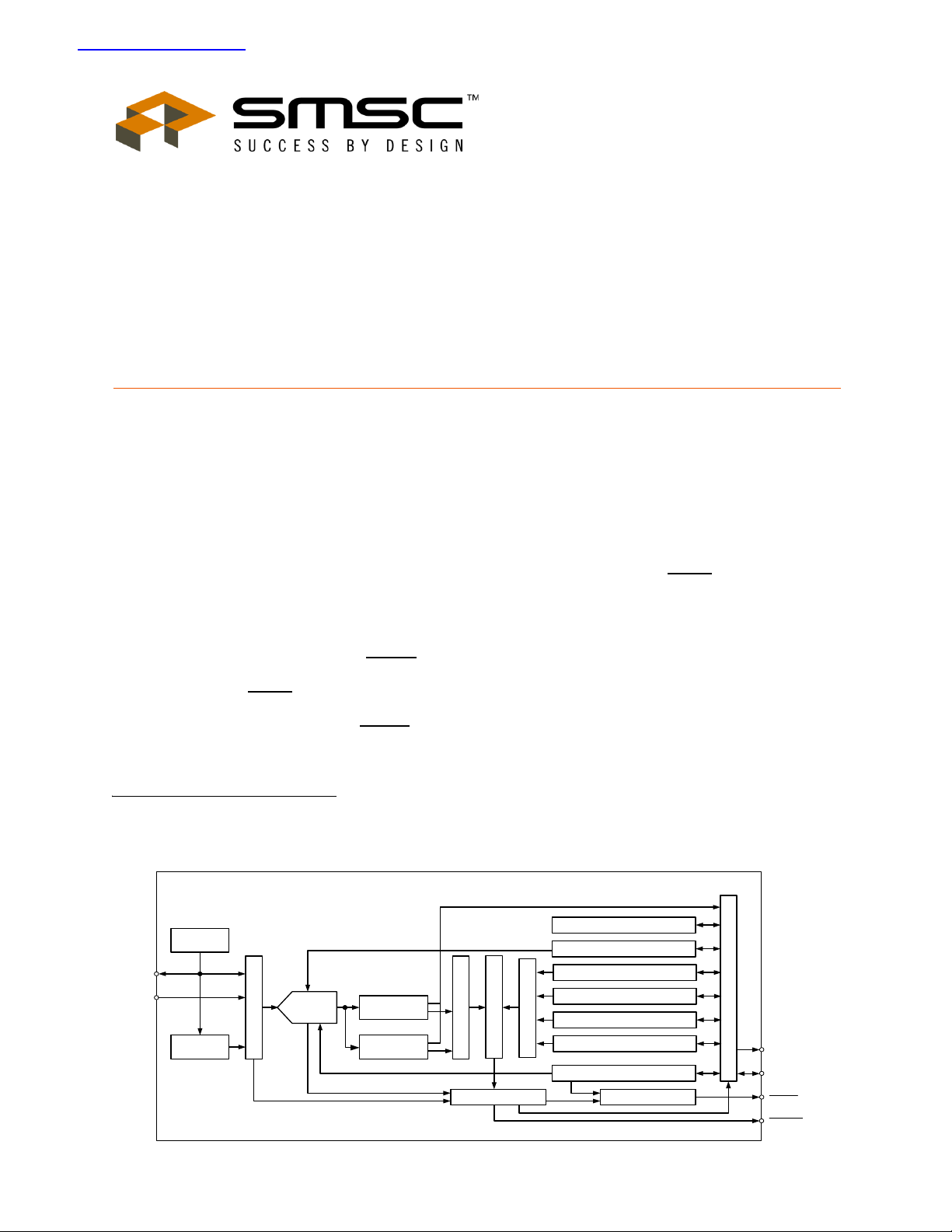
Simplified Block Diagram
EMC1002
Switching
Current
DP
Analog Mux
11-bit
delta-sigma
ADC
Remote Temp
Register
Internal Te mp
Register
Digital Mux
Limit Comparator
DN
Internal
Temp Diode
SMSC EMC1002 PRODUCT PREVIEW Revision 1.2 (04-15-05)
Address Pointer Register
Conversion Rate Register
High Limit Registers
Low Limit Registers
THERM Limit Register
Digital Mux
THERM Hysteresis Register
Configuration Register
SMBus Interface
SMCLK
SMDATA
Interrupt M askingStatus Register
ALERT
THERM
1°C Dual SMBus Sensor with Resistance Error Correction
r
A
ORDER NUMBER(S):
EMC1002-1-ACM-TR FOR 8 PIN, SOIC PACKAGE (Fixed Address, Tape and Reel)
EMC1002-2-ACM-TR FOR 8 PIN, SOIC PACKAGE (Variable Address, Tape and Reel)
EMC1002-1-ACZT-TR FOR 8 PIN, SOIC GREEN, LEAD-FREE PACKAGE (Fixed Address, Tape and Reel)
EMC1002-2-ACZT-TR FOR 8 PIN, SOIC GREEN, LEAD-FREE PACKAGE (Variable Address, Tape and Reel)
EMC1002-1-ACZB-TR FOR 8 PIN, MSOP PACKAGE (Fixed Address, Tape and Reel)
EMC1002-2-ACZB-TR FOR 8 PIN, MSOP PACKAGE (Variable Address, Tape and Reel)
EMC1002-1-ACZL-TR FOR 8 PIN, MSOP GREEN, LEAD-FREE PACKAGE (Fixed Address, Tape and Reel)
EMC1002-2-ACZL-TR FOR 8 PIN, MSOP GREEN, LEAD-FREE PACKAGE (Variable Address, Tape and Reel)
Reel size is 4,000 pieces.
Evaluation Board available upon request. (EVB-EMC1002)
Hauppauge, NY 11788
(631) 435-6000
FAX (631) 273-3123
80 Arkay Drive
Copyright © SMSC 2005. All rights reserved.
Circuit diagrams and other information relating to SMSC products are included as a means of illustrating typical applications. Consequently, complete
information sufficient for construction purposes is not necessarily given. Although the information has been checked and is believed to be accurate, no
responsibility is assumed for inaccuracies. SMSC reserves the right to make changes to specifications and product descriptions at any time without
notice. Contact your local SMSC sales office to obtain the latest specifications before placing your product order. The provision of this information does
not convey to the purchaser of the described semiconductor devices any licenses under any patent rights or other intellectual property rights of SMSC
or others. All sales are expressly conditional on your agreement to the terms and conditions of the most recently dated version of SMSC's standard
Terms of Sale Agreement dated before the date of your order (the "Terms of Sale Agreement"). The product may contain design defects or errors
known as anomalies which may cause the product's functions to deviate from published specifications. Anomaly sheets are available upon request.
SMSC products are not designed, intended, authorized or warranted for use in any life support or other application where product failure could cause
or contribute to personal injury or severe property damage. Any and all such uses without prior written approval of an Officer of SMSC and furthe
testing and/or modification will be fully at the risk of the customer. Copies of this document or other SMSC literature, as well as the Terms of Sale
greement, may be obtained by visiting SMSC’s website at http://www.smsc.com. SMSC is a registered trademark of Standard Microsystems
Corporation (“SMSC”). Product names and company names are the trademarks of their respective holders.
SMSC DISCLAIMS AND EXCLUDES ANY AND ALL WARRANTIES, INCLUDING WITHOUT LIMITATION ANY AND ALL IMPLIED WARRANTIES
OF MERCHANTABILITY, FITNESS FOR A PARTICULAR PURPOSE, TITLE, AND AGAINST INFRINGEMENT AND THE LIKE, AND ANY AND
ALL WARRANTIES ARISING FROM ANY COURSE OF DEALING OR USAGE OF TRADE.
IN NO EVENT SHALL SMSC BE LIABLE FOR ANY DIRECT, INCIDENTAL, INDIRECT, SPECIAL, PUNITIVE, OR CONSEQUENTIAL DAMAGES;
OR FOR LOST DATA, PROFITS, SAVINGS OR REVENUES OF ANY KIND; REGARDLESS OF THE FORM OF ACTION, WHETHER BASED ON
CONTRACT; TORT; NEGLIGENCE OF SMSC OR OTHERS; STRICT LIABILITY; BREACH OF WARRANTY; OR OTHERWISE; WHETHER OR
NOT ANY REMEDY OF BUYER IS HELD TO HAVE FAILED OF ITS ESSENTIAL PURPOSE, AND WHETHER OR NOT SMSC HAS BEEN
ADVISED OF THE POSSIBILITY OF SUCH DAMAGES.
Revision 1.2 (04-15-05) 2 SMSC EMC1002
PRODUCT PREVIEW

1°C Dual SMBus Sensor with Resistance Error Correction
Package Outlines
Figure 1 8-Pin MSOP and 8-Pin MSOP (Lead-Free) Package Outline - 3x3mm Body 0.65mm Pitch
Table 1 8-Pin MSOP and 8-Pin MSOP (Lead-Free) Package Parameters
MIN NOMINAL MAX REMARKS
A 0.80 ~ 1.10 Overall Package Height
A1 0.05 ~ 0.15 Standoff
A2 0.75 0.85 0.95 Body Thickness
D 2.80 3.00 3.20 X Body Size
E 4.65 4.90 5.15 Y Span
E1 2.80 ~ 3.20 Y body Size
H 0.08 ~ 0.23 Lead Foot Thickness
L 0.40 ~ 0.80 Lead Foot Length
L1 0.95 REF Lead Length
e 0.65 BSC Lead Pitch
o
θ
W 0.22 ~ 0.38 Lead Width
ccc ~ ~ 0.10 Coplanarity
0
Notes:
1. Controlling Unit: millimeters.
2. Tolerance on the true position of the leads is ± 0.065 mm maximum.
3. Package body dimensions D and E1 do not include mold protrusion or flash. Dimensions D and
E1 to be determined at datum plane H. Maximum mold protrusion or flash is 0.15mm (0.006 inches)
per end, and 0.15mm (0.006 inches) per side.
4. Dimension for foot length L measured at the gauge plane 0.25 mm above the seating plane.
5. Details of pin 1 identifier are optional but must be located within the zone indicated.
~8
o
Lead Foot Angle
SMSC EMC1002 3 Revision 1.2 (04-15-05)
PRODUCT PREVIEW

PRODUCT PREVIEW
REV
SHEET
SMSC EMC1002 4 Revision 1.2 (04-15-05)
REVISION HISTORY
DESCRIPTIONREVISION RELEASED BYDATE
A INITIAL RELEASE 7/07/04 S.K.ILIEV
GATE B URRS. MAXI MUM MOL D FLASH, P ROTRUSIONS OR GA TE BURRS IS 0.15 mm PER
END. DI MENSIO N "E1" DOE S NOT INCL UDE INTE RLE AD FL AS H OR PRO TRUSION.
MAXIM UM INT ERLEAD FLASH OR PROTRUSION IS 0. 25 mm PER SIDE. "D1" & "E1"
DIMENSIONS ARE DETERM INED AT DATUM PLANE "H".
4. DI MENSIONS "b" & "c" APPLY T O THE FLAT SECTI ON OF THE LEAD BETWEEN 0.10 TO
2. TRUE POSITION SPREAD TOLERANCE IS ± 0.125mm AT MAXIMUM MATERIAL CONDITION.
3. PACKAGE BO DY DIMENSION "D" DOES NOT INCLUDE MOLD FLA SH, PROTRUSIONS OR
NOTES:
1. ALL DIMENS IONS ARE IN MILLIM ETER.
0.25 m m FROM THE LEAD TIP.
THIRD ANGLE PROJECTION
MUST BE LOCATED WITHI N THE INDEX AREA INDICATED.
5. THE CHAMFER FE ATURE IS OPTIO NAL. IF IT I S NOT PRESENT, THEN A PIN 1 IDENTIFIER
UNLESS OTHERWISE SPECIFIED
PACKAGE OUTLINE
80 ARKAY DRIVE
HAUPPAUGE, NY 11788
USA
TITLE
DATE
NAME
DRAWN
±1°
ANGULAR
±0.025
±0.05
±0.1
AND TOLERANCES ARE:
DIMENSIONS ARE IN MILLIMETERS
DIM AND TOL PER ASME Y14.5M - 1994
X.X
X.XX
X.XXX
DECIMAL
MATERIAL
JEDEC: MS-012 / AA 1 OF 1
STD COMPLIANCE
MO-8-SOIC-4.9x3.9
8 PIN SOIC, 3.9mm BODY WIDTH, 1.27mm PITCH
SCALE
DWG NUMBER
7/07/04 1:1
7/07/04
7/07/04 A
S.K.ILIEV
S.K.ILIEV
S.K.ILIEV
APPROVED
CHECKED
-
-
DO NOT SCALE DRAWING
PRIN T WIT H "SC ALE TO FIT"
FINISH
c
4
SEE DETAIL "A"
END VIEW
3-D VIEW
A
E
2 4
e
3
D
8
8X b
12
TOP VIEW
E1
3
A2
A1
C
SIDE VIEW
ccc
SEATING PLANE
C
0.25
0
H
GAUGE PLANE
L
L1
SCALE: 3/1
DETAIL "A"
Figure 2 8-Pin SOIC and 8-Pin SOIC (Lead-Free) Package Outline and Parameters - 3.9mm Body 1.27 mm Pitch
(D/2 X E1/2)
INDE X AREA
5
 Loading...