

Page 1

Service
System
250
Manual
Fluid
Warmer
:
Unpacking
Filling
Electricat
Alarm
Performance
Maintenance
Troubleshooting
Limited
Service
Specifications...
Electrical
Parts
Mechanical
and
with
Distilled
Safety
Power
Leakage
Testing
Testnd
Inoperable
Flow
Restriction,
Warranty
Schematics
List,
Maintenance
Parts
Set-Up
Reguirement.
Current
.
List
..
Water
ii
System
and
.
Test.
250
|.V.
Disposable
User
Sets
Replaceable
Parts
6
…
Revised
REV
A
May
1993
215)
Page 2

Purpose
The
Level 1 System
patients.
The
Minimum
are
Level 1 1.V.
board
infusion
warming
Disposable
standard
delivery
delivered
safety
of
for
250
sets
Disposable
temperature
near
37°C.
Sets,
and
and
monitoring
normothermic
and
|.C.U.
is
designed
specifically
Set
allows
at
Blood
and
will
be
delivered
systems
fluids.
Emergency
for
designed
infusion
these
packed
make
Typical
Room
safe
and
for
of
6°C
flow rates
RBCs
near 37°C.
the
Level 1 System
uses
of
use.
rapid
various
blood
is
35°C.
from
ail
High
the
system
in-line
warming
infusion
up
to
At
the
auto
warming
of
rates
are
100
ml/min.
somewhat
transfusion
and
flow
250
the ideal
include
all
|.V.
fluids
available.
or
6°C
crystalloid
lower
flow rates
systems
capacity,
choice
routine
surgery
as
may
simple
for
they
are
generally
be
infused
all
procedures
and
_
administered
up
to
150
used,
through
operation,
blood
to
mMmin.
fluids
the
and
on-
requiring
and
fluid
Messages
improper
results.
Messages
cause
improper
Messages
cause
improper
Concept
The
Level 1 System
makes
used
The
rapidly
rapid
System
Taking
very
available
in
the
System
circulated
water
250.
advantage
cold
blood.
that
are
headed
that
are
headed
results
that
are
headed
results,
to
all
Open
Heart
250
employs a Disposable
counter-flow
circulation,
of
The
Filter
and
250
other
the
by
by
damage
by
damage
is
the
areas
Suite
for
and
counter-flow
high
Holder
“NOTE:"
indicate
“CAUTION:"
to
the
“WARNING:"
to
the
equipment,
first
significant
of
the
on-pump
through
warming
of
an
capacity,
the
System
information
indicate
equipment.
indicate
advance
hospital
warming
Heat
Exchanger.
anodized
warming
the
250
or
information
information
injury
to
personnel,
in
routine
the
same
for
over
25
As
aluminum
all
contribute
Disposable
is
warmed
procedures
or
procedures
or
procedures
or
blood
fluid
warming
years.
with
extracorporeal
tube.
The
to
the
Sets
allow
to
help
maintain
that
if
not
that i not
`
that
serious
and
use
excellent
patient
fluid
technology
of a thermal
increased
peak
followed
followed
if
not
followed
harm.
warming
Perfusionists
warming,
conductor
high
warming
fluid
efficiency
correctly
correctly can
correctly
in
over
warmed
capacity
flow
rates,
at
low
can
cause
can
20
years.
have
water
It
safety
is
(aluminum),
of
the
even
with
flow
rates.
The
Hardware
and
easy
to
use.
the
system
safely
Safety
FILTER
The
released
delivered
WITH
Level 1 Disposable
from
to
the
and
Disposables
By
following
set-up
GAS
VENT
fluids
as
patient
and
Sets
they
along
of
the
Level 1 System
the
1-2-3
instructions
operating
employ a unique
are
with
within
warmed.
the
warmed
seconds.
In
many
fluids.
Gas
found
Vent
other
250
on
which
warming
are
integrated
the
unit,
vents
into
properly
micro-bubbles
systems,
the
design
trained
these
to
be
highly
users
can
confidently
of
gas
which
micro-bubbles
effective
are
always
are
actually
have
Page 3

The
ability
Gas
Vent
with
luer-locks
Fitter
vent
replacement
For
D-50
For
D-100
with
of
in
gas
Set
Set
the
the
and
vent
order
order
Gas
Vent
I.V.
Sets
is
easily
should
fitters
are
replacement
replacement
to
quickly
contains a 170-micron
changed
be
changed
available
fitter
without
as
F-10
filter
F-10
vent
air
every
follows:
patient
three
also
screen
permits
hours
rapid
filter
to
trap
disconnection
to
maintain
priming
of
the
macro-aggregates.
or
repriming
efficient
system
Disposable
This
of
the
entire
performance.
Set.
The
filter
is
disposable
Fitter
Fitter
with
connected
set.
he
with
gas
TEMPERATURE
The
System
temperature
this
circuit, a second
temperature
Fluid
present
temperatures.
ELECTRICAL
A
special
through
low
the
power
CONTROL
250
employs a safe
control
reaches
in
the
circuit
“watchdog”
about
heat
SAFETY
leakage
cord
limits
41°C.
exchanger
immersion
providing
circulating
the
circulating
circuit
will
while
heater
an
is
extra
Unpacking
The
Level 1 System
Contents
water
water
visually
the
unit
used
measure
heating
to a 40°C
and
audibly
is
operating
in
the
Level 1 System
of
patient
and
Set-Up
250
system,
maximum.
alarm
is
and
is
packaged
inherently
and
never
exposed
250.
operator
and
tn
the
stop
This
safety.
partially
Quantity
free
of
unlikely
the
circulating
to
any
heater
assembied.
"hot
spots".
event
of a malfunction
water
damaging
is
electrically
The
primary
pump
or
dangerous
grounded
if
of
the
Figure
UNIT
PACKAGING
Power
Rolling
ACCESSORY
Service
Operators
Casters
ГУ
IV.
Fill
Set
Level 1 Video
Hitch
1
Вад
Pole
Plug
Up
Pin
Unit
Base
Manual
Manual
Напдег
Knob
Card
1
1
PACK
a
da
一
一 一
一
一
一
Page 4

WARNING
This
unit
prior
to
1,
With
wheels.
2.
Slide
base
as
3.
insert
must
placing
the
Rolling
the
Power
shown
the
PIN
be
assembled
the
device
base
Unit
in
Figure
through
into
on
Pole
1.
the
and
service.
its
side,
down
holes
tested
push
over
in
the
by
Level 1 technical
the
four
the
vertical
bottom
of
casters
square
the
pole
FULLY
base
and
personnel
into
their
tube
with
vertical
or
sockets.
Power
base
an
authorized
Unit
tube,
Place
facing
locking
distributor
the
base
the
longer
them
together.
of
Level
upright
side
of
on
1
its
the
Filling
Set-Up
CAUTION
For
WATER
water
operating
DO
creates
A.
B.
port
in
Figure
way
port
proper
in
the
NOT
an
Unscrew
Fil
with
exits
3.
to
be
and
fill
with
system
should
unit
efficiency.
FILL
air
and
1.3
at
the
This
sure
the
Distilled
operation
be
used
will
build
the
unit
lock
preventing
remove
liters
of
bottom
vent
port
the
reservoir
reservoir
Water
and
in
the
up
mineral
with a DISPOSABLE
proper
the
Fillport
Distilled
of
the
also
is
until
water
component
water
Plug.
Water.
Power
serves
full
is
begins
life,
reservoir.
scale
and
SET
filling.
Note: A water
Module
as
to
at
an
overflow
place a cup
to
exit
only
DISTILLED
The
use
seriously
IN
PLACE
reservoir
the
location
tube.
under
the
port.
of
reduce
as
this
vent
shown
An
easy
this
vent
tap
its
Fillport
Plug
Figure
2
C.
Replace
CAUTION
The
Distilled
manual.
sure
there
The
are
the
Fillport
Water
System
no
in
250
large
Plug
the
reservoir
draws a maximum
power
consumers
should
on
be
of
7.5
that
changed
Amps.
circuit.
every
It
should
30
days.
be
plugged
See
the
Maintenance
into a 10
to
20
section
Amp
of
circuit,
being
this
Page 5

Electrical
Safety
Power
Requirement
Most
of
the
current
600
Watt
immersion
turned
temperatures
full
proportional
proportionally
water
Leakage
on
and
ON
condition.
nears
controller
the
Current
drawn
the
digital
below
Beyond
shorter
40°C
heater.
30°C,
cycles
target
Test
NOTE
This
device
device
the
Parts
WARNING
DO
NOT
WITHOUT A DISPOSABLE
and
is
equipped
perform
List
section
DEFEAT
leakage
of
THE
΄
by
the
System
When
display
the
shows
600
approximately
the
heater
ON
times
temperature.
with
disposable
current
this
manual.
DISPOSABLE
HEAT
250
the
device
rapidly
Watt
heater
30°C,
ON/OFF
as
the
circulating
sensing
testing.
EXCHANGER
Non-Sterile
SENSING
is
for
its
is
first
rising
is in
a
the
with
interlocks. A Level 1 Heat
Test
Sets
are
INTERLOCKS
IN
PLACE.
Exchanger
available
OR TRY
Figure
from
Level 1 for
TO
Air
intake
3
is
required
this
OPERATIVE
Vent
Port
Slots
to
operate
purpose.
THE
the
See
UNIT
Power
in
be
warms
Although
less
Units
repair.
On
order
performed
up
than
exceeding
Alarm
NOTE
Alarm
avatlable
testing
Leakage
to
be
quickly,
the
specifications
50
microamps.
sure
on
100
Current
the
immersion
units
test
readings
microamps
which
Testing
requires a Level 1 Heat
from
Level 1 for
this
Tests
have
should
claim
purpose.
should
heater
less
electrical
circuit
been
be
than
Exchanger
See
be
allowed
taken
100
・
leakage
the
performed
is
in a full
to
stand
within 1 minute
microamps
should
to
be
Parts
List
with
the
ON
condition,
until
electrical
be
removed
in
place
in
this
immersion
Power
close
to
of
startup.
leakage,
from
on
the
manual.
heater
On
room
temperature.
units
service
System
circuit
Leakage
leaving
and
250.
Non-sterile
in
the
full
Current
As
the
the
factory
returned
ON
condition.
Tests
should
System
are
usually
to
Level 1 for
Test
Sets
250
are
Page 6

Add
Water
The
System
water
level
condition
Alarm
250
is
too
the
circulating
is
equipped
low, a RED
pump
with a float
L.E.D.
should
on
not
switch
the
Display
be
running.
which
senses
Panel
the
water
illuminates
level
in
the
and a sonic
on-board
alarm
reservoir,
sounds.
In
When
the
the
alarm
With a Test
tube
on
the
Replace
Check
Two
and
running,
1.
2.
Over
any
Disposables
interlocks
the
Power
each
Top
Heat
Heat
Exchanger
Temperature
With a Test
the
water
Fil/Drain
DISTILLED
this
manual.)
illuminate
above,
normal
and
turn
operation.
Heat
Exchanger
back
of
the
Power
water
drained
Alarm
sense a property
Switch
interlock
Exchanger
is
may
Socket - Pull
Guide - Bend
Alarm
Heat
Exchanger
tube
on
WATER
the
Turn
the
Power
which
the
Sonic
Switch
Power
Alarm
in
place,
Unit
with
DISTILLED
installed
ON,
the
RED
be
independently
tube
in
place and
the
back
has
been
Switch
should
OFF
and
the
ADD
and
tilting
Heat
indicator
Release
portion
the
of
the
heated
ON.
sound.
allow
WATER
it
down
WATER.
Exchanger.
tested:
knob
of
Heat
Power
Power
to
45°C
The
Over
The
the
unit
ALARM
to
See
will
illuminate
and
slide
Exchanger
Switch
Unit
and
to
48°C.
temperature
water
circulating
to
cool
may
allow
some
the
Filling
If a properly
and a pulsed
up.
out
OFF,
drain
tilting
it
(See
FILLING
pump
to
room
be
tested
of
the
water
with
Distilled
installed
of
Guide
down
RED
groove.
the
water
to a container.
WITH
L.E.D.
should
temperature.
by
releasing
to
drain
Water
Heat
Exchanger
alarm
will
out
of
the
DISTILLED
on
the
not
be
Restart
the
out
section
sound.
reservoir
Fill
WATER
Display
running.
the
water
Fil/Drain
into a container.
of
this
manual.
is
not
in
place
With
the
unit
by
releasing
with
1.3
liters
of
section
Panel
Confirming
unit
and
of
should
the
confirm
NOTE
The
sonic
alarm
Performance
NOTE
Performance
Disposable
THREE
1.
COLD
Store
in
piace,
Rapidly
minutes
simpie
the
rising
on
Test
START
System
note
an
and
all
RED
Testing
testing
the
numbers
efficiently
requires a Level 1 0-50
Sets
are
tests
allow
TEST
250
unit
time
and
will
operating
L.E.D.s
available
periodic
in a room
turn
checking
the
appear
unit.
may
from
Level 1 for
where
Power
on
be
the
tested
Disposable
of
the
the
room
Switch
Water
by
pressing
Set
this
purpose.
overall
operating
temperature
ON.
The
Temperature
the
to
See
Green
alarm
test
be
in
place
the
Parts
efficiency
is
approximately
System
display.
37°C
button
of
on
List
the
21°C
on
the
System
section
System
Operational
will
appear
the
back
250.
in
this
250.
(70°F).
With a D-50
indicator
in
approximately
of
the
cabinet.
Non-sterile
manual.
will
illuminate.
Set
3
Page 7

2.
SYSTEM
RECOVERY
TEST
Chill a 1
allow
the
place
the
Pole
so
at
250
mUmin.
Note
the
display.
not
read
3.
STEADY
Thermal
For
use
NOTE
Use
of
this
accurate
liter
bag
of
unit
to
reach
Male
Luer
the
fluid
bag
(This
time
and
OPEN
The
fluid
bag
below
37°C.
STATE
Calibration
with:
within
Level 1 Fluid
unit
requires a digital
0.1°C.
Normal
in a container
may
RUN
Well
at
least
outlet
be
the
should
TEST:
(TCW)
Saline
39.5°C.
is
4"
confirmed
clamp
empty
Warmers
thermometer
to
10°C
to
Remove
on
the
floor.
above
the
level
with a graduated
below
the
in
about 4 minutes,
'.
Model
15°C.
the
Close
of
bag,
P/N
H-500
H-500
H-250
H-250
NIST
With a D-50
cap from
the
Bag
the
Heat
Exchanger
beaker
allowing
80-03-002
traceable
and
INT
INT
the
the
and
Test
the
Spike
and
fluid
digital
Set
in
place,
Male
Luer
clamps,
inlet.
stopwatch.)
to
flow
freely.
display
at
and
With
in
the
spike
an
turn
the
Power
end
of
the
the
fluid
all
clamps
Watch
the
efficiently
Switch
Patient
bag.
open,
fluid
Water
Temperature
operating
Set
ON
Line
the
will
unit
and
and
LV.
flow
will
Required
Short
a.
Install
(sockets 1 &
“For
b.
Turn
thermometer
Compare
Unit
correctly
Examples
Thermometer
Level 1 Unit
probe
checklist
TCW
H:500 & H-500
the
temperatures.
display
calibrated
size:
to
verify
in
machine
2).
machine
probe
will
be
39.750
WITHIN
0.099"
0.50" - 1.50"
displayed
INT,
on
and
fully
into
within
unit.
THIS
in
normal
also
install a test
allow
well
0.3°C
of
RANGE
OD
maximum
long
circulating
heat
to
warm
and
allow
the
thermometer
39.4°C - 40.0°C = OK
water
exchanger
filter
at
up
for
15
display
temperature:
position
position
to
display
3.
minutes.
stabilize.
on
Insert
a
7 し
pe
|
一
3
一
一
圖
一
1
Page 8

Thermometer
Levelt
NOTE
IF
SERVICE.
THE
Unit
SYSTEM
Maintenance
40.0°C
WITHIN
250
THIS
DOES
RANGE
NOT
39.7°C - 40.3°C = OK
MEET
1,
2,
or
3,
IT
SHOULD
BE
RETURNED
TO
THE
FACTORY
FOR
CLEAN
Clean
and a soft
discolor
CHANGE
Release
container.
water.
GREASE
Place a small
Rings
sockets
CHANGE
Note:
the
socket
Ring
Caps
EXTERIOR
the
entire
some
DISTILLED
the
See
O-RING
in
the
to
O-RING
An
O-Ring
Parts
List
and
sockets.
and
button
cloth
Replace
FILLING
grease
remove
System
after
of
the
water
amount
bottom
Kit
jn
this
Coat
head
--
EVERY
every
plastics
WATER
Fil/Drain
the
tube
WITH
SEALS
of
and
top
them.
SEALS
containing 2 O-Rings, 1 1/8"
manual.
the
rectanguiar
the
new
screws.
USE
250
with a spray
use.
Cold
on
the
--
tube
by
pushing
DISTILLED
--
EVERY
silicone
heat
--
EVERY
Using a 1/8"
O-Rings
sterilizing
device.
EVERY
behind
firmiy
WATER
30
DAYS
grease
exchanger
on a cotton
12
MONTHS
Socket
with
of
Do
30
the
hex
Caps.
silicone
warm
solutions
not
DAYS
Power
up
into
section
sockets
hex
wrench,
After
grease
soapy
use
Unit
the
swab
of
wrench
unscrew
removing
water
may
be
cleaning
and
tilt
fitting
of
this
or
the
the
Pole
and
and
press
solution
used,
agents
it
down
until
it
bottoms.
manual.
end
of a smali
Assembly.
silicone
the
four
and
discarding
them
or a commercial
but
strong
containing abrasives.
to
allow
It
grease
stainless
into
the
Refill
finger
is
not
is
button
the
their
chemical
non-abrasive
concentrations
water
to
with
1.3
and
apply
necessary
available
head
old
O-Rings,
sockets.
drain
into
liters
of
all
around
to
disassemble
from
Level
screws
clean
Replace
cleaner
may
a
distilled
the
1.
See
of
each
the
O-
the
Socket
O-
the
GENERAL
INSPECTION
--
EVERY
USE
Visually
service
Disposable
This
bottom
Pole
check
which
unit
is
of
mount ( figure
the
shows
Set
cooled
the
cabinet
condition
physical
does
not
by
4)
of
damage
install
convection.
(refer
to
are
not
blocked.
Air
Vent
Figure
4
the
device.
easily.
Be
Figure
or
one
sure
3)
and
Remove
in
which
the
air
air
any
the
intake
vent
below
unit
Test
slots
from
on
the
the
Ι.Ν.
Page 9

Troubleshooting
Inoperable
System
PROBLEM
NO
POWER
NO
GREEN
OPERATIONAL
and
CHECK
ALARM
ADD
WHEN
DISPOSABLES
WATER
UNIT.IS
250
SYSTEM
ALARM
MOVED
LIGHT
CHECK
Unit
is
PLUGGED
Power
Minimum
Note:
from
Switch
will
Heat
properly
Pole
property
Switch
If
power
the
is
GLOW.
Exchanger
installed?
interlocks
engaged
Exchanger?
Add
about
water
to
the
Fill
Port.
ON?
10
AMP
is
wall
and
turned
(2)
150
mt
reservoir
IN?
circuit?
reaching
the
Power
ON,
the
switch
by
the
Heat
distilled
through
the
unit
the
ADD
WHEN
ON
OVER
ALARM
WATER
UNIT
ALARM
IS
TEMPERATURE
TURNED
Fill
with
distilled
alarm
stops.
Manual
filling
Turn
and
service.
or
for
complete
instructions.
off
the
remove
It
must
replaced
by
Technologies,
Note:
Room
above
unusual
off
40°C,
before
situation,
returning
water
until
Refer
to
Service
draining
Power
the
Switch
Unit
be
repaired
Level
from
1
Inc.
temperature
may
cause
turn
the
it
to
service.
above
the
Power
and
40°C
H-250
(104°F)
to
shut
Switch
down
OFF
or
filling
and
and
allow
with
alarm.
the
distilled
In
unit
this
to
water
cool
Page 10

LONG
HOT
POWER
CABINET
WARM
UP
MODULE
Unit
stored
environment?
Blocked
Assembly?
perforated
the
I.V.
air
round
Pole
in
an
vent
on
(The
air
black
mount.)
unusually
Pole
vent
is
disc
cold
the
below
HARD
HEAT
WATER
TO
EXCHANGER
LEAKS
EXCHANGER
INSTALL
AT
SOCKETS
HEAT
Grease
O-Rings
Exchanger
Grease.
Replace
Order
Part
sockets
Order
Part
O-Rings.
No.
80-04-003.
in
Heat
with
Silicone
No.
80-04-002.
10
Page 11

TROUBLESHOOTING
FLOW
RESTRICTION,
1.V.
DISPOSABLE
Many
restnctors
CHECK
OLD
BLOOD
Stored
partially
factors
of
higher
EACH
blood
block
which
OF
begins
fluid
pathways,
SETS
are
insignificant
flow
infusion.
THESE
to
POSSIBLE
develop
in
low
If
you
CAUSES.
particulate
impeding
fluid
encounter
flow.
administration
flow
within 5 to 7 days.
restriction
are
This
may
FULLY
Bag
BAG
40
spike
1.
2.
pre-filttering,
3.
CLAMPS
Check
TUBE
Leaving
Disposable
take a SET
TUBE
Be
Y-set
lowered
TRAPPED
As
and
vent
SPIKED
port
membranes
PORT
micron
Cold,
As
They
sure
when a pressure
noted
tap
out.
FILTER(if
to
of
the
Disposable
viscous
they
are
they
may
PARTLY
to
be
sure
SET
clamps
Set
in
KINK
no
tube
position.
AIR
in
the
against
80
BAG
may
used)
micron
blood
directly
clog quickly.
trap
air
which
ENGAGED
all
clamps
engaged
is
not
in
the
clamped
kinks
are
IN
FILTER
Priming
the
Cabinet
only
be
filters
used
set
may
restrict
does
not
flow
connected
can
block
are
FULLY
for
extended
use
(such
position.
present
cuff
is
employed
Instructions,
to
dislodge
split,
not
between
flow
weil
to
the
source
filter
open.
periods
as
pre-set-up)
anywhere
and
remove
air
completely
the
blood
because:
through
media
the
bubbles
in
the
of
the
t.V.
small
of
particulate
surface
time
will
set,
Filter
and
pierced.
bag and
pore
when
cause
especially
Pole
is
from
allow
filters.
with
area.
the
the
used
the
holder
them
the
bag
no
tubing
in
the
in
a
to
to
CLOGGED
If
good
restriction.
changed.
clogging
with
you
EXTENSION
Use
only
equipped
Y-30.
STOPCOCK
Any
fittings
should
luer-lock
NEEDLE
If
possible, use a minimum
Smaller
QUALITY
Poorly
FILTER
quality
In
the
See
is
encountered,
Blood
LINES
extension
with
large
or Y ADAPTER
attached
have
large
bore,
or
CATHETER
sizes
will
OF
INFUSION
placed
needles
blood
is
used,
event
of a clogged
REPLACING
Bank.
lines
bore
to
the
bores.
they
are
restrictors
reduce
and
this
filter
FILTERS
discuss
with a bore
fittings,
If
flow
SITE
the
such
male
luer-lock
their
bores
14
Gauge
catheters
should
fitter,
this
section
QUALITY
of
.130"
as
Level 1 Part
at
are
smaller
needie
to
not
allow
never
component
of
this
of
the
(3.3
mm)
the
end
than
or
8.5
high
cause
manual.
blood
or
larger,
No's.
of
the
the
French
infusion
flow
may
be
if
frequent
being
X-36
Patient
male
catheter
rates
used
or
Line
Page 12

Limited
Warranty
LEVEL 1 FLUID
SYSTEM
This
defects
1
reserves
any
repaired
warranty
and
SERIAL
Power
Serial
PROMPT
Level 1 will
proves
requiring
250
Level 1 Fluid
for a period
the
Level 1 H-250
or
replaced.
or
affirmation
Level
1's
liability
NUMBER
Modules
Numbers
DISPOSITION
make a good
to
be
defective
service.
WARMER
MODEL
Warmer
of 1 year
right
to
Fluid
in
LABEL
returned
will
be
H-250
is
replace
Warmer
This
warranty
of
fact,
all
events
for
Warranty
serviced
faith
within
warranted
(12
months)
any
or
found
does
expressed
is
limited
as
Non-Warranty
effort
for
warranty.
by
Level 1 Technologies,
from
all
components
to
be
not
or
implied,
to
the
service
prompt
See
the
the
date
of
purchase,
in
lieu
defective
cover
purchase
must
repairs.
correction
and
misuse,
other
have
Serial
or
than
price
Service Section
of
repair.
shipped
impact
stated
paid
Numbers
other
of
inc.
to
be
abuse
During
to
Level
damage
above,
for
the
intact.
adjustment
the
manual
free
and
impact
the
period
1,
shipping
or
obvious
is
made
device.
Those
with
respect
for
shipping
of
material
or
with
damage
this
abuse
and
workmanship
exciuded.
warranty
costs
prepaid,
of
the
authorized
missing
to
any
or
product
information
Level
is
in
effect,
will
device.
by
Level
altered
which
for
product
be
No
1,
Service
ALL
SERVICE
SERVICE
THE
DEVICE
Contact
will
the
issue
NUMBER
Be
sure
that
NOTE:
FOR
ALL
SERVICE,
LEVEL 1 TECHNOLOGIES
(or
your
local
The
Level 1 System
sent
to
the
UNPACKING
sure
ALL
water
MUST
BY
OTHERS
TO
THE
Level 1 Service
you a Return
of
your
machine
ALL
water
machines
CONTACT:
distributor)
250
factory
AND
is
for
SET-UP
drained
BE
PERFORMED
VOIDS
SERVICING
THE
ORGANIZATION.
Department
Authorization
and a description
is
drained
must
be
from
cleaned
800-553-8351
617-878-8011
is
designed
service.
before
Generally,
section
packing
of
BY
WARRANTY
before
Number
the
unit
and
for
easy
this
manual.
any
LEVEL 1 TECHNOLOGIES
AND
TRANSFERS
shipping
(RAN).
of
the
problem.
before
disinfected
disassembly
disassembly
Power
The
packing
or
Drain
Unit
the
they
is
the
for
unit
Service
it
for
will
so
the
the
water
repair
LIABILITY
to
Level 1 for
Department
shipment.
be
immediately
Power
reverse
from
Unit,
of
the
shipment.
OR
repair.
wilt
1.V.
the
assembly
Power
ITS
AUTHORIZED
FOR
The
want
returned
Pole
or
Unit
before
AGENTS.
MALFUNCTIONS
Service
to
as
Rolling
steps
Department
know
the
received.
Base
found
disassembly.
OF
SERIAL
may
be
in
the
Be
The
the
Power
Rolfing
Unit
Base.
is
secured
to
the
Rolling
Base
by a Hitch
12
Pin.
Remove
the
Pin
to
separate
the
Power
Unit
from
Page 13

For
service
SERVICE
ship
prepaid
DEPARTMENT
LEVEL 1 TECHNOLOGIES,
160
WEYMOUTH
ROCKLAND,
MA
STREET
02370
to:
INC.
Include
Hospital
Address
Telephone
Person
Apparent
WARRANTY
Units
be
NON-WARRANTY
Units
promptly
from
the
Name
to
Contact
Problem
received
promptly
received
inspected
the
hospital
following:
Number
SERVICE
for
repair
repaired
SERVICE
which
consistent
Specifications
which
and
have
have
returned
suffered
and a written
with
the
not
been
at
no
charge.
obvious
estimate
written
obviously
See
abuse
of
repair
estimate.
the
or
impact
costs
abused
Limited
damage
will
be
or
impact
Warranty
and
sent
to
damaged
section
units
of
no
and
this
longer
manual.
you. A purchase
still
under
under
order
warranty
Warranty
will
be
will
will
be
required
PHYSICAL
SPECIFICATIONS
Height,
Height,
Length;
Width,
Weight,
Shipping
ELECTRICAL
SPECIFICATIONS
Input
Operating
Operating
Electrical
Circuit
Power
assembled
1.V.
Pole
overall
overall
assembled,
weight
Voltage
Frequency
Current
leakage
Breaker
Cord
.
dry
。
to
Ground
4'
5“
plus
45-76"
15"
15.2"
32
pounds
40
pounds
I.V.
Pole
(1.35 m)
(1.35 m -
(38.1
(38.6
(14.52
(18.14
120(90-130)
50 - 60
7.5
<100uAmp
8
Molded
Hz
Amp.
Amp.
Line
cm)
cm)
kg)
kg)
VAC
Cord,
2.29
m)
Hospital
Grade
13
Page 14
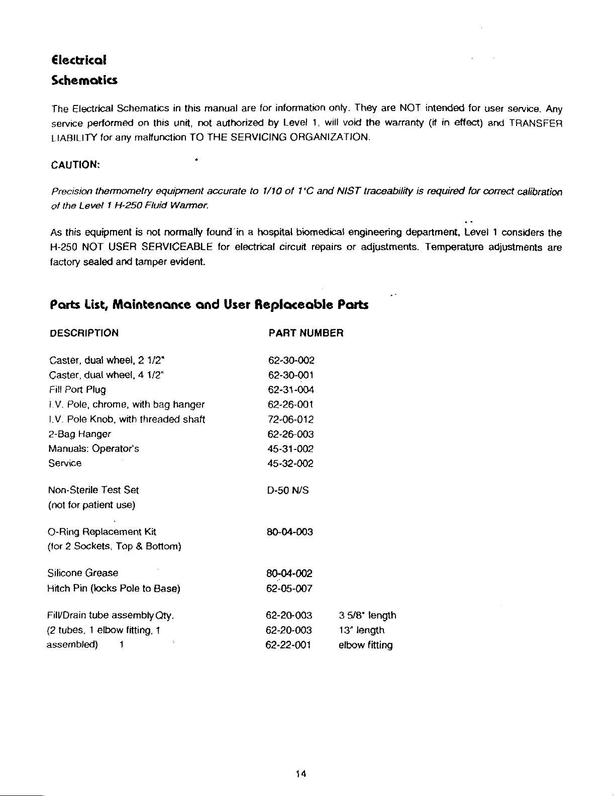
Electrical
Schematics
The
Electrical
service
LIABILITY
performed
for
Schematics
on
this
any
malfunction
in
this
unit,
TO
manual
not
authorized
THE
are
for
by
SERVICING
information
Level
1,
ORGANIZATION.
onty.
will
They
void
the
are
NOT
warranty
intended
(if
in
effect)
for
user
and
service.
TRANSFER
Any
CAUTION:
Precision
of
the
As
H-250
factory
Parts
thermometry
Level 1 H-250
this
equipment
NOT
sealed
List,
DESCRIPTION
Caster,
Caster,
Fill
LV.
IV.
2-Bag
Manuals:
Port
Pole,
Pole
Hanger
dual
dual
Plug
chrome,
Knob,
Operators
Service
equipment
Fluid
is
not
normally
USER
and
tamper
SERVICEABLE
evident.
Maintenance
wheel, 2 1/2"
wheel, 4 1/2"
with
bag
with
threaded
.
Warmer.
and
hanger
shaft
accurate
found
in a hospital
for
electrical
User
to
1/10
of
1*C
biomedical
circuit
repairs
Replaceable
PART
62-30-002
62-30-001
62-31-004
62-26-001
72-06-012
62-26-003
45-31-002
45-32-002
NUMBER
and
NIST
traceability
engineering
or
adjustments.
Parts
is
required
department,
Temperature
for
correct
calibration
Level 1 considers
adjustments
the
are
Non-Sterile
(nat
for
O-Ring
(for 2 Sockets,
Silicone
Hitch
FilVDrain
(2
tubes, 1 elbow
assembled)
Test
patient
Replacement
Grease
Pin
(locks
tube
Set
use)
Kit
Top & Bottom)
Pole
to
Base)
assembly
1
Qty.
fitting,
1
D-50
N/S
80-04-003
80-04-002
62-05-007
62-20-003
62-20-003
62-22-001
14
3
5/8"
13"
length
elbow
tength
fitting
Page 15

mm
一
一
oo
一
—
LHM
MS
LYOU
TAS
一
30d
y]
四
μ
m8
9
ma
isa
nevi
MS
30d
+
トーーーーーーーーーーー
НА
〇
+
a
i
=
라르
я
DAREI
NI
Ov
AMA
一
0d
4
一
|
Na8
чеки
GU
37891
|
-
+
3300
mg
、
-
【
Г
INI
8
vas
SKİ
INI
CAS
Td
|
ㅅ
70005
ong
Z
m
ak|
TU
>>
FE
一
o
a
S
s
一
OA
on
1945
M
SI
TTT
>
VASILE
MOOS
—
TULNON
Mv
Bd
TY
‘
,
TINOON
WO
YSN
OSZ-H
Y
MIGNON
48
NAYYO
TUL
va
Luva
é
06-87-01
0555204
140
—
aNYN
37026
ILIIHS
374
DNI
SJIOOTONHOU
TRAE
08
THA
308
sna
=
OTT
は
TIA/NYO
mu
div
8
LTUNO
oùn3
av
|
(Ha
Эви.
чипа
=
“TBA/NHO
=
ma
ENA)
—
AO-
8
=
Sditv
οςὉ
Za
ya
dna
10H
XY
1
à
è
-
r
EE
o
YINOULNOI
1
ng
a
aA
THA
ON
一
MA/
034
m8
o
AMO
sal
—
504
8
TA
BA
[sue
m8
8-1
IHL
Nag
OL
Zi
35n4
ce/1/€
0300Y
Y
A3Y
IVILN3014NOD
‘AlddNS
2GAOd
M
Page 16

Nte
O
'
Ate
1
MA
038
037
(as
SSSLMI
n
BylrNí
280
u
ry
νι
8
%
i
で
ВЫ
CHI
.03g
cos
037
tu
+39
OLr
gyiyNI
ZI
$
Azı*
Ngo
vas
031
ogy
68
-
VEDOZNIN
гп
gt
Ağlı
so
49001
cod
not
YI0YIH
SOd
Sr
G
08608
2g
OSZ—-H
BOSZH
OSZH
OYYOB
052-01-04
06-61-01
OSZOIOL
TOYLNOD/AUY
x
‘HIBNNN
AB
SAWN
IY
NAVY
13714
1HVd
©
veo
310
3714
NI
S2IDOTONND
EE
31
ow
zla
¿8
vid
2
9la
EM
HE
20021
2326
za
2xzs
ws
NECCRT
δρ
{
|
|
|
-
MOOL
ly
CLAIRE
Lari
|
4
LT
dy
20'0Z
sn
23030
1500
ar
7?
e
と
H3GY3H
I
'SOd
sr
£
vl
ey
za
#30vV3H
‘5092
er
y30Y3H
50d
ir
9
134208
Nid
ых
다
12008
Wa
νι
181
5109
Sx05
205
ID
Nid
8
asx
LMS
1
14205
Ni
art
nx
UJOvaS
dS9n
001
A0
NId
B
LMS
DE
IB
Nid&
GS
DaS
135008
Mee
nx
833005
2590
037
NO
Or-+
INN
sgzxOy-
ャ
io8
вхо
|
135205
мч
TNA
9;
Page 17

H-250
USA
Power
Module
FI
PUMP
AUX
TEMP
TB1
TH1
TH2
P1
K1
H1
SW1
SW2
PCB1
SW3
SW4
J1
J2
J3
J4
8
AMP
115VAC
EURO
CONTROLLER
8
TX1-81
TX1-81
12VDC
SPDT
600W
ALARM
FLOAT
ALARM\CNTRL
POLE
DIS INT
6
4
2
3
5
OUTLET
POS
115VAC
TEST
SW
INT
POS
POS
POS
POS
POS
ETA-R12DB3
PUMP
PWRDY
5CX-376FL
TERMINAL
+
THERMISTOR
THERMISTOR
POWER
RELAY
HEATER
SPDT
FLOAT
H-250
MICROSWITCH
MICROSWITCH
6
4
2
3
5
AC-1C-MD
8121LYZGE
SWITCH
ALARM\CONTROL
POS
AMP
POS
AMP
POS
AMP
POS
AMP
POS
AMP
8.0AMP
115VAC
43R033
BLOCK
SUPPLY
KUHP-5D51-12
600W
CON
CON
CON
CON
CON
MBK
TX1-81
TX1-81
115VAC
115VAC
10-782-PP
FLAT
ROUND
WHT
ILL.
12VDC
BOARD
.9A
60-23-002
66-01-002
60-45-002
60-13-001-A
60-47-010
60-06-00: で ーー
60-06-001
60-14-001-B
60-20-001
66-03-002-B
60-40-023
60-40-010
70-10-250
60-40-002
60-40-001
60-46-018
60-46-007
60-46-005
60-46-006
60-46-0038
©
ジリ
17
Page 18

|
0
mm
a
m
sa
wm
CI
[Г]
E]
|
m
AVONISSY
151
1081NOI/RYUV
1
Y
A34
mn
001094
ML
S1190
I
ασ]
+
O
の
w
n
TE
[
(Ej
)
on
ῃ
a
CC]
г
er
"C
+
cr
Ca
.
ul
二
и
w
u
y
・
+
a
LK
|
Пл]
1
as
и
u
ti
tl
sı
外
fan
|
re
EI
E
a
E]
a
|
e
NE
a
|
m
CI
NI
59
zf
10RH93」
1
13A31
145
tas
dl
3
“|
Y
-4
10
145
8
|
vos
If
a
ni
fas
=
vas
sn
+
sn
+
"O
ία
]
ta
[
и
ta
o
fay
10
ua
18
Page 19

H-250
R29
Ri
R28
R36
R27
R20
R19
R21
R22
R25
R26
R24
R23
R18
R15
R34
R35
R31
R30
R32
R16
R14
R7
R12
R10
R6
RH
R3
Rg
RS
RS
R4
R33
R2
C3
C2
CI
C5
C6
CR2
CR4
CR3
Qi
SD4
Alarm/Controt
15.4K
3K
11.0K
2K
15.4K
3.32K
3.32K
1.62K
10.0K
7.5K
10,0K
7.5K
10.0K
10.0K
51.1К
127.0K
1.0K
15.4K
2.0K
11.0K
8.2K
B.2K
8.2K
120.0K
8.2K
20.0K
20.0K
2.0K
470
470
470
470
10M
8.2M
10UF
10UF
.1UF
10UF
100РЕ
.
10UF
1N4148
1N4148
1N4148
2N4918
LED
GRN
Board
MF
1/8W
CF
1/4W
MF
1/8W
20
TURN
MF
1/8W
MF
1/8W
MF
1/8W
MF
1/8W
MF
1/8W
MF
1/8W
MF
1/8W
MF
1/8W
MF
1/8W
MF
1/8W
ΜΕ
1/8W
MF
1/8W
MF
1/8W
MF
1/8W
20
TURN
MF
1/8W
CF
1/4W
CF
1/4W
CF
1/4W
CF
1/4W
CF
1/4W
CF
1/4W
5%
CF
1/4W
5%
CF
1/4W
5%
CF
1/4W
5%
CF
1/4W
5%
CF
1/4W
5%
CF
1/4W
5%
CF
1/2W
5%
CF
1/4W
5%
25V
TANTALUM
25V
TANTALUM
POLY
25V
1KV
25V
1N4148
1N4148
1N4148
2N4918
GRN 4 PIN
CW20C104K
TANTALUM
CERAMIC
TANTALUM
PNP
1%
RNS5D
5%
1%
RN55D
SIDE
1%
RNS5D
1%
RN55D
1%
RN55D
1%
RN55D
1%
RN55D
1%
RN55D
1%
RN55D
1%
RN55D
1%
RN55D
1%
RN55D
1%
RNS5D
1%
RN55D
1%
RN55D
1%
RN55D
SIDE
1%
RN55D
5%
5%
5%
5%
5%
DISC
HLMP2500
ADJ.
POT.
ADJ.
POT.
MALLORY
MALLORY
OR
MALLORY
DD101
MALLORY
TDC
TDC
M20R104
TDC
TDC
60-01-001
60-01-022
60-01-019
60-01-024
60-01-001
60-01-004
60-01-004
60-01-010
60-01-003
60-01-002
60-01-003
60-01-002
60-01-003
60-01-003
60-01-007
60-01-005
60-01-006
60-01-001
60-01-024
60-01-019
60-01-011
06-01-011
60-01-011
60-01-013
60-01-011
60-01-014
60-01-014
60-01-023
60-01-025
60-01-025
60-01-025
60-01-025
60-01-017
60-01-021
60-02-001
60-02-001
60-02-003
60-02-001
60-02-002
60-02-001
60-03-001
60-03-001
60-03-001
60-04-002
60-10-006
19
Page 20

SD3
SD2
SD1
U3
U2
U4
US
U1
U6
J4
J2
45
Ji
Q1XN
U6SP
H250B
R17
R13
LS1
J3
Q1XB
U6SP
SDXS
SDXS
XSD
XSD
XU2
XU4
XU3
XU1
XU6
LED
RED
LED
RED
LED
RED
LM339N
ULN2003A
LM324N
MC78LO5CP
CM7555
LCD
3
POS.
HEADER
4
POS.
HEADER
5
POS.
HEADER
6
POS.
HEADER
NUT
4-40
LCD
SPACER
H-250 PC
BOARD
2.49K
10.0K
Al-256K
2
POS.
HEADER
BOLT
4-40X.25
LCD
SPACER
SPC
8PIN
SPC
BPIN
SKT 8 PIN
SKT 8 PIN
16
PIN
SOCKET
14
PIN
SOCKET
14
PIN
SOCKET
8
PIN
SOCKET
13
PIN
SOCKET
.181
.181
DIP
DIP
LED
GRN 4 PIN
LED
RED 4 PIN
LED
RED 4 PIN
LM339N
ULN2003A 7 INPUT
LM324N
MC78L05C0
CM7555
LCD
3
PIN
4
PIN
5
PIN
6
PIN'90
NUT
LCD
H-250
ΜΕ
CF
ALARM
2
PIN
BOLT
LCD
SPACER 8 PIN
SPACER 8 PIN
SOCKET 8 PIN DIP
SOCKET 8 PIN DIP
16
14
14
8
PIN
13
OR
OR
555
MODUTEC
90
AMP
90
AMP
90
AMP
AMP
4-40
HEX
SPACER
ALARM/CONTROL
1/8W
1%
1/4W
5%
AI-256K
90
AMP
4-40X.25
SPACER
PIN
DIP
PIN
DIP
PIN
DIP
DIP
SOCKET
PIN
SIP
HLMP2300
HLMP2300
QUAD
QUAD
5V
REGULATOR
TIMER
640457-3
640457-4
640457-5
640457-6
.395
RNS5D
640457-2
.395
.181.
.181
SOCKET
SOCKET
SOCKET
SOCKET
HLMP2300
MVOLT
COMPARATOR
DRIVER
OP
AMP
ICM
7555IPA
MTR
BIVAR
BIVAR
WIREWRAP
WIREWRAP
WIREWRAP
618-04
PC
618-04
808-187
808-187
WIREWRAP
WIREWRAP
WIREWRAP
BL100-301
BOARD
60-10-005
60-10-005
60-10-005
60-05-001
60-05-002
60-05-003
60-05-004
60-05-005
60-10-004
60-46-014
60-46-015
60-46-016
60-46-017
62-02-004
62-06-013
60-03-002
60-01-052
60-01-012
60-22-003
60-46-013
62-01-010
62-06-013
62-06-014
62-06-014
60-46-003
60-46-003
60-46-001
60-46-002
60-46-002
60-46-003
60-46-004
[Em
PSE
Po
ee
20
Mr”
re
ES
BASS
Foo)
Docoezoor
500.
04
003
©
Wy
So,
Sa
yo
2
>
~
Page 21

POLE
72-03
ASSY
001
-62-22-004
レン
©
62-314001
、
>
<
TT
一
Se
64-04-002
M
6401916 | |
62-01-015
ER
62-22-04
ue
~
、
121
62-01-012
62-01-0413
4
>
:|
©.
oder
—Y
121
com
——
>
6201-01)
‘
45-21-010
|
62-40-01
62-0113
—
17
«
64-10-00)
64-10-00]
-
45-21
-004
$2-30-002
Page 22

К.
ион
ZTE
200-b0-04
59
E”
8-200-20-9
100-40-24
—
|
‘a:
400-10-49
100-10-41
Xx
..
=.
|
юн
8-200-10-99
800-01-58
COBO
SL
210-62-29
Page 23

Mechanical
45-20-001
45-21-004
45-21-005
45-21-006
45-21-009
45-21-010
60-40-001
60-40-002
62-01-009
62-01-011
62-01-012
62-01-013
62-01-015
62-01-016
62-02-005
62-03-008
62-05-002
62-05-007
62-05-008
62-20-003
62-22-001
62-22-004
62-26-001
62-30-002
62-31-001
62-40-001
64-01-013
64-01-016
64-03-002
64-04-002
64-10-001
64-10-002
64-10-003
64-10-004
64-10-005-A
64-10-010
64-10-011
64-10-015
64-10-020
64-11-003-A
72-03-001
45-20-001
45-21-001
45-21-002
45-21-003
Parts
P,
LABEL
P,
LABEL
P,
LABEL,
P,
LABEL,
P,
LABEL
P,
LABEL
E,
SWITCH,
E,
SWITCH,
M,
BOLT
M,
BOLT
M,
BOLT
M,
BOLT
M,
BOLT
M,
BOLT
M,
NUT
M,
WASHER
M,
CLIP,
M,
HITCH
M,
LATCH,
M,
TUBING,
M,
FITTING
M,
FITTING
M,
POLE
M,
CASTER,
M,
CAP,
M,
O-RING
M,
BRACKET,
M,
BRACKET,
M,
BASE,
M,
POLE,
M,
SOCKET,
M,
SOCKET,
M,
SOCKET
M,
POLE
M,
POLE
M,
BALL
M,
DOWEL
M
,
BRACKET,
7M,
INSERT,
M
,
STUD
A,
|.
V.
P,
LABEL
P,
TAPE,
P,
LABEL
P,
LABEL
List
SET
BOTTOM
"SYSTEM
SCREW
FILTER
TOP
MICRO
MICRO
6-32 X .500
10-32 X 1.750
10-32 X 1.500
10-24 X .625
6-32 X .375
4-40 X .750
4-40
ESNA
1/4
BULLET
PIN
3/8 X 2
NO
POLY
SMC
SMC
ASSEMBLY,
DUAL
BASE,
310846
TOP
LATCH
H-250
FIBERGLASS
BOTTOM
TOP
CAP,
CAP,
BLACK
CLAMP
KNOB 1 7/8
PIN
INTERLOCK
POLE
SOLID
POLE
ASSY
SET
H-250
1/4"
ORANGE
DISPLAY
WATER
H-250
SOCKET
250"
COVER
"3"
SOCKET
ROUND
FLAT
FLT
BTN
FLT
FLT
FLAT
MS15795-811
AERO
LOCK-OUT
1/2"
KQL13-00
KQL13-36S
CHROME
WHEEL
BLACK
SWITCH
KEEPER
REV-
H.E.
H.E.,
H.E.
BLACK
DELRIN
BLOCK,
BLACK
1/8 X 5/8
CLAMP
H-250
H-250
LEVEL
-LS
"2"
LVR
HD
SKT
SKT
HD
HD
CLIP
FP321
H-250
BLACK
BLK
SWITCH
BLOCK
H-250
"1°
REV-12/5/88
BLACK
LVR
HDC/S
HD
SKT
UNION
MALE
SM 2 3/8"
2/1/89
BK
H-500/250-LS
V3L-2105-D8
V3L-101-D8
PHIL M/S
C/S
KNRLD
HD
PHIL
W/S
PHIL
WS
(-750DX.311DX.06TH)
ACG
ELBOW
ELBOW
7/8 X 42
REV-
9/9/86
REV-
9/9/86
WAS
2X2X47
DELRIN
DELRIN
DELRIN
3/4
WAS
WAS
WAS
WAS
DELRIN
BK4
WAS
BLK
WAS
„
1/2
1/2 X 3/8
W/RAMSHORN
WAS
WAS
RB0005
REV-A
REV-
REV-
PA0006
REB-B
DELRIN
MM0031
PA0044
NPT
4
PA0017
PA0016
PA0002
PA0003
PA0004
PA0011
WAS
PA0020
..
0687s
Fy
BH
KA
23
Page 24

45-21-0058
45-21-007
45-21-014
60-06-001
60-10-004
60-13-001-A
60-14-001-B
60-20-001
60-23-002
60-40-010
60-40-023
60-45-002
60-45-001
60-47-010
60-47-011
60-50-005
62-01-003
62-01-008
62-01-012
62-01-018
62-01-0719
62-01-020
62-01-022
62-01-027
62-02-001
62-02-005
62-02-006
62-05\010
62-06-003
62-06-015
62-07-005
62-07-006
62-20-001
62-20-003
62-22-001
52-22-010
62-22-012
62-22-020
62-26-001
62-31-004
62-37-001
62-40-007
64-01-001-B
64-01-018
64-02-002-B
64-07-007
64-10-008
P,
LABEL,
P,
LABEL
P,
LABEL,
E,
THERMISTOR
E,
LCD,
E,
TEMP
E,
POWER
E,
RELAY,
E,
CIRCUIT
E,
SWITCH,
E,
SWITCH
E,
OUTLET,
E,
PLUG,
E,
TERMINAL
E,
TERMINAL
E,
WIRE
M,
BOLT
M,
BOLT
M,
BOLT
M,
BOLT
M,
BOLT
M,
BOLT
M,
BOLT
M,
BOLT
M,
NUT
M,
NUT
M,
NUT
M,
BOLT,
M,
STANDOFF
M,
RAIL,
M,
STRAIN
M,
TYWRAP,
M,
TUBING,
M,
TUBING,
M,
FITTING
M,
FITTING
M,
FITTING
M,
FITTING 1/8-27NPT
M,
POLE
M,
PLUG,
M,
GASKET
M,
SEAL
M,
CHASSIS,
M,
BRACKET,
M,
ENCLOSURE,
М,
WATER
M,
FILLPORT
“SYSTEM
POWER
SOCKET
MODUTEC
CONTRLR
SUPPLY,
SPOT
BREAKER
FLOAT | 10-782-PP
C&K
EURO
HOSPITAL
14AWG
10-32 X .375
6-32 X .375
10-32 X 1.500
8-32 Χ .500
#8 X .500
6-32 X .250
10-32 X .750
8-32 X .375
10-32
4-40
ESNA
6-32
ESNA
POLYCARBONATE
TERMINAL
RELIEF,
X-LARGE
1/4 X
POLY
SMC
SMC
SMC
ASSEMBLY,
FILLPORT,
PVC
SW
APM
PWR
PC
TANK,
BLOCK,
250°
OUTLET
AUX.
TX1-81
MVOLT
5CX-376FL
12V,
W389CX-2
SPDT
AUXILIARYPWRDY
GRADE
BLOCK
STOP
3CON
PAN
PAN
PAN
PAN
SKT
SKT
ESNA
0.250
BLOCK
STRAIGHT
3/8
CVT
1/2"
KQL13-00
KQL13-35S
KQH13-35S
"T"
CHROME
RED
2X4
VF10212
N5040-R
MOD
BOARD
H-250
H-250
BLACK
-LS
REV-12/5/88
OUTLET
SENSOR
MTR
.9AHA15-0.9-A
MAGNACRAFT
8
AMP
3120-F323-P7T
8121LYZGE
HUBBELL
PHX
MBK
PHX
E/MBK
SJT
ORANGE
SKT
HD
PHIL
SKT
HD
C/S
PHIL M/S
PHIL
S/M/S
PHIL M/S
HD
C/S
HD
HEAD
SSL
1/4
FR
PHX
THRU
TY29M
OVERFLOW
UNION
MALE
MALE
W/BARBS,
7/8 X 42
THREADED
FOR
H-250
REV-B12/18/89
H250REV-
REV-B
ROSE
REV-B
DELRIN
H-500/250-LS
BL100-301
43R033121-250
8215-C
LINE
HD
M/S
KNRLD
FOR
ROSE
NS
15
SR7L-2
ELBOW
ELBOW
CONNECTOR
BLACK
W/
1/2
C&K
SWITCH
2/1/89
WAS
MM0031
1-R12DB3
CORD
ENC
HEYCO
1/2
1/2 X 1/4
NYLON
RAMSHORN
NPT
WAS
WAS
PM0046
86333-1
64-02-002
#1250
NPT
1/2X1/4NPT
4
P-48B
MM0005
MM0006
BH
24
Page 25

4
“So
64-10-012
64-10-013
64-10-014-B
64-10-016
6601-002
66-03-002-B
70-01-004
70-01-005
70-02-002
70-03-002
70-04-002
70-04-003
72-05-002
72-06-007
72-06-017
72-07-001
72-08-003
=
74-01:008—
74-02-002
74-05-002
M,
FILTER
-
M,
BRACKET,
M,
THERMISTER
M,
MOUNT,
E,
PUMP
E,
HEATER
A,
CIRCUIT
A,
LINE
A,
ALARM/CONTROL
A,
POWER
`
A,
FLOAT
A,
ALARM
A,
WATER
A,
TERMINAL
À,
FILTER
À,
CABINET
A,
FILLPORT
A,
PUMP
A,
HEATER
A,
POWER
BLOCK,
ALUMINUM
BACKING
BLOCK
FLOAT
AC-1C-MD
120V
SWITCH,
115V
600W
BLK
BREAKER HARNESS
CORD
ASSY
BOARD
SUPPLY
SWITCH
SWITCH
TANK
BLOCK
BLOCK
ASSY
BLOCK
ASSY
ASSY
ASSY
ASSY
ASSY
ASSY
H-250
H-250
ASSY
H-250
H-250
H-250
MODU
BLACK
PLATE
1/4NPT
1X1
ANODIZED
DELRIN
H-250
CENTRIFICAL
WHT
GRN
H-250
H-250
H-250
H-250
H-250
H-250
H-250
REV-B9/27/89
25
Page 26

HAAL'YWARE
STANDARD
PROCEDURES
РЕК
ЕСО # 157
‘scription
{-250
(DOM/
CALIBRATION
8.
9.
10.
CHECK
8.1
SET
9.1
9.2
9.3
9.4
COLD
10.1
10.2
10.3
FLOAT
TO
CHECK
ALARM
UNIT
TURN
ASMALL
ALLOW
SET
UNIT
START
TURN
PLACE A CLAMP
NEUTRAL).
TURN
AT
39.2
OPERATING
INT)
SWITCH
FLOAT
SOUNDS.
AT
39.9
TEMP.
TURN
TIME
TO
UNIT
UNIT
CONTROLLER
RUN
OFF.
SET
ON.
+-0.3°C
HSOP#
FINAL
PROCEDURE
SWIT:
REFILL
FOR
DOMESTIC
OF
THE
TO
STABILIZE
AT
39.9°C
REPLACE
CURRENT
METER
THE
UNIT,CURRENT
FOR
DOMESTIC
WATER
AND
POT
POT
IS A LARGE
TEMP.
+-
0.1°C
WARM
METER
ON 6 AMP
AND
002
De
ONNECT
TO
RE-OPERATE.
40.9
CW
TO
BETWEEN
FOR
WATER
AROUND
RANGE.
40.2
BERN
novo“
FILLPORT
FOR
INCREASE
INCREASE
DOMESTIC
SHOULD
+-
Ne
TUBING
INTERNATIONAL;
TEMPERATURE
IN
ADJUSTMENTS.
AND
WITH
COLD.
ONE
CHANGE
OF
ey
TEMP.
40.9°C
THE
FR
ENG:
QC:
МЕС:
07/25/95
AND
+-0.1°C
CIRGUIT
Date
DRAIN
BREAKER
NAL
NAL.
File
Name:
WATER
FOR
INTERNATIONAL.
WIRES
JANT
DRAW
HSOP002.DOC
UNTIL
(LINE
TO
Page
2
of
WATER
OR
PULSE
EV
2
LEVEL
MODE
11.
11.1
IDLE
:21
13.
SEND
CHECK
REMOVE
RATE
CHECK
ALLOW
FOR
UNIT
FLOW
RATE
CALIBRATED
OF
THE
CIRCULATING
UNIT
TO
RUN
INTERNATIONAL.
TO
Q.A.
FOR
ELECTRICAL
T-40
THERMO
WATER,
FOR 1 HOUR
x
Y
V
TESTING
URE
AND
39.9°C
+-
FINAL
A
ALLONS
0.1°C
FOR
INSPECTION.
FLOW
PER
RATE
MINUTE.
DOMESTIC
METER.
AND
40.9°C
THE
+-
FLOW
0.1°C
Page 27

«LARD
OPERATING
PROCEDURES
PER
ECO # 157
scription
250
(DOM/
INT)
CALIBRATION
1
SET
UP
11
2.
3.
1.2
1.3
14
CHECK
2.1
CHECK
3.1
3.2
RECORD
THE
NOTIFY
FILL
INSTALL
RECORD
WORKSHEET.
TURN
PLACE
MEASUREMENT
ADJUST
THE
FOLLOWING
YOUR
UNIT
WITH
THE
THE
FOR
LEAKS
UNIT
POWER
DC
VOLTAGE
POWER
ON.
HSOP#
FINAL
PROCEDU
Qe
RESUL
TEST
PARAMETERS
SUPERVISOR.
TAP
WATER.
CALIBRATED
CALIBRATED
(H.S.O.P.
OBSERVE
SUPPLY
SHOULD
SUPPLY
002.5).“ALSO
VOLTAGE
METER
OUTPUT
Pe
READ
FOLLOWING
T40
THERMOMETER
ALL
FITTINGS
LEADS
002
que"
ass
TAG
THERMOMETER.
RECORD
'
AND
ACROSS
12
VOLTS
IF
NECESSARY.
THE
+-
THE
0.1
À
ON
H.S.O.P.
MACHINE
SERIAL
THE
SEAMS
PCB
VOLTS.
νο
#,
AMBIENT
IN
CONNECTOR
Date
07/25/95
002.5
IF
THE
WITH A DESCRIPTION
YOUR
NAME,
TEMPERATURE.”
THE
CIRCULATING
(J5),
UNIT
AND
BLACK
File
UNDER
THE
WATER
Name:
OF
DATE
AND
HSOP002.
TEST
THE
ON
SYSTEM
RED
Page
Tof
2
DOC
FAILS
TO
FAILURE
THE
CALIBRAT
FOR
WIRES,
MEET
AND
LEAKS
THE
4.
SET
OVER
4.1
WATER
4.2
ADJUST
TEMP.
TEMPERATURE
INTERNATIONAL.
3
ADJUST
..4
ADJUST
AT
4.5
ADJUST
41.5
4.6
REPEAT
5.
SET
CALIBRATION
5.1
COMPARE
5.2
TURN
THERMOMETER
6.
POLE
6.1
CHECK
UNIF
RETURN
6.2
TO
ACTIVATE.
7.
ALARM
7 1 DEPRESS
PL
ASHING
OPERATIONAL.
THE
40.2
+-0.2°C
THE
+-
0.0° C FOR
STEPS,
THR
INTERLOCK
TOP
SHOULD
CHECK
TEST
ALARM
MUST
THE
40
ADJ.
POT
THE
OVERTEMPERATURE
40
ADJ.
POT
FOR
DOMESTI
40
ADJ.
POT
DOMESTI
TWO
TIMES
OF
DISPLAY
UNIT
LCD
TO
40
AN}
POT
ON
LCD
+-
0.0°C.
SWITCH
SOCKET
SOCKET
POLE
RETURN
SWITCHES
ALARM
AND
NOT
ALARM.
TO
INTERLOCK
HEAT
TEST
THE
WHILE
LATCHED
SWITCH
ALARM
BE
AT
SO
THE
LCD
CL
CO
C
440
Nr
CALIBRATED
PCR
SO
THAT
TEST
I.ATCHED
RELEASE
POSITION.
SPRING
EXCHANGER
AND
MUST
ВЕ
LEAST
39.5
READS
DEG
44.
.
AND
*-
0.0°C
FOR
THE
ACTIVATION
THERMOMETER
THE
UNIT
DOWN.
LATCH
HEAT
INTO
THE
GRASP
AND
UNIT
SHOULD
EXCHANGER
INTERLOCK
GREEN L ne
ее
(C)
TO
+
DOMESTIC
x
E
ALARM
CONFIRM
FOR
INTERNATIONAL.
CONFIRM
INTERNATIONAL.
DISPLAY.
LCD
IS
FIRMLY
SOCKET
BE
OUT
AND
agi
THAT
TIHAT
AND
EQUAL
AND
UPWARDS.
OPERATIONAL.
OF
THE
TURN
νο
PROCRED
WITH
AND
42.0
SOUNDS.
THE
ALARM
THE
ALARM
DEACTIVATION
TO
THE
CALIBRATED
MOVE
INTERLOCK
UNIT
ALARM
OFF.
IN
SHOULD
ALL
THE
ALL
SHOULD
THE
RED
SYSTEM
TEST.
+-
0.0°C
FOR
DEACTIVATES
ACTIVATES
POINTS.
DIRECTIONS.
ALARM
BECOME
LED'S
SHOULD
AT
ACTIVATE.
SHOULD
OPERATION
SHOULD
BE
BECOME
LEVE!
 Loading...