

Smiths LST Caspian 60 Series, LST Caspian 150 Series, LST Caspian 180 Series, LST Caspian 90 Series, LST Caspian 120 Series Installation & User Manual
Page 1
Accessories
By fitting optional equipment this product can operate automatically under normal running
conditions. The optional controls fit within the casing of the unit and are supplied with easy to fit
instructions.
Wall Mounted Controller WMCEC
This enables the end user to control the fan speed from a wall mounted control.
Plinth to suit Caspian Universal CCLP
Where the product is installed floor level, the plinth will raise the unit 150mm above the
floor. (Available in black & white)
Air inlet filters for all models.
For accessories or spares please contact either your supplier or Smith’s Environmental
Products Ltd.
Technical designation 60, 90, 120, 150, 180 LST
Products with this symbol (crossed out wheelie bin) cannot be disposed as household waste.
Old electrical and electronic equipment must be recycled at a facility capable of handling these
products and their waste by-products. If you are purchasing replacement equipment your
retailer may offer a 'take back' scheme, or will be able to give details of the nearest approved
authorised treatment facility. Proper recycling and waste disposal will help conserve resources
whilst preventing detrimental effects on our health and the environment.
WEEE Registered Code : WEE/ED0093VW
For Ireland (Republic & Northern), contact MT Agencies on 00 353 1 864 3363
In light of our policy of continuous development Smith’s E nvironmental Products Ltd reserve the right to alter
specifications without prior notice.
Iss: 5 8 OCT 17
Suitable for Low Level Installation Only
Installation & User Guide
User Information.
This appliance can be used by children aged from 8 years and above and
persons with reduced physical, sensory or mental capabilities or lack of
experience and knowledge if they have been given supervision or
instruction concerning use of the appliance in a safe way and understand
the hazards involved. Children shall not play with the appliance. Cleaning
and user maintenance shall not be made by children without supervision
A means for disconnection from the supply mains having a contact
separation in all poles that provides full disconnection under overvoltage
category III conditions must be incorporated in the fixed wiring in
accordance with the wiring rules.
Ensure that the fan convector is switched-off before opening the cover.
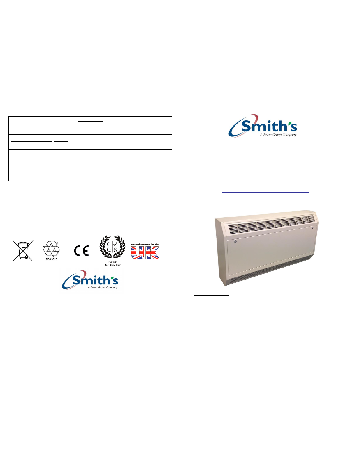
LST Caspian
60, 90, 120, 150 & 180
Series Fan Convectors
Smith’s Environmental Products Ltd
Blackall Industrial Estate, South Woodham Ferrers, Chelmsford , Essex, CM3 5UW
Tel: 01245 324900 Fax: 01245 324422
Sales: sales@SmithsEP.co.uk General Information E -mail: info@SmithsEP.co.uk Web: www.SmithsEP.co.uk
Page 2

Introduction
Testing undertaken by BSRIA conforms these heaters comply with DHSS Engineering and
Data DN4 and NHS Estates Health Guidance Note ‘Safe Hot Water and Surface
Temperature’ (1998).
These heaters are designed as a low level mounted product with air outlet discharge from the
top of the unit. LST function ensures the surface and grille temperature does not exceed 43°C
by measuring leaving air temperature and modulating the flow through the heat exchanger.
These heaters must not be installed in wet rooms or other high humidity areas.
These heaters are designed for use on standard two-pipe pumped central heating systems
with a maximum water temperature of 86° C and a maximum pressure of 6 bar (88lbs/in²).
Pipe connections are 22mm, Flow direction must follow that shown on the body of the
valve.
These heaters are classified as a fixed appliance and the electrical connection should be via a
3A fused spur. The fused spur must not be directly below the heater but should be accessible
after completion of the installation. All heaters must be earthed.
This heater is fitted with an integral room thermostat.
This heater is fitted with an air outlet thermostat pre-set to 34°C; and should not be adjusted
above 35°C.
To avoid the possibility of vibration these units must be fitted to a flat even surface.
These heaters are fitted with low temperature cut out stats and will not operate until a water
temperature of approximately 35°C is achieved.
If desired a remote room thermostat can be used in conjunction with this heater. Refer to the
manufacturer’s instructions supplied with the thermostat.
Please note the guarantee may be invalidated if this product is not installed and used in
accordance with these instructions.
For further details please contact our Technical Support on 01245 324560.
Installation Guide
1. Unlock and lower the front access panel using the keys supplied.
2
Fault Finding
1. The fan does not run on any speed setting.
a. Check the power supply is switched ON.
b. Check the fuse in the fused spur.
c. Check the wiring at the fused spur.
d. Check thermostat is calling for heat
e. Check the central heating is switched ON and hot water flowing through system.
f. Vent any trapped air from the system (with the heating system turned OFF).
2. No heat output.
a. Vent any trapped air from the system (with the heating system turned OFF).
b. Check the central heating is switched ON and hot water flowing through system.
c. Check thermostat is calling for heat
d. Balance the central heating system if installed on the same circuit as panel radiators and
increase the circulating pump speed if required.
e. Increase the boiler water temperature.
Providing the power supply is switched on and the room thermostat is calling for heat the
heater will switch on and off automatically with the central heating system.
In the event of difficulty please contact our technical help-line on 01245 324560. It would be
helpful if you do not disconnect the heater from the central heating system prior to calling.
Maintenance.
Warning! Isolate from the electrical supply before performing any work on the
unit.
The internal air filter is removable for servicing. To gain access to the filter, unlock and lower
the front access panel, remove the 2 screws from the filter enclosure panel and lift out.
Carefully lift and remove filter (see fig 3). The filter should be gently tapped to remove any
accumulated dust and vacuumed if necessary.
The coil fins are delicate so take care and only use a soft brush or vacuum cleaner to remove
any dust that may have accumulated.
To replace filter, reverse the removal instructions and ensure the lower front access panel is
securely locked.
The fan(s) and motors should not require servicing. Please contact your supplier if damaged.
Please note in the event of an engineer’s visit, Smith’s Environmental Products Ltd reserve the
rights to apply a call-out charge should the fault prove to be with the system or installation and
not the heater appliance.
7
Page 3

VR2
VR1
L.T.C
Mains Supply
FAN
+10V
Control
Ground
Tacho
Speed Control
FAN
VR2
VR1
L.T.C
Mains Supply
+10V
Control
Ground
Tacho
Speed Control
FAN
E
N L
LTC FAN
M VALVE
S
W
DIGITAL
ROOMSTAT
BYPASS
TUBE
1 2 3 4 5 6 7 8 9
E N L
VR2
VR1
L.T.C
Mains Supply
+10V
Control
Ground
Tacho
Speed Control
Note: The e arth li nk is d irectl y
above the ne gative termina l
on th e EC D C filte r.
FAN
E N L
S W
DIGITAL
ROOMSTAT
BYPASS
TUBE
1 2 3 4 5 6 7 8 9
M VALVE
LTC FAN
E N L
Fig 3
6
2. Fix the unit to the wall via suitable fixings.
3. Connect the heating system flow and return pipes to the heater pipe work. Pipe entry/ exit
can be made through either the back of the unit or by using the Pipe Knockouts on the bottom
of the unit (See Fig 3). Do not use soldered fittings to connect the heater pipe work as the heat
generated may cause damage to internal wiring and components.
We recommend the use of full-flow service valves. The valves should be accessible after
completion of the installation. We also advise the fitting of an air vent at the highest point on
either the flow or return pipe to remove any air trapped within the system.
4. Open the full flow service valves (see above) and check for water leaks. Remove any
trapped air from the unit via the built in bleed screws as shown in the diagram below.
Note: Ensure the motorised valve is set to the Auto position.
5. Isolate the electrical supply
245
66
176
660
274
A
Model A
60 595
90 895
Electrical supply
in this side
Pipe Centres
B
480
45
Fix to wall using
suitable fixings
B
470
770
85
150
120 1195 1070
150
1495 1370
180 1795 1670
3
Caspian CL 60
Wiring Diagram
Caspian CL 90/ 120
Wiring Diagram
Page 4

6. Connect the power supply from the fused spur (3 Amp) to the heater terminal block marked
Supply E N L (see fig 2) via the cable entry hole in the top chassis of the heater.
The fused spur must not be directly below the heater and must be accessible after the
installation is complete. All electrical work should be carried out in accordance with current
IEEE regulations.
7. To connect a room thermostat (not supplied) to the connection block on the heater remove
link and connect to terminals 7 & 8.
For further information refer to the room thermostat manufacturers instructions.
Fig 1
Commissioning
1. Turn on the electrical supply at the fused spur.
2. Turn the thermostat control (if fitted) to maximum.
3. Turn on the central heating system
4
4. If these heaters are installed on the same circuit as panel radiators balance the central
heating system.
5. If the installation is working correctly remember to reset the thermostat control to its required
setting.
6. Set the fan speed control to the desired position (see fig 2)
(Note To decrease motorised valve cycles it is recommended that the flow is reduced. (Please
ensure adequate flow through heater).
7. Lift up and close front access panel, ensure this is secure and locked in place with keys
provided.
8. Please leave this Installation & User Guide with the user for future reference.
Heating – see below
Ensure the central heating system is ON. Switch on the power supply to the unit. Set the
thermostat control (if fitted) to the desired temperature. Providing the water temperature
in the central heating system is more than 35°C and the thermostat (if fitted) is calling for
heat the product will switch on.
Note: Achieving higher output than shown in the above table will not be
possible by increasing flow rate, this is because due to LST function of the
heater. To achieve higher than shown outputs increase fan speed.
It is recommended that the model chosen is capable of maintaining the calculated heat loss at
medium heat output enabling the high speed setting to be used for faster heat up and the low
speed for maintaining temperature.
5
Heat Output Performance
LST
Model
Heat
Output
(kW)
Heat
Output
(kW
Heat
Output
(kW
High
Medium
Low
60
2.16
1.58
1.00
90
3.94
3.46
2.99
120
5.71
5.35
4.98
150
7.20
6.70
6.20
180
8.7
8.2
7.7
LOW
MED
HIGH
Fig 2
Heat outputs based at 80°C mean water
temperature, with an entering air temperature
of 20°C, in accordance with BS EN442.
Page 5

Guarantee Statement
Thank you for purchasing a Smith’s heater.
It has been designed and manufactured to the highest quality standards to ensure it
gives you efficient and trouble-free service for many years.
To back up our commitment, included with your product is a free five year parts
and labour guarantee.
This gives you peace of mind that in the unlikely event of the product failing within
the first five years, we will repair or replace the product completely free of charge
provided the product has been installed, used and maintained in accordance with the
instructions.
It is important to register within 7 days. This will ensure you receive a prompt and
efficient service, if your product requires attention within the guarantee period. If
you do not register your product, you will be required to produce a proof of purchase
prior to receiving this service.
If you experience any problems with the use of your product, please contact our
after-sales office on 01245 324560.
Smith’s Environmental Products Ltd manufactures a complete range of heaters for
domestic and commercial applications.
If you require any further information, please contact us on 01245 324900 or visit
our website at www.SmithsEP.com.
Your statutory rights are not affected by this guarantee.
Please pull this registration card from the
booklet and fill in all parts and return.
Page 6

Guarantee Registration Card
& Customer Satisfaction Survey
Dear Customer
We hope our product suits all your requirements; it would help us immensely if you could find the time to
fill in this form, your response will help us maintain the quality standards we all expect in today’s climate.
Customer name ________________________________________ Date_____/_____/__________
Email Address ____________________________@________________________________________
Product Name ______________________________________________________________________
Tick as appropriate
V Good Good Fair Poor
Product
Delivery
Sales & Ordering
Response to
any problems
Comments …………………………………………………………………………………………………
………………………………………………………………………………………………..
………………………………………………………………………………………………..
Thank you for your time to fill in this survey, the response will help us to serve your
needs more effectively. Please return by fax to 01245324422.
Quality Control Manager: Ron Brown ron.brown@smithsep.co.uk
User Details
User Name Mr/Mrs/Miss/Ms/Other ……………………………………………………………………………
Initials …………………. Surname ………………………………………………………………………………
Address ………………………………………………………………………………………………………………….
………………………………………………………………………………………………………………………………
…………………………………………………………………… Post Code: …………………………………
Telephone: ……………………………………………………………………………………………………………..
Product & Model installed (e.g. Space Saver SS5)
……………………………………………………………………………………………………………………………….
Room Installed (e.g. Kitchen): …………………………………………………………………………………..
Your details will only be held by Smiths Environmental Products Ltd and used solely to
provide customer services and product information.
If you do not wish to be contacted, please put an x in the box.
Installer Details
Company name: …………………..
Principal contact: Mr/Mrs/Miss/Ms/Other: …………………………………………………………………
Initials: ………………… Surname: ……………………………………………………………………………
Address: …………………………………………………………………………………………………………………
………………………………………………………………………………………………………………………………
…………………………………………………………………… Post Code: ……………………………………
Telephone: …………………………………………………………………………………………………………….
Date of installation ……………/……………/………………
Room Installed (e.g. Kitchen): …………………………………………………………………………………..
Your details will only be held by Smiths Environmental Products Ltd and used solely to
provide customer services and product information.
If you do not wish to be contacted, please put an x in the box.
 Loading...