

Page 1
Page 2
Introduction /
Specifications
Sub-Assemblies
Technical Description
Disassembly Procedures
Maintenance, Testing
and Calibration
®
Troubleshooting
Spare Parts
Rounding Off
Appendix 1Circuits
Appendix 2 PCB Layout
Blood and
Fluid Warmer
Appendix 3 Symbols Glossary
Appendix 4 Frequently Asked Questions
Information Bulletins
Page 3
Welcome...
Who are we?
medical devices for treating critically ill patients. These devices may
be used in high-risk situations, and include ambulatory and hospital
PREFACE
Welcome...
... to one of
Smiths Medical’s
Technical Service Packs
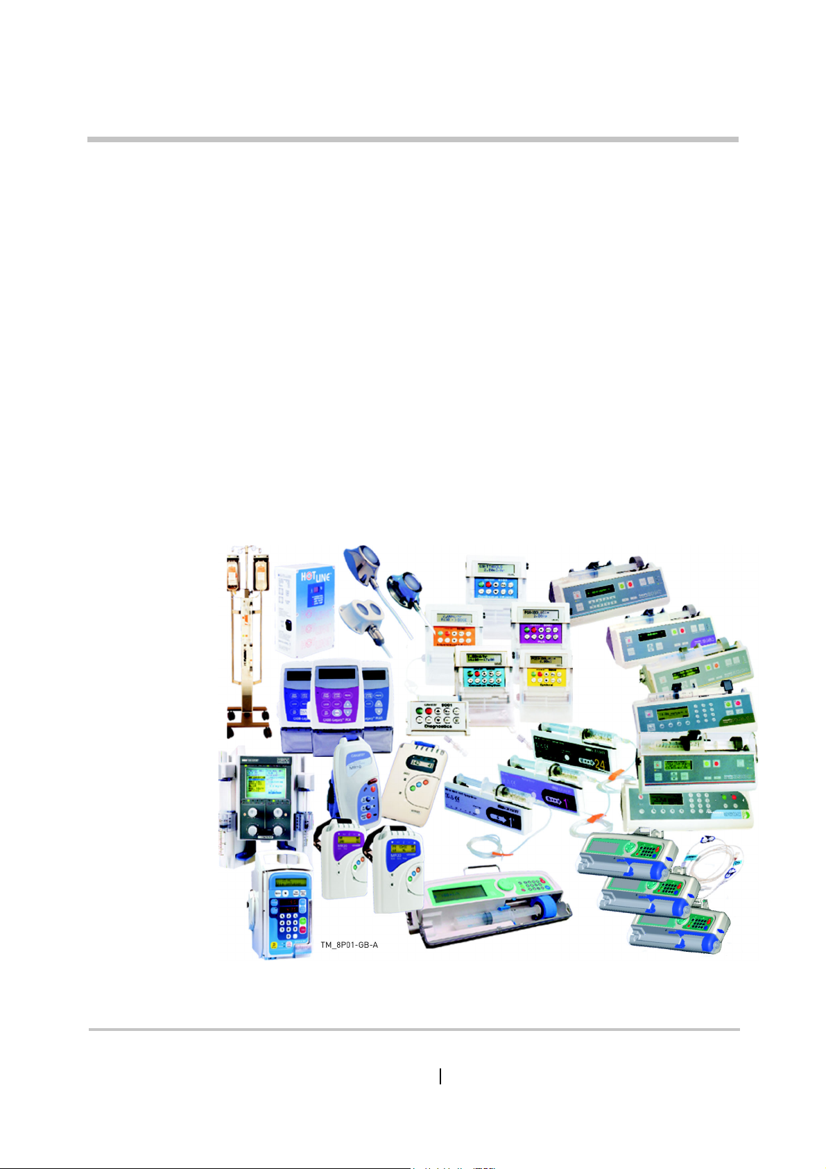
Smiths Medical is a global manufacturer and supplier of
infusion pumps, neo-natal and paediatric monitors, blood and fluid
warmers, and convective warming systems for patients.
Figure P - 1: A selection of Smiths Products - old and new
HOTLINE® Blood and Fluid Warmer Technical Service Pack i
Page 4

Smiths Medical has a long history, bringing many well known
brands to the market, such as Portex®, Level 1®, BCI®, Graseby®,
Wallace®, Bivona®, Pneupac®, Deltec®, DHD® and Medex® . It is part
of the Smiths Group, a British engineering consortium founded in
1851.
Now all of these formerly independent business units have
been merged into one Global company — Smiths Medical. Smiths
Medical is a world leader in the design, manufacture and
distribution of medical devices.
What about Level 1®?
The Level 1® range of products is synonymous with a high
PREFACE
Welcome...
quality, cost effective range of temperature management products.
The range includes blood and fluid warming products for both
gravity flow and fast flow intravenous or irrigation applications, and
convective (hot air) warming systems. These products help to
prevent hypothermia and maintain normothermia in patients
undergoing surgery in the operating theatre, recovery ward and in
the casualty departments in emergency situations.
Why is Temperature Management important?
Patients undergoing surgical procedures are exposed to a
variety of influences that have a effect on their ability to maintain
their normal body temperature (Normothermia). If these factors
persist for a prolonged period of time, the patient will become
hypothermic, i.e., their body temperature drops below 36°C. Even
mild hypothermia (34°-36°C) puts patients at risk. Trauma cases and
extensive procedures present well-known temperature
management challenges. But so can routine operations. Clinical
evidence shows that warming is important in any case lasting more
than an hour and/or using more than one litre of fluid.
HOTLINE® Blood and Fluid Warmer Technical Service Pack ii
Page 5

PREFACE
What hypothermia does to the patient
■ Cardiovascular instability
■ Vasoconstriction, decreased cardiac output, and changes in
electrical conduction can contribute to an increased incidence of
cardiac ischemia, arrhythmias, and arrest.
■ Increased coagulopathy
■ Coagulopathy may result in increased bleeding, possibly
necessitating blood transfusions.
■ Altered action and reduced clearance of anesthetics
■ Hypothermia decreases a patient’s metabolism, resulting in a
need for higher amounts of anesthetics. It also contributes to
delayed emergence from anesthesia and longer recovery room
stays.
Welcome...
■ Increased risk of wound infection
■ Wound infection and delayed wound healing result in longer
hospital stays. Wound infection can prolong hospitalization.
■ Postoperative discomfort
■ Thermal discomfort, shivering, and fatigue can occur when core
temperature decreases by 1°C .
The HOTLINE® Blood and Fluid Warmer
The HOTLINE® Blood and Fluid Warmer uses a special
disposable that totally encloses the patient’s end of the IV
administration set in a bath of warmed recirculating fluid. This
means that the IV fluid is introduced at or above core body
temperature, rather than in the chilled state that it may have been
stored at.
This simple solution eliminates the chill being passed to the
patient, and assists the patient’s own efforts at maintaining
normothermia.
HOTLINE® Blood and Fluid Warmer Technical Service Pack iii
Page 6

Published by:
Smiths Medical ASD, Inc.
160 Weymouth St, Rockland, MA 02370, USA
■ For assistance or further information, contact Smiths Medical
USA/ Canada
■ Smiths Medical ASD, Inc.
■ USA/Canada 1-800-258-5361
PREFACE
ASD, Inc., Technical Service Department or your Smiths Medical
ASD, Inc., distributor at:
160 Weymouth Street, Rockland, MA 02370 USA
International +1-781-878-8011
Welcome...
European Representative
■ 6PLWKV«0HGLFDO«,QWHUQDWLRQDO«/WG
%UREKA0ARK,OWER0EMBERTON
!SHFORD+ENT4."&5+
5HJLVWHUHG«LQ«(QJODQG«1XPEHU««
■ 7HO««««
Australian Representative
■ Smiths Medical Australasia Pty. Ltd.
61 Brandl Street, Brisbane Technology Park
Eight Mile Plains, QLD 4113, Australia
■ Tel +61 (0) 7 3340 1300
Fax +61 (0) 7 3340 1399
World WideWeb:
■ www.smiths-medical.com
HOTLINE® Blood and Fluid Warmer Technical Service Pack iv
Page 7

PREFACE É Welcome...
■ All possible care has been taken in the preparation and production
of this publication, but Smiths Medical accepts no liability for any
inaccuracies that may be found.
■ This publication may be subject to revision and it is the user’s
responsibility
appropriate to the intended use.
■ Users of the equipment must ensure that they have read and
understood the contents of the complete manual including the
warnings and cautions and have been trained in the correct use of
the product.
■ This publication has been compiled and approved by Smiths
Medical for use with their respective products.
■ It may be supplied in a format that permits users to access the text
and illustrations for their own use (e.g., training and educational
purposes). Smiths Medical cannot be held responsible for the
accuracy of, nor any resulting incident arising from, information
that has been extracted from this publication and compiled into the
user’s documentation.
to ensure that the correct version is used
■ Other than as herein noted, no part of this publication may be
reproduced, transmitted, transcribed, or stored in a retrieval
system or translated into any human or computer language in any
form or by any means without the prior permission of Smiths
Medical.
■ “Graseby
trademarks of the Smiths Medical family of companies. All other
trademarks are acknowledged as the property of their respective
owners.
■ The symbol
Trademarks Office and in certain other countries.
®
” “Smiths” “HOTLINE®” and “LEVEL 1®” are all
® indicates it is registered in the U.S. Patents and
© 2011 Smiths Medical family of companies.
All rights reserved.
HOTLINE® Blood and Fluid Warmer Technical Service Pack v
Page 8

Revision History
PREFACE É Revision History
Issue
No:
000 New Revision - First Release All July 2006
001 Updated EU Rep address iv, v, vi, 6,
Reason for Change Pages
Affected
front and
back covers
Date
October 2011
HOTLINE® Blood and Fluid Warmer Technical Service Pack vi
Page 9

Aims
PREFACE Aims
To provide technical engineering support staff with the
practical and theoretical knowledge necessary to ...
■ ... diagnose,
■ maintain,
■ repair,
■ and update ...
... Smiths Medical products as appropriate to meet the needs
of your healthcare establishment’s equipment management
protocols.
HOTLINE® Blood and Fluid Warmer Technical Service Pack vii
Page 10

Objectives
a qualified Biomedical Engineer or Technician with appropriate
experience to successfully tackle any repair or component
replacement required, and recalibrate the unit either routinely or
post-repair work.
training course that can be held either at Smiths Medical’s premises,
or at your own establishment if that would be more convenient.
Successful training course attendees may be certified by
Smiths Medical, an option not open to non-attendees. Please
PREFACE Objectives
This manual will give you the necessary information to enable
The material covered by this manual is also offered as part of a
contact your local Smiths Medical distributor for more details. We
strongly recommend course attendance wherever possible, to
ensure the highest standards of maintenance for your HOTLINE®
units.
On completion of the program, delegates will have knowledge
of the following:
■ General functionality and device application.
■ Principles of operation of electronic and mechanical systems.
■ Access to, and use of, the menu systems as appropriate.
■ Appropriate methods of testing and the equipment required.
■ Essential safety features and verification of performance.
■ Routine maintenance requirements.
■ Analysis of faults, fault codes and download software as
appropriate.
HOTLINE® Blood and Fluid Warmer Technical Service Pack viii
Page 11

Contents
Section 1 - Introduction and Specifications
Superior Performance - - - - - - - - - - - - - - - - - 2
Ease of Use - - - - - - - - - - - - - - - - - - - - - - 2
Features - - - - - - - - - - - - - - - - - - - - - - - 3
Specifications - - - - - - - - - - - - - - - - - - - - - 4
Contra-Indications - - - - - - - - - - - - - - - - - - - 6
Section 2 - Sub-assemblies
CONTENTS
Environmental - - - - - - - - - - - - - - - - - - - 5
Miscellaneous - - - - - - - - - - - - - - - - - - - 5
Enclosure - - - - - - - - - - - - - - - - - - - - - - 9-11
Recirculating Solution Path - - - - - - - - - - - - - - - 12
Interlock Block - - - - - - - - - - - - - - - - - - - - 13
PCB Mounting - - - - - - - - - - - - - - - - - - - - 14
Section 3 - Technical Description
General - - - - - - - - - - - - - - - - - - - - - - - - 16
Mechanical - - - - - - - - - - - - - - - - - - - - - - 16
Controls and Indicators - - - - - - - - - - - - - - - - 17
Side Panel - - - - - - - - - - - - - - - - - - - - - 17
Electrical - - - - - - - - - - - - - - - - - - - - - - - 19
Power Circuits - - - - - - - - - - - - - - - - - - 19
Control Circuit - - - - - - - - - - - - - - - - - - 20
Digital Display - - - - - - - - - - - - - - - - - - - 22
Thermistor Loss - - - - - - - - - - - - - - - - - 23
Over Temperature Alarm - - - - - - - - - - - - - - 25
Flasher - - - - - - - - - - - - - - - - - - - - - 27
Interlock Alarm - - - - - - - - - - - - - - - - - - 29
Recirculating Solution Level Alarm - - - - - - - - - 30
HOTLINE® Blood and Fluid Warmer Technical Service Pack
ix
Page 12

CONTENTS
Section 4 - Disassembly Procedure
Tools you will need - - - - - - - - - - - - - - - - - - - 33
Disassembly - - - - - - - - - - - - - - - - - - - - - 34
Step 1: Open the case - - - - - - - - - - - - - - - - 34
Step 2: Remove the PCB - - - - - - - - - - - - - - 36
Step 3: Release the Earth Stud - - - - - - - - - - - 40
Step 4: The Recirculating Solution Return Pipe - - - - 41
Step 5: Removing the Chassis - - - - - - - - - - - - 42
Reassembly - - - - - - - - - - - - - - - - - - - - - - 44
Section 5 - Maintenance, Testing and Calibration
Before each use - - - - - - - - - - - - - - - - - - - - 46
Lubrication of O-Ring Seals - - - - - - - - - - - - - 46
After each use - - - - - - - - - - - - - - - - - - - - - 46
Routine Maintenance Tasks - - - - - - - - - - - - - - - 47
Every 30 days - - - - - - - - - - - - - - - - - - - - - 48
Every 12 months - - - - - - - - - - - - - - - - - - - - 49
Maintenance Solutions - - - - - - - - - - - - - - - - - 54
Changing the Recirculating Solution - - - - - - - - - - - 54
Sterile Distilled Water - - - - - - - - - - - - - - - 54
Isopropyl Alcohol Solution - - - - - - - - - - - - - - 56
Hydrogen Peroxide Solution - - - - - - - - - - - - - 57
Routine Maintenance Checklists - - - - - - - - - - - - - 60
Full Service Test Procedure - - - - - - - - - - - - - - - 64
Things you will need - - - - - - - - - - - - - - - - 64
HL-90 Service Test Specification - - - - - - - - - - - 65
Section 6 - Troubleshooting
Troubleshooting Hints - - - - - - - - - - - - - - - - - 71
Over Temperature Alarm always ON - - - - - - - - 71
Over Temperature Alarm not working - - - - - - - - 72
Fluid Warming Set Interlock Alarm always ON - - - - 72
Fluid Warming Set Interlock Alarm not working - - - 72
Low Recirculating Solution Level Alarm always ON - - 73
Low Recirculating Solution Level Alarm not working - 73
Non-Alarm related Faults - - - - - - - - - - - - - 74
HOTLINE® Blood and Fluid Warmer Technical Service Pack
x
Page 13

Section 7 - Spare Parts
Enclosure Parts for two-part case - - - - - - - - - - - 76
Enclosure Parts for single-part case - - - - - - - - - - 77
Float Switch and related parts - - - - - - - - - - - - - - 77
Parts in the Recirculating Solution Path - - - - - - - - - 78
P.C.B and mounting accessories - - - - - - - - - - - - - 79
Water pump and related parts - - - - - - - - - - - - - - 79
Interlock Block and related parts - - - - - - - - - - - - 80
External Parts, Rear of case - - - - - - - - - - - - - - - 81
Poleclamp parts - - - - - - - - - - - - - - - - - - - - 82
Section 8 - Rounding Off
Updates - - - - - - - - - - - - - - - - - - - - - - - - 84
Modifications - - - - - - - - - - - - - - - - - - - - - 84
GRI Pump - - - - - - - - - - - - - - - - - - - - - - - 86
Float Switch Sealing Washer- - - - - - - - - - - - - - - 87
CONTENTS
Appendix 1- Circuits
Appendix 2 - PCB Layout
PCB layout - - - - - - - - - - - - - - - - - - - - A2 - 2
Component Listing - - - - - - - - - - - - - - - - - A2 - 3
Appendix 3 - Symbols Glossary
Appendix 4 - Customer Information Bulletins
HOTLINE® Frequently Asked Questions - - - - - - - A4 - 2
General Advisement - - - - - - - - - - - - - - - - A4 - 6
®
HOTLINE
- Specific Announcements - - - - - - - - A4 - 7
HOTLINE® Blood and Fluid Warmer Technical Service Pack
xi
Page 14
Introduction /
Specifications
Blood and
Fluid Warmer
®
Page 15

HOTLINE® HL-90
Blood and Fluid Warmer
The HOTLINE® HL-90 Blood and Fluid Warmer is designed for
use with the HOTLINE® Warming Set to warm blood and IV fluids,
and deliver them to the patient’s intravenous access site at normo-
thermic temperatures under gravity flow conditions.
By jacketing the sterile patient IV line with a layer of precisely
controlled warmed recirculating solution, HOTLINE® provides active
warming of the patient line all the way down to the patient connec-
tion, thus eliminating “patient line cool-down.”
SECTION 1 HOTLINE® HL-90
Superior Performance
■ The HOTLINE® innovative tubing design eliminates “patient
line cool-down,” and delivers warm intravenous fluids to pa-
tients
Ease of Use
■ Simple, 1-step plug-in disposable for fast setup and start
■ A 2.4 m (8 foot) patient line allows convenient positioning of
unit
■ Requires 60 - 70% less priming volume (20 ml)
■ Compatible with standard IV sets, infusion pumps and in-line
hand pumps
HOTLINE® Blood and Fluid Warmer Technical Service Pack
2
Page 16
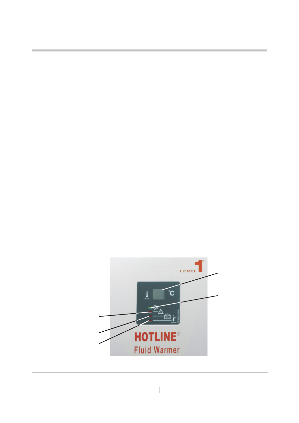
Features
y
SECTION 1 HOTLINE® HL-90
■ Integrated, highly effective design gives unparalleled ease of
use
■ Can be set up and operated in seconds
■ Warmed Intravenous Fluid delivery at up to 4750 ml/hr
■ Digital display of recirculating solution temperature
■ Electronic circuitry continuously monitors recirculating solu-
tion temperature
■ Green “Warming” operating LED
■ Red fault indicator LEDs identify 3 common fault conditions
■ Audible alarm indication
■ Alarm test facility
Fault Condition LEDs
Disposable Interlock
Temperature Displa
Operating LED
Recirculating Solution Level
Over Temperature
HOTLINE® Blood and Fluid Warmer Technical Service Pack
GM-0163-8102-GB-A
Figure 1 - 1: HOTLINE® Front Panel
3
Page 17

Specifications
Dimensions inch cm
Height 9.5 24.1
Length 8.3 21.0
Width 7.0 17.8
Weights lbs kg
Weight (dry) 7.6 3.5
Weight (full) 11.0 5.0
Weight (as Shipped) 7.95 3.6
SECTION 1 Specifications
Electrical HL-90 US HL-90 UK
Supply Voltage 115 V AC 230 V AC
Supply Current 3.0 A 1.5 A
Supply Frequency 50-60 Hz 50-60 Hz
Classification Class 1 Class 1
Safety Rating Type BF applied part Type BF applied part
Power Cord 0.75mm x 3.6 m 0.75mm x 3.6 m
HOTLINE® Blood and Fluid Warmer Technical Service Pack
4
Page 18

Environmental
Temperature
Operating Range 10oC — 45oC,
Transport / Storage -20oC — 70oC
Water Resistance
Enclosure Protection IEC 60529, IP Code: IPX1
Miscellaneous
SECTION 1 Specifications
10 — 95% RH, (non-condensing)
5 — 95% RH, (non-condensing)
Standards Compliance
Fluid Warmers ASTM F2172-02
Product Safety EN60601-1, UL2601-1
EMC EN60601-1-2; FCC 47
Performance
Recirculating Solution temperature display will reach 37oC
from ambient in about 4 minutes.
Operating Temp. Set Point 41.5oC ± 0.5oC
Over Temp. Set Point 42.6oC ± 0.5oC
Max Height on IV pole 107 cm (42 inch)
CFR part 15, Class B
Recirculating Solution 1.4 litres Capacity
HOTLINE® Blood and Fluid Warmer Technical Service Pack
5
Page 19

Contra-indications
■ Not Suitable for use in the presence of flammable anaesthetic
mixtures with air or oxygen or with nitrous oxide.
SECTION 1 Contra-indications
■ HOTLINE
devices generating over 300 mmHg.
®
disposables are not suitable for use with pressure
HOTLINE® Blood and Fluid Warmer Technical Service Pack
6
Page 20
Sub-Assemblies
Blood and
Fluid Warmer
®
Page 21

Sub-assemblies
The principal sub-assemblies to be found in the HOTLINE®
HL-90 are:
■ The enclosure and chassis parts
■ The recirculating solution path components
■ The PCB and its mountings
SECTION 2 Sub-assemblies
These are detailed on the following pages.
HOTLINE® Blood and Fluid Warmer Technical Service Pack
8
Page 22
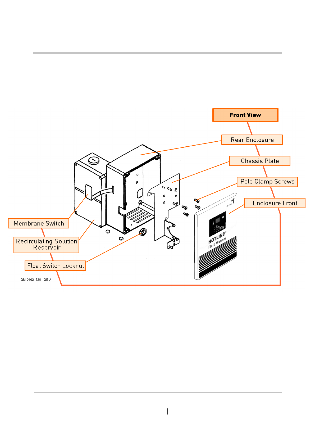
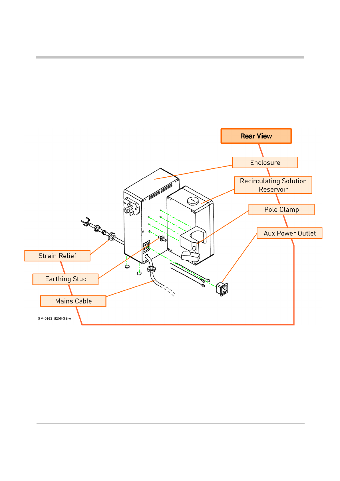
Enclosure (1)
SECTION 2 Enclosure (1)
HOTLINE® Blood and Fluid Warmer Technical Service Pack
9
Page 23
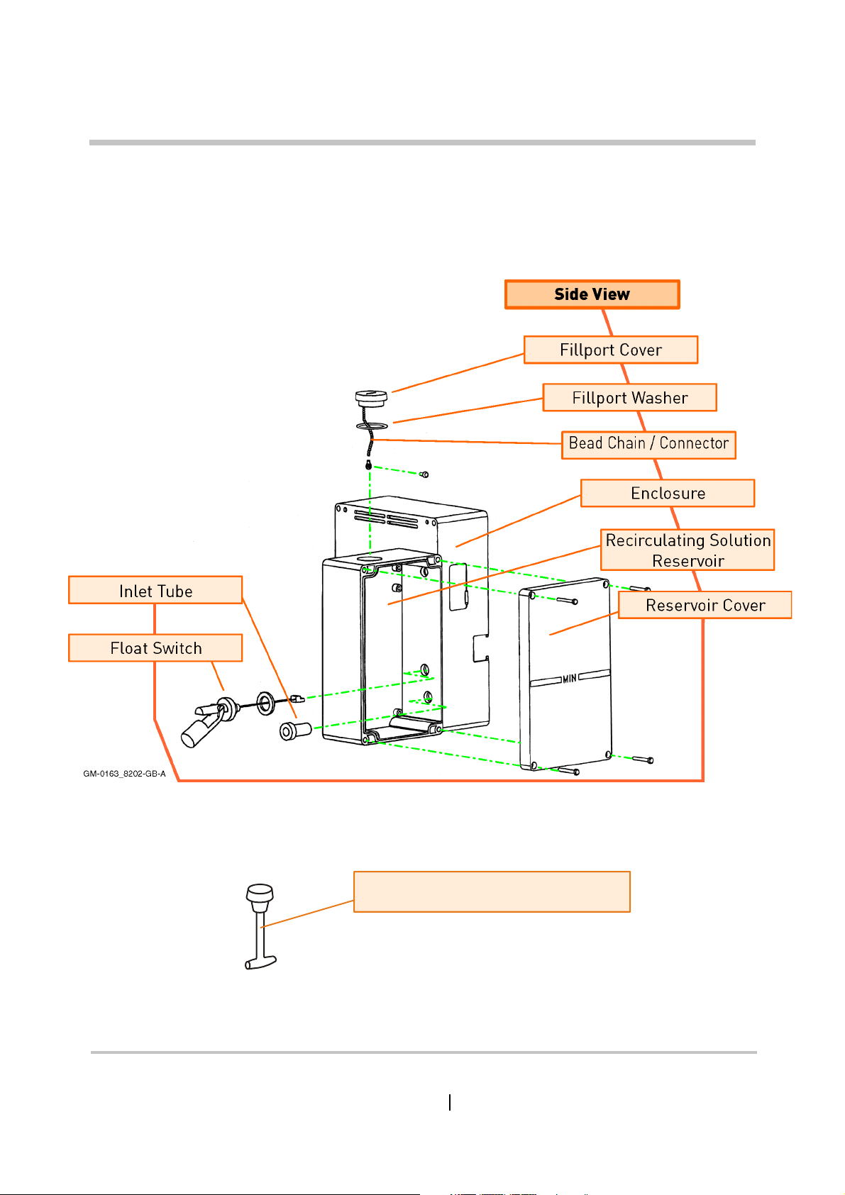
Enclosure (2)
SECTION 2 Enclosure (2)
Newer design Fillport Cover removes
need for chain or retaining screw
HOTLINE® Blood and Fluid Warmer Technical Service Pack
10
Page 24
Enclosure (3)
SECTION 2 Enclosure (3)
HOTLINE® Blood and Fluid Warmer Technical Service Pack
11
Page 25
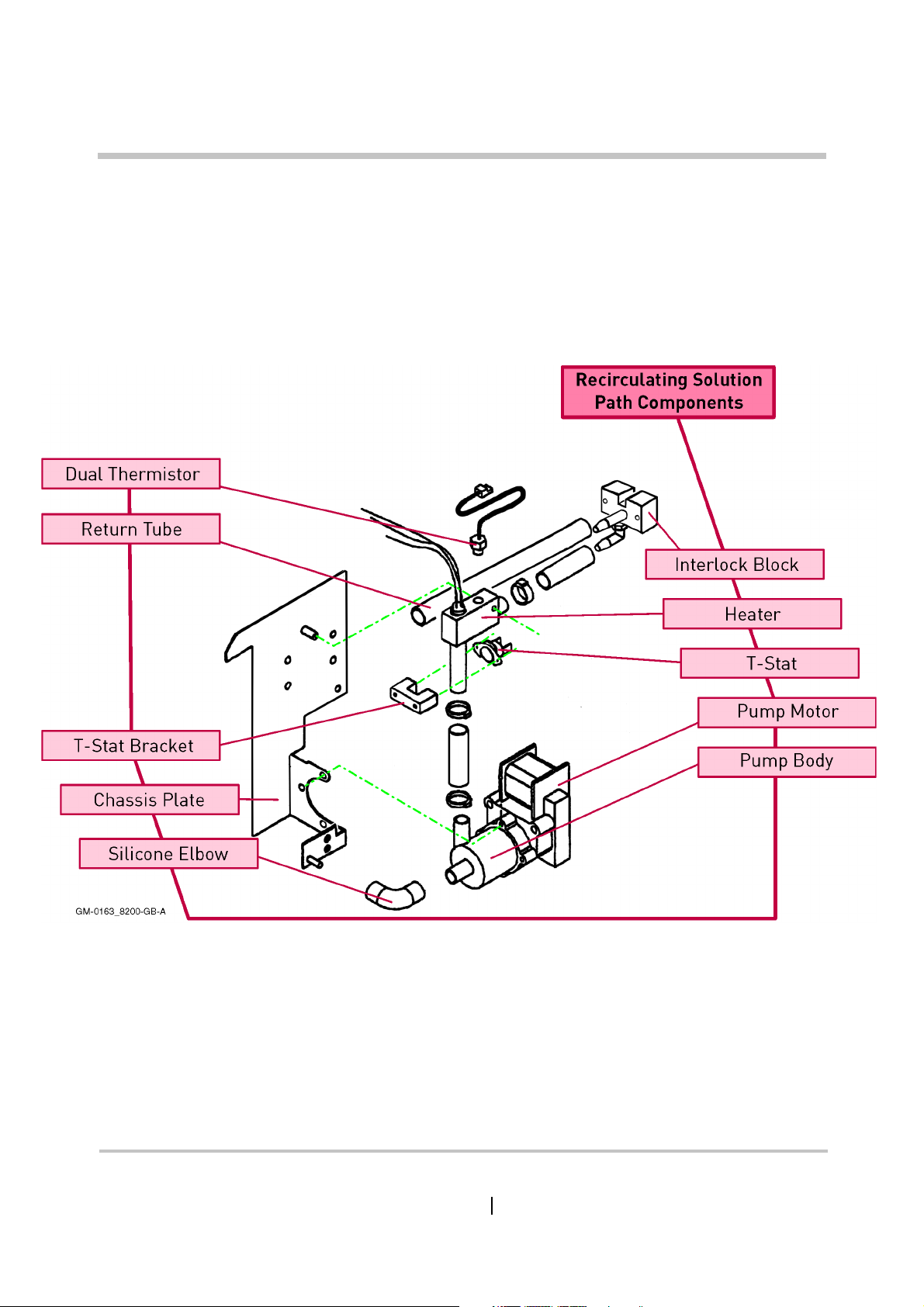
SECTION 2 Recirculating Solution Path
Recirculating Solution Path
HOTLINE® Blood and Fluid Warmer Technical Service Pack
12
Page 26
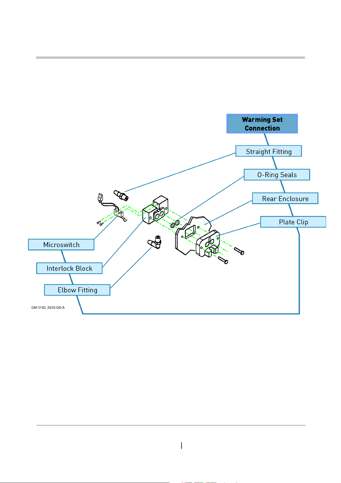
Interlock Block
SECTION 2
Interlock Block
HOTLINE® Blood and Fluid Warmer Technical Service Pack
13
Page 27
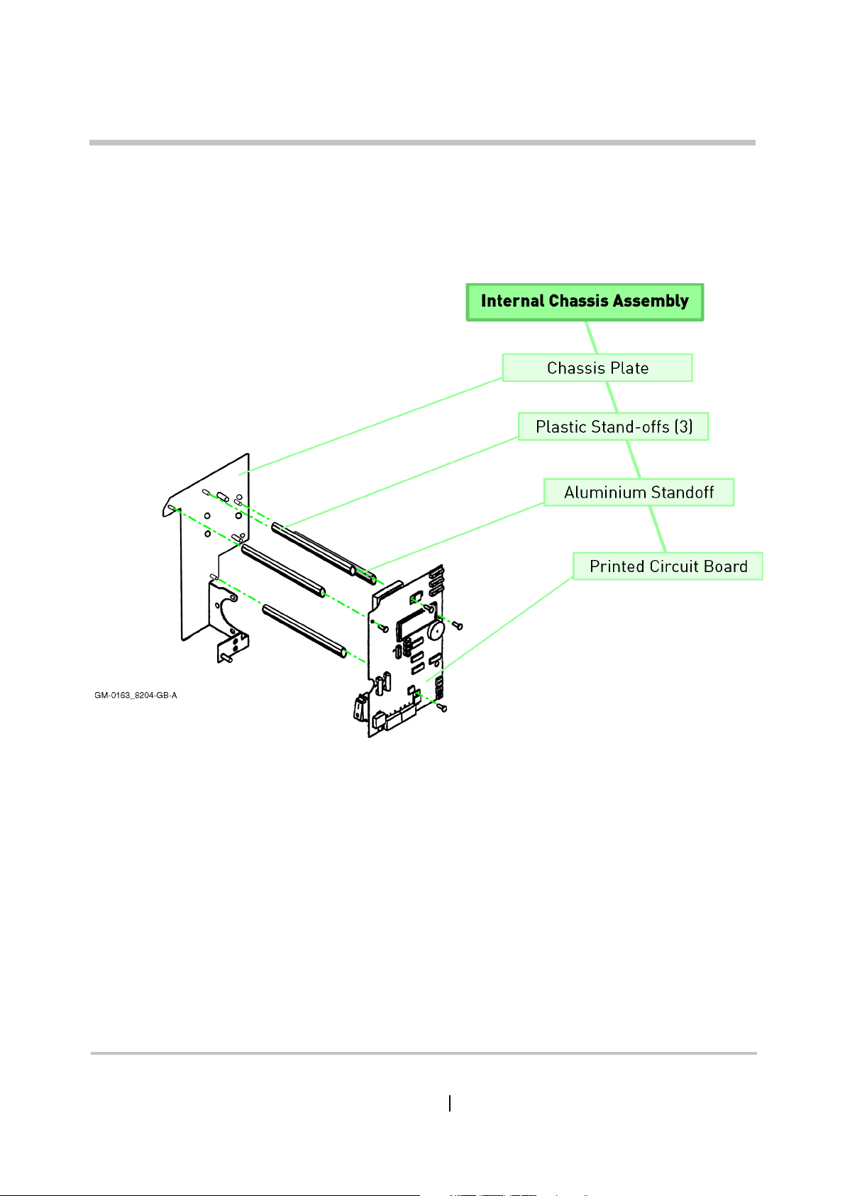
PCB Mounting
SECTION 2 PCB Mounting
HOTLINE® Blood and Fluid Warmer Technical Service Pack
14
Page 28
Technical Description
Blood and
Fluid Warmer
®
Page 29

SECTION 3 Technical Description
Technical Description
General
The HOTLINE® employs a safe recirculating solution heating
system, inherently free of hotspots, to actively warm the HOTLINE
®
Blood and Fluid Warming Set
fluid-filled jacket and sterile IV line. The primary temperature
control circuit limits the recirculating solution to 42oC maximum. In
the unlikely event of a malfunction of this circuit, a second
watchdog circuit will visually and audibly alarm and stop pumping
the recirculating solution if the temperature reaches 43oC.
The heater current is supplied via a thermal cutout, so in the
case of a circulation failure, the heater will be protected against
burn-out; the same cutout will act in the event of catastrophic
breakdown of components in the HOTLINE® circuitry that prevents
the alarm state from disengaging the heater.
These three levels of safety ensure that the IV Fluid in the
HOTLINE® Fluid Warming Set is never exposed to any damaging or
dangerous temperature while the unit is operating.
- a co-axial arrangement of warm
Mechanical
litres of either distilled water or a disinfectant solution. This fluid
will henceforth be referred to as recirculating solution. Do not
confuse recirculating solution with the IV Fluid being dispensed to
the patient.
HOTLINE® Blood and Fluid Warmer Technical Service Pack
The rear left-hand side of the unit is a reservoir, holding 1.4
16
Page 30
SECTION 3 Technical Description
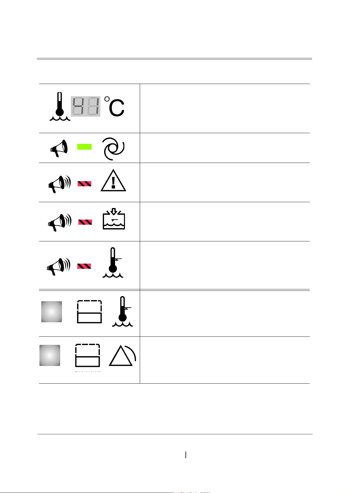
Controls and Indicators
Shows the current temperature of the circulating
warmed recirculating solution.
This steady GREEN indicator illuminates when power is
ON and the Warming Set is correctly installed. The
recirculating solution is being warmed and circulated.
This flashing RED indicator with audible alarm shows
that warming and circulating has been stopped
because the Warming Set is not fitted properly.
Reattach the Warming Set and continue.
This flashing RED indicator with audible alarm shows
that warming and circulating has stopped because
there is not enough recirculating solution in the unit to
operate the float switch. Refill, and continue.
This flashing RED indicator with alarm shows that
warming and circulating has been stopped because the
recirculating solution reached a temperature above the
set point. The unit must be removed from service, and
repairs effected before returning to service.
SIDE PANEL BUTTON
Simulates triggering of the Over Temperature
watchdog alarm for testing.
SIDE PANEL BUTTON
General Alarm Test
Simulates triggering of all alarms for testing.
HOTLINE® Blood and Fluid Warmer Technical Service Pack
17
Page 31

Mechanical (contd)
The outer face of the reservoir is transparent so the
recirculating solution level and flow can both be observed. A float
switch is fitted in the tank, so that the unit cannot operate if there is
insufficient recirculating solution to properly circulate.
Recirculating solution is drawn from the bottom of the reservoir, via
a silicone rubber elbow into a centrifugal pump driven by a 60VA
synchronous electric motor in the main enclosure.
The pump outlet is vertically upwards, and feeds into the
heater assembly via another short length of silicone rubber piping.
The heater asembly is a solid cast L-shaped unit that, in the vertical
leg, incorporates a 300 watt heater element, able to warm the
SECTION 3 Technical Description
recirculating solution from room temperature to 37oC in 4 minutes.
In the horizontal leg of the heater assembly, a special dual
thermistor unit is submerged in the flow, to monitor and control the
warmed recirculating solution temperature.
Clamped to the external surface of the heater assembly is the
T - Stat, a thermally-operated bi-metallic cutout that breaks the
circuit at temperatures above 50oC. The cutout only self-resets
when the temperature has dropped significantly (10oC - 15oC)
below its nominal operating temperature.
The warmed recirculating solution leaving the heater
assembly now enters the interlock block, at the top right-hand side
of the HOTLINE®. This interfaces to the Fluid Warming Set that
contains the sterile line for the patient’s IV fluid. The Fluid Warming
Set needs to be in place so as to operate a microswitch that would
otherwise raise an alarm and cut off the pump. Running back from
the interlock block is the recirculating solution return line, which
leads directly throught the rear of the main enclosure and into the
top of the reservoir.
HOTLINE® Blood and Fluid Warmer Technical Service Pack
18
Page 32

SECTION 3 Technical Description
Electrical Power Circuits
VU
10
C501
10F
U501
R501
453R
µ
GM-HL90_8A103
R502
3.16k
C 2
220F
+
µ
13
U1
1
1
T1
3
4
OPTO
6
CR1
F3 375mA
12
10
9
7
C
C100
100pF
14
R502
3.16k
Figure 3 - 1: HOTLINE® Power Circuits
J6
F1 1.5A
LF1
Filter
J7
6
1
U3
4
2
R4
1k
R3
270R
U2
TRIAC
Gate
F2 1.5A
Contacts
MT2
MT1
SW1
DPST
K1
26
22
TB1
3
4
TB1
5
6
TB1
8
7
38
30
Thermofuse
TB1
56 C
1
2
o
Water
Heater
Input
Pump
Motor
Earth Stud
Line
L
N
E
J10
AUX
Outlet
Power circuitry is conventional, and is constructed on the PCB.
There are three fuses, F1 and F2 (both 1.5A) for the Mains input, and
F3 (375 mA) for the low voltage circuits. F3 is wire-ended device,
soldered into place at the top edge of the PCB.
On the Mains side, the power normally passes through a line
filter to reduce susceptibility to interference (this filter is not always
required for domestic US units.) The pump motor is switched by a
PCB-mounted relay K1, and the heater element is controlled by a
triac. The heater can only be energised when the pump is powered
on, since without recirculating solution flow, the heater element
would quickly overheat.
The heater triac is triggered via an optical isolator, and all the
Mains voltage circuits are physically distanced from the low-voltage
circuits for safety reasons. The low-voltage control circuits are
HOTLINE® Blood and Fluid Warmer Technical Service Pack
19
Page 33

SECTION 3 Technical Description
derived from a conventional step-down transformer. After
rectification and smoothing, the supply is regulated to a nominal 10
volts by U501, an LM317T integrated regulator. Resistors R501 and
R502 set the exact output voltage level.
NOTE: The HOTLINE® is NOT a Class 2 double-insulated device, and
must be connected with a good earth connection to ensure
patient and operator safety.
Control Circuit
R607
178k
O'temp
Test
Alarm
Test
Display
Sensor
-t
-t
Control
Sensor
GM-HL90_8305-A
10
1
R02/4
15k
U3.1
C201
22 F
R207
15.4k
µ
10
VU
CR202
Green
15
CR201
1N4001
R206
3.15k
C
Q1
U1.4
R01/6
78L05
4
14
11
R504
15.4k
6
U1.2
5
15k
7
U3.7
12345678910111213
5
R603
R605
15.4k
15.4k
2
U1.1
3
R602
15.4k
R03/5
5
OT Setp oint
R106
5k
U3.6
15k
R606
11k
11
7
10
R601
11k
R03/3
15k
J1
1
2
3
4
J4
1
2
3
4
13
12
LCD Cal
R102
5k
R01/1
15k
4
AA
LCD Module
J101
R104
1k
R103
105k
11
1
R107
34k
R108
10M
10 10
88
U1.3
99
8
C101
µ
47 F
S
2
U2.1
3
Heat Control
R202
5k
6
R203
154k
R01/7
15k
J201
R01/9
R03/8
15k
R204
1M
9
6
1
15k
R201
16.5k
U2.3
U2.2
5
7
R01/8
15k
7
X
Figure 3 - 2: HOTLINE® Temperature Control Circuits
The control sensor is one of a “siamese twin” pair of
thermistors submerged in the recirculating so luti on flow a s it leav es
the heater. At normal operating temperatures, the thermistors each
have a resistance of about 15k, and this decreases roughly linearly
with increasing temperature.
HOTLINE® Blood and Fluid Warmer Technical Service Pack
20
Page 34

SECTION 3 Technical Description
As a result, the current through the chain [control thermistor -
R202 - R01/9] is roughly proportional to the recirculating solution
temperature, and thus, so is the voltage sample at R202 slider. This
is buffered by U2.1, part of an LP324N quad op-amp, and passed to
U2.2, which is configured as a comparator. At pin 5 of U2.2, a
reference voltage of about 5 volts is created by the voltage divider
resistors R03/8 and R01/8.
If the temperature-dependent sample at pin 6 is less than the
reference level set at pin 5, then pin 7 will go high, which switches
on the darlington driver U3.1, and so turning on the opto/triac/
heater combination. However, this also grounds R207 via CR201,
which starts discharging C201, and so reducing the reference
voltage at U2.2/5. Unless the recirculating solution is very cold, the
reference voltage will soon dip below the sample voltage, so
turning off the heater circuit.
As soon as U3.1 turns off, C201 can start recharging to 5 volts,
and at some point the reference voltage overtakes the sample
voltage, and the heater turns on again, repeating the cycle. R204
provides a modest amout of positive feedback, ensuring that the
switch transitions are snap-action.
You can see that the repetition rate of the circuit depends both
on the RC time constants around C201, and also on the temperature
of the recirculating solution in the reservoir. If this is still some
distance from the desired temperature, the sampled voltage will
“sag” very quickly when the heater turns off, and fresh cold
recirculating solution is pumped through the heater unit.
If, however, the HOTLINE® has been running some while, all the
recirculating solution in the circulation loop will be at, or close to,
the desired temperature, so the sample voltage will hardly move at
all.
HOTLINE® Blood and Fluid Warmer Technical Service Pack
21
Page 35

Digital Display
The temperature control thermistor is one of a pair, siamesed
together in the heater housing. The other of these provides a user
display of the recirculating solution temperature and, as we will see
later, protection in case of failure by the first thermistor.
SECTION 3 Technical Description
R607
178k
O'temp
Test
1
2
3
4
Alarm
Test
Display
Sensor
-t
1
2
3
-t
4
Control
Sensor
GM-HL90_8306-A
R601
11k
R03/3
15k
J1
J4
13
12
LCD Cal
R102
R01/1
15k
78L05
4
14
U1.4
11
5k
R504
15.4k
6
U1.2
4
5
R01/6
15k
7
U3.7
12345678910111213
5
R603
R605
15.4k
15.4k
2
U1.1
3
R602
15.4k
R03/5
5
OT Setpoint
R106
U3.6
15k
5k
R606
11k
11
7
10
AA
LCD Module
J101
R104
1k
R103
105k
11
1
R107
34k
6
R108
10M
10 10
88
U1.3
99
8
C101
47 F
µ
S
Q1
Figure 3 - 3: HOTLINE® Temperature Monitoring Circuits
The output from the display sensor thermistor is buffered by
2
U2.1
3
Heat Control
R202
R203
154k
R01/7
15k
5k
J201
R01/9
15k
10
R03/8
15k
C
15k
U3.1
C201
22 F
R207
15.4k
µ
VU
CR202
Green
15
R206
3.15k
CR201
1N4001
R204
1M
9
1
U2.3
R201
16.5k
10
6
U2.2
5
7
R02/4
1
R01/8
15k
7
X
U1.2, another LP324 quad op-amp device. It passes to U1.1, which is
a summing amplifier, combining the sensed voltage with the
buffered output from U1.4. This allows a degree of offset,
determined by R102, to be introduced for calibration purposes.
The buffered and calibrated voltage is scaled by R103/R104,
and presented to the digital LCD millivolt-meter module for display.
The window in the front case allows two digits to be seen by the
user, although the third digit (tenths of a degree) may be seen by
the technician when the case front is removed.
HOTLINE® Blood and Fluid Warmer Technical Service Pack
22
Page 36

Thermistor Loss
SECTION 3 Technical Description
R607
178k
O'temp
Test
1
2
3
4
Alarm
Test
Display
Sensor
-t
1
2
3
-t
4
Control
Sensor
GM-HL90_8307-A
Q1
U1.4
R01/6
15k
7
78L05
4
14
11
R504
15.4k
6
U1.2
5
U3.7
12345678910111213
5
R603
R605
15.4k
15.4k
2
U1.1
3
R602
15.4k
R03/5
5
OT Setpo int
R106
U3.6
15k
5k
R606
11k
11
7
10
R601
11k
R03/3
15k
J1
J4
13
12
LCD Cal
R102
5k
R01/1
15k
4
LCD Module
J101
R104
1k
R103
105k
11
1
R107
34k
R108
10M
10 10
88
U1.3
99
8
C101
µ
47 F
S
2
3
Heat Control
6
R203
154k
R01/7
R01/7
15k
15k
AA
Figure 3 - 4: HOTLINE® Thermistor Loss Monitoring
U2.1
R202
5k
J201
R01/9
15k
10
R03/8
15k
C
15k
U3.1
C201
22 F
R207
15.4k
µ
VU
CR202
Green
15
R206
3.15k
CR201
1N4001
R204
1M
9
1
U2.3
R201
16.5k
10
6
U2.2
5
7
R02/4
1
R01/8
15k
7
X
Since both control and display thermistors are NTC devices,
their resistance DECREASES with increasing temperature. This
means that if the thermistor or its wiring were damaged somehow,
an open circuit sensor would potentially be a dangerous situation.
The infinitely HIGH resistance of an open circuit would be
interpreted as a very LOW temperature, and so the HOTLINE® would
fail with the heater powered permanently ON.
To prevent this, U2.3 detects that there is a reasonable voltage
being fed to the temperature controller circuit. If the thermistor
circuit ever achieved an effective resistance of some 150K or more,
then U2.3 will turn on sending signal X high. Needless to say, there
is no place on earth cold enough to get this much resistance from
the thermistor through natural causes!
HOTLINE® Blood and Fluid Warmer Technical Service Pack
23
Page 37

SECTION 3 Technical Description
Float
Switch
Interlock
Switch
AA
R03/6
15k
C301
0.1 F
µ
R03/9
R02/3
15k
15k
R01/2
R307
15.4k
15k
J2
1
2
3
J3
1
2
S
X
GM-HL90_8308-A
R302
8.2M
13
U2.4
12
R02/2
15k
Piezo
3
14
U3.3
CR302 Red
15
2
U3.2
CR301 Red
4
13
U3.4
CR303 Red
R03/2
3
14
R301
722R
Float
Interlock
Overtemp
R03/1
15k
15k
Figure 3 - 5: HOTLINE® Thermistor Loss Alarm
R308
15.4k
C302
10 F
12
R304
100k
3
6
U4.2
7
µ
4
U4.1
5
8
14
U4.3
9
10
13
U4.4
11
12
R305
100k
R306
15.4k
10
R03/7
15k
1
2
CR 401
Green
9
5
U3.5
8
R401
1k
12
System
Normal
VU
R 2
270R
Relay
K1
15
Following signal X onto the next page, we see that it reaches
U4.4. U4 is an LP339 - a low-power version of an industry standard
quad comparator with open-collector outputs. Taking signal X high
turns on U4.4’s output, which starves darlington driver U3.5’s input
of current. This was being held on by R03/7, but now it turns off, so
cutting off the relay K1, which in turn removes power from the
pump motor and heater mains circuits, thereby rendering the
HOTLINE® (and any patients it may be attached to) safe.
This arrangement of open-collector devices feeding a
common input effectively creates an OR-gate, allowing multiple
inputs to control the output relay.
HOTLINE® Blood and Fluid Warmer Technical Service Pack
24
Page 38

SECTION 3 Technical Description
Over Temperature Alarm
Earlier, we looked at how the display was generated from the
second thermistor in the siamesed package. There is another good
reason for having a double thermistor arrangement - as safety
watchdog in case of failure.
In this part of the circuit, we take the buffered and calibrated
display signal through R107, and using another quarter of the op-
amp U1, compare it to a pre-selected over temperature set point,
set by R106. If the temperature has got too warm, perhaps because
the primary thermistor has given up, then signal S will be activated.
R607
178k
O'temp
Test
1
2
3
4
Alarm
Test
Display
Sensor
-t
1
2
3
-t
4
Control
Sensor
GM-HL90_8309-A
R601
11k
R03/3
15k
J1
J4
13
12
LCD Cal
R102
R01/1
15k
78L05
4
14
U1.4
11
5k
R504
15.4k
6
U1.2
4
5
R01/6
15k
7
U3.7
12345678910111213
5
R603
R605
15.4k
15.4k
2
U1.1
3
R602
15.4k
R03/5
5
U3.6
15k
OT Setpoint
R106
5k
R606
11k
11
7
10
AA
LCD Module
R104
1k
R103
105k
11
1
R107
34k
R108
10M
10 10
U1.3
99
C101
47 F
µ
Q1
Figure 3 - 6: HOTLINE® Over Temperature Monitoring
10
R03/8
15k
R207
15.4k
µ
VU
CR202
Green
15
R206
3.15k
CR201
1N4001
C
J101
9
2
U2.1
3
1
Heat Control
R202
5k
6
R203
154k
88
R01/7
15k
8
S
J201
R01/9
15k
U2.3
R201
16.5k
R204
1M
10
6
U2.2
5
7
R02/4
15k
U3.1
1
R01/8
15k
7
C201
22 F
X
Since failure of this part of the circuit could be quite
catastrophic, there are two separate methods of verifying that it is
working OK.
HOTLINE® Blood and Fluid Warmer Technical Service Pack
25
Page 39

SECTION 3 Technical Description
Pressing the Alarm Test button artificially lowers the set point
by making U3.6 short out R606. Since the set point is lowered to
below room temperature, this should set off the alarm whatever the
actual fluid temperature.
The second test mechanism is operated by the Over
Temperature Alarm Test button. This overrides the display
thermistor to fake an over temperature situation. You should see
the display rise to an artificially simulated temperature of 43oC -
44oC. Because of the delay (C101 and R107) you need to hold the
button for 2 - 3 seconds to activate the test.
R607
178k
O'temp
Test
1
2
3
4
Alarm
Test
Display
Sensor
-t
1
2
3
-t
4
Control
Sensor
GM-HL90_8314-A
R601
11k
R03/3
15k
J1
J4
13
12
LCD Cal
R102
R01/1
15k
78L05
4
14
U1.4
11
5k
R504
15.4k
6
U1.2
4
5
R01/6
15k
7
U3.7
12345678910111213
5
R603
R605
15.4k
15.4k
2
U1.1
3
R602
15.4k
R03/5
5
U3.6
15k
OT Setp oint
R106
5k
R606
11k
11
7
10
AA
LCD Module
J101
R104
1k
9
R103
105k
11
1
R107
34k
R108
10M
10 10
88
U1.3
99
8
C101
µ
47 F
S
2
U2.1
1
3
Heat Control
R202
5k
6
R203
154k
J201
R01/9
15k
U2.3
R201
16.5k
R01/7
15k
Q1
Figure 3 - 7: HOTLINE® Over Temperature Alarm Test
Signal S operates in much the same way as signal X did
R03/8
15k
6
5
R204
U2.2
7
1M
R01/8
X
10
C
R206
3.15k
VU
10
CR202
Green
7
R02/4
15k
15
U3.1
1
R207
CR201
15.4k
C201
22 F
1N4001
µ
15k
previously, using U4.3 to cut off the pump and heater circuits. In
addition however, there is a LED, driven by U3.4, visible from the
case exterior to warn the operator that this fault situation has
occurred.
HOTLINE® Blood and Fluid Warmer Technical Service Pack
26
Page 40

SECTION 3 Technical Description
Interlock
Flasher
R03/6
15k
C301
0.1 F
R03/9
R02/3
15k
15k
R01/2
R307
15.4k
15k
Float
Switch
Switch
AA
J2
1
2
3
J3
1
2
S
X
GM-HL90_8310-A
Figure 3 - 8: HOTLINE
R302
8.2M
µ
13
U2.4
12
R02/2
15k
Piezo
14
3
U3.3
CR302 Red
15
2
U3.2
CR301 Red
4
13
U3.4
CR303 Red
®
Over Temperature Alarm
R03/2
3
15k
14
R301
722R
Float
Interlock
Overtemp
R03/1
15k
R308
15.4k
C302
10 F
12
R304
100k
3
6
U4.2
7
µ
4
U4.1
5
8
14
U4.3
9
10
13
U4.4
11
12
R305
100k
R306
15.4k
10
R03/7
15k
1
2
CR 401
Green
9
5
U3.5
8
R401
System
Normal
1k
12
VU
R 2
270R
Relay
K1
15
Float
Switch
Interlock
Switch
AA
R03/6
15k
C301
µ
0.1 F
R03/9
R02/3
15k
15k
R01/2
R307
15.4k
15k
J2
1
2
3
J3
1
2
S
X
GM-HL90_8311-A
R302
8.2M
13
U2.4
12
R02/2
15k
Piezo
3
14
U3.3
CR302 Red
15
2
U3.2
CR301 Red
4
13
U3.4
CR303 Red
R03/2
3
14
R301
722R
Float
Interlock
Overtemp
Figure 3 - 9: HOTLINE® Alarm Flasher
12
R03/1
15k
15k
R308
15.4k
C302
10 F
R304
100k
3
6
U4.2
7
µ
4
U4.1
5
8
14
U4.3
9
10
13
U4.4
11
12
R305
100k
R306
15.4k
10
R03/7
15k
1
2
CR 401
Green
9
5
U3.5
8
System
Normal
R401
1k
12
VU
R 2
270R
Relay
K1
15
HOTLINE® Blood and Fluid Warmer Technical Service Pack
27
Page 41

SECTION 3 Technical Description
The alarm LED does not return directly to the positive rail, as
you might expect. Instead it gets its power from U2.4, which is
configured as a low-frequency square-wave oscillator. This means
that the LED can only light up when U2.4’s output is high - so it
flashes on and off to attract attention.
Whenever the LED is ON the piezo-sounder is powered by the
volt-drop across the LED’s current-limiting resistor R301, so it beeps
in synchronism with the flashing of the alarm LED.
Exercise: If more than one alarm happened at once, then two or
more LEDs would be flashed by this circuit. The extra current drain
should increase the volt-drop across R301, so you would expect the
Piezo-sounder to increase in power and volume for every extra alarm
condition.
QUESTION...
Guess how much percentage increase in beep volume results
from ALL alarms simultaneously, compared to a single alarm?
Now try to justify your answer!
HOTLINE® Blood and Fluid Warmer Technical Service Pack
28
Page 42

Interlock Alarm
SECTION 3 Technical Description
Float
Switch
Interlock
Switch
AA
12
R03/6
15k
C301
0.1 F
µ
R03/9
R02/3
15k
15k
R01/2
R307
15.4k
15k
J2
1
2
3
J3
1
2
S
X
GM-HL90_8312-A
R302
8.2M
13
U2.4
12
R02/2
15k
Piezo
3
14
U3.3
CR302 Red
15
2
U3.2
CR301 Red
4
13
U3.4
CR303 Red
R03/2
3
14
R301
722R
Float
Interlock
Overtemp
R03/1
15k
15k
R308
15.4k
C302
10 F
R304
100k
3
6
U4.2
7
µ
4
U4.1
5
8
14
U4.3
9
10
13
U4.4
11
12
R305
100k
R306
15.4k
10
R03/7
15k
1
2
CR 401
Green
9
5
U3.5
8
System
R401
1k
12
Normal
VU
R 2
270R
Relay
K1
15
Figure 3 - 10: HOTLINE® Warming Set Interlock Alarm
The interlock switch is a simple microswitch which is operated
by the insertion of the warming set into the twin socket. If you were
to switch the pump on with no warming set connected, the results
would not be catastrophic, nor particularly dangerous, but they
could be awfully messy!
Therefore, if the Interlock Switch is not made, the pump (and
heater) will not run. The flashing LED lets you know why the
HOTLINE® is refusing to co-operate.
This part of the circuit has a fail-safe action that might mislead
you if you’re faultfinding. U03.2 is kept turned on by the pull-up
resistor R03/1 so that if there is a fault in the interlock switch
off-board wiring, or the J2 connector isn’t fully connected, the alarm
is defaulted ON. You need a good continuous circuit through J2 to
allow U3.7 to pull U03.2 low and turn the alarm state off.
HOTLINE® Blood and Fluid Warmer Technical Service Pack
29
Page 43

SECTION 3 Technical Description
U3.7 is the Alarm Test circuit; if there is a fault in the alarm test
switch, nothing happens except the unit will be unable to test its
alarms. The integrity of the alarm itself would not be compromised
by alarm test switch failure.
Recirculating Solution Level Alarm
12
Float
Switch
Interlock
Switch
AA
S
X
J2
1
2
3
J3
1
2
R03/9
15k
R01/2
R307
15.4k
GM-HL90_8313-A
R03/6
15k
R02/3
15k
C301
0.1 F
15k
R302
8.2M
µ
13
U2.4
12
R02/2
15k
Piezo
3
14
U3.3
CR302 Red
15
2
U3.2
CR301 Red
13
4
U3.4
CR303 Red
R03/2
3
15k
14
R301
722R
Float
Interlock
Overtemp
R03/1
15k
R308
15.4k
C302
10 F
R304
100k
3
6
U4.2
7
1
µ
4
2
U4.1
5
8
14
U4.3
9
10
13
U4.4
11
12
R305
100k
R306
15.4k
Figure 3 - 11: HOTLINE® Low recirculating solution Level Alarm
R03/7
15k
5
U3.5
10
CR 401
Green
9
8
R401
1k
12
System
Normal
VU
R 2
270R
Relay
K1
15
The recirculating solution level alarm is an almost exact copy
of the interlock alarm arrangements. The starting point for this,
however, is a float switch mounted in the reservoir. The one
significant difference is that the interlock switch acts
instantaneously, whereas the float switch has a time delay element
(R308 and C302) to reduce false alarms due to recirculating solution
just sloshing about.
Both interlock and recirculating solution level alarms will
be exercised by signal AA, which is derived from the general
Alarm Test button (left) mentioned earlier.
HOTLINE® Blood and Fluid Warmer Technical Service Pack
30
Page 44

SECTION 3 Technical Description
Answer to the page 28 Puzzler
As you probably guessed, it’s a bit of a trick question. The fact
is that it really does look like the volume should increase, but this is
apparently not the case. So what’s going on here?
Well, we kind of helped you to think that the current in R301
must increase with every extra LED, but this isn’t necessarily so. All
this current has to come from the Op-amp U2.4, type number
LP324N, which is described by its makers as a MICROPOWER device.
For this reason, its ability to source current is less than you
might have thought. You can see that from this graph:
Not wanting to bore you, we won’t figure out all the voltdrops
across all the various components, but you can see that if the first
LED is taking 12 - 15 mA (a reasonable amount), then the Op-amp is
already pretty much in saturation, and there is no more current
available, no matter how many LEDs you light up.
So maybe the question should have been, did the first LED get
any dimmer as the second and third got added?
HOTLINE® Blood and Fluid Warmer Technical Service Pack
31
Page 45

Disassembly Procedures
Blood and
Fluid Warmer
®
Page 46

Tools you will need
■ Needle-nose pliers
■ Philips head screwdriver
■ Small straight head screwdriver
1
■
■
■
/8 inch A/F Allen key (hex wrench)
7
/8 inch A/F open ended spanner (wrench)
3
/4 inch A/F open ended spanner (wrench)
SECTION 4 Tools you will need
7
■
■
■
/16 inch A/F open ended spanner (wrench)
3
/8 inch A/F deep box spanner OR socket and extension drive
1
/4 inch A/F open ended spanner (wrench)
■ 10 mm A/F open ended spanner (wrench)
Optional
Oetiker Clenching Tool
■
(This will be needed if it is intended to replace the heater ele-
ment or the pump/motor combination)
HOTLINE® Blood and Fluid Warmer Technical Service Pack
33
Page 47

Disassembly
Step 1: Open the case
SECTION 4 Disassembly
WARNING: Ensure that the HOTLINE® is disconnected from the Mains power.
If the HOTLINE
interior components may be hot.
Place the HOTLINE® on a firm surface at a convenient height.
Loosen the front cover screws. Early models have six screws, facing
forward. These screws are tethered to the front panel, so it is neither
necessary or desirable to completely remove them.
®
has been recently used, be aware that some
Figure 4 - 1: The underneath view of a HOTLINE® with the newer (one-part) case.
HOTLINE® Blood and Fluid Warmer Technical Service Pack
34
Page 48

SECTION 4 Disassembly
Later models have only two front cover retaining screws, locat-
ed under the unit. Again, it is not necessary to completely remove
these screws.
Figure 4 - 2: Loosen, but don’t completely remove these screws
WARNING: STATIC-SENSITIVE COMPONENTS.
!
HOTLINE® Blood and Fluid Warmer Technical Service Pack
Ensure that proper antistatic precautions are taken before
attempting any procedure that requires handling the PCB.
35
Page 49

Step 2: Remove the PCB
Remove connectors J2, J3, J4 by gently pulling on them.
SECTION 4 Disassembly
Figure 4 - 3: Disconnecting J3
Do not pull on the wiring, but grasp the connector body itself.
It may be easier to use the needle-nose pliers.
HOTLINE® Blood and Fluid Warmer Technical Service Pack
36
Page 50

SECTION 4 Disassembly
Remove the membrane switch ribbon connection from J1 by
gently pulling it.
Figure 4 - 4: Membrane Switch Connector
Now release the mains input cable from the “Lego brick” termi-
nals at the bottom front of the case.
Figure 4 - 5: Mains Cable Input Terminals
HOTLINE® Blood and Fluid Warmer Technical Service Pack
37
Page 51

SECTION 4 Disassembly
Remove the eight wires from the terminals along the bottom
edge of the PCB. To release the wires, each terminal’s orange tab
must be pressed into the terminal body with pliers.
Figure 4 - 6: Opening the terminal by squeezing the orange release tab
HOTLINE® Blood and Fluid Warmer Technical Service Pack
38
Page 52

SECTION 4 Disassembly
Alternatively, the tabs may be manipulated with a small
straight screwdriver through the slot on the terminal’s top surface.
Remove the four screws indicated.
GM-0163_8408-GB-A
Figure 4 - 7: PCB Mounting Points
1
(Only on older models)
2
4
3
Figure 4 - 8: Older versions have an additional fixing screw, making five in all.
HOTLINE® Blood and Fluid Warmer Technical Service Pack
39
Page 53

SECTION 4 Disassembly
Step 3: Release the Earth Stud
With the PCB removed, you will be able to see the external
Earthing Stud which is attached to the chassis and passes out
through the rear of the case. Undo the 10mm nut holding it in place,
using a spanner on the outside to prevent rotation. Undo the 3/8
inch nut and take off the earth conductors from the internal Earth-
ing Star Point.
Internal
Earthing
Star Point
External
Earthing Stud
Figure 4 - 9: Earthing Arrangements
Notice the order of assembly on this terminal: the crinkle
washers are not there just to prevent unscheduled vibrational dis-
assembly, but also to cut into any corrosion on the ring termina-
tions and ensure good continuity.
GM-0163_8415-GB-A
Figure 4 - 10: Use of Crinkle Washers
HOTLINE® Blood and Fluid Warmer Technical Service Pack
40
Page 54

SECTION 4 Disassembly
Step 4: The Recirculating Solution Return Pipe
The recirculating solution return pipe emerges straight from
the back of the interlock block and crosses the enclosure to the left-
hand side, where it passes into the reservoir.
GM-0163_8410-GB-A
Figure 4 - 11: The Return Pipe
Release it from the interlock block by gentle persuasion. No
tools should be needed.
HOTLINE® Blood and Fluid Warmer Technical Service Pack
41
Page 55

SECTION 4 Disassembly
Step 5: Removing the Chassis
Undo the four
GM-0163_8411-GB-A
poleclamp retaining
screws from the rear
of the chassis. Be
ready to catch the
poleclamp if it
should fall off the
back of the case.
Normally the
silicone sealant will
prevent this.
Figure 4 - 12: The Pole Clamp Retaining Screws also hold the Chassis in place
Figure 4 - 13: Older Pumps have a rigid moulded plastic elbow here
HOTLINE® Blood and Fluid Warmer Technical Service Pack
Gently
pull on the sil-
icone rubber
elbow pump
inlet pipe to
release it from
the spout
leading from
the reservoir.
42
Page 56

SECTION 4 Disassembly
Slide the chassis forward at the left-hand side until you can re-
lease the final silicone tube from the elbow beneath the interlock
block. Once that tube is freed, the entire chassis can be taken out.
Figure 4 - 14: Dissection Complete!
HOTLINE® Blood and Fluid Warmer Technical Service Pack
43
Page 57

Reassembly
Reassembly is a straightforward process, consisting of
following the aforementioned procedures in the reverse order.
Measurements
While you have the chance on a (presumed) good HOTLINE®,
make a note of the following resistance measurements. They may
be useful when fault finding in future.
SECTION 4 Reassembly
■ Pump Motor Coil (Specify March or GRI)
■ Heater Element
■ Transformer Primary
■ Relay K1 Coil
■ Display Thermistor
■ Display Thermistor
■ Control Thermistor
■ Control Thermistor
(J4:1-2) (ambient temp)
(J4:1-2) (operating temp)
(J4: 3-4) (ambient temp)
(J4: 3-4) (operating temp)
HOTLINE® Blood and Fluid Warmer Technical Service Pack
44
Page 58

Maintenance, Testing
and Calibration
Blood and
Fluid Warmer
®
Page 59

Maintenance
Before each use
Carefully inspect the HOTLINE® for signs of damage, cracked or
split case, insecure poleclamp, damaged mains cable, etc.
If the Disposable Set does not install easily, lubricate the O-
Ring Seals.
Lubricating the O-Ring Seals
Using a cotton swab, apply a small amount of silicone grease
(Smiths Medical Part Number EZL 80-04-002) to the O-Rings in the
SECTION 5 Maintenance
Disposable Set connector block.
If this does not solve the problem, reject the unit.
After each use
Wipe all external surfaces of the HOTLINE® with a soft cloth,
using an aqueous solution of mild detergent. If necessary, the
external surfaces may be disinfected using a solution of 10% bleach
in distilled water.
■ Do not autoclave.
■ Do not use alcohol or solvents.
■ Do not use abrasive cleaning agents.
■ Do not use cold sterilants.
■ Do not immerse any part of the HOTLINE
HOTLINE® Blood and Fluid Warmer Technical Service Pack
®
in liquids.
46
Page 60

Routine Maintenance Tasks
Smiths Medical recommends that preventative maintenance
be carried out at specified intervals. Some maintenance tasks need
to be repeated at 30-day intervals and others at annual intervals,
depending on your choice of recirculating solution.
The three approved recirculating solutions and their
associated maintenance protocols are:
SECTION 5 Maintenance
Recirculating
Solution
Sterile
Distilled
Water
Isopropyl
Alcohol
Solution
Hydrogen
Peroxide
Solution
At 30-day Intervals At 12-month Intervals
Visual Inspection
Lubricate O-Ring Seals
Replace Recirculating
Solution
Visual Inspection
Lubricate O-Ring Seals
Replace Recirculating
Solution
Visual Inspection
Lubricate O-Ring Seals
Replace Recirculating Solution
Verify Temperature Calibration
Replace Recirculating Solution
Verify Temperature Calibration
Replace Recirculating Solution
Verify Temperature Calibration
Test All Alarms
Replace O-Ring Seals
Electrical Safety Test
Test All Alarms
Replace O-Ring Seals
Electrical Safety Test
Test All Alarms
Replace O-Ring Seals
Electrical Safety Test
Precise directions for mixing the above solutions to the correct
strength are given on page 54.
Exceptionally, if the unit has had any non-routine servicing or
repair work, it will need to undergo a more thorough test and
recalibration sequence. This is detailed on page 64 and onwards.
HOTLINE® Blood and Fluid Warmer Technical Service Pack
47
Page 61

Every 30 days
■ Perform a Visual Inspection looking for damage to the case,
poleclamp, mains cable, etc.
■ Lubricate O-Ring Seals with a cotton swab, applying a small
amount of silicone grease to the O-Rings.
Either, if using DISTILLED WATER as the
recirculating solution:
■ Drain and replace the recirculating solution as described on
SECTION 5 Every 30 days
page 54.
or, if using ISOPROPYL ALCOHOL as the
recirculating solution:
■ Drain and replace the recirculating solution as described on
page 56.
Finally
■ Fill in, sign, and date the maintenance log record!
HOTLINE® Blood and Fluid Warmer Technical Service Pack
48
Page 62

Every 12 Months
Alarm Testing
Place the HOTLINE® on a suitable firm surface. Visually check
that the recirculating solution level in the reservoir is above the MIN
mark. Attach a Disposable Set, ensuring that it is free from kinks and
twists.
Plug the unit into the electricity supply and switch on. Verify
that the unit is working normally (recirculating solution circulating,
temperature display gradually rising towards 41°C).
SECTION 5 Every 12 Months
General Alarm Test
Press the General Alarm Test button. Observe:
■ the GREEN LED extinguishes.
■ the THREE RED LEDs light up.
■ the AUDIBLE ALARM commences beeping.
■ the RECIRCULATING SOLUTION ceases circulating.
If any of the above responses are missing, the unit must be
removed from service and repaired.
HOTLINE® Blood and Fluid Warmer Technical Service Pack
49
Page 63

SECTION 5 Every 12 Months
Over Temperature Alarm Test
Allow the unit to run for sufficient time to stabilise the
temperature. Press and hold the Over Temperature Alarm Test
button. Observe:
■ the DISPLAY rises to 43°C - 44°C .
■ the GREEN LED extinguishes.
■ the RED Over Temperature LED lights up.
■ the AUDIBLE ALARM commences beeping.
■ the RECIRCULATING SOLUTION ceases circulating.
If any of the above responses are missing, the unit must be
removed from service and repaired.
Recirculating Solution Level Alarm
Remove the Fill Port plug. Using a non-magnetic tool, gently
depress the float switch arm.
Figure 5 - 1: Depressing the float
switch. Here you see an offcut of
scrap Disposable Set performing
excellently as a non-magnetic probe.
HOTLINE® Blood and Fluid Warmer Technical Service Pack
50
Page 64

SECTION 5 Every 12 Months
Observe that:
■ the GREEN LED extinguishes.
■ the RED recirculating Solution Level LED lights up.
■ the AUDIBLE ALARM commences beeping.
■ the RECIRCULATING SOLUTION ceases circulating.
If any of the above responses are missing, the unit must be
removed from service and repaired. The unit should return to
normal operation upon releasing the float switch.
Disposable Set Interlock Alarm
While the unit is working normally, gently ease the Disposable
Set away from the interlock block. Be aware that a small amount of
recirculating solution may escape during this test. Before the
Disposable Set is fully disconnected, the alarm should operate.
Observe that:
■ the GREEN LED extinguishes.
■ the RED Interlock Alarm LED lights up.
■ the AUDIBLE ALARM commences beeping.
■ the recirculating SOLUTION ceases circulating.
If any of the above responses are missing, the unit must be
removed from service and repaired. The unit should return to
normal operation upon correctly reattaching the Disposable Set.
HOTLINE® Blood and Fluid Warmer Technical Service Pack
51
Page 65

Replace O-Ring Seals
GM-0163_8501-GB-A
Figure 5 - 2: Getting access to the O-Ring Seals
SECTION 5 Every 12 Months
■ Remove the socket head screws with an
1
/
-inch Allen key.
8
■ Remove the disposable interface block, being careful of the
microswitch lever.
■ Using a cotton swab, remove the old O-Rings, and clean out
the empty sockets.
Figure 5 - 3: Revealed: the O-Rings in their niches
HOTLINE® Blood and Fluid Warmer Technical Service Pack
52
Page 66

SECTION 5 Every 12 Months
■ Apply a smear of silicone grease (Smiths Medical Part
Number EZL 80-04-002) to two new O-Rings, and locate
them in the sockets.
■ Re-attach the disposable interface block.
■ Re-fit the socket head screws. Again, take care not to
damage or bend the microswitch operating lever.
A kit of parts is available to make this task simpler. Please ask for
part number reference EZL 80-04-001.
Either, if using DISTILLED WATER as the
recirculating solution:
■ Drain and replace the recirculating solution as described on
page 54.
or, if using ISOPROPYL ALCOHOL as the
recirculating solution:
■ Drain and replace the recirculating solution as described on
page 56.
or, if using HYDROGEN PEROXIDE as the
recirculating solution:
■ Drain and replace the recirculating solution as described on
page 57.
Finally
■ Fill in, sign, and date the maintenance log record!
HOTLINE® Blood and Fluid Warmer Technical Service Pack
53
Page 67

SECTION 5 Maintenance Solutions
Maintenance Solutions
At service intervals of either 12-months or 30-days, depending on the
composition of your recirculating solution, you will need supplies of ready mixed
solutions to perform maintenance. To make up a batch (1.4 litres) of solution, you
will need:
Formula 1
140ml of 3% Hydrogen Peroxide PLUS 1260ml distilled water
This may be used as a disinfectant fluid for flushing the recirculating solution
path during routine maintenance, or as a long-life recirculating solution enabling
fluid change intervals to be extended to 12-monthly.
Formula 2
700ml of 70% Isopropyl Alcohol PLUS 700ml distilled water
This may be used as a disinfectant fluid for flushing the recirculating
solution path during routine maintenance, or as a recirculating solution. It is NOT
suitable for long-term use, and must be replaced at 30-day intervals.
Changing Recirculating Solution (Distilled Water)
If using plain distilled water as the recirculating fluid, then this
must be changed at the 30-day service interval, using the procedure
given here. Smiths Medical currently recommends using the
Hydrogen Peroxide based recirculating solution which allows a
12-monthly recirculating solution change protocol, resulting in a
significant reduction of service time.
HOTLINE® Blood and Fluid Warmer Technical Service Pack
54
Page 68

SECTION 5 Maintenance Solutions
■ Unplug the HOTLINE®.
■ (Old case) Remove the Fill Port plug and hold the Unit over a
sink to empty the water.
(New case) Deploy the drain tube to empty the Unit.
Interlock Block
disposable connector
Pole Clamp
GM-HL90-8508-en
Drain Tube End Cap
Fill Port
Stowage Clip
(for drain tube when
not deployed)
Drain Tube
(in deployed posn)
Figure 5 - 4: Rear view of new-style HOTLINE case, showing drain tube
■ Rinse reservoir with distilled water twice.
■ Refill the reservoir with 1.4 litres of disinfectant flushing
solution made to one of the formulae shown in the blue
panel above. Do not fill the HOTLINE® reservoir with a
Disposable Set in place, as this may result in an airlock in the
HOTLINE® warmer.
■ Connect a Disposable Set to the HOTLINE®.
■ Plug the Unit in and switch on.
■ Allow the disinfectant solution to circulate for 30 minutes.
HOTLINE® Blood and Fluid Warmer Technical Service Pack
55
Page 69

SECTION 5 Maintenance Solutions
■ Switch off and disconnect the Unit.
■ Empty the unit once more.
■ Rinse reservoir with distilled water again.
■ Refill the unit with 1.4 litres of sterile distilled water.
■ Replace the Fill Port plug.
NOTE: Unless using one of the approved maintenance solutions, use only
sterile distilled or de-ionised water. Failure to do so may lead to a
build-up of mineral deposits in the recirculating solution path which
may impair heater performance.
Changing Recirculating Solution (Isopropyl Alcohol)
Since the Isopropyl Alcohol solution gradually loses potency,
it must be replaced at the 30-day service interval using the
following procedure:
■ Prepare two batches of 1.4 litres of recirculating solution
according to formula 2 above for 35% Isopropyl Alcohol
maintenance solution.
■ Drain the HOTLINE®, and refill with one of the prepared
batches.
■ Install an L-70 or L-70 NI Disposable Administration Set in
the HOTLINE®’s Disposable Set connector.
■ Turn on the HOTLINE® and allow the fresh fluid to circulate
for 30 minutes.
HOTLINE® Blood and Fluid Warmer Technical Service Pack
56
Page 70

SECTION 5 Maintenance Solutions
■ Switch off the HOTLINE® and dispose of the Disposable Set
in accordance with the usual procedures for your
establishment. Drain the Fluid from the HOTLINE® and
discard.
■ Refill the HOTLINE® with the second of the Isopropyl Alcohol
solution batches you made earlier.
NOTE: If the HOTLINE® requires topping up at any time before the next
routine recirculating solution change, make sure you always use the
correct mix of Isopropyl Alcohol and Distilled water.
Changing Recirculating Solution (Hydrogen Peroxide)
At the annual routine service interval the Hydrogen Peroxide
solution must be replaced as follows:
■ Prepare two batches of 1.4 litres of recirculating solution
according to formula 1 above for 0.3% Hydrogen Peroxide
maintenance solution.
■ Drain the HOTLINE®, and refill with one of the prepared
batches.
■ Install an L-70 or L-70 NI Disposable Administration Set in
the HOTLINE®’s Disposable Set connector.
■ Turn on the HOTLINE® and allow the fresh fluid to circulate
for 30 minutes.
■ Switch off the HOTLINE® and dispose of the Disposable Set
in accordance with the usual procedures for your
HOTLINE® Blood and Fluid Warmer Technical Service Pack
57
Page 71

SECTION 5 Maintenance Solutions
establishment. Drain the fluid from the HOTLINE® and
discard.
■ Refill the HOTLINE® with the second of the recirculating
solution batches you made earlier.
NOTE: If the HOTLINE® requires topping up at any time before the next
routine recirculating solution change, make sure you always use the
correct mix of Hydrogen Peroxide and Distilled water.
Temperature Checking
TEMP
GM-HL90-8502
Figure 5 - 5: A HOTLINE® HLTA-40 TEMP CHECK wet thermometer
CHECK
To accurately verify the displayed recirculating solution
temperature, you will need a HOTLINE® HLTA-40 TEMP CHECK
thermometer. This bespoke unit is inserted into the recirculating
solution flow and reads the temperature directly from the
recirculating solution as it leaves the heater element and internal
thermistor sensors. This is the point at which the recirculating
solution is at its highest temperature.
Measuring the temperature in the recirculating solution
reservoir is less accurate. Typically the temperature here may be
several degrees cooler, dependent on ambient temperature and
other factors.
HOTLINE® Blood and Fluid Warmer Technical Service Pack
58
Page 72

SECTION 5 Maintenance Solutions
If you do not have a HOTLINE® TEMP CHECK thermometer,
units may be returned to Smiths Medical for temperature
verification.
Set up the HOTLINE® ready for use as before. Attach the TEMP
CHECK thermometer to the interlock block of the HOTLINE® and
connect the Disposable Set to the TEMP CHECK.
Carefully unpeel the black sticker from the back of the
HOTLINE®, and loosely attach it in a safe place ready for re-use. Plug
the TEMP CHECK ’s Mains cable into the Auxiliary Outlet socket of
the HOTLINE®.
NOTE: The Auxiliary Outlet is for use only with approved accessories
supplied by your Smiths Medical distributor for that purpose.
Run the HOTLINE® for 15 minutes to allow the temperature to
stabilise. Verify that:
■ the TEMP CHECK indicates a recirculating solution tempera-
ture between 41°C and 42°C
■ The HOTLINE®’s display indicates the same temperature.
If either of these conditions is not met, the unit will require
either recalibration or repairing and recalibration before it can be
returned to active service.
If both conditions are satisfied, dismantle the test assembly,
and replace the black sticker over the Aux socket. Document the
date and results of your tests and return the HOTLINE® to active
service.
HOTLINE® Blood and Fluid Warmer Technical Service Pack
59
Page 73

SECTION 5 Routine Maintenance Checklists
Routine Maintenance Checklists
You may freely photocopy the checklists on the next three
pages to act as a continuing record of your routine HOTLINE® HL-90
maintenance.
The correct checklist to use is dependent on the choice of
protocol used for maintenance on the HOTLINE®s in your care. If
you choose to stick to the traditional distilled water recirculating
solution, you will need the first checklist. This allows for the
changing of the recirculating solution on a monthly cycle.
Otherwise, the third checklist corresponds with Smiths
Medical’s recommended protocol of having a 12-month interval
between solution changes, and using a disinfectant mixture as the
recirculating solution on a permanent basis.
In some territories, Hydrogen Peroxide may not be readily
available, or it may be that it is not included in the establishment’s
preferred protocols. If that is the case, and it is still necessary to
maintain a disinfectant recirculating solution, then the second
checklist gives the correct pattern when using Isopropyl Alcohol
solution with a 30-day replacement cycle. It is not permitted to use
the Isopropyl Alcohol solution on a 12-monthly replacement cycle
as it loses its potency much more rapidly than the recommended
Hydrogen Peroxide solution. For this reason, batches of Isopropyl
Alcohol solution (Formula 2) should ideally be freshly mixed
immediately before use.
HOTLINE® Blood and Fluid Warmer Technical Service Pack
60
Page 74

SECTION 5 Routine Maintenance Checklists
HI6GI
6;G:H=
;DGI=>H
G:8DG986G9
BDCI=&'
BDCI=&&
BDCI=&%
BDCI=.
BDCI=-
BDCI=,
BDCI=+
BDCI=*
BDCI=)
BDCI=(
BDCI='
BDCI=&
CDL
=DIA>C:
9ViZd[6Xfj^h^i^dc
Jc^iHZg^VaCjbWZg
GZX^gXjaVi^c\Hdaji^dc^hHiZg^aZ9^hi^aaZYLViZg
HOTLINE® Blood and Fluid Warmer Technical Service Pack
Bdci]&lVhl]Zc4
8]Vc\ZGZX^gXjaVi^c\Hdaji^dc
GZe aVXZD" G^c\HZVa h
<gZVhZD"G^c\HZVa h
<ZcZgVa 6aVgbIZhi
DkZgIZbeZgVijgZIZhi
Adl G ZX^gXjaVi^c\Hdaj i^dc 6aVgbIZhi
>ciZgadX`6aVgbIZhi
<B"%&+(T-*%("<7"6
KZ g^ [ n IZbeZ g V ij gZ8Va^WgVi^dc
61
Page 75

SECTION 5 Routine Maintenance Checklists
HI6GI
6;G:H=
;DGI=>H
G:8DG986G9
BDCI=&'
BDCI=&&
BDCI=&%
BDCI=.
BDCI=-
BDCI=,
BDCI=+
BDCI=*
BDCI=)
BDCI=(
BDCI='
BDCI=&
CDL
=DIA>C:
9ViZd[6Xfj^h^i^dc
Jc^iHZg^VaCjbWZg
GZX^gXjaVi^c\Hdaji^dc^h(*>hdegdena6aXd]da
HOTLINE® Blood and Fluid Warmer Technical Service Pack
Bdci]&lVhl]Zc4
8]Vc\ZGZX^gXjaVi^c\Hdaji^dc
GZe aVXZD" G^c\HZVa h
<gZVhZD"G^c\HZVa h
<ZcZgVa 6aVgbIZhi
DkZgIZbeZgVijgZIZhi
AdlGZX^gXjaVi^c\Hdaji^dc6aVgbIZhi
>ciZgadX`6aVgbIZhi
<B"%&+(T-*%."<7"6
KZ g^ [ n IZbeZ g V ij gZ8Va^WgVi^dc
62
Page 76

SECTION 5
HI6GI
HI6GI
6;G:H=
6;G:H=
;DGI=>H
;DGI=>H
G:8DG986G9
G:8DG986G9
BDCI=&'
BDCI=&'
BDCI=&&
BDCI=&&
BDCI=&%
BDCI=&%
BDCI=.
BDCI=.
BDCI=-
BDCI=-
BDCI=,
BDCI=,
BDCI=+
BDCI=+
BDCI=*
BDCI=*
BDCI=)
BDCI=)
BDCI=(
BDCI=(
BDCI='
BDCI='
BDCI=&
BDCI=&
CDL
CDL
=DIA>C:
=DIA>C:
GZX^gXjaVi^c\Hdaji^dc^h%#(=nYgd\ZcEZgdm^YZ
GZX^gXjaVi^c\Hdaji^dc^h%#(=nYgd\ZcEZgdm^YZ
HOTLINE® Blood and Fluid Warmer Technical Service Pack
9ViZd[6Xfj^h^i^dc
9ViZd[6Xfj^h^i^dc
Jc^iHZg^VaCjbWZg
Jc^iHZg^VaCjbWZg
Bdci]&lVhl]Zc4
Bdci]&lVhl]Zc4
GZe aVXZD" G^c\HZVa h
GZe aVXZD" G^c\HZVa h
<gZVhZD"G^c\HZVa h
<gZVhZD"G^c\HZVa h
<ZcZgVa 6aVgbIZhi
<ZcZgVa 6aVgbIZhi
8]Vc\ZGZX^gXjaVi^c\Hdaji^dc
8]Vc\ZGZX^gXjaVi^c\Hdaji^dc
>ciZgadX`6aVgbIZhi
>ciZgadX`6aVgbIZhi
DkZgIZbeZgVijgZIZhi
DkZgIZbeZgVijgZIZhi
KZg^[nIZbeZgVijgZ8Va^WgVi^dc
AdlGZX^gXjaVi^c\Hdaji^dc6aVgbIZhi
KZg^[nIZbeZgVijgZ8Va^WgVi^dc
AdlGZX^gXjaVi^c\Hdaji^dc6aVgbIZhi
<B"%&+(T-*%,"<7"6
<B"%&+(T-*%,"<7"6
63
Page 77

SECTION 5 Full Service Test Procedure
Full Service Test Procedure
This sequence must be used:
■ either after any repair or service work where the case was
opened,
■ or when the unit has failed temperature calibration
verification.
Things you will need
■
Room Thermometer
■ TEMP CHECK HLTA-40
TEMP
CHECK
■ HOTLINE® Disposable Set L-70
■ Small and Medium Straight Screwdrivers
■ Non-magnetic Probe
CAUTION: Take care while operating the HOTLINE® with the case front open.
Mains voltages are present inside. Avoid contact with any internal
components not specified in this procedure.
CAUTION: The Auxiliary Outlet is for use only with approved accessories supplied
by your Smiths Medical distributor for that purpose.
®
CAUTION: Do not fill the HOTLINE
Failure to remove the Disposable Set before the fill procedure may
result in an airlock in the HOTLINE
reservoir with a Disposable Set in place.
®
warmer.
GM-HL90-8502
NOTE: When filling the HOTLINE® , use approved recirculating solutions
only. Failure to do so may cause damage to the equipment.
NOTE: Check the calibration due date on the back of the TEMP CHECK before
commencing this procedure.
NOTE: TEMP CHECK thermometers are designed for measuring circulating
recirculating solution flow only and are not intended for measuring
ambient (air) temperatures.
HOTLINE® Blood and Fluid Warmer Technical Service Pack
64
Page 78

SECTION 5 HL-90 Service Test Specification
HL-90 Service Test Specification
Setup
[i] Fill unit up with de-ionised water, attach an L-70
Disposable Set, turn on and let the HOTLINE® run for 40
minutes minimum.
[ii] Check that the Ambient Room Temperature is
22.0°C ± 2.0°C. If the temperature is out of this specified
range, do NOT proceed with this calibration procedure.
[iii] Remove the Disposable Set, install the Temp Check to the
unit, and re-attach the Disposable Set.
[iv] Remove case front. Confirm that J201 is in the “40” position.
(See Appendix 2)
Check For Leaks
[i] Observe that the fluid is circulating in the HOTLINE®
reservoir.
[ii] Check all fittings and seams in the recirculating system for
leaks.
Interlock Switch Test
[i] Slowly release the Temp Check from the interlock switch. A
small amount of recirculating fluid may escape. The alarm
should activate.
[ii] Return the Temp Check to the interlock switch. Unit should
return to being operational.
HOTLINE® Blood and Fluid Warmer Technical Service Pack
65
Page 79

SECTION 5 HL-90 Service Test Specification
.
Alarm Test Switch
[i] Depress the General Alarm Test switch.
[ii] The “Operational” or “Warming” LED should turn off. All
“Alarm” LED’s should be flashing and the alarm must be
audible.
[iii] Release switch and the system should become operational
again.
Check Float Switch
[i] To check float switch, remove the fill port cap and depress
the float switch (which is located inside the reservoir) with a
non-magnetic float switch probe.
[ii] The “Recirculating Solution Level” warning LED should light
and the alarm will be audible. The Green “Operational” LED
and the pump should turn off.
[iii] Release the float switch and the system will once more
become operational.
Set Recirculating Solution Temperature
LCD
O TEMP
H2O
Used to align the displayed
temperature with the actual
water temperature
Adjusts the set point for
the Over Temperature Alarm
Sets the operating point of
the temperature control circuit
On older pumps this may be
labelled “40” as shown here.
LVL1-HL90_8504-GB-A
Figure 5 - 6: Purpose of the Pots
HOTLINE® Blood and Fluid Warmer Technical Service Pack
66
Page 80

SECTION 5 HL-90 Service Test Specification
[i] If necessary, turn the “H2O” or “40” temperature set point
adjustment pot clockwise to increase recirculating solution
temperature, or counter-clockwise to decrease recirculating
solution temperature. A quarter turn of the pot corresponds
to a change in temperature of about 0.3°C. Allow 5 minutes
between adjustments for the temperature to stabilise .
[ii] Set unit to run at 41.9°C ± 0.1°C as measured by the TEMP
CHECK and allow to stabilise.
Set Over Temperature Alarm Set Point
[i] Adjust the “LCD” adjustment pot so the LCD reads 43.1°C. If
the alarm activates before the display reaches 43.1, then
adjust the over temperature pot clockwise until the alarm
turns off and continue adjusting LCD.
[ii] Adjust the over temperature pot counter-clockwise until the
alarm sounds.
[iii] Adjust the “LCD” adjustment pot counter-clockwise and
confirm that the alarm deactivates.
[iv] Adjust the “LCD” adjustment pot clockwise again and
confirm that the alarm activates at 43.1°C.
[v] Repeat the test twice to confirm the activation set point.
Calibrate LCD
[i] Turn the “LCD” adjustment pot on the PCB so that the unit
display (LCD) is equal to the that of the Temp Check ± 0.0°C.
[ii] To confirm the Over Temperature Alarm, depress and hold
the over temperature switch on the side of the enclosure.
HOTLINE® Blood and Fluid Warmer Technical Service Pack
67
Page 81

[iii] The PCB display should increase to 43.6°C ± 0.3°C and then
[iv] Attach and close the case front.
Idle Check
[i] Allow the unit to run at 41.9°C ± 0.1°C for 15 minutes and
[ii] Record the ambient room temperature which should be
SECTION 5 HL-90 Service Test Specification
the Over Temperature Alarm should activate. Release and
the unit should return to normal operation.
confirm that the display is stable for a further 5 minutes.
22.0°C ± 2.0°C. If it is out of this range you can not complete
this calibration. You must start a fresh calibration
sequence.
Safety Test
[i] Safety test the HOTLINE® in accordance with the Electrical
Safety Testing System normally used by your establishment.
Test Completion
[i] Drain the distilled water and refill unit with 1.4 litres of
either fresh sterile distilled water or whatever formula is the
usual establishment practice.
[ii] Verify that the Service History record has been completed.
Clean case and return to service.
HOTLINE® Blood and Fluid Warmer Technical Service Pack
68
Page 82

SECTION 5 HL-90 Service Test Specification
Other Territories
Nominal Temperature Water Temperature
(paragraph 6)
40 39.9 41.1
42 41.9 43.1
It is common practice both in the U.S.A. and in the U.K . to set
a nominal temperature of 42°C.
In other territories, a different set point (40°C) may be adopted
as the “normal” setting.
For reference, the details for the alternative Nominal
Temperature adjustment set points are shown here.
Over Temperature
Set Point (paragraph 7)
HOTLINE® Blood and Fluid Warmer Technical Service Pack
69
Page 83

®
Troubleshooting
Blood and
Fluid Warmer
Page 84

SECTION 6 Troubleshooting Hints
Troubleshooting Hints
The following troubleshooting hints are organised into two
groups - those involving alarm conditions and those that refer to
conditions that do not normally incur an alarm.
Alarm State Hints
Over Temperature Alarm ON continuously
Problem Possible Causes Remedial Action
Insufficient
recirculating solution
flow.
Electrical or
Electronic
Failures.
Warming Set kinked:
free flow is not possible.
Airlock in Fluid Warming Set.
Pump Seized.
Triac Short circuit. Test and Replace.
Opto Defective. Test and Replace.
Thermistor defective.
Visually check, and if necessary straighten.
Visually check for bubbles in Fluid Warming
Set: if present, disconnect set, manipulate
to release bubbles, reconnect.
If no bubbles visible, disconnect set, gently
swirl HOTLINE
trapped air in the fluid path, and try again.
In extreme cases it may be necessary to
empty and refill the HOTLINE
eliminate the air. Avoid potential airlocks by
only filling HOTLINE
Fluid Warming Set DISCONNECTED.
Replace, using GRI pump replacement kit
®
45-330-13.
Verify by substitution or
Ohmmeter tests.
around to dislodge any
®
to
®
with the
Other. Over Temperature alarm set point
too low.
Unit accidentally filled with
hot recirculating solution.
Ambient temperature too high.
HOTLINE® Blood and Fluid Warmer Technical Service Pack
Recalibrate using TEMP CHECK.
Wait until it cools, or refill with fresh cold
Room temperatures above 42°C will cause
recirculating solution.
the alarm to trigger.
71
Page 85

SECTION 6 Troubleshooting Hints
Over Temperature Alarm not working
Problem Possible Causes Remedial Action
Display reading
correctly.
Display not reading
correctly.
Over Temperature Alarm set point
too high.
Thermistor defective. Test and replace. Recalibrate.
Recalibrate using TEMP CHECK.
Fluid Warming Set Interlock Alarm ON continuously
Problem Possible Causes Remedial Action
Microswitch not being
made.
Microswitch is being
made.
Fluid Warming Set not fitted
correctly.
Microswitch lever out of shape.
Faulty Microswitch. Replace Switch.
Wiring or PCB fault. Check J3 for loose connection.
If not made when set is correctly installed,
Push firmly home.
replace Switch.
Fluid Warming Set Interlock Alarm not working
Problem Possible Causes Remedial Action
Switch not being
operated.
Switch is being
operated.
HOTLINE® Blood and Fluid Warmer Technical Service Pack
Microswitch lever stuck. Replace Switch.
Defective Microswitch Replace Switch.
Wiring or PCB fault. Rectify.
72
Page 86

SECTION 6 Troubleshooting Hints
Recirculating Solution Level Alarm ON continuously
Problem Possible Causes Remedial Action
Recirculating
Solution is Low.
Recirculating
Solution is OK.
Recirculating Solution really is low Add Recirculating Solution!
Sticky Float Switch. Replace Switch.
Wiring or PCB fault. Rectify.
Recirculating Solution Level Alarm not working
Problem Possible Causes Remedial Action
Recirculating
Solution is low.
Defective Float Switch. Replace Float Switch.
Wiring or PCB fault. Check J2 for loose connection.
HOTLINE® Blood and Fluid Warmer Technical Service Pack
73
Page 87

SECTION 6 Troubleshooting Hints
Non-Alarm related Faults
Problem Possible Causes Remedial Action
No Power. Is the Unit plugged into a good
socket and turned ON?
Fuses F1 or F2 blown? Check with Ohmmeter.
Transformer open circuit, or F3
blown?
Unit will not heat up.
Floating or erratic
LCD reading.
Warming Set hard to
install.
Recirculating Solution
leaks at Warming Set
connector.
Bad T-Stat, Triac or Heater.
Idle Temperature set point too low. Recalibrate.
Ambient Temperature too high.
Bad LCD Unit. Test by substitution.
Bad 5v Regulator. Test and Replace.
Dry O-Rings. Re-grease O-Rings.
Worn O-Rings. Replace O-Rings.
Test socket with some other Mains powered
device.
If there is no DC power on the board, no
Mains power will be supplied to the heater
or pump, and all indicators will be off.
Identify and eliminate:
replace faulty components.
This has been known in field hospitals in
the Gulf.
HOTLINE® Blood and Fluid Warmer Technical Service Pack
74
Page 88

Blood and
Spare Parts
®
Fluid Warmer
Page 89

SECTION 7 Hotline® Spare Parts List
Hotline® Spare Parts List
For HL-90 with original style two-part case
1 1 HL-90 Enclosure 64-02-005
2 1 HL-90 Front Cover 64-02-025
3 1 HL-90 Tank 64-02-006
4 1 HL-90 Tank Cover 64-02-024
51
6 1 Washer for 64-10-025 64-10-028
7 1 Fillport Bead Chain 62-05-023
8 1 End Connector, Bead Chain 62-05-024
Fillport Cover HOTLINE
®
64-10-025
HOTLINE® Blood and Fluid Warmer Technical Service Pack
76
Page 90

SECTION 7 Hotline® Spare Parts List
For HL-90 with single-part (1.5) case
1 1 HL-90 1.5 Enclosure (badged for 115v)
HL-90 1.5 Enclosure (badged for 230v)
2 1 HL-90 1.5 Front Cover 64-02-052
4 1 HL-90 1.5 Reservoir Cover 64-02-050
- 1 HL-90 1.5 Reservoir Cover Gasket 62-40-036
5 1 Fillport Cap (with moulded retainer) 62-31-013
78-03-090
78-03-095
Float Switch Parts
9 1 Float Switch 60-40-026
10 1 Float Switch Sealing Washer 62-40-011
11 1 AMP Connector 3-way 60-40-006
12 1 Bolt M3x6mm PAN Head 62-01-036
13 1 Inlet Tube 62-07-021
14 6 Feet 62-40-012
HOTLINE® Blood and Fluid Warmer Technical Service Pack
77
Page 91

SECTION 7 Hotline® Spare Parts List
Internal Recirculating Solution Path Parts
15 1 1/4 inch OD Silicone Tube 62-20-013
16 1 HL-90 Chassis 64-01-032
17 1 200W Heater ( 115V ) 66-03-005
18 1 200W Heater ( 230V ) 66-03-006
19 1 Red Ring Lug 60-47-025
20 1 Red Shield Lug 60-47-032
21 1 T-Stat 3455R-350-574-0 60-25-002
22 1 T-Stat bracket 64-01-052
23 2 Bolt 6-32 x 3/8 inch 62-01-008
24 1 Clamp 1/2 inch 62-05-028
25 1 1/4 inch OD Silicone Tube 62-20-013
26 1 1/2 inch OD Silicone Tube 62-20-014
27 2 Clamp 13/16 inch 21.0-706R 62-05-025
28 1 Thermistor Dual 60-06-003
29 1 Bolt 6-32 x 7/8 inch 62-01-032
30 1 AMP Connector 4-way 60-46-029
HOTLINE® Blood and Fluid Warmer Technical Service Pack
78
Page 92

SECTION 7 Hotline® Spare Parts List
PCB and Mounting Parts
Item Qty Description Part Number
31 1 Assembled PC Board (US) 60-60-090
32 1 Assembled PC Board (Int) 70-02-096
33 4 Bolt 6-32 x 3/8 inch 62-01-008
34 1 Standoff 6-32 x 2 3/4 inch Aluminium 62-05-020
35 3 Standoff 6-32 x 2 3/4 inch Nylon 62-05-021
Water Pump and other Parts
Item Qty Description Part Number
36 1 GRI Pump and Motor 115V AC 66-01-008
37 1 GRI Pump and Motor 230V AC 66-01-010
39 4 Poleclamp Screws 10-24 x 1/2 inch 62-01-005
40 1 Earth Stud Nut M6 62-02-013
41 1 Membrane Switch (NEK) 60-40-027
HOTLINE® Blood and Fluid Warmer Technical Service Pack
79
Page 93

SECTION 7 Hotline® Spare Parts List
Disposable Attachment and Interlock Parts
42 1 Interlock Block 64-10-021
43 2 O-Ring Seal AS-568-108 62-40-010
44 - O-Ring Lube 80-04-002
45 1 Straight Fitting 1/8 NPT 1/4 Barb 62-22-026
46 1 Elbow Fitting 1/8 NPT 1/4 Barb 62-22-027
47 - PTFE Thread Tape 62-35-004
48 1 Microswitch Round 311 60-40-029
49 1 AMP Connector 2-way 60-46-005
50 2 Bolt 2-56 x 1/2 inch 62-10-030
51 1 Plate Clip 72-06-026
52 2 Bolt 10-32 x 3/4 inch 62-01-037
HOTLINE® Blood and Fluid Warmer Technical Service Pack
80
Page 94

SECTION 7 Hotline® Spare Parts List
Rear External Parts
53 1 Strain Relief 62-07-015
54 1 Strain Relief Nut 62-07-016
55 1 Line Cord Assembly (US) 70-01-093
56 1 Line Cord Assembly (Int) 70-01-091
57 1 Heatshrink Tube Marker 62-35-005
58 1 Colour Washer Earth Stud 62-03-012
59 1 Earth Stud 62-40-013
60 1 Aux Power IEC Outlet 60-45-002
61 3 Female Coupler (Red) 60-47-032
62 1 18 AWG Green/Yellow Wire (Earth) 60-50-018
63 1 18 AWG Blue Wire (UK) 60-50-020
64 1 18 AWG White Wire (US) 60-50-002
65 1 18 AWG Brown Wire (UK) 60-50-021
66 1 18 AWG Black Wire (US) 60-50-001
HOTLINE® Blood and Fluid Warmer Technical Service Pack
81
Page 95

SECTION 7 Hotline® Spare Parts List
Pole Mounting Parts
67 1 T-Bar Knob 64-10-027
68 1 Swivel Screw 62-05-022
69 1 Swivel Screw Foot 62-31-008
70 1 Poleclamp Block 64-10-026
71 - Clear Silicone
HOTLINE® Blood and Fluid Warmer Technical Service Pack
82
Page 96

Blood and
Fluid Warmer
Rounding Off
®
Page 97

Rounding Off
This section collects together various loose ends, and in no
particular order attempts to knit them together. Firstly, there’s the
update history and modification status for the HOTLINE® .
Updates
New Case
Since 2001, the HOTLINE® has been cased in the “1.5” style uni-
tary construction combination enclosure and recirculating solution
reservoir. Earlier models had a separate recirculating solution reser-
voir bonded onto the rear. The 1.5 style casing covers and gaskets
SECTION 8 Rounding Off
are not interchangeable with the original case.
There is no reason to automatically retire an old style case at
routine service, unless it has been damaged, or it is desired to per-
form cosmetic upgrading.
Modifications
Two-Second Delay
Current production units, for some time now, have had a two-
second delay circuit in the Over Temperature Alarm circuit. This has
almost no effect on alarms triggered by a change in temperature,
since temperature changes tend to be relatively slow events. How-
ever, if the alarm is being triggered by operation of the “Test” but-
ton, the original instantaneous action could be too sensitive for
comfort.
This conversion can be applied retrospectively to older HL-90
units.
HOTLINE® Blood and Fluid Warmer Technical Service Pack
84
Page 98

SECTION 8 Rounding Off
Replace R107 with a 34K ¼W component, R108 with a 10M ¼W
component and C101 with a 47 µF component rated at 12V or
greater . The new component for C101 will probably need to be
placed on the rear of the PCB. Its “+” terminal is the connection fur-
thest away from the LCD. Use a plastic spacer to support the capac-
itor, and prevent shorting to the PCB tracks.
C201
R1
R605
CR401
CR301
CR302
CR303
R302
R103
R604
U01
C301
U02
R301
R203
R205
R104
R207
R307
R204
R206
CR201
Figure 8 - 1: Location of components for two-second delay update
This modification is not a safety related issue, so its implemen-
tation is not mandatory. It is, however, recommended, and HOT-
LINE® fluid warmers returned to Smiths Medical for service will be
routinely updated with this modification.
HOTLINE® Blood and Fluid Warmer Technical Service Pack
85
Page 99

GRI Pump
made by March. This pump became unavailable in 1998 and an al-
ternative pump, made by GRI was substituted.
that a number of consequential changes to the mechanical assem-
bly were also needed; the inlet fitting, originally a rigid elbow by
SMC, became a flexible silicone rubber part. The fixing holes for the
pump / motor in the chassis had to change, so a revised chassis was
implemented. Because of these factors, a defective March pump
cannot simply be substituted.
SECTION 8 Rounding Off
The original HOTLINE® units were manufactured with pumps
Mechanical differences between the two pump types meant
A complete chassis fitted with GRI pump and motor is available
as an upgrade kit (UK part no EZL 80-040-11). Full instructions for
performing the transplant are included with the kit (which inciden-
tally also includes the components for the two-second delay update
detailed above).
No safety issues are involved, and no reliability concerns have
been raised in connection with the March pump, and so this up-
grade is only recommended in case of damage, leakage, or exces-
sive wear to the original pump or motor. If it is not necessary for
completing the repair, the March pump does not need to be re-
placed.
Without dismantling the entire unit, it is not easy to see which
pump is fitted. However, if the front case cover is open, and you look
behind the Mains input terminals, you can easily see the colour of
the water inlet. GRI pumps have the ORANGE silicone rubber elbow;
March pumps use a rigid black SMC fitting.
HOTLINE® Blood and Fluid Warmer Technical Service Pack
86
Page 100

SECTION 8 Rounding Off
Figure 8 - 2: Looking for clues!
Float Switch Washer
On August 16th 2005, a memorandum was issued detailing an
unexpected side effect of changing to the hydrogen peroxide solu-
tion for long term use as recirculating solution. The black neoprene
foam washer used to seal the float switch body in the reservoir tank
was showing signs of breakup, and being adversely affected by the
hydrogen peroxide. Over time, the recirculating solution would
turn cloudy or discoloured, and eventually the washer would leak
and/or disintegrate.
It is recommended that any black foam washer, whether or not
it shows signs of degradation, be replaced with the new part made
from orange silicone rubber. The part number remains as 62-40-011,
and it is available FOC from your local Smiths Medical Distributor on
request.
HOTLINE® Blood and Fluid Warmer Technical Service Pack
87
 Loading...