

Page 1

®
HOTLINE
Blood and Fluid Warmer
HL-90
OPERATOR’S MANUAL
PN 4534005-GB Rev D
Page 2

General Information
HOTLINE® Blood and Fluid Warmer
Part Number: 4534005-GB Rev. D (2005-07)
This revision supercedes all previous revisions.
Every effort has been made to ensure that the information in this manual is accurate and details provided
are correct at the time of printing. The company, however, reserves the right to improve the equipment
shown. Mention of third-party products is for informational purposes only and constitutes neither an
endorsement nor a recommendation. Smiths Medical ASD, Inc. (“Smiths Medical”) assumes no responsibility with regard to the performance or use of these products.
Level 1, HOTLINE, and Smiths design mark are trademarks of the Smiths Medical family of companies.
The symbol ® indicates the trademark is registered in the U.S. Patent and Trademark office and certain
other countries.
All other names and marks mentioned are the trade names, trademarks, or service marks of the respective
owners.
The products described are covered by one or more of the following U.S. Patent Nos., 5,063,994;
5,097,898; other patent(s) pending; foreign patent(s) pending.
For further information, please call the local Smiths Medical representative or Smiths Medical direct at
1-800-258-5361 or +1-781-878-8011.
©2005 Smiths Medical family of companies. All rights reserved.
ii HOTLINE
®
Blood and Fluid Warmer | Operator’s Manual
Page 3

Contents
1 About this Manual 1
Indications for Use 1
Conventions Used in this Manual 1
2 Description 2
Components 2
HOTLINE® Fluid Warming Set 4
3 Important Safety Information 5
Additional WARNINGS and CAUTIONS for Accessories 8
4 Assembly Instructions 9
Step 1 - Unpack the HOTLINE® Warmer 9
Step 2 - Clamp the HOTLINE® Warmer to the I.V. Pole 9
Step 3 - Disinfect the Reservoir 10
Step 4 - Fill the Reservoir With Recirculating Solution 11
Step 5 - Perform the Electrical Safety Tests 12
5 Principle of Operation 13
Infusate Delivery Temperatures 13
6Operation 14
Controls and Displays 14
Display Panel 14
Power and Alarm Test Panel 15
Reservoir Level Display 15
Modes of Operation 16
OFF Mode 16
ON/Operating Mode 16
Check Disposables Mode 16
Add Recirculating Solution Mode 17
Over Temperature Alarm Mode 17
7 Operating Instructions 18
Step 1 - Set Up the HOTLINE
Step 2 - Set Up the HOTLINE
Step 3 - Connect the Intravenous Administration Set 20
Step 4 - Using the HOTLINE
Step 5 - After Use 21
Storage 21
8Troubleshooting 22
®
Warmer 18
®
Fluid Warming Set 18
®
Warmer 20
Contents
HOTLINE
®
Blood and Fluid Warmer | Operator’s Manual iii
Page 4

Contents
9 Testing 24
Alarm Signal Test 24
Over Temperature Test 25
Add Recirculating Solution Test 25
Check Disposables Test 26
Temperature Verification of the Recirculating Solution 26
Periodic Electrical Testing 28
Leakage Current 28
Ground Bond Test 28
10 Maintenance 29
Maintenance Performed with Every Use 29
Clean the Exterior 29
General Inspection 29
Disinfect the Reservoir and Change the Recirculating Solution 30
Disinfect the Reservoir 30
Add Recirculating Solution 31
Maintenance Performed Every 30 Days 31
Disinfect the Reservoir and Change Recirculating Solution for Sterile
Distilled Water and 35% Isopropyl Alcohol Solution 31
Lubricate O-Ring Seals 32
Maintenance Performed Every 12 Months 32
Disinfect the Reservoir and Change Recirculating Solution for
0.3% Hydrogen Peroxide Solution 32
Replace O-Rings 32
Testing HOTLINE
Maintenance Log 33
®
Warmer Operation 32
11 Limited Warranty 34
12 Service 36
Warranty Service 36
Non-Warranty Work 36
Additional Documentation 36
Disposal Information 37
Service Contacts 37
USA/Canada 37
European Representative 37
Australian Representative 37
13 Specifications and Accessories 38
System Specifications 38
Electromagnetic Compliance 39
Electromagnetic Environmental Recommendations 40
Accessories 40
14 Symbols 41
iv HOTLINE
®
Blood and Fluid Warmer | Operator’s Manual
Page 5

SECTION 1 • About this Manual
SECTION 1
About this Manual
This operator’s manual describes the assembly, use, and maintenance of
®
the HOTLINE
Blood and Fluid Warmer. This manual is intended for use
by individuals trained in the healthcare and biomedical professions.
These instructions contain important information for safe use of the
product. Read the entire operator’s manual, including Warnings and
Cautions, before using the HOTLINE
®
Warmer. Failure to properly follow
warnings, cautions, and instructions could result in death or serious injury
to the patient.
Indications for Use
The HOTLINE® Blood and Fluid Warmer is designed for use with the
HOTLINE
fluids and deliver them to the patient's intravenous access site at
normothermic temperatures under gravity flow conditions. The
HOTLINE
provide routine flow of warmed I.V. fluid.
®
Fluid Warming Set to warm blood and intravenous (I.V.)
®
Warmer is intended for use by trained medical personnel to
Conventions Used in this Manual
• The HOTLINE® Blood and Fluid Warmer will be referred to as the
HOTLINE
®
Warmer.
• The L Series Fluid Warming Sets (L-70, L-70NI, L-80) will be
®
referred to as the HOTLINE
Convention Description
CONTRAINDICATION A Contraindication statement alerts the user to
CAUTION A Caution statement alerts the user to conditions
WARNING A Warning statement alerts the user to conditions
®
HOTLINE
Blood and Fluid Warmer | Operator’s Manual 1
Fluid Warming Set.
conditions when the device should not be used.
that may cause physical injury and/or an adverse
effect on the device or its performance.
that may cause serious personal injury or death
to the user or patient.
Page 6

SECTION 2 • Description
o
SECTION 2
Description
The HOTLINE® Warmer delivers blood and intravenous fluid at
normothermic temperatures by surrounding the sterile intravenous line
with a layer of warmed recirculating solution. An onboard recirculating
solution supply is heated to 41.5°C ± 0.5 and circulated through the outer
lumen of the HOTLINE
intravenous line.
®
Fluid Warming Set, which surrounds the
The HOTLINE
®
Warmer employs a safe, recirculating solution heating
system, inherently free of “hot spots,” to actively warm the patient line.
Electronic circuitry continuously monitors the recirculating solution
temperature. The primary temperature control circuit limits the
recirculating solution to 42°C maximum. In the unlikely event of a
malfunction of this circuit, a second “watchdog” circuit will visually and
audibly alarm and stop the recirculating solution pump if the temperature
reaches 43.1°C. Fluid in the HOTLINE
®
Fluid Warming Set is never
exposed to any damaging or dangerous temperatures while the
HOTLINE
®
Warmer is operating.
The recirculating solution temperature and visual alarms are indicated on
the Display Panel on the front of the HOTLINE
Operating light illuminates on this panel when the HOTLINE
®
Warmer. A green
®
Warmer is
set up and operating correctly.
Components
The HOTLINE® components are called-out in the following series of
figures.
Front View
1 Socket for HOTLINE
place
®
Fluid Warming Set with the reflux plug in
o
C
HOTLINE
Fluid Warmer
1
2
2 Display Panel
2 HOTLINE
®
Blood and Fluid Warmer | Operator’s Manual
Page 7

SECTION 2 • Description
Right Side View
1 Socket with the reflux plug removed
o
C
HOTLINE
Fluid Warmer
1
2
3
2 Clamp for I.V. pole
3 Drain tube in tube holder
4 Reflux plug
5 Power cord
4
5
Rear View
1
1
2
3
1 Fill-port plug
2 Drain tube in tube holder
3 Clamp for I.V. pole
4
5
4 Protective earth terminal
5 Auxiliary electrical outlet
1
2
3
1.4 LITERS
Left Side View
1 Power and Alarm Test Panel
2 Fill-port plug
4
3 Reservoir, contains recirculating solution
4 Float switch (inside reservoir)
®
HOTLINE
Blood and Fluid Warmer | Operator’s Manual 3
Page 8

SECTION 2 • Description
HOTLINE® Fluid Warming Set
HOTLINE® Fluid Warming Sets (L-70, L-70NI, L-80) are individually
packed, single-use disposables with a Sterile Fluid Path. The priming
volume is 20 ml for the L-70 and L-70NI, and 21 ml for the L-80. The
HOTLINE
into the socket on the right side of the HOTLINE
only connection necessary to provide the warming function. The
HOTLINE
Warmer and discarded.
®
Fluid Warming Set has a Twin-Tube Connector that plugs
®
Fluid Warming Set is easily unplugged from the HOTLINE®
®
Warmer. This is the
4 HOTLINE
®
Blood and Fluid Warmer | Operator’s Manual
Page 9

SECTION 3 • Important Safety Information
SECTION 3
Important Safety Information
This section covers information for prescribers and guidelines for safe use
of the HOTLINE
®
Warmer.
CONTRAINDICATIONS
• Not for use in warming platelets, cryo-precipitates, or
granulocyte suspensions.
WARNINGS
WARNINGS
Death or serious injury may occur to the patient or user if these
warnings are not followed.
• Read and follow all instructions, labeling, and accompanying
documents supplied with this medical device. Failure to follow
instructions, including all warnings and cautions, could lead to
misuse of the device or device malfunction.
•The HOTLINE
®
Fluid Warming Set is a single-use device and is
not intended for re-sterilization.
• Do not use HOTLINE
®
Fluid Warming Set if the caps are not
securely in place, else the I.V. flow path may not be sterile.
•The HOTLINE
®
Warmer is for use only with Smiths Medical
supplied or approved parts, accessories, and Disposable Sets.
The device may not function as intended with the use of
unapproved parts, accessories, or Disposable Sets.
• Do not fill the HOTLINE
Warming Set in place. Failure to remove the HOTLINE
®
reservoir with a HOTLINE® Fluid
®
Fluid
Warming Set before the fill procedure may result in an air lock
in the HOTLINE
®
Warmer.
• Blood and blood products could contain pathogenic organisms.
Failure to follow institutional policy and procedures for
biomedical-hazardous materials could lead to exposure to
harmful pathogens.
Continued
®
HOTLINE
Blood and Fluid Warmer | Operator’s Manual 5
Page 10

SECTION 3 • Important Safety Information
Continued from previous page
WARNINGS
WARNINGS
• Set-up, priming, and use require aseptic technique as per
applicable institutional policies and procedures.
• Prime the recirculating solution path before connecting to the
intravenous extension set. This is to confirm that there is not a
breach between the recirculating solution path and intravenous
path. If fluid exits the patient end of the HOTLINE
®
Fluid
Warming Set before connecting to the intravenous
administration set, remove and replace HOTLINE
®
Fluid
Warming Set.
• Remove all air from the intravenous fluid lines before
connecting to the patient. Failure to do so may result in
introduction of air to the patient.
• Do not stick the HOTLINE
®
Fluid Warming Set with needles, as
this will breach the I.V. path and compromise the integrity of the
patient intravenous line. If a Disposable Set with a breached
recirculating solution path/intravenous path is used, then
patient illness may occur because of the HOTLINE
®
Warmer's
recirculating solution entering the patient's bloodstream.
• Activation of the Over Temperature warning signal indicates
that warming has stopped and immediate operator intervention
is required to clear the over temperature condition or to remove
the device from service.
• If any visual indicator does not illuminate or the audible signal
does not sound, do not use the HOTLINE
®
Warmer. Remove the
device from service immediately.
• Do not operate the HOTLINE
®
Warmer in the presence of a
flammable anesthetic mixture with air, oxygen, or nitrous oxide.
The risk of explosion exists if the HOTLINE
®
Warmer is operated
in a potentially explosive environment.
• Do not use the HOTLINE
®
Warmer in high-energy fields such
as: MRI, X-RAY, portable and mobile RF communications
equipment, and other such devices. The HOTLINE
®
Warmer
may act as a projectile in a strong magnetic field, cause image
artifacts, or not function as intended.
6 HOTLINE
Continued
®
Blood and Fluid Warmer | Operator’s Manual
Page 11

SECTION 3 • Important Safety Information
Continued from previous page
WARNINGS
WARNINGS
• Exposed conductor on MAINS power cord can cause an
electrocution hazard. Remove device from service if the MAINS
power cord has exposed wires.
• Grounding reliability can only be achieved when the MAINS
power cord is connected to a properly grounded receptacle.
Risk of electrical shock exists if the equipment is not connected
to a properly grounded receptacle.
• No user-serviceable parts. All service must be performed by
Smiths Medical or an authorized representative.
CAUTIONS
• Federal Law (USA) restricts this device to sale by or on the order
of a physician.
• Do not mount the HOTLINE
®
Warmer more than 107cm (42")
above the floor. For convenience, 107cm (42") is indicated on
the HOTLINE
the HOTLINE
®
Warmer power cord by a black mark. Mounting
®
Warmer above 107cm (42") may result in
instability of the pole and tipping.
• Do not autoclave or immerse any part of the HOTLINE
®
Warmer
in liquids, which may cause damage and improper functioning.
• Ensure that the HOTLINE
onto the I.V. pole. Failure to securely mount the HOTLINE
Warmer onto the I.V. pole may cause the HOTLINE
®
Warmer clamp is screwed tightly
®
to slide
®
down the I.V. pole.
• Do not use the HOTLINE
®
Warmer if equipment or Disposable
Set malfunction is evident.
• Not for use with pressure devices generating over 300 mmHg.
Pressure greater than 300 mmHg may compromise the integrity
of the HOTLINE
®
Fluid Warming Set.
• This device is cooled by convection. Be sure the air vents on the
bottom and the back of the device are kept clear.
HOTLINE
®
Blood and Fluid Warmer | Operator’s Manual 7
Page 12

SECTION 3 • Important Safety Information
Additional WARNINGS and CAUTIONS for Accessories
WARNINGS for the L-10 Gas Vent
• Do not tape over vents, else air will not be vented.
• Not for use with volumetric infusion pumps, hand pumps, or
syringes. These may compromise the integrity of the L-10 Gas
Vent or HOTLINE
®
Fluid Warming Set.
• When the L-10 Gas Vent is in use, it should be placed at or
below the heart level. Do not raise the gas vent above the
patient’s heart level. If the gas vent is raised above heart level,
air may be entrained into the infusion line, possibly causing air
embolism, resulting in serious injury or death.
CAUTIONS for the L-10 Gas Vent
• Contains natural rubber latex, which may cause allergic
reactions.
8 HOTLINE
®
Blood and Fluid Warmer | Operator’s Manual
Page 13

SECTION 4 • Assembly Instructions
SECTION 4
Assembly Instructions
Read through the instructions completely prior to setting up the
HOTLINE
®
Warmer.
Step 1 - Unpack the HOTLINE® Warmer
1 Open the shipping carton and remove the HOTLINE® Warm e r.
2 Check the contents of the package to verify the following
components are present:
•HOTLINE® Warmer
• Operator’s Manual
3 Examine the HOTLINE® Warmer for damage. If any components
appear damaged, do not use the HOTLINE
®
Warmer. Contact
Smiths Medical for a replacement.
Note: After unpacking the HOTLINE® Warmer, recycle packaging
material according to hospital policy for recyclable materials.
Step 2 - Clamp the HOTLINE® Warmer to the I.V. Pole
CAUTIONS
• Insure that the HOTLINE® Warmer pole clamp is screwed tightly
onto the I.V. pole. Failure to securely mount the HOTLINE
Warmer onto the I.V. pole may cause the HOTLINE
®
®
Warmer to
slide down the pole.
• Do not mount the HOTLINE
®
Warmer more than 107cm (42”)
above the floor. For convenience, 107cm (42") is indicated on
the HOTLINE
HOTLINE
®
Warmer line cord by a black mark. Mounting the
®
Warmer above 107cm (42”) may result in instability
of the pole and tipping.
• This device is cooled by convection. Be sure the air vents on the
bottom and the back of the device are kept clear.
®
HOTLINE
Blood and Fluid Warmer | Operator’s Manual 9
Page 14

SECTION 4 • Assembly Instructions
o
1 Slide the clamp (a) on the HOTLINE® Warmer over the I.V. pole
(b) and tighten the clamp screw (c) firmly.
2 Check the tightness of the HOTLINE
®
Warmer to ensure it is
securely clamped to the pole.
Step 3 - Disinfect the Reservoir
a
c
b
1 Prepare a 0.3% hydrogen peroxide solution by mixing 140 ml of 3%
hydrogen peroxide solution and 1,260 ml of sterile distilled water.
2 Remove the reflux plug from the socket if required, and then
remove the fill-port plug (
d) and fill the reservoir with 1.4 liters of
0.3% hydrogen peroxide solution.
3 Replace the fill-port plug.
4 Insert a HOTLINE
®
Fluid Warming Set (e) (L-70, L-70 NI, L-80)
into the socket.
5 Tu r n t he H OT L IN E
®
Warmer ON and let the solution circulate for
a 30-minute disinfection period.
6 Tu r n t he H O T L I N E
7 Invert the drain tube (
tube. Remove the end cap (
®
Warm e r O F F.
e) and place a container under the end of the
f) and drain the recirculating solution
into the container.
d
o
C
HOTLINE
Fluid Warmer
1.4 LITERS
e
8 When all the recirculating solution has drained from the reservoir,
replace the end cap and insert the drain tube back in the holder.
9 Remove the HOTLINE
to established hospital procedures.
®
Fluid Warming Set and discard according
e
f
10 HOTLINE
®
Blood and Fluid Warmer | Operator’s Manual
Page 15

SECTION 4 • Assembly Instructions
Step 4 - Fill the Reservoir With Recirculating Solution
WARNINGS
WARNINGS
• Set-up, priming, and use require aseptic technique. Follow
applicable institutional policies and procedures.
• Do not fill the HOTLINE
Fluid Warming Set in place. Failure to remove the HOTLINE
Fluid Warming Set before the fill procedure may result in an air
lock in the HOTLINE
Recirculating Solution Protocols
®
Warmer reservoir with a HOTLINE®
®
Warmer.
®
Use one of the following solutions for the reservoir.
Recirculating Solution Preparation Maintenance
0.3% Hydrogen Peroxide
Solution
Sterile Distilled
Water
35% Isopropyl Alcohol
Solution
Note: Use sterile distilled water only, not tap water. Failure to do so may cause
build-up of mineral deposits in the recirculating solution path, which may impair
heater performance.
a
1.4 LITERS
Mix 140 ml of 3% hydrogen
peroxide with 1,260 ml of
sterile distilled water.
Use sterile distilled water. Replace solution and
Mix 700 ml of 70% isopropyl
alcohol with 700 ml of sterile
distilled water.
Replace solution and
disinfect reservoir every
12 months.
disinfect reservoir every
30 days.
Replace solution and
disinfect reservoir every
30 days.
1 Prepare the recirculating solution.
2 Remove the fill-port plug (
a).
3 Fill the reservoir with 1.4 liters of recirculating solution.
4 Replace the fill-port plug.
®
HOTLINE
Blood and Fluid Warmer | Operator’s Manual 11
Page 16

SECTION 4 • Assembly Instructions
Step 5 - Perform the Electrical Safety Tests
Perform all applicable electrical safety tests as required per institutional
Te s t i n g
procedure. Refer to Section 10,
electrical safety testing.
, for more information about
12 HOTLINE
®
Blood and Fluid Warmer | Operator’s Manual
Page 17

SECTION 5 • Principle of Operation
SECTION 5
Principle of Operation
HOTLINE® Warmer delivers blood and intravenous fluid at
normothermic temperatures under routine, gravity flow rates. All other
a
a
patient connection. HOTLINE
providing active warming of the patient line all the way to the patient
connection.
Active warming is achieved by surrounding the sterile intravenous line
with a layer of precisely controlled warm recirculating solution (
protecting the patient line against exposure to cold and eliminating patient
line cool-down.
fluid warming systems suffer from cool-down between the warmer and the
®
Warmer overcomes this problem by
a), thereby
The unique design of the HOTLINE
®
Fluid Warming Set allows blood and
intravenous fluid to be delivered to the patient at normothermic
temperature at gravity flow rates to 50-5,000 ml/hr.
Infusate Delivery Temperatures
The following table shows the typical infusate delivery temperatures
at the patient end of an L-70 HOTLINE
Note: The setpoint temperature of the recirculating solution is
41.9°C.
44.0
42.0
40.0
38.0
36.0
34.0
32.0
30.0
28.0
Temperature ° C
26.0
24.0
22.0
20.0
50 250 500 750 1000 1250 1500 2000 2500 3000 3500 4000 4500 5000
®
Fluid Warming Set.
Ambient Temperature Range: 19.5° C - 20.5° C
®
HOTLINE
Blood and Fluid Warmer | Operator’s Manual 13
Flow Rate (ml / hr)
20° C Infusate
10° C Infusate
Page 18
SECTION 6
Operation
SECTION 6 • Operation
This section describes the controls and displays that monitor and control
the HOTLINE
®
Warmer, and the modes of operation.
Controls and Displays
• Display Panel
• Power and Alarm Test Buttons
• Reservoir Level Display
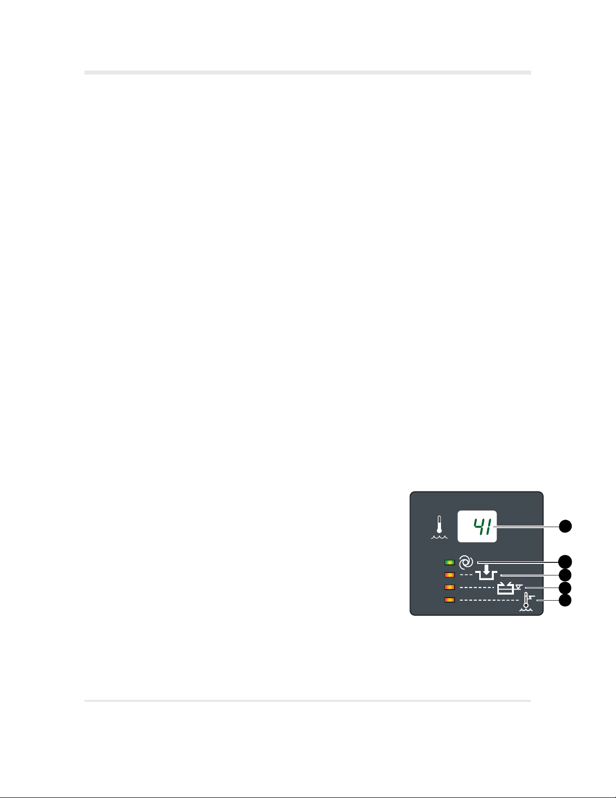
Display Panel
The Display Panel is located on the front of the HOTLINE
and provides continuous information about the operation of the
HOTLINE
®
Warmer. A liquid crystal display (LCD) indicates
recirculating solution temperature. Just below the LCD, four lightemitting diodes (LEDs) indicate operation modes for the HOTLINE
Wa rm e r.
1 Recirculating Solution Temperature - The temperature is displayed
in degrees Celsius.
2 Operating - The green LED illuminates when the power is turned
on and the HOTLINE
®
Fluid Warming set is properly installed.
®
Warmer
®
3 Check Disposables - The red LED illuminates and an audible
attention signal beeps when the HOTLINE
®
Fluid Warming Set is
not properly installed.
4 Add Solution - The red LED illuminates and an audible attention
signal beeps when the level in the reservoir is low and additional
solution must be added.
5 Over Temperature - The red LED illuminates and an audible
warning signal beeps when the recirculating solution is over the
acceptable temperature for safe use.
®
14 HOTLINE
Blood and Fluid Warmer | Operator’s Manual
o
C
1
2
3
4
5
Page 19

SECTION 6 • Operation
1.4 LITERS
Power and Alarm Test Panel
The Power and Alarm Test Panel is located on the left side of the
HOTLINE
®
Warmer next to the reservoir. This panel contains two
pressure-sensitive buttons that are activated when pressed, and the
ON/OFF switch.
1 Over Temperature Test Button - The Over Temperature Test is
used to confirm the proper operation of the Over Temperature
circuitry.
2 Alarm Test Button - The Alarm Signal Test is used to confirm
proper operation of the visual and audible alarms.
3 Power ON/OFF Switch - The black switch toggles to turn power
ON and OFF.
Reservoir Level Display
a
The reservoir for the recirculating solution is located on the left side of
the HOTLINE
®
Warmer, next to the Power and Alarm Test Panel. The
level of the recirculating solution is visible in the reservoir. Two symbols
indicate the maximum (a) and minimum (b) solution level
requirements.
b
HOTLINE
®
Blood and Fluid Warmer | Operator’s Manual 15
Page 20

SECTION 6 • Operation
Modes of Operation
The HOTLINE® Warmer operation is defined in the following modes:
• OFF Mode
•ON/Operating Mode
•Check Disposables Mode
• Add Recirculating Solution Mode
• Over Temperature Alarm Mode
The description of each mode includes a definition of the mode, activation
and/or monitoring of the mode, mode characteristics, and method to clear
the mode state.
OFF Mode
The power switch is in the OFF position (
a) and the HOTLINE
Warmer is turned off.
ON/Operating Mode
The power switch is in the ON position (
b) and the HOTLINE
Warming Set has been properly installed.
Mode Characteristics
• The green Operating LED (c) illuminates.
• The reservoir temperature display will begin to increase.
®
• The recirculating solution path in the HOTLINE
Fluid
Warming Set will automatically prime.
Check Disposables Mode
The Check Disposables mode indicates a missing or improperly
installed HOTLINE
Mode characteristics
®
Fluid Warming Set.
• The green Operating LED on the Display Panel turns off.
®
®
Fluid
a
b
c
d
• Τhe red Check Disposables LED (
d) on the Display Panel
illuminates.
• The audible alarm sounds and repeats approximately every two
seconds.
• The recirculating solution stops circulating.
®
16 HOTLINE
Blood and Fluid Warmer | Operator’s Manual
Page 21

SECTION 6 • Operation
To clear this mode, check that the Twin-Tube Connector on the
HOTLINE
®
Fluid Warming Set is firmly inserted in the socket.
Add Recirculating Solution Mode
The Add Recirculating Solution mode indicates that the solution level
in the reservoir is below its minimum level.
Mode characteristics
• The green Operating LED on the Display Panel turns off.
a
• The red Add Solution LED (
a) on the Display Panel illuminates.
• The audible alarm sounds and repeats approximately every two
seconds.
• The recirculating solution stops circulating.
To clear this mode, add recirculating solution to the reservoir.
Over Temperature Alarm Mode
The Over Temperature Alarm mode indicates that the temperature of
the recirculating solution is at or above 43.1°C.
Mode characteristics
• The green Operating LED on the Display Panel turns off.
• The red Over Temperature LED (
b
illuminates.
b) on the Display Panel
• The audible alarm sounds and repeats approximately every two
seconds.
• The recirculating solution stops circulating.
®
HOTLINE
Blood and Fluid Warmer | Operator’s Manual 17
Page 22

SECTION 7 • Operating Instructions
SECTION 7
Operating Instructions
The Operating Instructions are grouped into five segments. Read through
each segment BEFORE performing a procedure.
WARNINGS
WARNINGS
• Set-up, priming, and use require aseptic technique as per
applicable institutional policies and procedures.
• Grounding reliability can only be achieved when MAINS power
cords are connected to a properly grounded receptacle. Risk of
electrical shock exists if the equipment is not connected to a
properly grounded receptacle.
Step 1 - Set Up the HOTLINE® Warmer
1 Check that the level is above the minimum level mark (a) on the
reservoir. Add recirculating solution to the reservoir through the
fill-port if required.
2 Check the condition of the HOTLINE
®
Warmer with a visual
inspection before using. Remove from service any HOTLINE®
Warm e r t h a t s h o ws physical damage.
3 Plug the
HOTLINE
®
Warmer into properly grounded power outlet.
Step 2 - Set Up the HOTLINE® Fluid Warming Set
WARNINGS
WARNINGS
•The HOTLINE® Fluid Warming Set is a single-use device and is
not intended for re-sterilization.
• Do not use HOTLINE
securely in place, else flow path may not be sterile and may
cause death or serious injury.
®
Fluid Warming Set if the caps are not
a
18 HOTLINE
Continued
®
Blood and Fluid Warmer | Operator’s Manual
Page 23

SECTION 7 • Operating Instructions
o
Continued form previous page
WARNINGS
WARNINGS
• Prime the recirculating solution path before connecting to the
intravenous extension set. This is to confirm that there is not a
breach between the recirculating solution path and intravenous
path. If fluid exits the patient end of the HOTLINE
®
Fluid
Warming Set before connecting to the intravenous extension
set, remove and replace HOTLINE
®
Fluid Warming Set.
To set up the HOTLINE® Fluid Warming Set, you will need the following:
o
C
HOTLINE
Fluid Warmer
•HOTLINE
a
• Intravenous administration set
®
Warmer
• Intravenous fluid or blood
• Extension Set, 20cm (8") or less in length (optional)
1 Remove the reflux plug (if present) from the socket on the right
side of the HOTLINE® Warm e r.
2 Plug the Twin-Tube Connector on the
HOTLINE
®
Fluid Warming
Set (a) into the socket.
3 Turn ON the power switch.
• The green Operating LED on the Display Panel illuminates.
• The recirculating solution temperature display will begin to
increase.
• The recirculating solution path in the HOTLINE
®
Fluid
Warming Set will automatically prime.
4 Remove the end cap and inspect the patient end of the HOTLINE®
Fluid Warming Set for leaks to confirm the integrity of the
intravenous pathway.
®
HOTLINE
Blood and Fluid Warmer | Operator’s Manual 19
Page 24

SECTION 7 • Operating Instructions
Step 3 - Connect the Intravenous Administration Set
WARNINGS
WARNINGS
• Remove all air from the intravenous fluid lines before
connecting to the patient. Failure to do so may result in
introduction of air to the patient, which may contribute to
serious patient injury or death.
• Do not stick the HOTLINE
®
Fluid Warming Set with needles, as
this will breach the I.V. path and compromise the integrity of the
patient intravenous line. If a Disposable Set with a breached
recirculating solution path/intravenous path is used, then
patient illness may occur because of the HOTLINE
®
Warmer's
recirculating solution entering the patient's blood stream.
1 Connect the I.V. fluid and the intravenous administration set to the
HOTLINE
2 Fully prime the intravenous administration set, the
®
Fluid Warming Set.
HOTLINE
Fluid Warming Set, and patient extension set (if used).
3 Connect the distal end of the
HOTLINE
®
Fluid Warming Set to
the patient's intravenous access site without entrapping air.
Step 4 - Using the HOTLINE® Warmer
WARNINGS
WARNINGS
• Activation of the Over Temperature warning signal indicates
that warming has stopped and immediate operator intervention
is required to clear the over temperature condition or to remove
the device from service.
®
1 Wait until the recirculating solution temperature display reaches
41
°C, which indicates the HOTLINE
®
Warmer is ready for use.
2 Adjust the rate of I.V. flow using the clamp on the intravenous
administration set.
Note: Do not kink the Disposable Set. Do not restrict the circulation
of the solution through the tubing.
®
20 HOTLINE
Blood and Fluid Warmer | Operator’s Manual
Page 25

SECTION 7 • Operating Instructions
Step 5 - After Use
WARNINGS
WARNINGS
• Blood and blood products could contain pathogenic organisms.
Failure to follow institutional policy and procedures for
biomedical-hazardous materials could lead to exposure to
harmful pathogens.
1 Turn OFF the power switch.
o
C
HOTLINE
Fluid Warmer
a
2 Remove the
HOTLINE
®
Fluid Warming Set, and insert the reflux
plug (a) into the socket.
3 After use, handle and dispose of the
HOTLINE
®
Fluid Warming
Set as a potential biohazard.
Note: Properly discard the HOTLINE® Fluid Warming Set in containers marked for biohazardous materials. Dispose by incineration, or follow hospital policies and procedures applicable for the disposal of
biohazardous material.
4 Wipe down the external surfaces of the HOTLINE® Warm e r w i t h
mild detergent, water, and a soft cloth. For external disinfection, a
10% bleach solution may be used.
Storage
Store the HOTLINE
extreme temperatures. See Section 13,
®
Warmer in a cool, dry place. Do not expose to
Specifications
, for more details.
HOTLINE
®
Blood and Fluid Warmer | Operator’s Manual 21
Page 26

SECTION 8
Troubleshooting
SECTION 8 • Troubleshooting
Only authorized personnel should perform any routine maintenance and
repairs to the HOTLINE
Problem Check the following
No power
Check Disposables
alarm
Add Recirculating
Solution alarm
Over Temperature
alarm
®
Warmer.
®
1 Confirm that the HOTLINE
Warmer is plugged in
properly.
2 Confirm that the power switch is in the ON position.
®
Note: If the HOTLINE
Warmer is plugged in and the
power switch is turned ON, the green or red LED will
illuminate.
®
Confirm that the HOTLINE
Fluid Warming Set is
properly installed.
• Push the Twin-Tube Connector firmly into the
®
socket on the right side of the HOTLINE
Warmer.
Check the level in the reservoir and add recirculating
solution to the maximum level.
1 Check the HOTLINE
®
Fluid Warming Set for kinks or
other restrictions.
2 Check for air lock:
a Turn the power switch OFF, remove the HOTLINE
Fluid Warming Set, and gently shake HOTLINE®
Warmer to dislodge air.
®
b Plug in the HOTLINE
Fluid Warming Set and turn
power switch ON.
c If there are no restrictions or air present, remove
®
the HOTLINE
Warmer from service and return it
for repair or replacement.
®
Hot cabinet Check for blocked air vents on the bottom or the back of
the HOTLINE
Note: Room temperature above 42
HOTLINE
®
Warmer.
°C may cause the
®
Warmer to shut down and the Over
Temperature alarm to activate. In this unusual
situation, turn the power switch OFF and allow the
®
HOTLINE
Warmer to cool down before returning it
to service.
Difficult to install the
HOTLINE
®
Fluid
Lubricate O-rings in the socket. Refer to Section 10,
Maintenance, for the procedure.
Warming Set
®
22 HOTLINE
Blood and Fluid Warmer | Operator’s Manual
Page 27

SECTION 8 • Troubleshooting
Problem Check the following
Recirculating
solution leaks at the
socket where the
®
HOTLINE
Fluid
Warming Set plugs
into the HOTLINE
®
Warmer
Electrical
interference receiving or
transmitting
Replace O-rings. Use the O-ring Replacement Kit: P/N
80-04-001. Refer to Section 10, Maintenance, for the
procedure.
®
1 Move the HOTLINE
Warmer away from the device in
question.
2Plug the HOTLINE® Warmer into a separate electrical
circuit.
• If the problem continues, notify Smiths Medical or
an authorized representative for assistance.
HOTLINE
®
Blood and Fluid Warmer | Operator’s Manual 23
Page 28

SECTION 9
Te s t i n g
The HOTLINE® Warmer should be tested by hospital biomedical
personnel prior to placing it in service. All testing and maintenance should
be performed by qualified personnel. If qualified personnel are not
available, contact Smiths Medical.
SECTION 9 • Testing
If the HOTLINE
the listed tests, discontinue use of the HOTLINE
®
Warmer and any installed accessories do not pass any of
®
Warmer and remove
from service. Contact Smiths Medical or an authorized representative for
service.
WARNINGS
WARNINGS
• If any visual indicator does not illuminate or the audible signal
does not sound, do not use the Fluid Warmer. Remove the
device from service immediately.
Note: Alarm testing requires a HOTLINE® Fluid Warming Set to be
installed and that the HOTLINE
ating mode.
®
Warmer be turned ON and in the Oper-
Alarm Signal Test
The Alarm Signal Test is used to confirm proper operation of the visual
and audible alarm indicators.
1 Press and hold the Alarm Test button (a).
a
2 Observe the following:
• The green Operating LED turns off.
• Three red LEDs (Check Disposables, Add Solution, and Over
Temperature) illuminate.
• The audible alarm sounds and repeats approximately every two
seconds.
®
24 HOTLINE
Blood and Fluid Warmer | Operator’s Manual
Page 29

Over Temperature Test
SECTION 9 • Testing
a
of approximately 41°C to 42°C.
1 Press and hold the Over Temperature button (a).
2 Observe the following:
• The recirculating solution Over Temperature Alarm activates at
43°C.
The HOTLINE® Warmer should be running at an operating temperature
b
• The green Operating LED turns off.
• The red Over Temperature LED (
b) illuminates.
• The audible alarm sounds and repeats approximately every two
seconds.
3 Stop pressing the Over Temperature Test button to stop the test.
c
Add Recirculating Solution Test
The HOTLINE® Warmer is equipped with a float switch, which senses the
recirculating solution level in the reservoir. When the recirculating
solution is too low, the Add Recirculating Solution Alarm will activate.
d
1 Remove the fill-port plug (c) on the reservoir.
e
2 Gently depress the float switch (
d). (This action will simulate the
low solution condition.)
Note: Use a non-metal tool to depress the float switch because the
float switch contains a magnet.
3 Observe the following:
• The green Operating LED turns off.
• The red Add
Recirculating Solution LED (e) illuminates.
• The audible alarm sounds and repeats approximately every two
seconds.
®
HOTLINE
Blood and Fluid Warmer | Operator’s Manual 25
Page 30

Check Disposables Test
o
SECTION 9 • Testing
An interlock switch/sensor, located in the socket on the right side of the
®
HOTLINE
Warming Set. When the switch does not sense a HOTLINE
Warmer, senses a properly installed HOTLINE® Fluid
®
Fluid
Warming Set, the Check Disposables alarm activates.
1 Slowly remove the HOTLINE® Fluid Warming Set (a) from the
HOTLINE
®
Warmer socket.
2 Observe the following actions:
• The green Operating LED turns off.
• The red Check Disposables LED (
b) illuminates.
• The audible alarm sounds and repeats approximately every two
seconds.
Note: In any alarm condition, the pump should not be running. A
small amount of solution dripping from the disconnection is normal
and should stop in a few seconds.
Temperature Verification of the Recirculating Solution
Use the Level 1® TEMP CHECK Thermometer (HLTA-40) to verify the
displayed recirculating solution temperature. Other methods of
temperature verification may be inaccurate.
HOTLINE
Fluid Warmer
b
a
o
C
TEMP CHECK provides an accurate reading of the highest temperature of
the recirculating solution. Because the temperature of the reservoir is
typically 0.5°C to 2.0°C lower than the temperature from the heater, and
the temperature of the recirculating solution begins to drop due to the
effect of ambient temperature on the HOTLINE
®
Fluid Warming Set, the
highest temperature of the solution is just after it leaves the heater. During
the temperature verification test, the TEMP CHECK is positioned on the
right side of the HOTLINE
solution just after it leaves the heater and before it enters the HOTLINE
®
Warmer attached to the socket and senses the
®
Fluid Warming Set.
Refer to the TEMP CHECK HLTA-40 Thermometer Operator's Manual
for complete Temperature Verification and Calibration Instructions.
®
26 HOTLINE
Blood and Fluid Warmer | Operator’s Manual
Page 31

SECTION 9 • Testing
To verify the recirculating solution temperature, you will need the
following:
• TEMP CHECK (HLTA-40)
•HOTLINE
•HOTLINE
®
Warmer
®
Fluid Warming Set
To Verify the Recirculating Solution Temperature:
1 Plug the HOTLINE® Warmer into a power outlet.
2 Place the TEMP CHECK on the top right corner of the
HOTLINE
the HOTLINE
3 Plug the Twin-Tube Connector on the
®
Warmer and plug it into the socket on the right side of
®
Warme r.
HOTLINE
®
Fluid Warming
Set into the socket on the right side of the TEMP CHECK.
4 Remove the black label from the auxiliary outlet on the back of the
HOTLINE
®
and plug in the TEMP CHECK power cord.
Note: The auxiliary outlet is for use only with Smiths Medical
accessories.
5 Tu r n O N t h e HOTLINE® Warmer. Allow 15 minutes for the
temperature to stabilize.
6 If the TEMP CHECK display indicates a temperature between 41
°C
and 42°C, and the HOTLINE® Warmer display equals the TEMP
CHECK display, recirculating solution verification is complete.
Refer to the TEMP CHECK Manual for OVERTEMP ALARM
verification.
7 If the TEMP CHECK display does not indicate a temperature
between 41
°C and 42°C, refer to the TEMP CHECK Manual for
calibration instructions.
HOTLINE
®
Blood and Fluid Warmer | Operator’s Manual 27
Page 32

Periodic Electrical Testing
Electrical Safety Tests must be performed by qualified personnel authorized
by the institution to perform such testing. The Safety Tests must be
performed and documented at least once per year, or according to
institutional policy. These tests include but are not limited to:
• Leakage current
•Ground bond test
Leakage Current
Leakage current must be tested according to methods and pass/fail
criteria described in UL 2601-1 or EN 60601-1. Leakage current must be
performed with the heater circuit in the full ON condition. To achieve
this condition, perform the test when the reservoir is at room
temperature. When the HOTLINE
temperature is rapidly rising, but still below 41°C, the heater circuit is in
a full ON condition.
®
Warmer is first turned on and the
SECTION 9 • Testing
Note: The HOTLINE
HOTLINE
HOTLINE
®
Fluid Warming Set is required to correctly operate the
®
Warmer and perform leakage current testing. Do not defeat
the sensing interlocks or try to operate the HOTLINE
HOTLINE
®
Fluid Warming Set in place.
®
Warmer is equipped with sensing interlocks. A
®
without a
Ground Bond Test
Ground bond test must be tested according to methods and pass/fail
criteria described in UL 2601-1 or EN 60601-1.
28 HOTLINE
®
Blood and Fluid Warmer | Operator’s Manual
Page 33

SECTION 10
Maintenance
SECTION 10 • Maintenance
Only authorized personnel should perform any routine maintenance and
repairs to the HOTLINE
®
Warmer. Maintenance is scheduled with each
use, every 30 days, and every 12 months. The tasks are described below.
Maintenance Performed with Every Use
CAUTIONS
• Do not autoclave.
• Do not immerse any part of the HOTLINE
Clean and inspect the HOTLINE® Warmer.
Clean the Exterior
• Clean the entire HOTLINE
®
Warmer after every use. Use only
mild detergents, water, and a soft cloth.
Note: Do not use abrasive cleaning agents, solvents, or cold
sterilants. These agents will cause the device to crack.
®
Warmer in liquids.
• For disinfecting external surfaces, use a 10% bleach solution.
General Inspection
• Check the condition of the HOTLINE
®
Warmer with a visual
inspection before using. Remove from service any HOTLINE
Warmer that shows physical damage.
•If the HOTLINE
®
Fluid Warming Set does not install easily,
lubricate the O-Rings as directed in the following section.
®
HOTLINE
Blood and Fluid Warmer | Operator’s Manual 29
®
Page 34

SECTION 10 • Maintenance
Disinfect the Reservoir and Change the Recirculating Solution
Disinfect the reservoir and change the recirculating solution every 30 days
or every 12 months based on the recirculating solution used for the
HOTLINE® Warmer. Refer to the following table for the maintenance
schedule
Recirculating Solution Preparation Maintenance
.
0.3% Hydrogen Peroxide
Solution
Sterile Distilled
Water
35% Isopropyl Alcohol
Solution
Note: Use sterile distilled water only, not tap water. Failure to do so may cause
build-up of mineral deposits in the recirculating solution path, which may impair
heater performance.
Mix 140 ml of 3% hydrogen
peroxide with 1,260 ml of
sterile distilled water.
Use sterile distilled water. Replace solution and
Mix 700 ml of 70% isopropyl
alcohol with 700 ml of sterile
distilled water.
Replace solution and
disinfect reservoir every
12 months.
disinfect reservoir every
30 days.
Replace solution and
disinfect reservoir every
30 days.
Disinfect the Reservoir
1 Unplug the HOTLINE® Warmer before servicing.
2 Remove the drain tube from the holder on the rear of the
HOTLINE
3 In
vert the drain tube (a) and place a container under the end of the
tube
®
Warm e r.
. Remove the end cap (b) and drain the recirculating solution
into the container.
c
4 When all the recirculating solution has drained from the reservoir,
replace the end cap and insert the drain tube back in the holder.
5 Prepare a 0.3% hydrogen peroxide solution by mixing 140 ml of 3%
hydrogen peroxide solution and 1,260 ml of sterile distilled water.
6 Remove the fill-port plug (
c), fill the reservoir with the hydrogen
peroxide solution, and replace the fill-port plug.
®
30 HOTLINE
Blood and Fluid Warmer | Operator’s Manual
a
b
Page 35

SECTION 10 • Maintenance
o
o
C
HOTLINE
Fluid Warmer
a
7 Remove the reflux plug from the socket if required, and insert a
HOTLINE
®
Fluid Warming Set (a) (L-70, L-70NI, L-80) into the
socket.
8 Tu r n t h e H O T L I N E
®
Warmer ON, and let the recirculating
solution circulate for a 30-minute disinfection period.
9 Tu r n t h e H O T L I N E
®
Warmer OFF and unplug the power cord.
10 Empty the reservoir.
11 Remove the HOTLINE
®
Fluid Warming Set and discard
according to established hospital procedures.
These suggested instructions are designed to be used in conjunction
with established hospital procedures.
Add Recirculating Solution
CAUTIONS
• Do not fill the HOTLINE® Warmer reservoir with a HOTLINE®
Fluid Warming Set or a TEMP CHECK in place. Failure to
remove the HOTLINE
procedure may result in an air lock in the HOTLINE
®
Fluid Warming Set before the fill
®
Warmer.
1 Prepare the recirculating solution.
2 Remove the fill-port plug.
3
Fill the reservoir with 1.4 liters of recirculating solution.
4 Replace the fill-port plug.
Maintenance Performed Every 30 Days
Disinfect the Reservoir and Change Recirculating Solution for
Sterile Distilled Water and 35% Isopropyl Alcohol Solution
Refer to
procedure in this section.
HOTLINE
Disinfect the Reservoir and Change the Recirculating Solution
®
Blood and Fluid Warmer | Operator’s Manual 31
Page 36

Lubricate O-Ring Seals
SECTION 10 • Maintenance
1 Place a small amount of silicone grease on a cotton swab.
2 Apply silicone grease along the O-Rings inside the socket (
located on the right side of the
HOTLINE
®
Warmer.
a)
Silicone lubricant is available from Smiths Medical, (Silicone
lubricant P/N 80-04-002).
Maintenance Performed Every 12 Months
Disinfect the Reservoir and Change Recirculating Solution for
0.3% Hydrogen Peroxide Solution
Refer to
procedure in this section.
Replace O-Rings
1 Remove the socket head screws (b) with a 0.31cm (1/8") hex
2 Remove the faceplate, being careful not to damage the micro-switch
Disinfect the Reservoir and Change the Recirculating Solution
wrench.
lever.
o
C
HOTLINE
Fluid Warmer
o
C
HOTLINE
Fluid Warmer
a
b
3 Remove the old O-rings and clean the sockets with a cotton swab.
4 Apply silicone lubricant to two new O-rings and install into the
sockets.
5 Reassemble in reverse order, being careful not to damage the micro-
switch lever. (O-Ring Kit: P/N 80-04-001)
Testi n g HOTLI N E® Warmer Operation
Perform all the tests described in the testing section of this manual. See
Te s t i n g
Section 10,
the tests.
32 HOTLINE
. The Scheduled Maintenance Checklist below also lists
®
Blood and Fluid Warmer | Operator’s Manual
Page 37

SECTION 10 • Maintenance
Maintenance Log
All maintenance and testing should be done by qualified personnel.
Regularly scheduled maintenance ensures proper functioning of the
equipment. Refer to the table below for required tasks and frequency of
routine maintenance.
Maintenance Checklist
Task Every Use Every 30 Days Every 12 Months
Clean the Exterior
General Inspection
Disinfect the Reservoir and
Change Sterile Distilled
Water or Isopropyl Alcohol
solution
Lubricate the O-Rings
Disinfect the Reservoir and
Change the Hydrogen
Peroxide Solution
Replace the O-Rings
Alarm Test
Add Solution Test
Check Disposables Test
Over Temperature Test
Verify Temperature
Calibration
Electrical Safety Tests
®
HOTLINE
Blood and Fluid Warmer | Operator’s Manual 33
Page 38

SECTION 11
Limited Warranty
SECTION 11 • Limited Warranty
Smiths Medical ASD, Inc. (the “Manufacturer”) warrants to the Original
Purchaser that the HOTLINE
“HOTLINE
®
Warmer”), not including accessories, shall be free from
®
Blood and Fluid Warmer (the
defects in materials and workmanship under normal use, if used in
accordance with this Operator’s Manual, for a period of one year from the
actual date of sale to the Original Purchaser. THERE ARE NO OTHER
WARRANTIES.
This warranty does not cover normal wear and tear and maintenance
items, and excludes any accessory items or equipment used with the
HOTLINE
®
Warmer.
Subject to the conditions of and upon compliance with this Limited
Warranty, the Manufacturer will repair or replace at its option without
charge (except for a minimal charge for postage and handling) any
HOTLINE
®
Warmer (not including accessories) which is defective if a
claim is made during such one-year period.
The following conditions, procedures, and limitations apply to the
Manufacturer's obligation under this warranty:
A. Parties Covered by this Warranty: This warranty extends only to the
Original Purchaser of the HOTLINE
®
Warmer. This warranty does
not extend to subsequent purchasers. The Original Purchaser may be
medical personnel, a hospital, or institution which purchases
HOTLINE
®
Warmers for treatment of patients. The Original
Purchaser should retain the invoice or sales receipt as proof as to the
actual date of purchase.
B. Warranty Performance Procedure: Notice of the claimed defect must
be made in writing or by telephone to the Manufacturer as follows:
Customer Service Department, Smiths Medical ASD, Inc., 160
Weymouth Street, Rockland, MA 02370, (800) 258-5361. Notice to
the Manufacturer must include date of purchase, model and serial
number, and a description of the claimed defect in sufficient detail to
allow the Manufacturer to determine and facilitate any repairs which
may be necessary. AUTHORIZATION MUST BE OBTAINED
PRIOR TO RETURNING THE HOTLINE
authorized, the HOTLINE
34 HOTLINE
®
Warmer must be properly and carefully
®
Blood and Fluid Warmer | Operator’s Manual
®
WARMER . If
Page 39

SECTION 11 • Limited Warranty
packaged and returned to the Manufacturer, postage prepaid. Any
loss or damage during shipment is at the risk of the sender.
C. Conditions of Warranty: The warranty is void if the HOTLINE
Warmer has been 1) repaired by someone other than the
Manufacturer or its authorized agent; 2) altered so that its stability
or reliability is affected; 3) misused; or 4) damaged by negligence or
accident. Misuse includes, but is not limited to, use not in
compliance with the Operator's Manual or use with non-approved
accessories. Removal or damage to the HOTLINE
®
Warmer’s serial
number will invalidate this warranty.
D. Limitations and Exclusions: Repair or replacement of the
HOTLINE
®
Warmer or any component part thereof is the
EXCLUSIVE remedy offered by the Manufacturer. The following
exclusions and limitations shall apply:
1. No agent, representative, or employee of the Manufacturer has
authority to bind the Manufacturer to any representation or
warranty, expressed or implied.
2. THERE IS NO WARRANTY OF MERCHANTABILITY OR
FITNESS OR USE OF THE HOTLINE
®
WARMER FOR ANY
PARTIC ULA R PU RPOS E.
3. The HOTLINE
®
Warmer can only be used under the supervision
of medical personnel whose skill and judgment determine the
suitability of the HOTLINE
®
Warmer for any particular medical
treatment.
®
4. All recommendations, information, and descriptive literature
supplied by the Manufacturer or its agents are believed to be
accurate and reliable, but do not constitute warranties.
The Manufacturer disclaims responsibility for the suitability of the
HOTLINE
medical complications resulting from the use of the HOTLINE
®
Warmer for any particular medical treatment or for any
®
Warmer.
The Manufacturer shall not be responsible for any incidental damages or
consequential damages to property, loss of profits, or loss of use caused by
any defect or malfunction of the HOTLINE
®
Warmer.
This warranty gives the Original Purchaser specific legal rights, and the
Original Purchaser may have other legal rights which may vary from state
to state.
®
HOTLINE
Blood and Fluid Warmer | Operator’s Manual 35
Page 40

SECTION 12
Service
All service must be performed by Smiths Medical or an authorized service
representative. Service by any other person or organization voids the
warranty and transfers liability for malfunctions of the device to the
servicing organization.
Warranty Service
Devices received for repair that have not been obviously abused or impact
damaged and are still under warranty will be promptly repaired and
returned at no charge. See the limited warranty section of this manual. A
no-charge purchase order is requested for tracking.
Non-Warranty Work
SECTION 12 • Service
Devices received that have suffered obvious abuse or impact damage and
devices no longer under warranty will be promptly inspected and a verbal
estimate of repair cost will be provided. A purchase order will be required
from the hospital consistent with the verbal estimate. A written estimate
will be provided upon request.
Before returning the HOTLINE
Medical for Returned Goods Authorization. Be sure that ALL recirculating
solution is drained from the device before packing the HOTLINE
Warmer for shipment.
Note: The HOTLINE
shipment or it will be immediately returned as received.
®
Warmer must be cleaned and disinfected for repair
®
Warmer for service, contact Smiths
®
Additional Documentation
Upon request Smiths Medical will provide the following documentation:
• Circuit diagrams
• Components parts list(s)
• Description of function
• Service and calibration instructions
36 HOTLINE
®
Blood and Fluid Warmer | Operator’s Manual
Page 41

SECTION 12 • Service
Disposal Information
The HOTLINE® Warmer contains lead that is used in solder of electric
assembly. When you are ready to dispose of the device, observe federal,
state, and local codes or requirements for disposal of hazardous materials
and for recycling of solid waste materials that may impact the
environment.
Service Contacts
Contact your Smiths Medical Technical Service Department or Smiths
Medical distributor at:
USA/Canada
Smiths Medical ASD, Inc.
Anesthesia and Safety Devices Division
160 Weymouth Street
Rockland, MA 02370 USA
USA/Canada 1-800-258-5361
International +1-781-878-8011
European Representative
Smiths Medical International Ltd
Watford, Herts, WD24 4LG, UK
Tel +44 (0) 1923 246434
Fax +44 (0) 1923 240273
Australian Representative
Smiths Medical Australasia Pty. Ltd.
61 Brandl Street,
Eight Mile Plains, QLD 4113, Australia
Tel +61 (0) 7 3340 1300
Fax +61 (0) 7 3340 1399
HOTLINE
®
Blood and Fluid Warmer | Operator’s Manual 37
Page 42

SECTION 13 • Specifications and Accessories
SECTION 13
Specifications and Accessories
System Specifications
Standard Compliance Guidelines
Product Safety EN 60601-1, UL 2601-1
EMC EN 60601-1-2, FCC 47 CFR Part 15,
Class B
Enclosure Protection IEC 60529 IP Code: IPX1
Fluid Warmers ASTM F2172-02
Physical Dimensions
Height, Overall 24.1 cm (9.5 inches)
Width, Overall 21.0 cm (8.3 inches)
Depth, Overall 17.8 cm (7.0 inches)
Weight, Dry 3.5 Kg (7.6 lbs)
Weight, Wet (with recirculating
solution)
Weight, Shipping 3.6 Kg (7.95 lbs)
Recirculating Solution
Capacity
Maximum Height on I.V. Pole 107 cm (42 inches)
Environmental Temperature Humidity [%]
Operation
Transportation
Storage
Thermal Temperature
Temperature Set Point
Over Temperature Set Point
Electrical Type
MAINS Power Input:
100V 100VAC, 50/60 H
115V 115VAC, 50/60 HZ, 3.0 Amps
230V 230VAC, 50/60 H
MAINS Auxiliary Supply Power
Output:
100V 100VAC, 50/60 H
115V 115VAC, 50/60 H
230V 230VAC, 50/60 HZ, 0.5 Amps
5.0 Kg (11.0 lbs)
1.4 L (0.37 gallons)
o
C to 45oC 10 to 95
10
o
C to 70oC 10 to 95
-20
-20oC to 70oC 10 to 95
o
C ± 0.1oC
41.9
o
C
43.1
Z, 3.8 Amps
Z, 1.5 Amps
Z, 1.0 Amps
Z, 1.0 Amps
38 HOTLINE
®
Blood and Fluid Warmer | Operator’s Manual
Page 43

SECTION 13 • Specifications and Accessories
Electrical Type
Protection Against Electrical
Shock
Mode of Operation Continuous
Type of Current Alternating
Ingress Protection Rating IPX1
Performance
Recirculating Solution
Te mper at u r e
Normothermic Flow Rates At gravity flow rates to 5,000 ml per hour
Class 1 Equipment, Type BF
Recirculating solution temperature reaches
37oC from ambient in about 4 minutes
The HOTLINE® Warmer is manufactured to be in compliance with UL
2601-1 (HL-90 115V) and EN 60601-1 (HL-90 230V).
Electromagnetic Compliance
HOTLINE® Warmer is certified to be in compliance with the European
Communities Council Directive relating to Electromagnetic Compatibility
(EMC): (89/336/EEC). Test methods and acceptance criteria as specified
in EN 60601-1-2 demonstrate conformance.
HOTLINE
®
Blood and Fluid Warmer | Operator’s Manual 39
Page 44

SECTION 13 • Specifications and Accessories
Electromagnetic Environmental Recommendations
Recommended separation distances between portable and mobile RF communications
®
equipment and the HOTLINE
Warmer
The HOTLINE® Warmer is intended for use in an electromagnetic environment in which radiated RF
®
disturbances are controlled. The customer or the user of the HOTLINE
Warmer can help prevent
electromagnetic interference by maintaining a minimum distance between portable and mobile RF
®
communications equipment (transmitters) and the HOTLINE
Warmer as recommended below, according
to the maximum output power of the communications equipment.
Rated maximum
output power of
transmitter
Separation distance according to frequency of transmitter m
150 kHz to 80 MHz
d=[3.5/V1]√P
80 MHz to 800 MHz
d=[3.5/E1]√P
800 MHz to 2.5 GHz
d=[7/E1]√P
W
0.01 0.116 0.116 0.233
0.1 0.368 0.368 0.737
1 1.16 1.16 2.33
10 3.69 3.69 7.38
100 11.66 11.66 23.33
For transmitters rated at a maximum output power not listed above, the recommended separation distance
d in metres (m) can be estimated using the equation applicable to the frequency of the transmitter, where P
is the maximum output power rating of the transmitter in watts (W) according to the transmitter
manufacturer.
NOTE 1 At 80 MHz and 800 MHz, the separation distance for the higher frequency range applies.
NOTE 2 These guidelines may not apply in all situations. Electromagnetic propagation is affected by absorption and reflection from
structures, objects and people
.
Accessories
Product Description
L-70
L-70NI
L-80
HOTLINE
HOTLINE
HOTLINE
L-10 Gas Vent
PC-8 T-Connector, 8” Patient Lead with Injection Port
YC-8 Y-Connector, 8” Patient Lead with Injection Port
40 HOTLINE
®
Fluid Warming Set with Injection Port
®
Fluid Warming Set without Injection Port
®
Warming Set with L-10 Gas Vent
®
Blood and Fluid Warmer | Operator’s Manual
Page 45

SECTION 14
o
Symbols
Symbols Definitions
Power switch in the ON position
Power switch in the OFF position.
ON/Operation
SECTION 14 • Symbols
o
Reservoir Temperature Display
C
Add Recirculating Solution
Check Disposables
Over Temperature
Maximum Reservoir Level
Minimum Reservoir Level
Alarm Test
Type BF Equipment
®
HOTLINE
Blood and Fluid Warmer | Operator’s Manual 41
Page 46

Symbols Definitions
Protected Against Dripping Water
Catalog Number
Serial Number
Part Number
Batch Code
Authorized Representative in the European
Community
SECTION 14 • Symbols
Manufacturer
Date of Manufacture
Quantity
Protective Earth [Ground]
Alternating Current
Do Not Reuse
Attention, see instructions for use
Electric Shock Hazard
42 HOTLINE
®
Blood and Fluid Warmer | Operator’s Manual
Page 47

Symbols Definitions
Latex Free
Caution: Federal (U.S.A.) law restricts this
device to sale by or on the order of a physician.
SECTION 14 • Symbols
CLASS 1
Device is class type 1 equipment
Protective earth terminal
Do not use if package is damaged.
Sterilized using ethylene oxide
Temperature Limitation
Humidity Limitation
Use by
Recyclable Product
HOTLINE
Device has been tested by National Technical
Systems, a nationally recognized technical
laboratory, to meet U.S. requirements for safety.
Collect separately for electrical and electronic
equipment.
CE Mark and Notified Body number (0473
indicates AMTAC)
®
Blood and Fluid Warmer | Operator’s Manual 43
Page 48

Index
Numerics
0.3% Hydrogen peroxide solution
maintenance schedule
preparation
35% Isopropyl alcohol solution
maintenance schedule
preparation
11, 30
11, 30
30
30
A
Accessories list 40
Add Recirculating Solution mode
Add Recirculating Solution test
Add Solution LED
Additional documentation
After Use
Alarm signal test
Alarm Test button
Alcohol (isopropyl) solution
Anesthetic use warning
Assembly instructions
Australian representative
Auxiliary electrical outlet
21
17
24
15
6
9
37
3
17
25
36
11, 30
B
Biohazardous material
disposal information
21
C
Canada service contact 37
Cautions
Change the recirculating solution
Check Disposables mode
Check Disposables Test
Clamp for I.V. pole
Clean exterior surfaces
Components
Connect the intravenous administration set
Contents
Contraindications
Controls
Conventions used in manual
7
L-10 Gas Vent
2
description
list
9
2
14
8
30
16
26
3
29
5
1
20
D
Description
components
HOTLINE Fluid Warming Sets
HOTLINE Warmer
Disinfect the reservoir
Display Panel
description
Disposal information
biohazardous materials
electrical device
Drain tube
2
4
2
10, 30
2, 14
14
37
21
37
3
E
Electrical safety tests 12, 28
Electrical specifications
Electromagnetic compliance
Electromagnetic environmental
recommendations
Environmental specifications
European representative
38
39
40
38
37
F
Fill-port plug 3
Float switch
3
G
Grounding reliability 7, 18
Guidelines for safe use
5
H
HOTLINE Fluid Warming Sets
description
priming volume
Hydrogen peroxide solution
preparation
4
4
10, 11, 30
I
I.V. pole mounting height restrictions 9
Important safety information
Indications for use
Infusate delivery temperatures
1
5
13
44 HOTLINE
®
Blood and Fluid Warmer | Operator’s Manual
Page 49

Index
Intravenous administration set
connect
Isopropyl alcohol solution
20
11, 30
L
L-10 Gas Vent
warnings and cautions
LCD
14
LEDs
14
Light-emitting diodes (LEDs)
Liquid crystal display (LCD)
8
14
14
M
Maintenance 29
performed every 12 months
performed every 30 days
performed with every use
Maintenance schedule
recirculating solution
Modes of operation
Mounting to I.V. pole
16
31
29
11, 30
9
N
Non-Warranty work 36
O
OFF mode 16
ON/Operating mode
Operating LED
Operation modes
O-Rings
lubricate seals
replace
32
Over Temperature Alarm mode
Over Temperature LED
Over Temperature test
Over Temperature Test button
16
16
14, 16
32
17
25
P
Performance specifications 39
Physical specifications
Power and Alarm Test Panel
Power cord
Power ON/OFF switch
3
38
15
15
32
17
15
priming volume
HOTLINE Fluid Warming Sets
Principle of operation
13
4
R
Recirculating solution
change
30
maintenance schedule
preparation
protocols
Reflux plug
Replace
O-Rings
Reservoir
fill with recirculating solution
Reservoir level display
11, 30
11
3
32
3
11, 30
11
15
S
Service 36
Service contacts
Set Up the HOTLINE Fluid Warming Set
Set Up the HOTLINE Warmer
Socket
2
Specifications
electrical
environmental
performance
physical
thermal
Standard compliance guidelines
Sterile distilled water
maintenance schedule
Storage
Symbols
System specifications
21
41
37
18
18
38
38
38
39
38
38
38
30
38
T
Temperature
display
14
Over Temperature Alarm
Temperature verification of the recirculating
solution
Testing
Thermal specifications
26
24
38
17
HOTLINE
®
Blood and Fluid Warmer | Operator’s Manual 45
Page 50

Troubleshooting 22
Add Recirculating Solution alarm
Check Disposables alarm
electrical interference
hot cabinet
install HOTLINE Fluid Warming Set
no power
Over Temperature alarm
recirculating solution leaks
22
22
22
23
22
23
U
USA service contact 37
Using the HOTLINE Warmer
20
W
Warnings 5
L-10 Gas Vent
Warranty
Warranty service
34
8
36
Index
22
22
46 HOTLINE
®
Blood and Fluid Warmer | Operator’s Manual
 Loading...