

Page 1
Suitable for Installation within a ceiling void
Installation & User Guide
User Information:
This appliance can be used by children aged from 8 years and above and
persons with reduced physical, sensory or mental capabilities or lack of
experience and knowledge if they have been given supervision or
instruction concerning use of the appliance in a safe way and understand
the hazards involved. Children shall not play with the appliance. Cleaning
and user maintenance shall not be made by children without supervision
A means for disconnection from the supply mains having a contact
separation in all poles that provides full disconnection under overvoltage
category III conditions must be incorporated in the fixed wiring in
accordance with the wiring rules.
Ensure that the fan convector is switched-off before opening the cover.
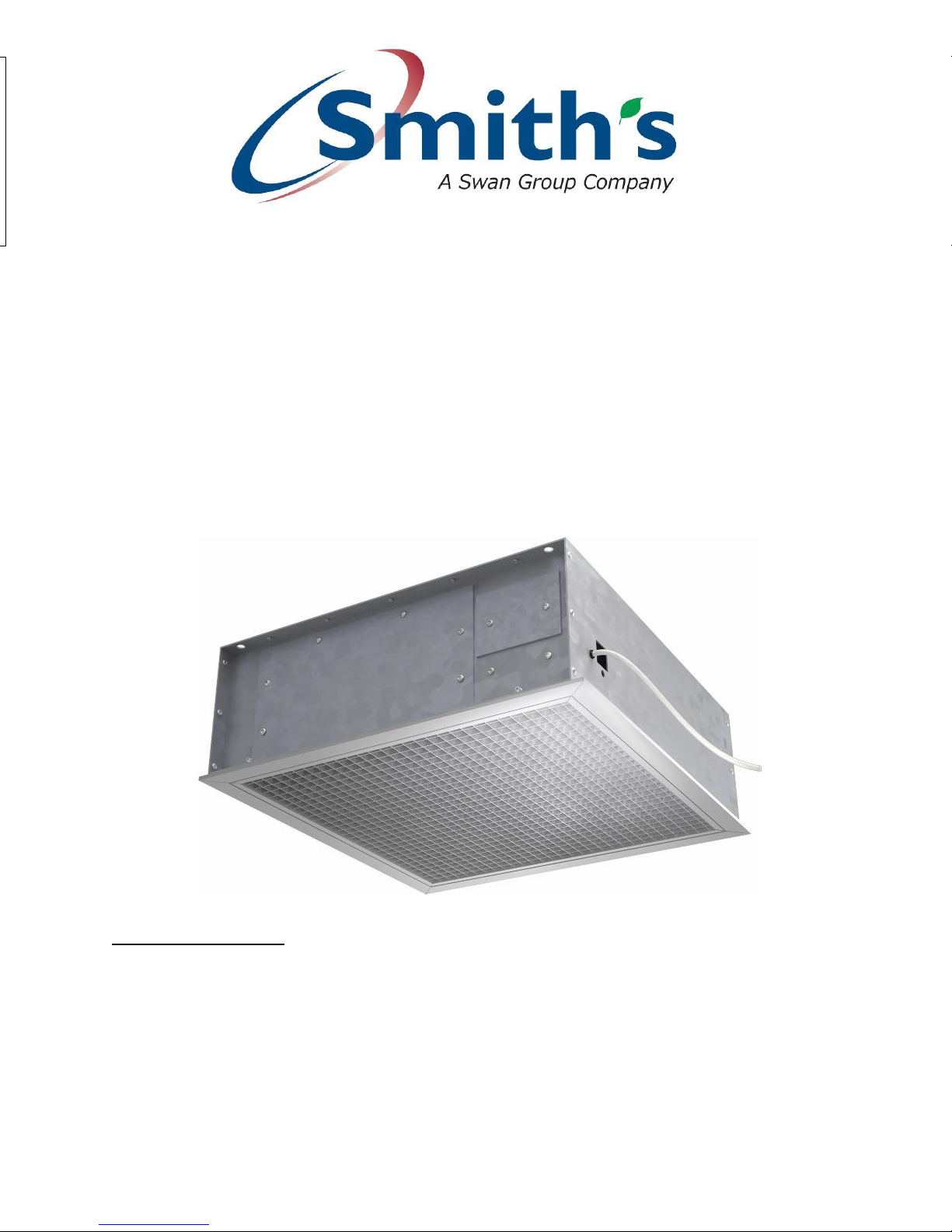
CASPIAN SKYLINE®
CT60 AC
Ceiling Level Fan Convector
Page 2
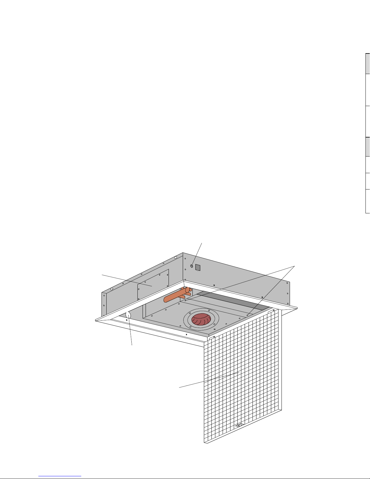
CABLE ENTRY
PIPE ENTRY
HINGED GRILLE
VALVE ACCESS PANEL
FILTER RETAINER
Introduction
This heater is designed to be installed into suspended T-bar and plasterboard ceilings (The
minimum height of the void into which the unit will be installed should be a minimum of 250mm).
User Information:
This heater must not be installed in wet rooms or other high humidity areas.
This heater is designed for use on standard two-pipe pumped central heating systems with a
maximum water temperature of 86° C and a maximum pressure of 6 bar (88lbs/in²).
Pipe connections are 22mm and either pipe may be used as flow or return.
This heater is classified as a fixed appliance and the electrical connection should be via a 3A fused
spur. The fused spur must not be directly below the heater but should be accessible after
completion of the installation. This heater must be earthed.
It is recommended that this heater is wired via a remote room thermostat.
To avoid the possibility of vibration this heater must be fitted to a flat even surface.
This heater is fitted with a 35°C Low Limit Stat (L.T.C).
To conform to Building Regulations Part L (Part J in Scotland), a remote room thermostat can be
used in conjunction with this heater. Refer to the instructions supplied with the thermostat.
Please note the guarantee may be invalidated if this product is not installed and used in
accordance with these instructions.
For further details please contact our Technical Support on 01245 324560.
Figure 1
2
Fault Finding
1) The fan does not run on any switch setting.
a) Check the power supply is switched ON.
b) Check the fuse in the fused spur.
c) Check the wiring at the fused spur.
2) No heat output.
a) Vent any trapped air from the system (with the heating system turned OFF).
b) Check the central heating is switched ON.
c) If a thermostat is fitted ensure it is calling for heat.
d) Balance the central heating system if installed on the same circuit as panel radiators and
e) Increase the boiler water temperature.
In the event of difficulty please contact our technical help-line on 01245 324560. It will be helpful if
you do not disconnect the heater from the central heating system.
A product brochure containing full technical specifications and list prices is available to
download from our website or in hard copy from our office. Also available on our website are
price lists, individual product datasheets, installation & user guides, where to buy, who to
Alternatively contact our office 9.00am to 5.00pm Monday to Thursday, 9.00am to 4.00pm to
Optional Accessories
Optional accessories are available to offer additional control or functionally not offered by the heater
in its standard configuration.
Electrical Accessories
Wall Switch Kit CT60AC WSC
Allows an on/off wall switch to be mounted on the wall to control heater.
Suitable cable to connect the switch from the heater to the switch is not supplied.
Adjustable low temperature cut-out CT60 ALTC T3
This enables the end user to precisely select the temperature at which the fans will switch on when
combined with different heat sources.
Miscellaneous Accessories
Caspian 22mm Flexible Hoses CAS22FH
Replacement air filters
For accessories or spares please contact either your supplier or Smith’s Environmental
Products Ltd.
Page 3
HEATER UNIT
GRILLE
T-BAR
HANGING
BOLT
HANGING
BOLT
TILE
T-BAR
TILE
Preparation
The following items should be included in the carton:
Caspian Skyline® CT60 AC unit.
Grille.
X4 M5 Screws.
Other items (Not included) required for a successful installation:
Three core mains cable.
Isolating valves (Failure to fit isolating valves may mean that the product is not serviceable
in the event of failure).
Air Vent/ Bleed valve.
Suitable mounting hardware (Such as chains, threaded rod etc).
Accessories including replacement air filters are available (See page 7).
In the event of any items missing or visible damage, please contact us on 01245 324560,
before continuing with the installation.
Installation
This heater should be mounted at a minimum height of 1.8m (To the underside of the grille) and a
maximum height 4m
Installation into a suspended T Bar ceiling
Figure 3
1) Choose the position in the ceiling grid that the heater is to be installed and remove the
chosen ceiling tile, as well as any surrounding tiles to provide adequate access during
installation.
2) Ensure suitable means of support such as threaded rods or chains are used and fixed into
place directly above the chosen grid position.
3) Lift the heater through the T bar grid into the void and securely attach the supports to the
heater.
4) Level the adjustable brackets (See figures 3 and 4.) with the finished ceiling and tighten
5) Lift the grille to the heater so that the holes in the grille align with the fixing holes in the
adjustable brackets
6) Fix the grille to the heater using the supplied screws
7) Proceed to page 5 for plumbing and electrical connection.
3
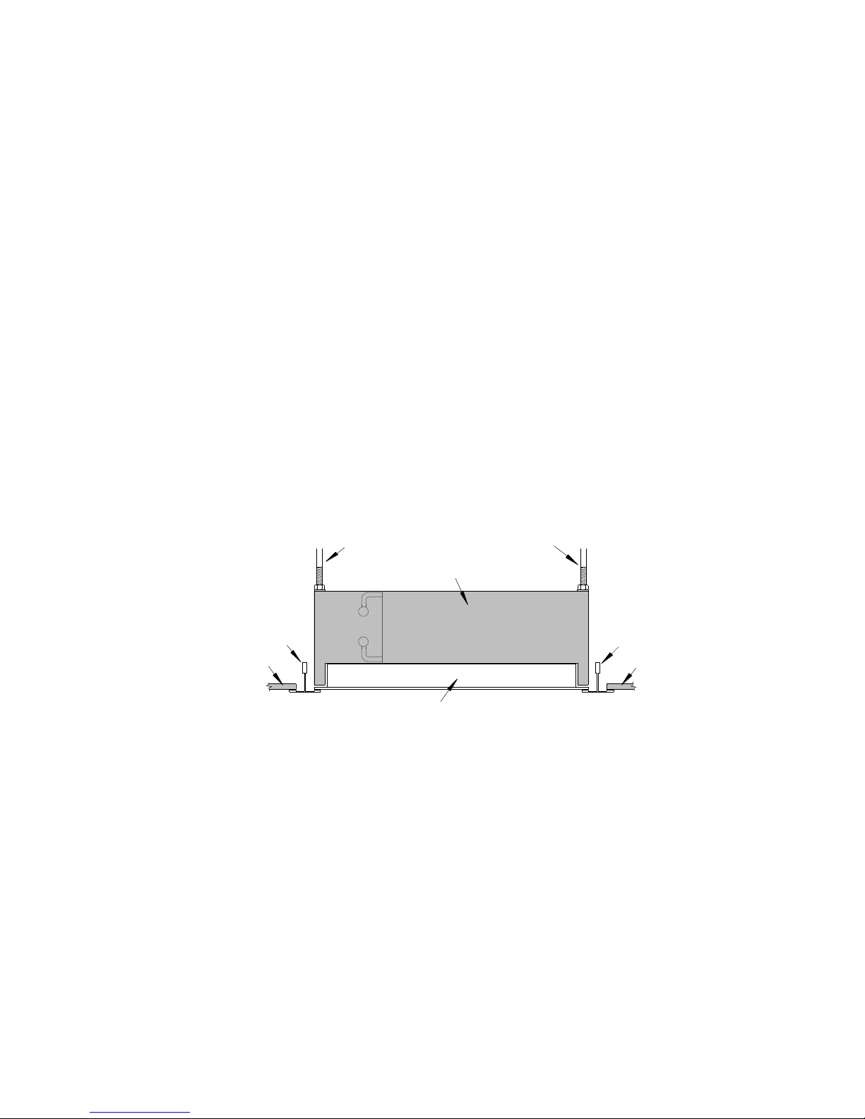
Page 4

HEATER UNIT
ADJUSTABLE BRACKETS
T-BAR
HANGING
BOLT
HANGING
BOLT
TILE
T-BAR
TILE
PUNCHED GRILLE
GRILLE FIXINGS
500 HANGING CTRS
563
570 HANGING CTRS
595
595
595
538
538
204
50
55
255
195
45
55
100
Control Panel
Fan Inlet
Heat Outlet
Heat Exchanger
DRILL 2 HOLES EACH SIDE THROUGH
GRILLE AND HEATER UNIT SIDES AND
SCREW IN PLACE
L.T.C
FAN
135V 155V 175V
SWITCH
CAPACITOR
TRANSFORMER
N
L
N
L
E
SUPPLY
L L
7
8
N N
9
E
E
N
E
L
Installation into a plasterboard ceiling
Figure 3
Note: Access to the ceiling void, other than the heater cut-out must be available for
installation for plumbing, electrical connection and maintenance.
1) Cut a square hole 575mm x 575mm into the plasterboard and ensure that any obstructions
are a minimum of 210mm away from the heater.
2) Ensure suitable means of support such as threaded rods or chains are used and fixed into
place directly above the chosen installation cut-out.
3) Lift the heater through the cut-out into the void and securely attach the supports to the
heater.
4) Lift the grille into the cut-out and adjust the heater so that they meet together.
5) Drill four holes 3mm (1/8”) holes (two in each side) and secure with the provided screws
(see figure 4). Once secured the grille can be open and closed by pushing against the
grille on the side with the closure (Once to open, Once again to close), care should be
taken not to bend the grille.
6) Proceed to page 5 for plumbing and electrical connection.
Proceed to page 5 for plumbing and electrical connection
Figure 4
4
Plumbing connection
Pipe connections to the heat exchanger should be made using 22mm pipe and fittings, Isolating
valves should be fitted to ensure the product is serviceable in the future. It is advisable to use
flexible hoses to reduce vibration (available as an accessory, see page 7). An air vent must also be
fitted to the system pipework above the highest point of the product.
Pipe entry should be made through the entry holes in the end of the heater (shown in fig 1).
Isolating/ Service valves may be installed within the heater casing, a removable panel in the side of
the heater allows valves to be adjusted however additional access to the void space must be
available (in a T-Bar ceiling an adjacent removable tile would suffice however in plasterboard celling
access would have to be considered before installation).
Figure 5
Electrical connection
Unscrew and remove the electrical panel, connect the fused spur to the terminal block in the unit
using suitable 3 core cable (see wiring diagram below).
Figure 6
Page 5

500 HANGING CTRS
563
570 HANGING CTRS
595
595
595
538
538
204
50
55
255
195
45
55
100
Control Panel
Fan Inlet
Heat Outlet
Heat Exchanger
L.T.C
FAN
135V 155V 175V
SWITCH
CAPACITOR
TRANSFORMER
N
L
N
L
E
SUPPLY
L L
7
8
N N
9
E
E
N
E
L
Plumbing connection
Pipe connections to the heat exchanger should be made using 22mm pipe and fittings, Isolating
valves should be fitted to ensure the product is serviceable in the future. It is advisable to use
flexible hoses to reduce vibration (available as an accessory, see page 7). An air vent must also be
fitted to the system pipework above the highest point of the product.
Pipe entry should be made through the entry holes in the end of the heater (shown in fig 1).
Isolating/ Service valves may be installed within the heater casing, a removable panel in the side of
the heater allows valves to be adjusted however additional access to the void space must be
available (in a T-Bar ceiling an adjacent removable tile would suffice however in plasterboard celling
access would have to be considered before installation).
Figure 5
Electrical connection
Unscrew and remove the electrical panel, connect the fused spur to the terminal block in the unit
using suitable 3 core cable (see wiring diagram below).
Figure 6
5
Page 6

HEATER UNIT
GRILLE
T-BAR
HANGING
BOLT
HANGING
BOLT
TILE
T-BAR
TILE
Commissioning
Ensure the central heating system is ON. Providing the water temperature in the central heating
system is more than 35°C and the thermostat (if fitted) is calling for heat the product will switch on.
1) Turn on the electrical supply to the unit at the fused spur.
2) Turn on the heating system.
3) Turn the thermostat control (if fitted) to the maximum.
4) If the heater is installed on the same circuit as panel radiators balance the central heating
system.
5) Adjust the fan speed by changing the switch position to the preferred
6) If the installation is working correctly remember to reset the thermostat control (if fitted) to its
normal setting.
If your heater does not operate refer to “Fault Finding” on page 7.
Maintenance
Warning! Isolate from the electrical supply before servicing.
The heater is fitted with a replaceable air filter. To remove the filter lower the hinged grille, loosen
the two screws securing the filter retainer (See Figure 1), slide the across to give access and
remove the filter, replacing the air filter is the reverse of removing it. The filter can be gently tapped
or vacuumed to remove any accumulated dust. Replacement filters should be fitted as part of
regular and routine maintenance.
The filter is not covered by Smith’s 5 Year Guarantee.
The heat exchanger should be cleaned with a soft brush or vacuum to remove any dust that may
have accumulated, care must be taken not to damage the delicate heat exchanger fins.
The fan(s) and motors should not require servicing. Please contact your supplier if damaged.
Please note in the event of an engineer’s visit, Smith’s Environmental Products Ltd reserve the
rights to apply a call-out charge should the fault prove to be with the system or installation and not
the heater appliance.
6
Preparation
The following items should be included in the carton:
Caspian Skyline
Grille.
X4 M5 Screws.
Other items (Not included) required for a successful installation:
Three core mains cable.
Isolating valves (Failure to fit isolating valves may mean that the product is not serviceable
Air Vent/ Bleed valve.
Suitable mounting hardware (Such as chains, threaded rod etc).
Accessories including replacement air filters are available (See page 7).
In the event of any items missing or visible damage, please contact us on 01245 324560,
Installation
This heater should be mounted at a minimum height of 1.8m (To the underside of the grille) and a
maximum height 4m
Installation into a suspended T Bar ceiling
Figure 3
1) Choose the position in the ceiling grid that the heater is to be installed and remove the
2) Ensure suitable means of support such as threaded rods or chains are used and fixed into
3) Lift the heater through the T bar grid into the void and securely attach the supports to the
4) Level the adjustable brackets (See figures 3 and 4.) with the finished ceiling and tighten
5) Lift the grille to the heater so that the holes in the grille align with the fixing holes in the
6) Fix the grille to the heater using the supplied screws
7) Proceed to page 5 for plumbing and electrical connection.
Page 7

Fault Finding
1) The fan does not run on any switch setting.
a) Check the power supply is switched ON.
b) Check the fuse in the fused spur.
c) Check the wiring at the fused spur.
2) No heat output.
a) Vent any trapped air from the system (with the heating system turned OFF).
b) Check the central heating is switched ON.
c) If a thermostat is fitted ensure it is calling for heat.
d) Balance the central heating system if installed on the same circuit as panel radiators and
increase the circulating pump speed if required.
e) Increase the boiler water temperature.
In the event of difficulty please contact our technical help-line on 01245 324560. It will be helpful if
you do not disconnect the heater from the central heating system.
Information and advice
A product brochure containing full technical specifications and list prices is available to
download from our website or in hard copy from our office. Also available on our website are
price lists, individual product datasheets, installation & user guides, where to buy, who to
contact and a media centre.
Alternatively contact our office 9.00am to 5.00pm Monday to Thursday, 9.00am to 4.00pm to
Friday.
7
Optional Accessories
Optional accessories are available to offer additional control or functionally not offered by the heater
in its standard configuration.
Electrical Accessories
Wall Switch Kit CT60AC WSC
Allows an on/off wall switch to be mounted on the wall to control heater.
Suitable cable to connect the switch from the heater to the switch is not supplied.
Adjustable low temperature cut-out CT60 ALTC T3
This enables the end user to precisely select the temperature at which the fans will switch on when
combined with different heat sources.
Miscellaneous Accessories
Caspian 22mm Flexible Hoses CAS22FH
Replacement air filters
For accessories or spares please contact either your supplier or Smith’s Environmental
Products Ltd.
Page 8

Guarantee Statement
Thank you for purchasing a Smith’s heater.
It has been designed and manufactured to the highest quality standards to ensure it
gives you efficient and trouble-free service for many years.
To back up our commitment, included with your product is a free five year parts
and labour guarantee (excludes filters if fitted).
This gives you peace of mind that in the unlikely event of the product failing within
the first five years, we will repair or replace the product completely free of charge
provided the product has been installed, used and maintained in accordance with the
instructions.
It is important to register within 7 days. This will ensure you receive a prompt and
efficient service, if your product requires attention within the guarantee period. If
you do not register your product, you will be required to produce a proof of purchase
prior to receiving this service.
If you experience any problems with the use of your product, please contact our
after-sales office on 01245 324560.
Smith’s Environmental Products Ltd manufactures a complete range of heaters for
domestic and commercial applications.
If you require any further information, please contact us on 01245 324900 or visit
our website at www.SmithsEP.co.uk
Your statutory rights are not affected by this guarantee.
Please pull this Registration card from the
booklet and fill in all parts and return.
Page 9

Guarantee Registration Card
& Customer Satisfaction Survey
Dear Customer
We hope our product suits all your requirements; it would help us immensely if you could find the time to
fill in this form, your response will help us maintain the quality standards we all expect in today’s climate.
Customer name ________________________________________ Date_____/_____/__________
Email Address ____________________________@________________________________________
Product Name ______________________________________________________________________
Tick as appropriate
V Good Good Fair Poor
Product
Delivery
Sales & Ordering
Response to
any problems
Comments …………………………………………………………………………………………………
………………………………………………………………………………………………..
………………………………………………………………………………………………..
Thank you for your time to fill in this survey, the response will help us to serve your
needs more effectively. Please return by fax to 01245324422.
Quality Control Manager: Ron Brown ron.brown@smithsep.co.uk
User Details
User Name Mr/Mrs/Miss/Ms/Other ……………………………………………………………………………
Initials …………………. Surname ………………………………………………………………………………
Address ………………………………………………………………………………………………………………….
………………………………………………………………………………………………………………………………
…………………………………………………………………… Post Code: …………………………………
Telephone: ……………………………………………………………………………………………………………..
Product & Model installed (e.g. Space Saver SS5)
……………………………………………………………………………………………………………………………….
Room Installed (e.g. Kitchen): …………………………………………………………………………………..
Your details will only be held by Smiths Environmental Products Ltd and used solely to
provide customer services and product information.
If you do not wish to be contacted, please put an x in the box.
Installer Details
Company name: …………………..
Principal contact: Mr/Mrs/Miss/Ms/Other: …………………………………………………………………
Initials: ………………… Surname: ……………………………………………………………………………
Address: …………………………………………………………………………………………………………………
………………………………………………………………………………………………………………………………
…………………………………………………………………… Post Code: ……………………………………
Telephone: …………………………………………………………………………………………………………….
Date of installation ……………/……………/………………
Room Installed (e.g. Kitchen): …………………………………………………………………………………..
Your details will only be held by Smiths Environmental Products Ltd and used solely to
provide customer services and product information.
If you do not wish to be contacted, please put an x in the box.
Page 10

Accessories
For a full list of optional extras and accessories for you product please see Page 7.
To order accessories or spares please contact either your supplier
or Smith’s Environmental Products Ltd.
Technical designation: Caspian Skyline
®
CT60 AC
Products with this symbol (crossed out wheelie bin) cannot be disposed as household waste.
Old electrical and electronic equipment must be recycled at a facility capable of handling these
products and their waste by-products. If you are purchasing replacement equipment your
retailer may offer a 'take back' scheme, or will be able to give details of the nearest approved
authorised treatment facility. Proper recycling and waste disposal will help conserve resources
whilst preventing detrimental effects on our health and the environment.
WEEE Registered Code : WEE/ED0093VW
In the event of any items missing or visible damage, please contact us on 01245 324560.
For Ireland (Republic & Northern), contact MT Agencies on 00 353 1 864 3363
In light of our policy of continuous development Smith’s Environmental Products Ltd
reserve the right to alter specifications without prior notice.
Issue: 6 8 Oct 018
User Information:
This appliance can be used by children aged from 8 years and above and
persons with reduced physical, sensory or mental capabilities or lack of
experience and knowledge if they have been given supervision or
instruction concerning use of the appliance in a safe way and understand
the hazards involved. Children shall not play with the appliance. Cleaning
and user maintenance shall not be made by children without supervision
A means for disconnection from the supply mains having a contact
separation in all poles that provides full disconnection under overvoltage
category III conditions must be incorporated in the fixed wiring in
accordance with the wiring rules.
Ensure that the fan convector is switched-off before opening the cover.
CASPIAN SKYLINE®
CT60 AC
Ceiling Level Fan Convector
Smith’s Environmental Products Ltd
Blackall Industrial Estate, South Woodham Ferrers, Chelmsford, Essex, CM3 5UW
Tel: 01245 324900 Fax: 01245 324422
Sales: sales@SmithsEP.co.uk General Information E-mail: info@SmithsEP.co.uk Web: www.SmithsEP.co.uk
 Loading...