

Page 1
T
E
C
H
N
L
A
U
N
A
M
L
A
C
I
™
y
S
P
M
U
P
N
C
A
A
M
B
D
U
L
D
A
T
O
-
R
L
Y
e
I
N
g
F
U
a
I
S
c
O
44
CADD-Legacy™ 1 Pump
CADD-Legacy
CADD-Legacy
™
PCA Pump
™
PLUS Pump
Deltec
Page 2

For detailed instructions, specifications, warnings, warranties, and additional information on operating CADD
additional comments or questions concerning the operation of CADD
®
pumps, please refer to the Operator’s Manual supplied with the product. If you have
®
pumps, please call this number: 800-426-2448. Our staff is available to help you twenty-four hours a day with the programming
and operation of CADD® pump infusion systems.
The issue date of this Technical Manual is included on the back cover for the user’s information. In
the event one year has elapsed between the issue date and product use, the user should contact
SIMS Deltec, Inc. to see if a later revision of this manual is available.
Issue Date: January 2000
41
Page 3

Table of Contents
1. Introduction ............................................. 1
Limited Warranty .......................................... 1
Exposing CADD® Pumps to Radiation, Ultrasound, or MRI or use near ECG equipment ... 1
2. CADD-Legacy™ Pump
Delivery Modes .............................................. 2
Specifications (Nominal) ................................ 5
Compatible Medication Cassette™ Reservoirs
and CADD
Remote Dose Cord ......................................... 7
®
Administration Sets ................... 7
3. Batteries ................................................... 8
Battery Compatibility ..................................... 8
DURACELL® Alkaline Battery Life............... 8
4. Construction .......................................... 11
5. Theory of Operation .............................. 12
Keyboard Circuitry ...................................... 12
Data Memory in Real Time Clock RAM ...... 12
EEPROM .................................................... 12
Battery Backed RAM ................................... 12
Time Base Circuitry ..................................... 12
LCD Circuitry .............................................. 12
LED Indicator ............................................. 13
Flash PROM Technology ............................. 13
Audible Alarm Circuitry ............................... 13
Watchdog Timer Circuit .............................. 13
Motor Drive/Motor Watchdog Circuit ......... 13
Power Circuitry ............................................ 14
Voltage Reference Circuit ............................. 14
Pumping Mechanism .................................... 14
Pumping Characteristics ............................... 15
Air Detector ................................................. 15
Downstream Occlusion Sensor .................... 16
Upstream Occlusion Sensor ......................... 16
Cassette Attachment Detection..................... 16
6. Safety Features and Fault Detection ....... 17
Hardware Safety Features ............................ 17
Software Safety Features .............................. 19
7. Hardware and Software Fault Detection 20
Overview ..................................................... 20
Order of Error Code Events ......................... 20
8. Cleaning and Inspection Procedures ....... 21
Inspection Recommendation ........................ 21
Cleaning ....................................................... 21
Battery Contact Cleaning ............................. 21
Visual Inspection .......................................... 22
Mechanical Inspection .................................. 22
9. Testing Procedures ................................. 23
Testing Recommendation ............................. 23
Changing to Lock Level 0 (LL0) .................. 23
CADD-Legacy™ PCA pump ................... 23
Air Detector Test ...................................... 25
Upstream Occlusion Sensor Test ............... 25
Occlusion Pressure Range Tests ................ 25
Accuracy Testing ....................................... 27
CADD-Legacy™ 1 pump ........................ 29
Air Detector Test ...................................... 30
Upstream Occlusion Sensor Test ............... 30
Occlusion Pressure Range Tests ................ 31
Accuracy Testing ....................................... 32
CADD-Legacy™ PLUS pump .................. 34
Air Detector Test ...................................... 35
Upstream Occlusion Sensor Test ............... 36
Occlusion Pressure Range Tests ................ 36
Accuracy Testing ....................................... 37
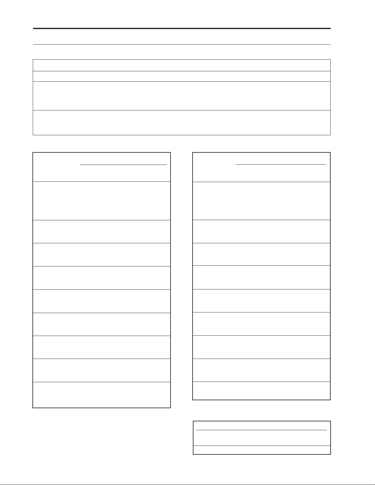
Cleaning and Functional Testing
Checklist ................................................ 40
42
Page 4

1 Introduction
This Technical Manual is intended to provide
an understanding of the mechanical and electrical operation of the CADD-Legacy
™
CADD-Legacy
1, and CADD-Legacy™ PLUS
Computerized Ambulatory Drug Delivery
pumps to persons familiar with these devices.
The CADD-Legacy
and CADD-Legacy
™
PCA, CADD-Legacy™ 1,
™
PLUS pump Operator’s
Manuals should be used in conjunction with
this publication for complete information.
This manual also outlines cleaning and functional testing procedures that can be performed
on the CADD-Legacy
and CADD-Legacy
™
PCA, CADD-Legacy™ 1,
™
PLUS pumps.
WARNING:
This Technical Manual must be used by Biomedical Technicians only. Do not permit patients
to have access to this manual. Do not disclose to
the patient the pump’s security codes or any other
infomation that would allow the patient complete
access to all programming and operating
functions. Improper programming could result in
death or serious injury to the patient.
IMPORTANT NOTICE:
CADD-Legacy
CADD-Legacy
™
PCA, CADD-Legacy™ 1, and
™
PLUS pump operations and
safety features are based on a microcomputer
design. Inadequate servicing or tampering with
the safety features of the pumps may seriously
affect performance and safety.
For that reason, ALL SERVICING AND
REPAIR OF THE CADD-Legacy
MUST BE PERFORMED BY DELTEC OR ITS
AUTHORIZED AGENTS.
The manufacturer’s warranty agreement shall
become null and void if the pump is not used in
accordance with the Operator’s Manual and
Instructions for Use for the pump accessories;
or, the pump is serviced by persons other than
Deltec or those authorized by Deltec.
Limited Warranty
The limited warranty associated with the
CADD-Legacy
CADD-Legacy
the product literature supplied with the product
when originally purchased, which is incorporated herein by reference. DELTEC SPECIFI-
™
PCA, CADD-Legacy™ 1, and
™
PLUS pumps can be found in
™
™
PUMPS
PCA,
CALLY DISCLAIMS ANY OTHER WARRANTY, WHETHER EXPRESS, IMPLIED OR
STATUTORY, INCLUDING, WITHOUT
LIMITATION, ANY IMPLIED WARRANTY
OF MERCHANTABILITY OR FITNESS FOR
USE. Deltec further disclaims responsibility for
the suitability of the system for a particular
medical treatment or for any medical complications resulting from the use of the system. The
manufacturer shall not be responsible for any
incidental damages or consequential damages to
property, loss of profits, or loss of use caused by
any defect or malfunction of the system.
If you wish to receive additional information
about the extent of the warranty on these products, please contact your Deltec representative or
call Customer Service at 1-800-426-2448.
All recommendations, information, and literature supplied by Deltec with respect to the
CADD
®
product line are believed to be accurate
and reliable, but do not constitute warranties.
No agent, representative, or employee of Deltec
has authority to bind Deltec to any representation or warranty, expressed or implied.
Exposure to Radiation, Ultrasound or
Magnetic Resonance Imaging (MRI),
or use near ECG equipment
CAUTION:
• Do not expose the pump to therapeutic levels of
ionizing radiation as permanent damage to the
pump’s electronic circuitry may occur. The best
procedure to follow is to remove the pump
from the patient during therapeutic radiation
sessions. If the pump must remain in the vicinity
during a therapy session, it should be shielded,
and its ability to function properly should be
confirmed following treatment.
• Do not expose the pump directly to ultrasound,
as permanent damage to the pump’s electronic
circuitry may occur.
• Do not use the pump in the vicinity of magnetic
resonance imaging (MRI) equipment as magnetic fields may adversely affect the operation
of the pump. Remove the pump from the patient during MRI procedures and keep it at a
safe distance from magnetic energy.
• Do not use the pump near ECG equipment as
the pump may interfere with the operation of
the equipment. Monitor ECG equipment carefully when using this pump.
1
Page 5
2 CADD-Legacy™ Pump
Delivery Modes
The CADD-Legacy™ ambulatory drug delivery
pump provides measured drug therapy to
patients in hospital or outpatient settings. The
CADD-Legacy
nous, intra-arterial, subcutaneous, intraperitoneal, epidural space, or subarachnoid space
infusion.
Epidural administration is limited to use with
indwelling catheters for short term delivery of
anesthetics and short or long term delivery of
analgesics. Subarachnoid administration is
limited to use with indwelling catheters for
short-term delivery of analgesics.
(used here as a loading dose)
Dosage
™
pump is indicated for intrave-
Clinician Bolus
Demand Doses
Continuous Rate
The CADD-Legacy
™
PCA pump may be
programmed to deliver medication in one of
three ways: 1) continuous rate only, 2) patientactivated dose only and 3) continuous rate and
patient-activated dose. (See figure 1.)
The CADD-Legacy
™
PLUS pump may be
programmed to deliver in one of two modes:
(1) Continuous, (2) Intermittent . (See figures 2
and 3.)
The CADD-Legacy
™
1 pump operates in
continuous mode. (See figure 2.)
Figure 4 shows a diagram of the CADDLegacy
™
pump.
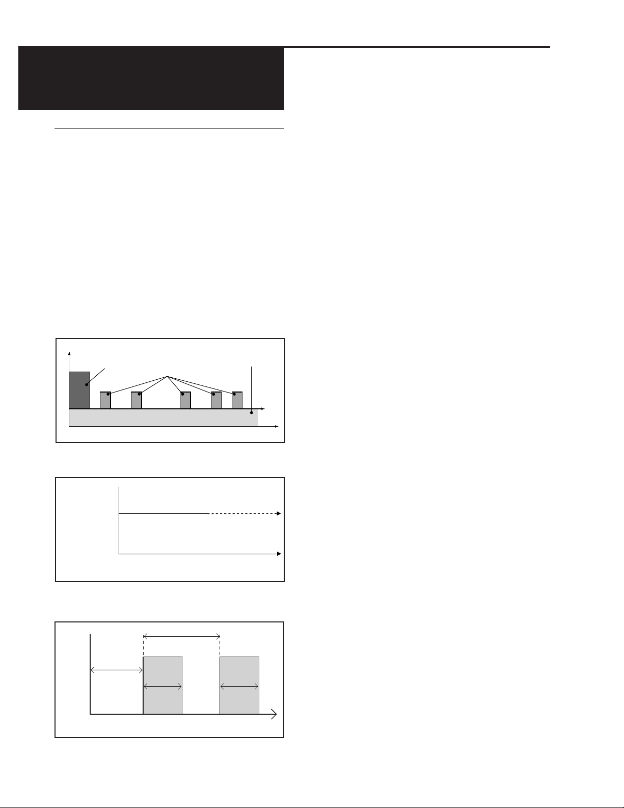
PCA Delivery Profile
The PCA (patient-controlled analgesia) delivery
mode is used for therapies that require a
continuous rate of infusion, patient-controlled
demand doses, or both, such as patientcontrolled analgesia.
Time
Figure 1. PCA mode delivery profile.
Delivery
Rate
CADD-Legacy™ PLUS
(ML/HR)
or
CADD-Legacy™ 1
(ML/24 HR)
Time
Continuous Delivery
Figure 2. Continuous mode delivery profile.
Dose Cycle
Dose
Volume
Dose
Starts
in
Dose
Duration
Time
Intermittent Delivery
Dose
Duration
Continuous Mode Delivery Profile
The Continuous delivery mode allows the
infusion of drug at a constant, programmed
rate.
Intermittent Mode Delivery Profile
The Intermittent delivery mode allows the
infusion of a specific volume of drug at regular
programmed intervals.
Figure 3. Intermittent mode delivery profile.
2
Page 6
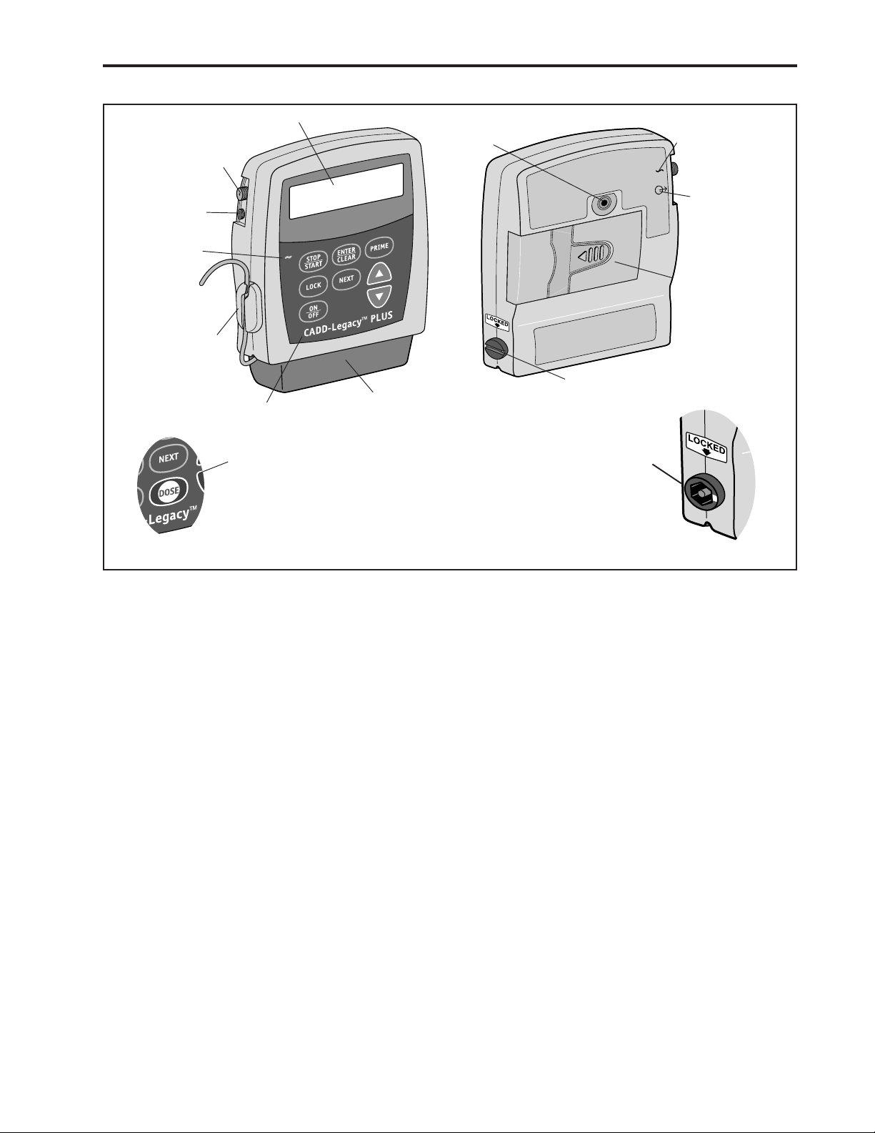
Power Jack
Display
Threaded
Mounting
Hole
Power Jack
symbol
Accessory
Jack
AC Indicator
Light
Air Detector
®
Cassette Lock
Keypad
Dose Key on
CADD-Legacy™ PCA
Front View
Figure 4. Front and Rear views of the CADD-Legacy™ Pump. Features are identical on all CADD-Legacy™ pumps except as
illustrated for the CADD-Legacy™ PCA pump.
Cassette
CADD-Legacy™ PCA
Cassette Lock
Rear View
Accessory
Jack Symbol
Battery
Compartment
3
Page 7
PCA Delivery Mode Scroll Ranges
Units
ML
MG
MCG
Starting
0.10
10% of
Concentration
10% of
Concentration
Increment
All values:
Values between 0.01 and 0.5:
Values between 0.50 and 100.0:
Values between 100.0 and 1000.0:
Values greater than 1000.0:
Values between 0.1 and 100:
Values between 100 and 1000:
Values greater than 1000:
Table 1. PCA delivery mode: continuous rate scroll ranges.
Milligrams
Concentration Demand Dose Clinician Bolus
mg/ml increment max. increment max.
0.1 0.01 0.99 0.01 2
0.2 0.02 1.98 0.02 4
0.3 0.03 2.97 0.03 6
0.4 0.04 3.96 0.04 8
0.5 0.05 4.95 0.05 10
1 0.05 9.9 0.05 20
2 0.10 19.8 0.10 40
3 0.15 29.7 0.15 60
4 0.20 39.6 0.20 80
5 0.25 49.5 0.25 100
10 0.50 99.0 0.50 200
15 0.75 148.5 0.75 300
20 1.00 198.0 1.00 400
25 1.25 247.5 1.25 500
30 1.50 297.0 1.50 600
35 1.75 346.5 1.75 700
40 2.00 396.0 2.00 800
45 2.25 445.5 2.25 900
50 2.50 495.0 2.50 1000
55 2.75 544.5 2.75 1100
60 3.00 594.0 3.00 1200
65 3.25 643.5 3.25 1300
70 3.50 693.0 3.50 1400
75 3.75 742.5 3.75 1500
80 4.00 792.0 4.00 1600
85 4.25 841.5 4.25 1700
90 4.50 891.0 4.50 1800
95 4.75 940.5 4.75 1900
100 5.00 990.0 5.00 2000
Table 2. Demand dose, clinician bolus scroll ranges,
milligrams
4
Maximum
0.10
0.01
0.10
1.00
10.0
0.10
1.00
10.00
50.00
Concentration
x 50
Concentration
x 50
Micrograms
Concentration Demand Dose Clinician Bolus
mcg/ml increment max. increment max.
1 0.05 9.9 0.05 20
2 0.10 19.8 0.10 40
3 0.15 29.7 0.15 60
4 0.20 39.6 0.20 80
5 0.25 49.5 0.25 100
10 0.50 99.0 0.50 200
15 0.75 148.5 0.75 300
20 1.00 198.0 1.00 400
25 1.25 247.5 1.25 500
30 1.50 297.0 1.50 600
35 1.75 346.5 1.75 700
40 2.00 396.0 2.00 800
45 2.25 445.5 2.25 900
50 2.50 495.0 2.50 1000
55 2.75 544.5 2.75 1100
60 3.00 594.0 3.00 1200
65 3.25 643.5 3.25 1300
70 3.50 693.0 3.50 1400
75 3.75 742.5 3.75 1500
80 4.00 792.0 4.00 1600
85 4.25 841.5 4.25 1700
90 4.50 891.0 4.50 1800
95 4.75 940.5 4.75 1900
100 5.00 990.0 5.00 2000
200 10.00 1980.0 10.00 4000
300 15.00 2970.0 15.00 6000
400 20.00 3960.0 20.00 8000
500 25.00 4950.0 25.00 10000
Table 3. Demand dose, clinician bolus scroll ranges,
micrograms
Milliliters
Demand Dose Clinician Bolus
increment max. increment max.
0.05 9.9 0.05 20
Table 4. Demand dose, clinician bolus scroll ranges,
milliliters
Page 8

Specifications (Nominal)
High Pressure Alarm
26 (±14) psi, 1.79 (± 0.97) bar
General Pump Specifications
Resolution
Medication Cassette
Administration Set, 0.050 ml/pump stroke
nominal
Size
4.1 cm x 9.5 cm x 11.2 cm (1.6 in. x
3.8 in. x 4.4 in.) excluding cassette or other
accessories
Weight
391 g (13.8 oz.) including 2 AA batteries,
empty 100-ml Medication Cassette
Reservoir, and air detector, excluding other
accessories
Pump Alarms
Low battery power; depleted battery
power; battery dislodged; pump stopped;
pump fault; low reservoir volume; high
delivery pressure; air in line; disposable not
attached when run attempted; motor
locked; upstream occlusion; reservoir
volume empty; program incomplete;
remote dose cord removed; key stuck;
disposable detached, power removed, value
not saved.
Bolus Volume at Occlusion Alarm Pressure
0.050 ml resolution sets/reservoirs:
< 0.15 ml
Power Sources
Two AA alkaline batteries such as DURA-
®
CELL
or EVEREADY Energizer®; AC
adapter.
An internal battery powers the clock.
When it is depleted, it cannot reliably
maintain the clock time. This battery must
be replaced by SIMS Deltec, Inc. The
internal battery has an expected life of 5
years.
System Operating Temperature*
+2°C to 40°C (35°F to 104°F)
System Storage Temperature*
-20°C to 60°C (-4°F to 140°F)
System Delivery Accuracy*
± 6% (nominal)
™
Reservoir or CADD
™
Air Detector Alarm
Single bubble
®
Low sensitivity = greater than 0.250 ml
High sensitivity = greater than 0.100 ml
Multi-bubble = 1.0 ml nominal
Delivery Mode Specifications
CADD-Legacy™ PCA pump
Reservoir Volume
1 to 9999 or Not In Use; programmable in
1 ml increments, displayed in 0.1 ml
increments
Default: 1 ml
Units
Milliliters (ml), milligrams (mg), micrograms (mcg)
Default: milligrams
Concentration
Mg/ml: 0.1, 0.2, 0.3, 0.4, 0.5, 1, 2, 3, 4, 5,
10, 15, ... 95, 100 (Default: 100 mg/ml)
Mcg/ml: 1, 2, 3, 4, 5, 10, 15, ...95, 100,
200, 300, 400, 500 (Default: 500 mcg/ml)
Continuous Rate
0 to 50 ml/hr (or the mg or mcg equivalent)
(See Table 1 for scroll ranges)
Demand Dose
0 to 9.9 ml in 0.05 ml increments (or the
mg or mcg equivalent)
(See Tables 2 and 3 for scroll ranges)
Delivery rate (Continuous Rate + Demand
Dose): 125 ml/hr nominal
Dose Lockout
5 minutes to 24 hours in the following
increments:
1 minute for values between 5 and 20
minutes
5 minutes between 20 minutes and 24
hours
Default: 24 hours
Doses Per Hour
1 to 12 doses in 1 dose increments (will
also be limited by the Demand Dose
Lockout value)
Default: 1 dose/hr
*System is defined as a CADD-Legacy™ pump with an attached Medication Cassette™ Reservoir and CADD® Extension Set with
integral anti-siphon valve, or an attached CADD® Administration Set with integral or add-on anti-siphon valve.
5
Page 9

Doses Given
0 to 999
5 minutes from 00:10 to 24:00
Default: 30 minutes
Doses Attempted
0 to 999
Given
0 to 99999.95 in 0.05 unit increments or
0 to 99999.99 in 0.01 unit increments
(increments converted to current units
based on concentration)
Clinician Bolus
0.05 ml to 20.00 ml (or mg or mcg equivalent) (See Tables 1, 2 and 3 for scroll
ranges)
Delivery rate (Continuous Rate + Clinician
Bolus): 125 ml/hr nominal
™
CADD-Legacy
1 pump
Continuous Delivery Mode Specifications
Reservoir Volume
1 to 9999 or Not In Use; programmable in
1 ml increments, displayed in 0.1 ml
increments
Default: 1 ml
Continuous Rate
1 to 3000 ml/24 hr in increments of
1 ml/24hr
Default: 0 ml/24hr
Given
0 to 99999.95 in 0.05 ml increments
Dose Cycle
10 minutes to 96 hours in 5 minute increments
Default: 4 hours
KVO Rate
0 to 125.0 ml/hr in increments of 0.1 ml/hr
Default: 0 ml/hr
Dose Starts in
Immediate or 1 minute to 96 hours in the
following increments:
00:01 from 00:00 to 00:10
00:05 from 00:10 to 96:00
Default: Immediate
Continuous Delivery Mode Specifications
Reservoir Volume
1 to 9999 or Not In Use; programmable in
1 ml increments, displayed in 0.1 ml
increments
Default: 1 ml
Continuous Rate
0.1 ml/hr to 125.0 ml/hr in increments of
0.1 ml/hr
Default: 0.0 ml/hr
Given
0 to 99999.95 in 0.05 ml increments
Biomed Functions Specifications
CADD-Legacy
™
PLUS pump
Intermittent Delivery Mode Specifications
Reservoir Volume
1 to 9999 or Not In Use; programmable in
1 ml increments, displayed in 0.1 ml
increments
Default: 1 ml
Dose Volume
0.1 to 1000.0 ml in increments of 0.1
Default: 0.0 ml
Dose Duration
1 minute to 24 hours in the following
increments:
1 minute from 00:01 to 00:10
6
Air Detector Status:
Off
On- low
On- high
Default: On-high
Upstream Occlusion Status:
Off
On
Default: On
Delivery Mode (CADD-Legacy
Continuous
Intermittent
Default: Intermittent
™
PLUS only):
Page 10

Compatible Medication Cassette
™
Reservoirs and CADD® Administration
Sets
• 50-ml or 100-ml Medication Cassette
Reservoir, used with the CADD® Extension
Set with Anti-siphon Valve.
• CADD
®
Administration Set with integral
anti-siphon valve, with or without bag spike
(allows use of flexible plastic bag or sterile
vial with injector)
• CADD
®
Administration Set with add-on
anti-siphon valve and bag spike (allows for
gravity priming before attaching the add on
anti-siphon valve)
™
Remote Dose Cord
Deltec provides a Remote Dose Cord for the
CADD-Legacy
sion of the
Single Pole Double Throw (SPDT) switch
which operates in the same manner as the
key. When the Remote Dose Cord is attached
to the pump, the patient may press either the
Remote Dose button or the
a Demand Dose. The clinician may also use
either the Remote Dose button or the
to deliver a clinician-activated bolus. For easy
access, the Remote Dose Cord may be fastened
to the patient’s clothing or bedsheet with the
attached clip.
There is an alarm/function present in the
CADD-Legacy
Dose Cord is removed, the display shows a
message “Remote Dose Removed”. The pump
sounds an audible alarm until the
pressed to acknowledge the alarm.
™
PCA pump which is an exten-
Í key. The push button is a
Í key to receive
Í key
™
PCA pump. If the Remote
„ key is
Í
NOTE:
To detach the Remote Dose Cord from the
pump, grasp the Remote Dose Cord
connector and pull back using a straight,
steady motion.
7
Page 11

3 Batteries
Battery Compatibility
Recommended Batteries
Two AA alkaline batteries are recommended
for use in the CADD-Legacy
™
pumps. Carbonzinc, mercury, nickel-cadmium, nickel-metalhydride, or zinc-air AA batteries should not be
used.
Battery Life
The CADD-Legacy
™
pumps have been designed to provide optimal battery life. The
expected battery life in the CADD-Legacy
™
pumps depends on the following factors:
• Programmed delivery rate
• Operating temperatures
• Battery type and brand
• Battery age
DURACELL® Alkaline Battery Life
Recommended storage conditions are 10°C to
25°C (50°F to 77°F) with no more than 65%
relative humidity noncondensing.
The following table may be used to predict
typical alkaline battery life at different delivery
rates when alkaline batteries are used in the
™
CADD-Legacy
pump. As expected, battery
life decreases as the delivery rate increases.
This table is based on laboratory tests using
fresh DURACELL
CADD-Legacy
®
alkaline batteries in
™
pumps while the pumps were
operating at room temperature.
Actual battery life may be significantly shorter
depending on the operating temperature and
the storage conditions of the battery.
Battery life is shortened significantly at very
low operating temperatures. For example, at
0°C (32°F), an alkaline battery will yield
approximately 30% of its normal capacity.
Alkaline batteries do not need to be stored in a
refrigerator. After four years of storage at 21°C
(70°F), an alkaline battery retains approximately 86% of its original capacity. Battery life
will be shorter if the battery is stored above
room temperature. An alkaline battery stored
at 43°C (110°F) will be down to approximately
80% of its capacity within one year.
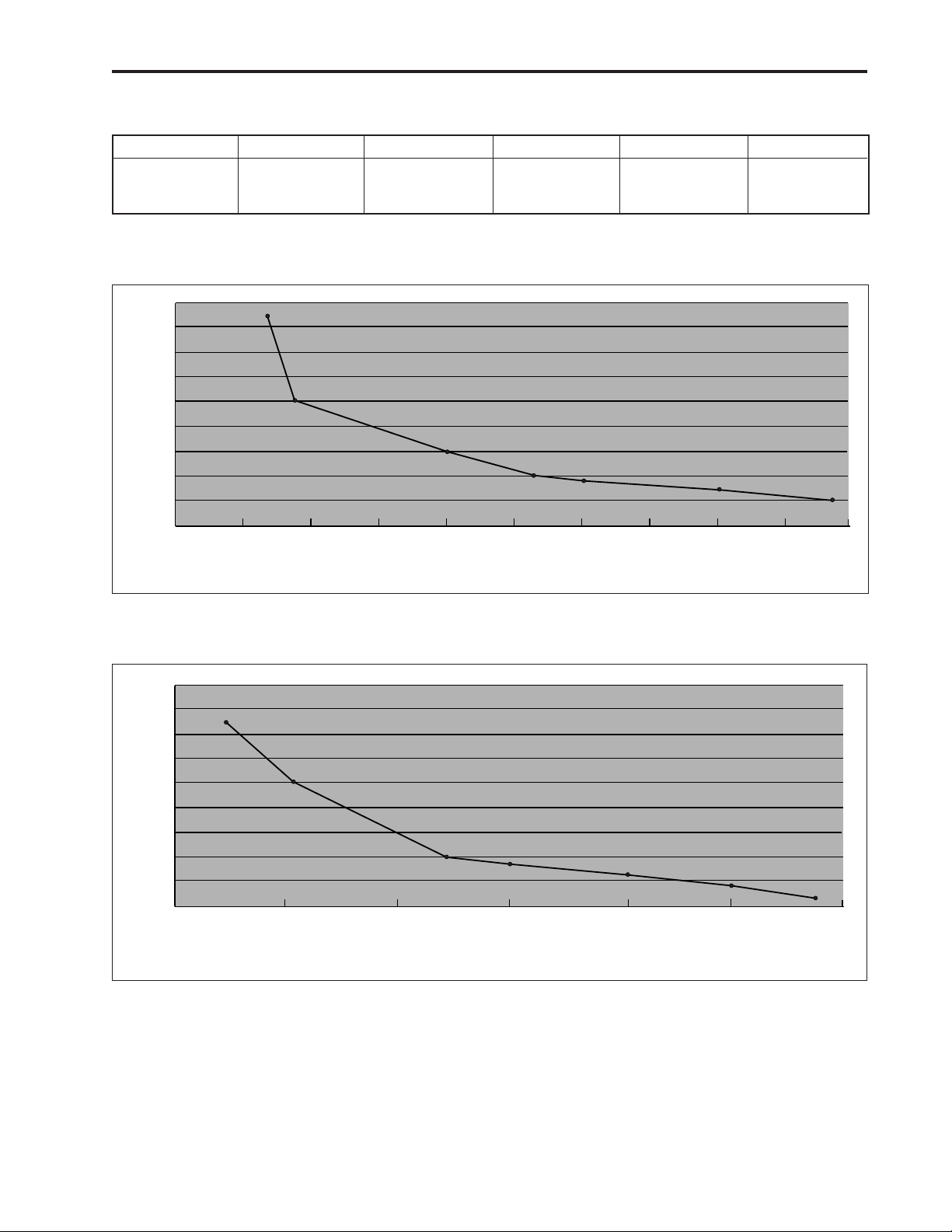
Continuous Delivery Battery Life with Alkaline Batteries
Rate Life Volume
0.4 ml/hr 338 hrs 135 ml
4 ml/hr 178 hrs 712 ml
10 ml/hr 112 hrs 1120 ml
15 ml/hr 96 hrs 1440 ml
30 ml/hr 53 hrs 1590 ml
75 ml/hr 18 hrs 1350 ml
125 ml/hr 15 hrs 1875 ml
Table 5. Two AA Alkaline-type batteries used with the CADD-Legacy™ pumps.
8
Page 12
Intermittent Delivery Battery Life with Alkaline Batteries
Dose Volume Duration Dose Cycle KVO Life Volume
23.5 ml 1:00 hr 5:00 hr 0.2 ml/hr 193 hr 915 ml
61 ml 1:00 hr 6:00 hr 0.2 ml/hr 120 hr 1224 ml
125 ml 1:00 hr 6:00 hr 0.2 ml/hr 65 hr 1356 ml
Table 6. Two AA Alkaline-type batteries used with the CADD-Legacy™ pumps.
135
120
105
90
75
60
45
Rate (ml/hr)
30
15
0
10
20 30
40 50
Hours
Figure 5. Operating time to low battery alarm using alkaline batteries.
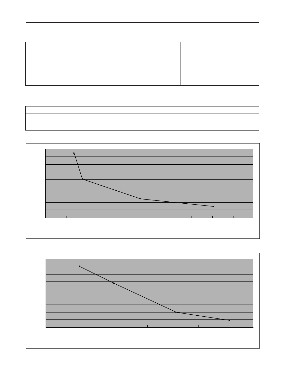
18
16
14
12
10
8
6
Rate (ml/hr)
4
2
0
50
100
150
200
Hours
60
250
70
80
300
90
100
350
Figure 6. Operating time to low battery alarm using alkaline batteries.
9
Page 13
Continuous Delivery Battery Life with Lithium Batteries
Rate Life Volume
0.4 ml/hr 413 hrs 165 ml
4 ml/hr 307 hrs 1228 ml
10 ml/hr 190 hrs 1900 ml
15 ml/hr 163 hrs 2445 ml
30 ml/hr 90 hrs 2700 ml
75 ml/hr 33 hrs 2475 ml
125 ml/hr 22 hrs 2750 ml
Table 7. Two AA Lithium-type batteries used with the CADD-Legacy™ pumps.
Intermittent Delivery Battery Life with Lithium Batteries
Dose Volume Duration Dose Cycle KVO Life Volume
23.5 ml 1:00 hr 5:00 hr 0.2 ml/hr 300 hrs 1458 ml
61 ml 1:00 hr 6:00 hr 0.2 ml/hr 185 hrs 1911 ml
125 ml 1:00 hr 6:00 hr 0.2 ml/hr 125 hrs 2625 ml
Table 8. Two AA Lithium-type batteries used with the CADD-Legacy™ pumps.
135
120
105
90
75
60
45
Rate (ml/hr)
30
15
0
Figure 7. Dual-stroke operating time on lithium batteries.
18
16
14
12
10
8
6
Rate (ml/hr)
4
2
0
50
Figure 8. Single-stroke operating time on lithium batteries.
20
100
40 60
150
80 100
200
Hours
250
Hours
120
300
140
350
160
400
180
200
450
10
Page 14

4 Construction
The pump’s housing is made of a special high
impact plastic. It is composed of two sections:
the rear and front housing. The pump housing
is sealed to ensure that the pump is water
resistant. The battery compartment is not
water resistant.
NOTE:
The CADD-Legacy
™
ambulatory infusion
pump is water resistant, but not waterproof.
The pump is “Splashproof” and is
characterized by the IEC code of IPX4.
The battery compartment is accessed through a
removable door on the rear housing. Within
the battery compartment is space for the
batteries and the four battery contacts.
On CADD-Legacy
Cassette
™
Reservoir or the administration set is
™
pumps the Medication
attached to the bottom of the pump by inserting
the two hooks on the cassette into the mating
hinge pins on the pump. The pump and the
reservoir or the administration set are then
placed in an upright position on a firm, flat
surface. The reservoir or the administration set
must be secured in place by inserting a coin (or
key if using the CADD-Legacy
™
PCA pump) in
the slot on the pump’s locking button, pushing
the button in and turning the button onequarter turn counter-clockwise.
NOTE:
The Medication Cassette
™
Reservoir and the
administration set are intended for single
use only.
The keyboard, located on the front housing, is
composed of eight membrane switches (nine
membrane switches on the CADD-Legacy
™
PCA pump) and is sealed against moisture. All
of the keys contain domes to provide a tactile
feel when the key is pressed. The keyboard
keys are sensed by the pump’s microprocessor.
The Liquid Crystal Display (LCD), also located
on the front housing, shows the pump status
and programmed settings. The dot matrix
display consists of 16 character columns with 2
rows of characters, and is selected by the
pump’s microprocessor according to status
conditions and keyboard entries.
The microprocessor and other circuitry which
control the pump are located on a printed
circuit board. The board contains the Central
Processing Unit (CPU), motor driver circuitry,
and other circuitry. The circuitry is designed to
reduce susceptibility to interference from
electromagnetic fields and to dissipate electrostatic discharge.
The LCD controller is mounted on the LCD
using chip on glass technology.
The pumping mechanism subassembly contains
the motor, gear train, camshaft, valves, expulsor, sensing disk, infrared light source, infrared
detector, occlusion sensors, disposable sensor,
and cassette locking button. Via the motor
driver circuitry, the pump’s microprocessor
controls motor rotation.
Two external port connectors are utilized for
remote dose and external power input. The
accessory jack is used for attachment of the
Remote Dose Cord (CADD-Legacy
™
PCA
pump only) and interface cable. The Remote
Dose Cord enables the patient to use either of
two options to begin a Demand Dose when
using the PCA delivery mode: (1) the Remote
Dose button; or (2) the
Í key.
The second port allows connection to an AC
adapter.
The keyboard is connected to the printed
circuit board via a flex circuit tail. Discrete
wires connect the pumping mechanism, motor,
and sensors to the printed circuit board.
The accessory jack in conjunction with the
interface cable allows download of events
using the CADD-DIPLOMAT
™
software.
11
Page 15

5 Theory of Operation
Keyboard Circuitry
The CADD-Legacy™ pumps are controlled by a
microprocessor. The actions of the microprocessor are controlled by a program, which is
contained in the memory.
Commands are issued to the microprocessor
from the user via the eight keys on the keyboard
(nine keys and Remote Dose Cord on
CADD-Legacy
keyboard are arranged in a 3x3 matrix which
feeds into the keyboard encoder. A key closure
applies a ground to the associated input of the
keyboard encoder. Key debounce circuitry
resident in the keyboard encoder provides a
clean output signal to the microprocessor for
the duration of the key closure. The microprocessor reads keyboard status by accessing
special memory locations in the keyboard
encoder.
The Remote Dose Cord button (CADD-Legacy
PCA pump only) consists of an SPDT switch
with one switch output going to the microprocessor and the other going to the keyboard
encoder. The switch has a common input line
and two output signal lines. The two signal lines
are complementary such that one line is always
logic high and the other is always low. When
the Remote Dose Cord button is pressed, both
signal lines change to the alternate logic state.
This redundancy prevents a single line failure
from starting a dose delivery.
The
Å button allows the pump to be placed in a
very low power mode by turning off all sensors
and LCD, but some battery energy is still used by
the electronics. To maximize battery life, remove
the batteries when pump is not in use.
™
PCA pump). The keys on the
Data Memory in Real Time Clock
RAM
Many settings of the pump’s delivery and
record-keeping parameters are stored by the
microprocessor in a Battery backed RAM in the
Real Time Clock. Data to and from the memory
is presented serially. Whenever the microprocessor uses data from the Real Time Clock, the
data is checked for validity.
EEPROM
Data describing the current delivery protocol is
stored in an EEPROM included in the microprocessor. Whenever this data is used, it is
checked for validity.
Battery Backed RAM
Additional settings of the pump’s delivery and
record keeping parameters are stored in a
battery backed Random Access Memory
(RAM). Battery backup is provided by a
printed circuit board-mounted lithium battery.
This battery provides a minimum of five years
of memory retention during normal pump
usage. Whenever the microprocessor uses data
from the RAM, the data is checked for validity.
™
Time Base Circuitry
An accurate 3.6864 MHz timebase is provided
by a quartz crystal. The 3.6864 MHz signal is
connected to the microprocessor, where it is
frequency-divided to access the program
memory at a cycle rate of 921 kHz.
In addition, an accurate 32.768 kHz timebase
is provided by a second quartz crystal. The
32.768 kHz signal is used for the real time
clock.
LCD Circuitry
The CADD-Legacy™ pumps feature a 2 line by
16 character Liquid Crystal Display (LCD).
The characters on this dot matrix display are
formed by a matrix of 5 by 7 dots. It is reflective only, with a black on silver appearance,
with no backlight.
The display includes a controller chip mounted
directly on the glass capable of interfacing with
4 and 8 bit systems to display 92 kinds of
characters, numerals, symbols, and special
characters under control of a built in character
generator ROM. A RAM is also included to
make other special characters possible.
12
Page 16

LED Indicator
A green Light Emitting Diode (LED) is provided under the pump’s front panel overlay to
provide pump power status to the user. When
this LED is lit, it indicates that an AC adapter
is being used to power the pump.
Flash PROM Technology
Program memory for the pump is stored in
Flash Programmable Read Only Memory
(Flash PROM). This type of memory allows
modification of the contents without physically
removing the device from the circuit board.
Under certain circumstances the program can
also be downloaded. Several layers of redundancy in the programming system prevent
accidental erasing or modification of the
PROM.
Audible Alarm Circuitry
Audible alarm circuitry consists of two piezo
electric disks and an independent oscillator.
The disks flex or bend in resonance with the
output of the oscillator. The piezo disks are
mounted to the pump housing to enhance
sound level.
The microprocessor controls the audible alarm
by selecting the alarm control line for more
than 0.5 seconds. The oscillator which drives
the piezo disks is capable of providing two
driving frequencies. The low frequency is in the
range of 700 to 1500 Hz and the high frequency is in the range of 1600 to 2500 Hz.
When the microprocessor selects the audible
alarm, the alarm enters a warble mode where it
oscillates between the low and high frequency
sound at a rate of 0.8 and 2 Hz.
Low battery voltage detection and watchdog
timer circuitry also have the ability to enable
the audible alarm via the microprocessor.
The audible alarm circuitry is backed up by a
super capacitor. The super capacitor provides
energy for the alarm in the instance where all
power is lost while pump is in the RUN mode.
There is enough energy in the super capacitor
to drive the audible alarm for 3 minutes when
the pump has been in the RUN mode for 2
minutes or longer.
Watchdog Timer Circuit
Watchdog timer circuitry is provided to monitor the status of the microprocessor. If the
microprocessor fails to function properly, the
watchdog circuit issues a reset signal which
disables the motor and enables the audible
alarm. To assure proper function, the microprocessor must strobe the watchdog circuit at
least once every second in order to prevent the
watchdog from performing its reset function.
The reset output from the watchdog circuit is a
pulse output. This acts to “jump start” the
microprocessor. This unique feature allows the
microprocessor to test the watchdog circuit on
every power-up. By setting a flag in memory
and not strobing the watchdog, the microprocessor can force a watchdog time-out. After
being reset, the microprocessor checks the
status flag to see if this was a time-out test. If
so, the microprocessor verifies the watchdog’s
ability to disable the motor and then continues
normal power-up activities.
If a reset occurs when the microprocessor is
not expecting it, the microprocessor traps the
event, sounds the audible alarm and displays
an error message on the LCD.
Motor Drive/Motor Watchdog
Circuit
The motor drive circuitry is composed of a
series of power FET transistors, passive components, and two voltage comparators. Built
into the motor drive circuitry is an RC timer
which times how long the motor runs each
time it is turned on. If the motor runs for more
than an average of 4 seconds, the circuit will
time out and disable the motor.
A unique feature of this circuit is that control
lines to and from the microprocessor circuit
allow the microprocessor to perform a complete functional test of the motor drive circuit
without running the motor. The microprocessor performs this test function every several
minutes to assure its continued functionality.
An input from the watchdog circuit prevents
motor operation if the watchdog timer expires.
Rotation of the motor is sensed by the microprocessor via an infrared-sensitive photo
detector. An infrared light source is mounted
13
Page 17

so that its light beam illuminates the infrared
detector. An opaque flag is mounted concentrically to the camshaft and rotates with it between the infrared light source and detector.
When the flag interrupts the light beam, the
output of the detector is sensed by the microprocessor via an input port bit. Power to the
infrared LED light source is controlled by the
motor drive circuit and is off when the motor
is not running to conserve battery life.
In the microprocessor software, multiple
checks are made on motion of the camshaft.
When the motor is commanded to start, the
infrared sensor must show that half a revolution has occurred within four seconds and that
the motor has stopped when half a rotation
was completed. In addition, no camshaft
rotation can take place when the motor has
not been commanded to run.
Power Circuitry
Power for the pump is normally supplied by
two AA alkaline batteries, two AA lithium
batteries, or an AC adapter. These types of
batteries have a fairly low internal resistance
over their discharge range, which will keep
power supply noise low. Other types of batteries, such as carbon-zinc, exhibit high internal
resistance, especially near depletion. A voltage
drop across the internal resistance occurs when
current is drawn by the motor during pump
activations. This current is demanded in short
pulses when the motor is first turned on and
generates large spikes in the battery voltage.
This noise can cause the low battery detection
circuit to shut down the pump.
The power from the two AA batteries is
boosted to +5VDC. This 5V is used to power
the motor and a 3.3V linear regulator. The
linear regulator provides power to all the other
circuitry including the microprocessor.
Voltage Reference Circuit
A voltage reference circuit provides a constant
DC voltage to the microprocessor Analog to
Digital Converter (ADC). By reading this input
and comparing the value to a predetermined
range, the microprocessor can validate the
accuracy of the 3.3-volt power supply. Variations in the 3.3-volt supply left undetected can
result in inaccuracy in the low battery alarm
set points and variations in other calculated
values. (Also refer to Voltage Detector Circuit
description on page 18.)
Pumping Mechanism
The pumping mechanism is linear peristaltic
with two active valves and an expulsor. Pumping occurs when the expulsor presses on the
reservoir pump tubing in sequence with the
inlet and outlet valves. At rest, the outlet valve
is pressing down fully on the tubing and the
expulsor and inlet valve are retracted. (See
Figure 9.)
Motor
Pump Housing
Expulsor
Occlusion Sensor
Cassette Hinge
Pump Tubing
Figure 9. A simulated pumping mechanism in a CADD-Legacy™ pump.
14
Camshaft
Lock Cassette
Upstream Sensor
Pressure Plate
Inlet Valve
Outlet Valve
Page 18

When the microprocessor commands the mechanism to pump, the camshaft begins to rotate,
thus controlling the following pump cycle:
1. The inlet valve closes.
2. In synchrony with the expulsor moving
down to compress the tubing, the outlet
valve opens, expelling 0.050 ml of fluid
toward the patient.
3. The outlet valve closes.
4. The inlet valve opens as the expulsor is
retracted, causing fluid from the reservoir to
again fill the pump tubing segment.
5. The camshaft rotation stops after half a
revolution and the cycle is completed.
The microprocessor uses its timer circuits to
accurately time the 18 seconds (in this example) between mechanism activations. The
timebase accuracy is ultimately determined by
the 3.6864 MHz quartz crystal oscillator.
Air Detector
The air detector is designed to detect air in the
outlet tubing fluid path. The air detector can be
set to On-high sensitivity, On-low sensitivity, or
Off by accessing Biomed Functions. When the
On-high sensitivity setting is selected the pump
will detect a single bubble greater than 0.100 ml.
When the On-low sensitivity setting is selected
the pump will detect a single bubble greater than
0.250 ml.
Pumping Characteristics
To deliver the amount of drug specified by the
parameter settings, the pump’s microprocessor
causes the pump mechanism to deliver fluid
“pulses” timed according to the desired rate.
At rates of 15 ml/hr or less the microprocessor
delivers a single pulse to the motor circuit
causing a half revolution of the camshaft and
fluid delivery in 0.05 ml increments. At rates
greater than 15 ml/hr the microprocessor
delivers two back to back pulses to the motor
circuit causing a full revolution of the camshaft
and fluid delivery in 0.1 ml increments. Thus,
to deliver 20 ml/hr, for example, the microprocessor solves these equations:
Mechanism activations per hr
= 20 ml per hr/0.1 ml per activation
= 20/0.1
= 200
Time (seconds) between activations
= 3600 sec per hr/number of activations per hr
= 3600/200
=18
NOTE:
At rates 15 ml/hr the pump delivers 0.05
ml per stroke. This allows a more continuous delivery at low rates.
Multi-bubble Sensing
The air detector is also designed to sense if an
accumulation of more than 1 ml of air has
passed through the outlet tubing path in the last
15 minutes. This feature is active anytime the air
detector is on.
The air detector is compatible with all of the
Medication Cassette
™
Reservoirs and CADD
®
Administration Sets indicated for use with the
CADD-Legacy
™
pump, and all pump accessories.
It is powered directly from the pump and no
additional power is required.
Theory of Operation
The air detector consists of sensor electronics and
two ultrasonic transducers positioned on opposite sides of the fluid path. One transducer acts as
an acoustic transmitter and the other as an
acoustic receiver. Air detection occurs when air in
the fluid path causes a reduction in the signal
level to the receiver. When the signal is interrupted for a preset length of time, the sensing
circuitry sends a signal to the microprocessor
indicating air in the fluid path. To maximize the
reliability of the system and to reduce false
alarms, the transmitted signal is swept over a
frequency range. This accommodates varying
resonance frequencies of the transducer and
reduces sensitivity to tubing tolerances and other
mechanical variations.
15
Page 19

Downstream Occlusion Sensor
The downstream occlusion sensor is designed
to detect excessive pressure in the outlet
tubing.
If the fluid path to the patient becomes blocked,
the pump tubing will expand as pumping
occurs. When there has been an amount of
inflation corresponding to 179.3 kPa ±
96.5 kPa, 1.79 (± 0.97) bar, or 26 (±14) psi,
the occlusion sensor trips, whereupon the
microprocessor stops the pump mechanism
and issues visual and audible alarms. Thus the
maximum pressure which can be developed is
276 kPa (2.76 bar, 40 psi).
Construction
The downstream occlusion sensor consists of a
membrane switch located on the bottom of the
pump next to the outlet valve. The switch is
fastened to the housing with an adhesive to
ensure that the overall assembly is water
resistant.
Theory of Operation
The membrane switch is in contact with the
outlet tubing when a cassette is installed.
Tubing expansion caused by a downstream
occlusion results in closure of the membrane
switch. Switch closure sends a logic low to the
microprocessor indicating a downstream
occlusion.
Upstream Occlusion Sensor
The upstream occlusion sensor detects an
occlusion in the inlet tubing which would
prevent or restrict the flow of fluid to the
pump.
Construction
The upstream occlusion sensor consists of a
strain gauge sensor located on the bottom of
the pump next to the inlet valve. The sensor is
fastened to the housing with an adhesive to
ensure that the overall assembly is water
resistant.
Theory of Operation
When a cassette is installed on the pump, the
inlet tubing is in contact with the sensor. In
order to conserve battery power, the upstream
occlusion sensor circuit is only activated while
the motor circuitry is enabled. Pressure on the
sensor is read just prior to the motor starting
and after the end of the motor stroke. The
microprocessor uses an average of the pressure
exerted by the unoccluded tubing to establish a
baseline pressure. If the tubing pressure at the
end of a motor stroke is below the baseline
pressure, the upstream tubing is occluded.
Cassette Attachment Detection
The pump uses the upstream occlusion sensor
and cassette present sensor to verify the presence of a cassette. If an infusion is started by
pressing
or if a cassette is improperly seated, the pump
will initiate a visual and audible alarm.
Theory of Operation
During manufacture of the pump, upstream
occlusion sensor readings are recorded for no
cassette installed and typical cassette installed.
These readings are used to calculate threshold
levels for cassette detection. When a cassette is
first attached to the pump, the new sensor
reading must be above the calculated threshold
level.
⁄ when there is no cassette installed
16
Additional readings are taken periodically
while the pump is in use. If the sensor readings
drop below the threshold when the motor is
off, or the cassette present sensor circuit does
not sense the presence of a cassette, the cassette
is considered removed.
Page 20

6 Safety Features and
Fault Detection
Hardware Safety Features
Key hardware safety features include a watchdog timer circuit, motor drive and motor
watchdog circuits, cassette present sensor
circuit, and a voltage detector circuit. Each
safety circuit performs a unique function to
insure the overall safety of the device. (See
Figure 10.)
Watchdog Timer Circuit
The microprocessor must send an appropriate
signal to the watchdog circuit at least once per
second. If the microprocessor does not, the
watchdog circuit will time out and shut down
the pump controller.
Watchdog timer circuitry is provided to monitor
the status of the microprocessor and disable
the motor and enable the audible alarm if the
microprocessor fails to function properly. The
microprocessor must strobe the watchdog
circuit at least once every second in order to
prevent the watchdog from performing its reset
function. The reset output from watchdog
circuit is a pulse output. This acts to “jump
start” the microprocessor. This unique feature
allows the microprocessor to test the watchdog
circuit on every power-up. By setting a flag in
memory and not strobing the watchdog, the
microprocessor can force a watchdog time-out.
After being reset, the microprocessor checks
the status flag to see if this was a time-out test.
If so, the microprocessor verifies the
watchdog’s ability to disable the motor and
then continues normal power-up activities. If
the reset occurred when the microprocessor
was not expecting it, the microprocessor traps
the event, sounds the audible alarm and displays an error message on the LCD.
Motor Drive/Motor Watchdog Circuit
Motor drive circuitry is composed of a series of
power FET transistors, passive components,
and two voltage comparators. Built into the
motor drive circuitry is an RC timer which
times how long the motor runs each time it is
turned on. If the motor runs for more than an
average of 4 seconds, the circuit will time out
and disable the motor. A unique feature of this
circuit is that control lines from the microprocessor can perform a complete functional test
of the motor drive circuit without running the
motor. The microprocessor performs this test
function every several minutes to assure its
continued functionality. An input from the
watchdog circuit prevents motor operation if
the watchdog timer expires.
PROGRAM
MEMORY
DATA
LCD DISPLAY VOLTAGE
▼
▼
▼
▼
CPU/IO
▼
▼
▼
▼
▼
▼
▼
MEMORY
KEYBOARD
Figure 10. CADD-Legacy™ pump hardware block diagram.
AUDIBLE
▼
ALARM
▼
MONITOR
MOTOR
▼
DRIVE
▼
▼
WATCHDOG
REAL-TIME
▼
CLOCK
▼
▼
MOTOR
▼
WATCHDOG
POWER
▼
INPUT
▼
SENSORS
17
Page 21

Voltage
Trip Point
2.4 V
Voltage
Trip Point
Source
Battery
Motor Status CADD-Legacy
Running/not running
No alarm
™
Pump Status
< 2.4 V
< 1.8 V
< 4.75 V
< 1.0 V
Battery
Battery
5 Volt supply
motor voltage
Battery
Not running
Running
Running
Running/not running
Table 9. CADD-Legacy™ pump low battery conditions.
Cassette Present Sensor Circuit
The cassette present sensor system consists of a
switch on the pump mechanism that interfaces
to the attached cassette and associated circuitry. This switch senses the presence of a
cassette.
When a cassette is latched to the pump, the
cassette presses against the switch in the pump
mechanism. Electronic circuitry on the circuit
board detects this and reports the information
to the microprocessor. This system acts as a
safety feature to detect a damaged or detached
cassette. If, during operation, the microprocessor detects the switch open, the pump will
enable audible and visual alarms and stop
delivery.
Redundancy with the upstream occlusion
sensor prevents single fault failures from
causing over or under delivery of fluid. Additional circuitry allows these sensors to be
turned on and off by the microprocessor to
conserve battery power.
Voltage Detector Circuit
Low voltage detection is performed by part of
the watchdog circuit and by the microprocessor via software. Three low voltage levels are
detected. The first two levels (Low Battery and
Battery Depleted) are detected by software and
the third by hardware.
The first level to be reached is the Low Battery
Warning threshold which occurs when the
battery voltage decays to a nominal value of
2.4 volts when motor is off or 1.8 volts when
motor is active. An Analog to Digital Con-
Audible alarm (3 beeps every 5 minutes); Low Bat
message appears
Audible alarm (3 beeps every 5 minutes); Low Bat
message appears
Battery Depleted message appears
Hardware reset occurs; Pump continues to indicate
depleted battery condition
†
†
††
verter (ADC) built into the microprocessor
allows the microprocessor, via software, to
monitor the battery voltage and motor voltage.
At the Low Battery Warning threshold, the
microprocessor enables a periodic series of
beeps and displays a “Low Bat” warning
message on the LCD.
The second level is Battery Depleted Warning
threshold. As the voltage operating the motor
reaches a nominal value of 4.75 volts, the
software disables delivery, places a “Battery
Depleted” message on the LCD, and enables a
continuous two tone audible alarm.
The third level is a hardware reset which is
reached when the battery voltage decays to a
nominal value of 1.0 volt. At this point a
hardware reset circuit is triggered which places
the microprocessor in reset. This prevents
ambiguous microprocessor operation as the
battery voltage continues to decay. The hardware reset continues until the battery is completely discharged or until it is removed. A
hardware reset can only be cleared by replacing the old batteries with two fresh ones.
†
The pump emits 3 beeps every 5 minutes, and the message
“Low Bat” appears on the pump’s display, indicating that
the battery power is low, but the pump is operable.
††
The pump emits a continuous, variable-tone alarm, and
the message “Battery Depleted” appears on the display, the
battery power is too low to operate the pump and pump
operation has stopped.
18
Page 22

Software Safety Features
Data Handling Software Safety Features
Hardware-related Software Safety Features
Program Memory Check
At power up and at regular intervals thereafter,
the program memory is tested by calculating a
Cyclic Redundancy Code (CRC) on the program
and then comparing it with the CRC stored with
the program. If the stored and calculated CRCs
do not match, the software will display a system
fault screen, turn on a continuous two-tone
audible alarm, and stop all drug delivery.
RAM Memory Check
At power up, the random access memory is
checked. A particular bit pattern is written to
and read from each address in the RAM. If the
read data is different from the written data, the
software will display a system fault screen, turn
on a continuous two-tone audible alarm, and
stop all drug delivery.
Motor Circuit Check
At power up and at regular intervals thereafter,
the motor circuit is checked to ensure that no
power is being applied to the motor unless the
motor is actually on. If the software detects
power being applied to the motor at any other
time, it will sound a continuous two-tone
audible alarm and will no longer attempt to
deliver medication. During every pump activation, the software checks to see whether the
motor completes one activation. If the motor
fails to turn, or fails to complete a cycle, the
software will display a system fault screen, turn
on a continuous two-tone audible alarm, and
stop all drug delivery.
Keypad Encoder Check
Key presses are routed to the microprocessor via
a keypad encoder. Every time the software
receives data from the keypad encoder, it is
checked. If the data is not a valid key press, the
software disregards it.
The keypad contains a redundant switch in the
⁄ key, ‹ key, and Í key (CADD-Legacy
PCA). The redundant switch in each of these
keys is routed to the microprocessor via an I/O
chip. The microprocessor must see a valid signal
simultaneously from the redundant switch and
the normal switch (routed through the keypad
encoder) before it will start infusing.
™
Data Stored in RAM
Before use, data associated with delivery and
stored in RAM is tested by calculating a CRC
on the data and then comparing it with the
CRC stored with the data. If the stored and
calculated CRCs do not match, the software
will display a system fault screen, turn on a
continuous two-tone audible alarm, and stop
all drug delivery.
Data Stored in EEPROM
Before use, data associated with delivery and
stored in EEPROM is tested by calculating a
CRC on the data and then comparing it with
the CRC stored with the data. If the stored and
calculated CRCs do not match, the software
will display a system fault screen, turn on a
continuous two-tone audible alarm, and stop
all drug delivery.
Data Stored in NOVRAM
Before use, data associated with delivery and
stored in NOVRAM is tested by calculating a
CRC on the data and then comparing it with
the CRC stored with the data. If the stored and
calculated CRCs do not match, the software
will display a system fault screen, turn on a
continuous two-tone audible alarm, and stop
all drug delivery.
Data Used in Calculations
Calculations on data used in some way to
control the delivery of drug are performed
redundantly. The two calculated values are
then compared. If the two values do not match,
the software will display a system fault screen,
turn on a continuous two-tone audible alarm,
and stop all drug delivery.
Timer Data Registers
The data in the timer Real Time Clock is
checked at regular intervals. If the data is not
reasonable, the software will turn on a continuous two-tone audible alarm and stop all
drug delivery.
19
Page 23

7 Hardware and Software
Fault Detection
Overview
If the CADD-Legacy™ pump displays an error
code, a hardware or software fault has been
detected by the microprocessor, and the pump
should be returned for servicing.
When hardware or software faults are detected
by the microprocessor, pump operation stops
and a continuous two-tone audible alarm will
be activated. An error message will be displayed on the LCD. On the next power up, the
error code will again be displayed. If the error
detected was a data fault, the pump will be in
Lock Level 2, and all other programmed
functions will have default values. (See the
pump’s Operator’s Manual for specific defaults.)
Order of Error Code Events
1. There is a continuous two-tone audible
alarm and the display will read
Error Detected
Error Code Description
Range
1010-1040 Software Application Errors
1110-1160 Software Control Errors
1210-1270 CRC Errors
1310-1340 Real Time Clock Errors
1410-1450 Standard Delivery Calcula-
tion Errors
1510-1530 Air Detector System Errors
1610-1670 CPU Test Errors
1710-1720 Miscellaneous Hardware
Errors
1810-1872 Motor Errors
Table 10. CADD-Legacy™ pump error codes.
E(XXXX)
NOTE:
“XXXX” is a 4-digit code.
2. To silence the error code alarm, remove the
batteries.
3. At each subsequent power up the pump will
display the initial power up screen and then
the following screen:
LEC XXXX
Thus there is always a display of the “Last
Error Code (LEC)” detected by the microprocessor.
20
Page 24

8 Cleaning and Inspection
Procedures
Inspection Recommendation
Deltec recommends annual functional inspection on the CADD-Legacy
PLUS, and CADD-Legacy™ PCA pumps. The
following inspection procedures should be
performed annually to verify function and
accuracy.
NOTE:
Persons performing the following tests and
procedures should be familiar with the
Deltec CADD-Legacy
the Operator’s Manual supplied with the
pump before proceeding.
WARNING:
CADD-Legacy
™
pumps are sealed units. A
broken or damaged seal will, therefore, be
considered conclusive evidence that the
pump has been misused and/or altered,
which voids any and all warranties. All
service and repair of CADD-Legacy
must be performed by Deltec or its authorized agents.
™
1, CADD-Legacy
™
pump. Please read
™
pumps
™
Cleaning
Use any of the following solutions to clean the
pump and accessories:
• Soap solution
• Benzalkonium chloride concentrate (0.13%)
• Glutaral concentrate, USP (2%)
• 10 percent solution of household bleach (one
part household bleach to nine parts water)
• Alcohol, USP (93%)
• Isopropyl Alcohol, USP (99%)
• PDI - Super Sani-Cloth
• Mada Medical - MadaCide
®
1. Dampen a soft, lint-free cloth with cleaning
solution. Apply the solution to exterior
surface of the pump or accessory. Do not
allow the solution to soak into the pump or
accessory.
2. Wipe the entire surface dry with another
soft, lint-free cloth. Allow the pump to dry
completely before use.
CAUTION:
• Do not immerse the pump in cleaning fluid
or water. Do not allow solution to soak into
the pump, accumulate on the keypad, or
enter the battery compart-ment. Moisture
build-up inside the pump may damage the
pump.
• Do not clean the pump with acetone, other
plastic solvents, or abrasive cleaners, as
damage to the pump may occur.
Battery Contact Cleaning
Pump battery contact cleaning can be performed easily using a clean cotton swab wetted
with Isopropyl Alcohol or by using a premoistened Alcohol swab. Use a minimum of
70% concentration by volume Isopropyl
Alcohol. Do not use Alcohol formulation that
has other additives besides Alcohol and water.
• Using a cotton swab wetted with Alcohol or
the pre-moistened Alcohol swab, rub with
medium pressure over the entire contact
surface a minimum of ten back and forth
cycles (twenty total wipes over the contact).
• Select a fresh surface of the swab and repeat
the cleaning process on the second battery
contact. Dispose of the swab when finished.
• Using a second Alcohol wetted swab, rub
over each contact surface again a minimum
of four back and forth cycles (eight total
wipes over the contact). Allow the contacts
to dry for a few minutes.
• 70% Chlorohexine
21
Page 25

Visual Inspection
Mechanical Inspection
• Visually inspect the pump for any damage to
the LCD, occlusion sensor seals, valves and
expulsor, cassette hinge area, cassette lock,
cassette sensor, keypad, indicator light,
power jack, accessory jack, air detector, and
housing. If any damage is noted, the pump
should be returned for service.
• Check the battery door for proper operation.
It should not be broken or damaged. The
battery door mating tabs on the pump
housing should not be broken or damaged.
• Examine the battery compartment for
damage. If the battery contacts appear
corroded, clean them as instructed on page
20. If the battery contacts appear to be bent
or pushed in, straightening may be possible
with a small screwdriver or other suitable
tool. Care must be taken not to damage the
pump housing or to incur further damage to
the contacts.
• Press each key on the keypad. Each key
should have a distinctive dome feeling. The
keys should not feel flat.
• Attach the battery door. The battery door
should fit snugly in place when it is closed on
the pump.
• Attach either a 50-ml or 100-ml Medication
Cassette
™
Reservoir or a CADD® Administration Set to the pump. Using a coin (key
for the CADD-Legacy
™
PCA pump), turn the
lock 1/4 turn counter-clockwise. Check for
smooth operation and a definite feel when
the lock pulls the cassette firmly against the
bottom of the pump. The slot on the cassette
lock should be aligned with the “LOCKED”
indicator on the side of the pump.
• Gently twist and pull on the cassette to make
sure it is firmly attached.
22
Page 26

9 Testing Procedures
Testing Recommendation
Deltec recommends annual functional testing
on the CADD-Legacy
testing procedures should be performed annually to verify function and accuracy.
NOTE:
To perform the following functional tests
the pump must be in Lock Level 0.
™
pumps. The following
Changing to Lock Level 0 (LL0)
Before programming the pump, make sure the
lock level is 0. LL0 allows the operator to
access all programming and operating functions.
1. Make sure the pump is stopped. Press
The current lock level will appear. (If the
lock level is already LL0, press
2. Press
3. Press
4. Press
5. Press
´ or Î until “LL0” appears.
Œ again or ¤. “Code 0” will
appear.
´ or Î until the Lock Level Code
“63” appears for CADD-Legacy
“64” for CADD-Legacy
CADD-Legacy
™
PLUS.
™
Œ or ¤ to set the new lock level.
„ to exit.)
1 or “65” for
™
PCA,
Œ.
CADD-Legacy™ PCA Pump
Power-up Check
• Insert batteries or press Å and observe the
LCD during power up. The first screen will
display the serial number, model number,
and software number with revision level.
The second screen will display 32 character
blocks. (If “LEC” and four digits appear
prior to the pump displaying the 32 character blocks, the pump has experienced an
electrical or mechanical fault and should be
returned for service.) If no error message is
immediately shown, the pump has powered
up normally. The pump will then sequentially display all of the programmed values
and beep at each screen. After all screens are
displayed, successful power up is indicated
with six audible beeps and the “STOPPED”
screen displayed. Continue with the Lock
check.
To Access Biomed Functions Loop
1. Press Œ. The current lock level will
appear.
2. Press
3. Press
Œ or ¤. “CODE 0” will appear.
´ or Î until the Biomed function
code “163” appears (Lock Code +100).
Then press
Œ or ¤.
Air Detector ON/OFF
1. Press „ until “Air Detector” appears.
2. Use
3. Press
´ or Î to select “Off.”
¤ to enter the change.
Lock Check
• Attach a 50- or 100-ml Medication Cas-
™
sette
Reservoir or a CADD® Administration Set to the pump. The mark on the
Cassette Lock button should be aligned with
the “Locked” symbol.
Cassette Sensor Check
• Unlock the cassette by inserting a key into
the lock and turning clockwise.
• The pump should issue an audible alarm and
the display should read “No Disposable
Clamp Tubing”.
• Press
⁄ or „ to silence the alarm. Press
and hold
The following three checks (LCD, Motor
and Gear Train, and Reservoir Volume
Empty Alarm Check) should be performed
in the sequence shown.
Å to turn the pump off.
LCD Check
• With the pump turned off, press Å. The
second screen that the pump displays will
consist of 32 blocks of characters. Examine
the LCD to verify that there are no missing
dark pixels in the character blocks.
23
Page 27

Testing Procedures - CADD-Legacy™ PCA pump continued
Motor and Gear Train Check
• Program the Reservoir Volume to 2.0 ml.
• Attach either a 50- or 100-ml Medication
Cassette
tion Set to the pump. Lock the cassette.
• Press and hold
dashes appear. Release
‹
motor for excessive noise or grinding
sounds. Count the number of pump activations. The pump should prime ten double
activations and then stop. Press
return to main menu.
™
Reservoir or CADD® Administra-
until three series of
‹
. Press and hold
‹
. While priming the pump, listen to the
„ to
Reservoir Volume Empty Alarm Check
• Program the Reservoir Volume to 1.0 ml.
Press
played on the LCD. Press
1.0 ml is displayed. Then press
• Press and hold
dashes appear. Release
‹
activations and then stop. The pump will
alarm and display “Reservoir Volume
Empty.” Press
until Reservoir Volume is dis-
„
´ or
until three series of
‹
. Press and hold
‹
. The pump should prime ten double
.
„
Î
¤
until
.
Starting/Stopping the Pump
• Program the pump with the following
values:
Reservoir Volume: 1.0 ml
Units: milliliters
Continuous Rate: 50 ml/hr
Demand Dose: 0.00 ml
Given: 0.00 (Press
• Program the Air Detector Off.
• Press and hold
followed by three sets of dashes, each accompanied by a beep. A review of the
programmed parameters then appears. The
main screen should appear with “RUN” in
the display.
• To stop the device, press and hold
“Stopping” appears followed by three sets of
dashes that disappear one at a time, each
accompanied by a beep. The main screen
should appear with “STOPPED” in the
display.
⁄.
)
¤
“Starting” appears
⁄
.
Activation Timing Check
• Reprogram the Reservoir Volume to 1.0 and
clear the Given screen.
• Press and hold
disappear from the display. The pump
should sequentially display all of the programmed values. Start a timer at the first
motor activation.
• Count the activations. One activation should
occur every six seconds. Approximately
sixty-six seconds and ten activations later,
the Reservoir Volume alarm should occur.
The display should show “Reservoir Volume
Empty.”
until three dashes
⁄
DOSE Key Check
(CADD-Legacy™ PCA pump only)
• Check the
ming the pump with the following values:
Reservoir Volume: 10.0 ml
Units: Milliliters
Continuous Rate: 0.0 ml/hr
Demand Dose: 1.00 ml
Dose Lockout: 00 hrs 5 min
Doses Per Hour: 12
Doses Given: 0 doses (Press
key operation by program-
Í
¤ to clear)
Doses Attempted: 0 doses (Press
¤ to clear)
Given: 0.00 ml (Press
¤ to clear)
• Press and hold
sequentially display all of the programmed
values.
• After “RUN” appears on the display, press
and note the time. The pump should
Í
beep twice and begin to deliver. Count the
number of pump activations. The pump
should make ten double activations. After
ten double activations, the display should
show a Reservoir Volume of 9.0 ml. Press
two more times within the next 5
Í
minutes. The pump should not deliver.
Remote Dose Cord Check
(CADD-Legacy™ PCA pump only)
• Wait 5 minutes after the dose given above;
then, instead of pressing
button on the Remote Dose Cord. The pump
should make ten double activations. After
ten double activations, the display should
show a Reservoir Volume of 8.0 ml. Press
. The pump should
⁄
Í
, press the
24
Page 28

Testing Procedures - CADD-Legacy™ PCA pump continued
the Remote Dose Cord button two more
times within the next 5 minutes. The pump
should not deliver.
Doses Given and Doses Attempted Check
(CADD-Legacy™ PCA pump only)
• Stop the pump by pressing and holding
Use
screen. The screen should show 2. Use
to advance to the Doses Attempted screen.
The display should show 6. (If the above
steps have not been followed exactly, different values may appear.)
to advance to the Doses Given
„
⁄
„
GIVEN Mode Check
• Press „ to advance to the Given screen.
The display should now show
2.00 ml. (If the above steps have not been
followed exactly, a different value may
appear.)
• Press the
show 0.00 ml.
¤ key. The display should now
Air Detector Test
This test will verify the function of the air
detector. To perform this test, the air detector
must be turned on. The previous program from
the
Í key check can be used to perform this
test.
• Attach an empty Medication Cassette
Reservoir or CADD® Administration Set to
the pump.
™
• Start the pump.
• Deliver a demand dose. (NOTE: Five minutes must have passed since the delivery of
the last demand dose.)
• The pump should deliver the dose without
.
an air detection alarm.
Upstream Occlusion Sensor Test
• Verify that the Upstream Occlusion Sensor is
turned on. (See page 23, To Access Biomed
Functions Loop.)
• Obtain a CADD
bag spike and anti-siphon valve. Also obtain
a clamp (slide clamp or hemostat).
• Insert the CADD
into an appropriate, standard IV bag filled
with water. Attach the cassette to the pump.
Prime the entire fluid path.
• Program the pump to deliver a continuous
maximum rate. Press and hold
the pump.
• Clamp the tubing halfway between the IV
bag and the pump. The pump should alarm
within three activations after clamping the
tubing.
®
Administration Set with
®
Administration Set spike
to start
⁄
Occlusion Pressure Range Tests
Occlusion Pressure Range Test I
• Secure it using the lock button.
• Thread the tubing through the air detector
groove.
• Start the pump.
• The pump should respond with a continuous
two-tone alarm and the display should read:
“Air In Line Detected”
• Press
• Now attach a Medication Cassette
• Secure it using the lock button.
• Thread the tubing through the air detector
„ or ⁄ to silence the alarm, and
remove the Medication Cassette
or CADD
voir containing fluid, or a primed CADD
Administration Set to the pump. Make
certain there is no air in the fluid path.
groove.
®
Administration Set.
™
Reservoir
™
Reser-
®
Description
Pressure is generated by activating the pumping mechanism with an attached filled,
clamped Medication Cassette
pump is started and a Demand Dose is given
until the high pressure alarm sounds.
Equipment needed
50- or 100-ml Medication Cassette
containing distilled water
Procedure
1. Insert two AA batteries and wait for the
pump to power up.
2. Attach a Medication Cassette
containing water to the pump. Lock the
cassette.
™
Reservoir. The
™
Reservoir
™
Reservoir
25
Page 29

Testing Procedures - CADD-Legacy™ PCA pump continued
3. Prime the Medication Cassette™ Reservoir
tubing. The tubing should be filled with
fluid to the end of the luer lock connector.
The system must be free from air bubbles
for this test.
4. Close the slide clamp on the distal end of
the tubing near the female luer of the
™
Medication Cassette
Reservoir.
5. Program the pump to the following parameters:
Reservoir Volume: 10.0 ml
Units: Milliliters
Continuous Rate: 0.00 ml/hr
Demand Dose: 1.00 ml
Dose Lockout: 00 hrs 5 min
Doses Per Hour: 12
Dose Given: 0 (Press
¤ to
clear)
Dose Attempts: 0 (Press
¤ to
clear)
Milligrams Given: 0.00 ml (Press
¤
to clear)
6. Start the pump. When the pump is running,
activate a Demand Dose, noting when the
high pressure alarm is activated.
Equipment needed
• Pressure gauge, 40 psi ± 1 psi (2.76 bar ± 0.07
bar)
• Pressure vessel, partially filled with water
• Pressure regulator, 40 psi (2.76 bar ± 0.07 bar)
• 50 or 100 ml Medication Cassette
™
Reservoir
containing water
CAUTION:
At the completion of the test, the pressure must be
reduced to zero before detaching the cassette from
the pump; otherwise, the cassette may rupture.
Safety glasses should be worn while conducting or
observing this test.
Procedure
1. Insert two AA batteries and wait for the pump
to power up.
2. Attach a Medication Cassette
™
Reservoir to the
pump. Lock the cassette.
NOTE:
The pressure from the source must be zero
when the cassette is attached.
7. The pump should alarm when the pump
delivers between 1 and 2 activations.
Occlusion Pressure Range Test II
Description
An adjustable metered pressure source is
connected to the Medication Cassette
voir tubing. The pressure is slowly increased
until the high pressure alarm sounds.
1998-11-22 D. Zurn
«Lgc Occlusion Setup»
40
PSI
Pressure GaugeRegulator
™
Reser-
3. Assemble the apparatus as shown in Figure 11.
4. Connect the Medication Cassette
™
Reservoir
outlet tube to the metered pressure source.
NOTE:
Do not use a CADD
®
Extension Set with
Anti-siphon Valve.
5. Program the pump for a continuous rate of
50 ml/hr. Press
⁄.
6. Slowly increase the back pressure, noting
when the high pressure alarm is activated.
NOTE:
The pressure may be increased rapidly to 8 psi
(0.55 bar), after which the pressure should be
increased at 3 psi/min (0.21 bar/min) or less
until the alarm sounds.
7. The high pressure alarm should sound within
1.79 (±0.97) bar, or 26 (±14) psi.
Figure 11. Occlusion test set-up.
26
Page 30

Testing Procedures - CADD-Legacy™ PCA pump continued
Accuracy Testing
Gravimetric Accuracy Testing
Description
A Medication Cassette
filled with water and weighed. The cassette is
then attached to the pump and the pump is set
to deliver a certain amount of water. The
cassette is then removed and weighed again.
The amount of water delivered is compared to
the amount that the pump should have delivered.
Nominal system accuracy is given in the technical specifications section for the pump. That is,
under the test conditions described below, the
accuracy of the pump and Medication Cassette
Reservoir will be nominal with a 90% confidence level. The nominal test conditions are as
follows: degassed water at 25 ± 5°C without
back pressure.
Equipment needed
• 50- or 100-ml Medication Cassette
voir
• 50 or 60 ml syringe
• CADD
®
Extension Set with Anti-siphon Valve
™
Reservoir is partially
™
Reser-
3. Weigh the entire Medication Cassette
™
Reservoir/CADD® Extension Set assembly
and record the weight. This is the pre-
delivery weight. (This weight includes the
empty Medication Cassette
CADD
®
Extension Set, and weight of the
™
Reservoir,
water.)
4. Attach the Medication Cassette
™
Reservoir to
the pump. Program the reservoir volume to
20 ml. Now press
¤. This value is the
intended delivery volume. Remove the slide
clamp.
5. With the pump in Lock Level 0, program a
continuous rate of 50 ml/hr. Start the pump
and deliver 20 ml.
™
6. Again, secure the slide clamp as close as
possible to end of the CADD
®
Extension Set
luer lock connector. Remove the Medication
Cassette
weigh the entire Medication Cassette
™
Reservoir from the pump and
™
Reservoir/CADD® Extension Set assembly.
This is the post-delivery weight.
7. Calculate the difference in weight between
the pre-delivery weight and the post-delivery
weight. This is the weight of the amount
delivered. (1 ml of water at 20° weighs 1
gram.)
• A balance accurate to 0.1 g
• 40 ml of room temperature water
Procedure
1. Fill the 50 or 60 ml syringe with 40 ml of
water. Transfer the water into a
Medication Cassette
™
Reservoir.
8. Find the difference between the volume of
the amount delivered and the intended
delivery volume. This is the inaccuracy
volume.
9. Divide the inaccuracy volume by the intended delivery volume and multiply by 100.
This is the accuracy error percentage. (See
Table 11.)
2. Remove any air from the Medication Cas-
™
sette
Reservoir by aspirating the air with
the syringe. Attach the CADD
®
Extension
Set with Anti-siphon Valve. Prime the tubing
so it is filled with fluid to the end of the
CADD
®
Extension Set luer lock connector.
10.If the accuracy error percentage is greater
than ± 6%, repeat the test with a new Medication Cassette
™
Reservoir. If the pump fails
a second time, call Deltec’s Customer Service
Department.
Pre- Post- Weight of Intended Inaccuracy Accuracy Accuracy
Delivery Delivery Amount Delivery Volume Error Error Percentage
Weight Weight Delivered Volume
61.1 g 41.6 g 19.5 g = 19.5 ml 20 ml -0.5 ml -0.5 ml ÷ 20.0 ml = -0.025 x 100 = -2.5%
-0.025
Table 11. Gravimetric percentage calculation
27
Page 31

Testing Procedures - CADD-Legacy™ PCA pump continued
Example:
Pre-delivery Weight: 61.1 g
Post-delivery Weight: – 41.6 g
Weight of Amount Delivered: 19.5 g
= 19.5 ml
Volume of Amount Delivered: 19.5 ml
Intended Delivery Volume: – 20.0 ml
Inaccuracy Volume: -0.5 ml
Inaccuracy Volume: -0.5 ml
Intended Delivery Volume: ÷ 20.0 ml
Accuracy Error: -0.025
x 100.00
Accuracy Error Percentage = -2.5%
Volumetric Accuracy Testing
Description:
A predetermined amount of water is delivered
into a collection device such as a burette or
graduated cylinder. The amount of water
delivered is compared to the amount that the
pump should have delivered.
Nominal system accuracy is given in the
technical specifications section for the pump.
That is, under the test conditions described
below, the accuracy of the pump and Medication Cassette
a 90% confidence level. The nominal test
conditions are as follows: degassed water at 25
± 5°C without back pressure.
Equipment needed:
• 50- or 100- ml Medication Cassette
voir
• 50- or 60- ml syringe
• CADD
Valv e
• A fluid collection device such as a burette or
a class A 25 ml capacity graduated cylinder
™
Reservoir will be nominal with
™
®
Extension Set with Anti-siphon
Reser-
• 40 ml of room temperature water
NOTE:
The test procedure calls for the use of a
Medication Cassette
CADD
®
Extension Set with Anti-siphon
Valve. An IV bag and CADD
™
Reservoir and a
®
Administration Set with integral or add-on antisiphon valve can be substituted for the
Medication Cassette
®
CADD
Extension Set with Anti-siphon
™
Reservoir and
Valve.
Procedure:
1. Fill the 50- or 60-ml syringe with 40 ml of
water. Transfer the water into a
Medication Cassette
™
Reservoir.
2. Remove any air from the Medication
Cassette
with the syringe. Attach the CADD
™
Reservoir by aspirating the air
®
Extension Set with Anti-siphon Valve. Prime the
tubing so it is filled with fluid to the end of
the CADD
®
Extension Set luer lock connec-
tor.
3. Insert the end of the CADD
®
Extension Set
into the fluid collection device.
4. Attach the Medication Cassette
™
Reservoir
to the pump. Program the Reservoir Volume
to 20 ml. This is the intended delivery
volume. Remove all clamps.
5. Program a continuous rate of 50 ml/hr.
Start the pump and deliver 20 ml.
6. When delivery is complete, record the
volume of fluid delivered. This is the actual
delivery.
7. Find the difference between the volume of
the amount delivered and the intended
delivery volume. This is the inaccuracy
volume.
8. Divide the inaccuracy volume by the intended delivery volume and multiply by
100. This is the accuracy error percentage.
(See Table 12.)
Intended Actual Inaccuracy Accuracy Accuracy
Delivery Delivery Volume Error Error Percentage
Volume Volume
20 ml 19.5 ml -0.5 ml -0.5 ml ÷ 20.0 ml = -0.025 -0.025 x 100 = -2.5%
Table 12. Volumetric percentage calculation
28
Page 32

9. If the accuracy error percentage is greater
than ± 6%, repeat the test with a new
Medication Cassette
pump fails a second time, call Deltec’s
Customer Service Department.
Example:
Actual Delivery Volume: 19.5 ml
Intended Delivery Volume: – 20.0 ml
Inaccuracy Volume: = -0.5 ml
Inaccuracy Volume: -0.5 ml
Intended Delivery Volume: ÷ 20.0 ml
Accuracy Error: -0.025
Accuracy Error Percentage: = -2.5%
™
Reservoir. If the
x 100.00
CADD-Legacy™ 1 Pump
Power-up Check
• Insert batteries or press Å and observe the
LCD during power up. The first screen will
display the serial number, model number,
and software number with revision level.
The second screen will display 32 character
blocks. (If “LEC” and four digits appear
prior to the pump displaying the 32 character blocks, the pump has experienced an
electrical or mechanical fault and should be
returned for service.) If no error message is
immediately shown, the pump has powered
up normally. The pump will then sequentially display all of the programmed values
and beep at each screen. After all screens are
displayed, successful power up is indicated
with six audible beeps and the “STOPPED”
screen displayed. Continue with the Lock
check.
To Access Biomed Functions Loop
1. Press
appear.
2. Press
3. Press
code “164” appears (Lock Code +100).
Then press
Air Detector ON/OFF
1. Press
2. Use
3. Press
. The current lock level will
Œ
or
Œ
or Î until the Biomed function
´
Œ
until “Air Detector” appears.
„
or Î to select “Off.”
´
to enter the change.
¤
. “CODE 0” will appear.
¤
or
¤
.
Lock Check
• Attach a 50- or 100-ml Medication Cas-
™
sette
Reservoir or a CADD® Administration Set to the pump. The slot on the Cassette Lock button should be aligned with the
“Locked” symbol.
Cassette Sensor Check
• Unlock the cassette by inserting a coin into
the latch and turning clockwise.
• The pump should issue an audible alarm and
the display should read “No Disposable
Clamp Tubing”.
• Press
⁄ or „ to silence the alarm. Press
and hold
The following three checks (LCD, Motor
and Gear Train, and Reservoir Volume
Empty Alarm Check) should be performed
in the sequence shown.
Å to turn the pump off.
LCD Check
• With the pump turned off, press Å. The
second screen that the pump displays will
consist of 32 blocks of characters. Examine
the LCD to verify that there are no missing
dark pixels in the character blocks.
Motor and Gear Train Check
• Program the Lock Level to LL0. Program the
Reservoir Volume to 2.0 ml.
• Attach either a 50- or 100-ml Medication
Cassette
tion Set to the pump. Lock the cassette.
• Press and hold
dashes appear. Release
‹
motor for excessive noise or grinding
sounds. Count the number of pump activations. The pump should prime ten double
activations and then stop. Press
return to the main menu.
™
Reservoir or CADD® Administra-
until three series of
‹
. Press and hold
‹
. While priming the pump, listen to the
„ to
Reservoir Volume Empty Alarm Check
• Program the Reservoir Volume to 1.0 ml.
• Press and hold
dashes appear. Release
. The pump should prime ten double
‹
activations and then stop. The pump will
alarm and display “Reservoir Volume
Empty.” Press
until three series of
‹
‹
.
„
. Press and hold
29
Page 33

Testing Procedures - CADD-Legacy™ 1 pump continued
Starting/Stopping the Pump
• Program the pump with the following
values:
Reservoir Volume: 1.0 ml
Rate: 3000 ml/24hrs
⁄
¤
.
Given: 0.0 ml (press
to clear)
• Program the Air Detector Off.
• Press and hold
followed by three sets of dashes, each accompanied by a beep. A review of the
programmed parameters then appears. The
main screen should appear with “RUN” in
the display.
• To stop the device, press and hold
“Stopping” appears followed by three sets of
dashes that disappear one at a time, each
accompanied by a beep. The main screen
should appear with “STOPPED” in the
display.
“Starting” appears
⁄.
Activation Timing Check
• Reprogram the Reservoir Volume to 1.0 and
clear the Given screen.
• Press and hold
disappear from the display. The pump
should sequentially display all of the programmed values. Start a timer at the first
motor activation.
• Count the activations. One activation should
occur every three seconds. Approximately
twenty-seven seconds and ten activations
later, the Reservoir Volume alarm should
occur. The display should show “Reservoir
Volume Empty.”
until three dashes
⁄
GIVEN Mode Check
• Press „ to advance to the Given screen.
The display should now show 1.00 ml. (If
the above steps have not been followed
exactly, a different value may appear.)
• Press the
show 0.00 ml.
¤ key. The display should now
• Attach an empty Medication Cassette
Reservoir or CADD® Administration Set to
the pump.
• Secure it using the lock button.
• Thread the tubing through the air detector
groove.
• Start the pump.
• The pump should respond with a continuous
two-tone alarm and the display should read:
“Air In Line Detected”
• Press
• Now attach a Medication Cassette
• Secure it using the lock button.
• Thread the tubing through the air detector
• Program the Reservoir Volume to 1.0 ml.
• The pump should deliver without an air
„ or ⁄ to silence the alarm, and
remove the Medication Cassette
or CADD
voir containing fluid or a primed CADD
Administration Set to the pump. Make
certain there is no air in the fluid path.
groove.
Start the pump.
detection alarm.
®
Administration Set.
™
™
Reservoir
™
Reser-
®
Upstream Occlusion Sensor Test
• Verify that the Upstream Occlusion Sensor is
turned on. (See page 29, To Access Biomed
Functions Loop.)
• Obtain a CADD
bag spike and anti-siphon valve. Also obtain
a clamp (slide clamp or hemostat).
• Insert the CADD
into an appropriate, standard IV bag filled
with water. Attach the cassette to the pump.
Prime the entire fluid path.
• Program the pump to deliver a continuous
maximum rate. Press and hold
the pump.
®
Administration Set with
®
Administration Set spike
to start
⁄
Air Detector Test
This test will verify the function of the air
detector. To perform this test, the air detector
must be turned on. The previous program from
the Activation Timing Check can be used to
perform this test.
30
• Clamp the tubing halfway between the IV
bag and the pump. The pump should alarm
within three activations after clamping the
tubing.
Page 34

Testing Procedures - CADD-Legacy™ 1 pump continued
Occlusion Pressure Range Tests
Occlusion Pressure Range Test I
Description
Pressure is generated by activating the pumping mechanism with an attached filled,
clamped Medication Cassette
pump is started and a Demand Dose is given
until the high pressure alarm sounds.
Equipment needed
50- or 100-ml Medication Cassette
containing distilled water.
Procedure
1. Insert two AA batteries and wait for the
pump to power up.
2. Attach a Medication Cassette
containing water to the pump. Lock the
cassette.
3. Prime the Medication Cassette
tubing. The tubing should be filled with
fluid to the end of the luer lock connector.
The system must be free from air bubbles
for this test.
™
Reservoir. The
™
Reservoir
™
Reservoir
™
Reservoir
7. The pump should alarm when the pump
delivers between 1 and 2 activations.
Occlusion Pressure Range Test II
Description
An adjustable metered pressure source is
connected to the Medication Cassette
voir tubing. The pressure is slowly increased
until the high pressure alarm sounds.
Equipment needed
• Pressure gauge, 40 psi ± 1 psi (2.76 bar ±
0.07 bar).
• Pressure vessel, partially filled with water.
• Pressure regulator, 40 psi (2.76 bar ± 0.07
bar).
• 50 or 100 ml Medication Cassette
voir containing water.
CAUTION:
At the completion of the test, the pressure must be
reduced to zero before detaching the cassette from
the pump; otherwise, the cassette may rupture.
Safety glasses should be worn while conducting or
observing this test.
™
Reser-
™
Reser-
4. Close the slide clamp on the distal end of
the tubing near the female luer of the
Medication Cassette
™
Reservoir.
5. Program the pump to the following parameters:
Reservoir Volume: 10.0 ml
Continuous Rate: 3000.0 ml/24hr
Given: 0.0 ml (Press
¤ to
clear)
6. Start the pump. When the pump is running,
note when the high pressure alarm is activated.
1998-11-22 D. Zurn
«Lgc Occlusion Setup»
40
PSI
Pressure GaugeRegulator
Procedure
1. Insert two AA batteries and wait for the
pump to power up.
2. Attach a Medication Cassette
™
Reservoir to
the pump. Lock the cassette.
NOTE:
The pressure from the source must be zero
when the cassette is attached.
3. Assemble the apparatus as shown in Figure
12.
4. Connect the Medication Cassette
™
Reservoir outlet tube to the metered pressure
source.
NOTE:
Do not use a CADD
®
Extension Set with
Anti-siphon Valve.
5. Program the pump for a continuous rate of
3000 ml/24hr. Press
⁄.
Figure 12 . Occlusion test set-up.
6. Slowly increase the back pressure, noting
when the high pressure alarm is activated.
31
Page 35

Testing Procedures - CADD-Legacy™ 1 pump continued
NOTE:
The pressure may be increased rapidly to 8
psi (0.55 bar), after which the pressure
should be increased at 3 psi/min (0.21 bar/
min) or less until the alarm sounds.
7. The high pressure alarm should sound
within 1.79 (±0.97) bar, or 26 (±14) psi.
Accuracy Testing
Gravimetric Accuracy Testing
Description
A Medication Cassette
filled with water and weighed. The cassette is
then attached to the pump and the pump is set
to deliver a certain amount of water. The
cassette is then removed and weighed again.
The amount of water delivered is compared to
the amount that the pump should have delivered.
Nominal system accuracy is given in the
technical specifications section for the pump.
That is, under the test conditions described
below, the accuracy of the pump and Medication Cassette
™
Reservoir will be nominal with
a 90% confidence level. The nominal test
conditions are as follows: degassed water at 25
± 5°C without back pressure.
Equipment needed
• 50- or 100-ml Medication Cassette
voir
• 50 or 60 ml syringe
• CADD
®
Extension Set with Anti-siphon
Valv e
• A balance accurate to 0.1 g
• 40 ml of room temperature water
™
Reservoir is partially
™
Reser-
Procedure
1. Fill the 50 or 60 ml syringe with 40 ml of
water. Transfer the water into a Medication
Cassette
™
Reservoir.
2. Remove any air from the Medication
Cassette
with the syringe. Attach the CADD
™
Reservoir by aspirating the air
®
Extension Set with Anti-siphon Valve. Prime the
tubing so it is filled with fluid to the end of
the CADD
®
Extension Set luer lock connec-
tor.
3. Weigh the entire Medication Cassette
™
Reservoir/CADD® Extension Set assembly
and record the weight. This is the pre-
delivery weight. (This weight includes the
empty Medication Cassette
CADD
®
Extension Set, and weight of the
™
Reservoir,
water.)
4. Attach the Medication Cassette
™
Reservoir
to the pump. Program the reservoir volume
to 20 ml. Now press
¤. This value is the
intended delivery volume. Remove the slide
clamp.
5. With the pump in Lock Level 0, program a
continuous rate of 3000 ml/24hr. Start the
pump and deliver 20 ml.
6. Again, secure the slide clamp as close as
possible to end of the CADD
®
Extension Set
luer lock connector. Remove the Medication
Cassette
weigh the entire Medication Cassette
™
Reservoir from the pump and
™
Reservoir/CADD® Extension Set assembly.
This is the post-delivery weight.
7. Calculate the difference in weight between
the pre-delivery weight and the post-delivery weight. This is the weight of the amount
delivered. (One ml of water at 20°C weighs
1 gram.)
8. Find the difference between the volume of
the amount delivered and the intended
delivery volume. This is the inaccuracy
volume.
Pre- Post- Weight of Intended Inaccuracy Accuracy Accuracy
Delivery Delivery Amount Delivery Volume Error Error Percentage
Weight Weight Delivered Volume
61.1 g 41.6 g 19.5 g = 19.5 ml 20 ml -0.5 ml -0.5 ml ÷ 20.0 ml = -0.025 x 100 = -2.5%
-0.025
Table 13. Gravimetric percentage calculation
32
Page 36

Testing Procedures - CADD-Legacy™ 1 pump continued
9.Divide the inaccuracy volume by the intended delivery volume and multiply by
100. This is the accuracy error percentage.
(See Table 13.)
10.If the accuracy error percentage is greater
than ± 6%, repeat the test with a new
™
Medication Cassette
Reservoir. If the
pump fails a second time, call Deltec’s
Customer Service Department.
Example:
Pre-delivery Weight: 61.1 g
Post-delivery Weight: – 41.6 g
Weight of Amount Delivered: 19.5 g
= 19.5 ml
Volume of Amount Delivered: 19.5 ml
Intended Delivery Volume: – 20.0 ml
Inaccuracy Volume: = -0.5 ml
Inaccuracy Volume: -0.5 ml
Intended Delivery Volume: ÷ 20.0 ml
Accuracy Error: -0.025
x 100.00
Accuracy Error Percentage: = -2.5%
Volumetric Accuracy Testing
Description:
A predetermined amount of water is delivered
into a collection device such as a burette or
graduated cylinder. The amount of water
delivered is compared to the amount that the
pump should have delivered.
Nominal system accuracy is given in the
technical specifications section for the pump.
That is, under the test conditions described
below, the accuracy of the pump and Medication Cassette
a 90% confidence level. The nominal test
conditions are as follows: degassed water at 25
± 5°C without back pressure.
Equipment needed:
• 50- or 100- ml Medication Cassette
voir
• 50- or 60- ml syringe
• CADD
Valv e
™
Reservoir will be nominal with
™
®
Extension Set with Anti-siphon
Reser-
• A fluid collection device such as a burette or
a class A 25 ml capacity graduated cylinder
• 40 ml of room temperature water
NOTE:
The test procedure calls for the use of a
Medication Cassette
CADD
®
Extension Set with Anti-siphon
Valve. An IV bag and CADD
™
Reservoir and a
®
Administration Set with integral or add-on antisiphon valve can be substituted for the
™
Medication Cassette
CADD
®
Extension Set with Anti-siphon
Reservoir and
Valve.
Procedure:
1. Fill the 50- or 60-ml syringe with 40 ml of
water. Transfer the water into a
Medication Cassette
™
Reservoir.
2. Remove any air from the Medication
Cassette
with the syringe. Attach the CADD
™
Reservoir by aspirating the air
®
Extension Set with Anti-siphon Valve. Prime the
tubing so it is filled with fluid to the end
of the CADD
®
Extension Set luer lock
connector.
3. Insert the end of the CADD
®
Extension Set
into the fluid collection device.
4. Attach the Medication Cassette
™
Reservoir
to the pump. Program the Reservoir Volume
to 20 ml. This is the intended delivery
volume. Remove all clamps.
5. Program a continuous rate of 3000 ml/24hr.
Start the pump and deliver 20 ml.
6. When delivery is complete, record the
volume of fluid delivered. This is the actual
delivery.
7. Find the difference between the volume of
the amount delivered and the intended
delivery volume. This is the inaccuracy
volume.
8. Divide the inaccuracy volume by the intended delivery volume and multiply by
100. This is the accuracy error percentage.
(See Table 14.)
9. If the accuracy error percentage is greater
than ± 6%, repeat the test with a new
Medication Cassette
™
Reservoir. If the
pump fails a second time, call Deltec’s
Customer Service Department.
33
Page 37

Example:
Air Detector ON/OFF
Actual Delivery Volume: 19.5 ml
Intended Delivery Volume: – 20.0 ml
Inaccuracy Volume: = -0.5 ml
Inaccuracy Volume: -0.5 ml
Intended Delivery Volume: ÷ 20.0 ml
Accuracy Error: = -0.025
x 100.00
Accuracy Error Percentage: = -2.5%
CADD-Legacy™ PLUS Pump
Power-up Check
• Insert batteries or press Å and observe the
LCD during power up. The first screen will
display the serial number, model number,
and software number with revision level.
The second screen will display 32 character
blocks. (If “LEC” and four digits appear
prior to the pump displaying the 32 character blocks, the pump has experienced an
electrical or mechanical fault and should be
returned for service.) If no error message is
immediately shown, the pump has powered
up normally. The pump will then sequentially display all of the programmed values
and beep at each screen. After all screens are
displayed, successful power up is indicated
with six audible beeps and the “STOPPED”
screen displayed. Continue with the Lock
check.
To Access Biomed Functions Loop
1. Press
appear.
2. Press
3. Press
code “165” appears (Lock Code +100).
Then press
. The current lock level will
Œ
or
Œ
or Î until the Biomed function
´
Œ
. “CODE 0” will appear.
¤
or
¤
.
1. Press „ until “Air Detector” appears.
2. Use
3. Press
´ or Î to select “Off.”
¤ to enter the change.
Changing Delivery Modes
1. Press „ until “Delivery Mode” appears.
2. Press
3. Press
´ or Î to select “Continuous”.
¤ to enter the change.
Lock Check
• Attach a 50- or 100-ml Medication Cas-
™
sette
Reservoir or a CADD® Administration Set to the pump. The slot on the Cassette Lock button should be aligned with the
“Locked” symbol.
Cassette Sensor Check
• Unlock the cassette by inserting a coin into
the lock and turning clockwise.
• The pump should issue an audible alarm and
the display should read “No Disposable
Clamp Tubing”.
• Press
⁄ or „ to silence the alarm.
Press and hold
The following three checks (LCD, Motor
and Gear Train, and Reservoir Volume
Empty Alarm Check) should be performed
in the sequence shown.
Å to turn the pump off.
LCD Check
• With the pump turned off, press Å. The
second screen that the pump displays will
consist of 32 blocks of characters. Examine
the LCD to verify that there are no missing
dark pixels in the character blocks.
Motor and Gear Train Check
• Program the Reservoir Volume to 2.0.
• Program Biomed to Continuous Mode.
Intended Actual Inaccuracy Accuracy Accuracy
Delivery Delivery Volume Error Error Percentage
Volume Volume
20 ml 19.5 ml -0.5 ml -0.5 ml ÷ 20.0 ml =-0.025 -0.025 x 100 = -2.5%
Table 14. Volumetric percentage calculation
34
Page 38

Testing Procedures - CADD-Legacy™ PLUS pump continued
• Attach either a 50- or 100-ml Medication
Cassette
tion Set to the pump. Lock the cassette.
• Press and hold
dashes appear. Release
‹
motor for excessive noise or grinding
sounds. Count the number of pump activations. The pump should prime ten double
activations and then stop. Press
return to the main menu.
™
Reservoir or CADD® Administra-
until three series of
‹
. Press and hold
‹
. While priming the pump, listen to the
„ to
Reservoir Volume Empty Alarm Check
• Program the Reservoir Volume to 1.0 ml.
• Press and hold
dashes appear. Release
. The pump should prime ten double
‹
activations and then stop. The pump will
alarm and display “Reservoir Volume
Empty.” Press
until three series of
‹
‹
.
„
. Press and hold
Starting/Stopping the Pump
• Program the pump with the following
values:
Reservoir Volume: 1.0 ml
Rate: 125 ml/hr
Given: 0.0 ml (press
to clear)
• Program the Air Detector Off.
• Press and hold
followed by three sets of dashes, each accompanied by a beep. A review of the
programmed parameters then appears. The
main screen should appear with “RUN” in
the display.
• To stop the device, press and hold
“Stopping” appears followed by three sets of
dashes that disappear one at a time, each
accompanied by a beep. The main screen
should appear with “STOPPED” in the
display.
“Starting” appears
⁄.
⁄
¤
.
Activation Timing Check
• Reprogram the Reservoir Volume to 1.0 and
clear the Given Screen.
• Press and hold
disappear from the display. The pump
should sequentially display all of the programmed values. Start a timer at the first
motor activation.
until three dashes
⁄
• Count the activations. One activation should
occur every three seconds. Approximately
twenty-seven seconds and ten activations
later, the Reservoir Volume alarm should
occur. The display should show “Reservoir
Volume Empty.”
GIVEN Mode Check
• Press „ to advance to the Given screen.
The display should now show 1.00 ml. (If
the above steps have not been followed
exactly, a different value may appear.)
• Press the
show 0.00 ml.
¤ key. The display should now
Air Detector Test
This test will verify the function of the air
detector. To perform this test, the air detector
must be turned on. The previous program from
the Activation Timing Check can be used to
perform this test.
• Attach an empty Medication Cassette
Reservoir or CADD® Administration Set to
the pump.
• Secure it using the lock button.
• Thread the tubing through the air detector
groove.
• Start the pump.
• The pump should respond with a continuous
two-tone alarm and the display should read:
“Air in Line Detected”
• Press
• Now attach a Medication Cassette
• Secure it using the lock button.
• Thread the tubing through the air detector
• Program the Reservoir Volume to 1.0 ml.
• The pump should deliver without an air
„ or ⁄ to silence the alarm, and
remove the Medication Cassette
or CADD
voir containing fluid, or a primed CADD
Administration Set to the pump. Make
certain there is no air in the fluid path.
groove.
Start the pump.
detection alarm.
®
Administration Set.
™
™
Reservoir
™
Reser-
®
35
Page 39

Testing Procedures - CADD-Legacy™ PLUS pump continued
Upstream Occlusion Sensor Test
• Verify that the Upstream Occlusion Sensor is
turned on. (See page 34, To Access Biomed
Functions Loop.)
• Obtain a CADD
®
Administration Set with
bag spike and anti-siphon valve. Also obtain
a clamp (slide clamp or hemostat).
• Insert the CADD
®
Administration Set spike
into an appropriate, standard IV bag filled
with water. Attach the cassette to the pump.
Prime the entire fluid path.
• Program the pump to deliver a continuous
maximum rate. Press and hold
⁄
to start
the pump.
• Clamp the tubing halfway between the IV
bag and the pump. The pump should alarm
within three activations after clamping the
tubing.
Occlusion Pressure Range Tests
Occlusion Pressure Range Test I
Description
Pressure is generated by activating the pumping mechanism with an attached filled,
clamped Medication Cassette
pump is started until the high pressure alarm
sounds.
Equipment needed
50- or 100-ml Medication Cassette
containing distilled water
Procedure
1. Insert two AA batteries and wait for the
pump to power up.
2. Attach a Medication Cassette
containing water to the pump. Lock the
cassette.
3. Prime the Medication Cassette
tubing. The tubing should be filled with
fluid to the end of the luer lock connector.
The system must be free from air bubbles
for this test.
4. Close the slide clamp on the distal end of
the tubing near the female luer of the
Medication Cassette
36
™
Reservoir. The
™
Reservoir.
™
Reservoir
™
Reservoir
™
Reservoir
5. Program the pump to the following parameters:
Reservoir Volume: 10.0 ml
Continuous Rate: 125.0 ml/hr
Given: 0.0 ml (Press
¤ to
clear)
6. Start the pump. When the pump is running,
note when the high pressure alarm is activated.
7. The pump should alarm when the pump
delivers between 1 and 2 activations.
Occlusion Pressure Range Test II
Description
An adjustable metered pressure source is
connected to the Medication Cassette
voir tubing. The pressure is slowly increased
until the high pressure alarm sounds.
Equipment needed
• Pressure gauge, 40 psi ± 1 psi (2.76 bar ±
0.07 bar)
• Pressure vessel, partially filled with water
• Pressure regulator, 40 psi (2.76 bar ± 0.07
bar)
• 50- or 100-ml Medication Cassette
voir containing water
CAUTION:
At the completion of the test, the pressure must
be reduced to zero before detaching the cassette
from the pump; otherwise, the cassette may
rupture. Safety glasses should be worn while
conducting or observing this test.
Procedure
1. Insert two AA batteries and wait for the
pump to power up.
2. Attach a Medication Cassette
the pump. Lock the cassette.
NOTE:
The pressure from the source must be zero
when the cassette is attached.
3. Assemble the apparatus as shown in Figure
13.
4. Connect the Medication Cassette
voir outlet tube to the metered pressure
source.
™
Reser-
™
Reser-
™
Reservoir to
™
Reser-
Page 40

Testing Procedures - CADD-Legacy™ PLUS pump continued
NOTE:
Do not use a CADD
®
Extension Set with
Anti-siphon Valve.
5. Program the pump for a continuous rate of
125 ml/hr. Press
⁄.
6. Slowly increase the back pressure, noting
when the high pressure alarm is activated.
NOTE:
The pressure may be increased rapidly to 8
psi (0.55 bar), after which the pressure
should be increased at 3 psi/min (0.21 bar/
min) or less until the alarm sounds.
7. The high pressure alarm should sound within
1.79 (±0.97) bar, or 26 (±14) psi.
Accuracy Testing
Gravimetric Accuracy Testing
Description
A Medication Cassette
filled with water and weighed. The cassette is
then attached to the pump and the pump is set
to deliver a certain amount of water. The cassette is then removed and weighed again. The
amount of water delivered is compared to the
amount that the pump should have delivered.
Nominal system accuracy is given in the technical specifications section for the pump. That is,
under the test conditions described below, the
accuracy of the pump and Medication
Casssette
™
Reservoir will be nominal with a
90% confidence level. The nominal test conditions are as follows: degassed water at 25 ± 5°C
without back pressure.
Equipment needed
• 50- or 100-ml Medication Cassette
• 50 or 60 ml syringe
1998-11-22 D. Zurn
«Lgc Occlusion Setup»
40
PSI
™
Reservoir is partially
™
Pressure GaugeRegulator
Reservoir
• CADD
®
Extension Set with Anti-siphon
Valve
• A balance accurate to 0.1 g
• 40 ml of room temperature water
Procedure
1. Fill the 50- or 60-ml syringe with 40 ml of
water. Transfer the water into a
Medication Cassette
™
Reservoir.
2. Remove any air from the Medication
Cassette
with the syringe. Attach the CADD
™
Reservoir by aspirating the air
®
Extension Set with Anti-siphon Valve. Prime the
tubing so it is filled with fluid to the end
of the CADD
®
Extension Set luer lock
connector.
3. Weigh the entire Medication Cassette
™
Reservoir/CADD® Extension Set assembly
and record the weight. This is the pre-
delivery weight. (This weight includes the
empty Medication Cassette
CADD
®
Extension Set, and weight of the
™
Reservoir,
water.)
4. Attach the Medication Cassette
™
Reservoir
to the pump. Program the reservoir volume
to 20 ml. Now press
¤. This value is the
intended delivery volume. Remove the slide
clamp.
5. With the pump in Lock Level 0, program a
continuous rate of 125 ml/hr. Start the
pump and deliver 20 ml.
6. Again, secure the slide clamp as close as
possible to end of the CADD
®
Extension Set
luer lock connector. Remove the Medication
Cassette
weigh the entire Medication Cassette
™
Reservoir from the pump and
™
Reservoir/CADD® Extension Set assembly.
This is the post-delivery weight.
7. Calculate the difference in weight between
the pre-delivery weight and the post-delivery weight. This is the weight of the amount
delivered. (One ml of water at 20°C weighs
1 gram.)
8. Find the difference between the volume of
the amount delivered and the intended
delivery volume. This is the inaccuracy
volume.
Figure 13. Occlusion test set-up.
37
Page 41

Testing Procedures - CADD-Legacy™ PLUS pump continued
9. Divide the inaccuracy volume by the intended delivery volume and multiply by
100. This is the accuracy error percentage.
(See Table 15.)
10.If the accuracy error percentage is greater
than ± 6%, repeat the test with a new
™
Medication Cassette
Reservoir. If the
pump fails a second time, call Deltec’s
Customer Service Department.
Example:
Predelivery Weight: 61.1 g
Postdelivery Weight: – 41.6 g
Weight of Amount Delivered: 19.5 g
= 19.5 ml
Volume of Amount Delivered: 19.5 ml
Intended Delivery Volume: – 20.0 ml
Inaccuracy Volume: = -0.5 ml
Inaccuracy Volume: -0.5 ml
Intended Delivery Volume: ÷ 20.0 ml
Accuracy Error: = -0.025
x 100.00
Accuracy Error Percentage: = -2.5%
Equipment needed:
• 50- or 100- ml Medication Cassette
™
Reser-
voir
• 50- or 60- ml syringe
• CADD
®
Extension Set with Anti-siphon
Valv e
• A fluid collection device such as a burette or
a class A 25 ml capacity graduated cylinder
• 40 ml of room temperature water
NOTE:
The test procedure calls for the use of a
Medication Cassette
CADD
®
Extension Set with Anti-siphon
™
Reservoir and a
Valve. An IV bag and CADD Administration Set with integral or add-on antisiphon valve can be substituted for the
Medication Cassette
CADD
®
Extension Set with Anti-siphon
™
Reservoir and
Valve.
Procedure:
1. Fill the 50- or 60-ml syringe with 40 ml of
water. Transfer the water into a
Medication Cassette
™
Reservoir.
Volumetric Accuracy Testing
Description:
A predetermined amount of water is delivered
into a collection device such as a burette or
graduated cylinder. The amount of water
delivered is compared to the amount that the
pump should have delivered.
Nominal system accuracy is given in the
technical specifications section for the pump.
That is, under the test conditions described
below, the accuracy of the pump and Medication Cassette
™
Reservoir will be nominal with
2. Remove any air from the Medication
Cassette
with the syringe. Attach the CADD
™
Reservoir by aspirating the air
®
sion Set with Anti-siphon Valve. Prime the
tubing so it is filled with fluid to the end of
the CADD
®
Extension Set luer lock connec-
tor.
3. Insert the end of the CADD
®
Extension Set
into the fluid collection device.
4. Attach the Medication Cassette
™
Reservoir
to the pump. Program the Reservoir Volume
to 20 ml. This is the intended delivery
volume. Remove all clamps.
a 90% confidence level. The nominal test
conditions are as follows: degassed water at 25
± 5°C without back pressure.
Pre- Post- Weight of Intended Inaccuracy Accuracy Accuracy
Delivery Delivery Amount Delivery Volume Error Error Percentage
Weight Weight Delivered Volume
.
61.1 g 41.6 g 19.5 g = 19.5 ml 20 ml -0.5 ml -0.5 ml ÷ 20.0 ml = -0.025 x 100 = -2.5%
.
-0.025
Exten-
Table 15. Gravimetric percentage calculation
38
Page 42

Testing Procedures - CADD-Legacy™ PLUS pump continued
5. Program a continuous rate of 125 ml/hr.
Start the pump and deliver 20 ml.
6. When delivery is complete, record the
volume of fluid delivered. This is the actual
delivery.
7. Find the difference between the volume of
the amount delivered and the intended
delivery volume. This is the inaccuracy
volume.
8. Divide the inaccuracy volume by the
intended delivery volume and multiply by
100. This is the accuracy error percentage.
(See table 16.)
9. If the accuracy error percentage is greater
than ± 6%, repeat the test with a new
Medication Cassette
pump fails a second time, call Deltec’s
Customer Service Department.
™
Reservoir. If the
Example:
Actual Delivery Volume: 19.5 ml
Intended Delivery Volume: – 20.0 ml
Inaccuracy Volume: = -0.5 ml
Inaccuracy Volume: -0.5 ml
Intended Delivery Volume: ÷ 20.0 ml
Accuracy Error: = -0.025
x 100.00
Accuracy Error Percentage: = -2.5%
Intended Actual Inaccuracy Accuracy Accuracy
Delivery Delivery Volume Error Error Percentage
Volume Volume
20 ml 19.5 ml -0.5 ml -0.5 ml ÷ 20.0 ml =-0.025 -0.025 x 100 = -2.5%
Table 16. Volumetric percentage calculation
39
Page 43

CADD-Legacy™ Pump Cleaning and Functional Testing Checklist
The following checklist is provided as a guide only to assist in establishing documentation of cleaning and functional testing for the CADD-Legacy
™
pump. If service is required, fill out this sheet and return it with the device.
Serial # _________________ Reference Number _________________________ Date _________________________
(Refer to the Technical Manual procedures.)
I. Cleaning Completed 䡺 Yes 䡺 No
II. Visual Inspection
䡺 LCD 䡺 Cassette Sensor 䡺 Accessory Jack
䡺 Occlusion Sensor Seals 䡺 Keypad 䡺 Air Detector
䡺 Valves and Expulsor 䡺 Indicator Light 䡺 Pump Housing
䡺 Cassette Hinge Area 䡺 Power Jack 䡺 Battery Door
䡺 Cassette Lock 䡺 Battery Compartment
III. Mechanical Inspection
䡺 Keypad 䡺 Cassette Lock
䡺 Battery Door
IV. Functional Inspection
䡺 Power-up 䡺 Reservoir Volume Empty Alarm 䡺 Dose Given/Attempted (PCA)
䡺 Cassette Lock 䡺 Starting/Stopping 䡺 MG Given/Given
䡺 Cassette Sensor 䡺 Activation Timing 䡺 Air Detector
䡺 LCD 䡺 Dose Key (PCA)
䡺 Motor/Gear Train 䡺 Remote Dose Cord (PCA)
V. Downstream Occlusion Pressure Range Tests
Test 1: Activations Before Alarm ______________
Test 2: High Pressure Alarm At _______________ psi
VI. Accuracy Testing
Volumetric Accuracy Test
Intended Actual Inaccuracy Accuracy Accuracy
Delivery Delivery Volume Error Error
Volume Volume Percentage
ml ml ml %
Gravimetric Accuracy Test
Pre-Delivery Post-Delivery Amount Intended Inaccuracy Accuracy Accuracy
Weights Weight Delivered Delivery Volume Error Error
g g ml ml ml %
40
Volume
Page 44

p
CADD, CADD-Legacy, Medication Cassette and Medication Cassette reservoir design are SIMS trademarks.
The products described are covered by one or more of the following U.S. Patent Nos. 4,559,038; 4,565,542;
4,650,469; 5,364,242; 5,531,697; 5,538,399; 5,540,561; 5,564,915; 5,567,119; 5,567,136; 5,647,854; 5,695,473;
Japanese Patent No. 2034590; European Patent No. 0182502; other patent(s) pending; foreign patents(s) pending.
DURACELL® is a registered trademark of DURACELL, Inc.
Energizer® is a registered trademark of EVEREADY Battery Company, Inc.
SaniCloth® is a registered trademark of PDI.
©2000 SIMS Deltec, Inc. All rights reserved. Printed in U.S.A. 1/00 19876
T
A
43
 Loading...