

Page 1
Table of Contents
1. IMPORTANT SAFETY INFORMATION ................................................................................................4
2. DIMENSIONAL REQUIREMENTS ........................................................................................................ 7
2.1 Product dimensions ........................................................................................................................ 8
3. UNPACKING, MOVING AND POSITIONING THE RANGE ................................................................. 9
4. WALL ATTACHMENT AND THE ANTI-TIP DEVICE .......................................................................... 10
4.1 Tools required for installing the Anti-Tip Device: .......................................................................... 11
4.2 Instructions for wall mounting (primary system) ............................................................................11
4.3 Instructions for floor mounting (secondary system) ...................................................................... 13
4.4 Mounting the rear rangetop backguard ......................................................................................... 14
5. MAKING THE ELECTRICAL CONNECTION ...................................................................................... 15
5.1 Installation in the United States only/3-wire grounded junction box .............................................. 16
5.2 Installation in the United States and Canada/4-wire grounded junction box ................................. 17
6. GAS SUPPLY REQUIREMENTS ........................................................................................................ 18
WARNING: If the instructions contained in this manual are not followed
precisely, a fire or explosion may result causing property damage, personal
injury or loss of life.
- Do not store or use gasoline or other flammable vapors and liquids near this
or any other appliance.
WHAT TO DO IF YOU SMELL GAS
• Do not try to light any appliance.
• Do not touch any electrical switch.
• Do not use any phone in your building.
• Immediately call your gas supplier from a neighbor's phone. Follow the gas
supplier's instructions.
• lf you cannot reach your gas supplier, call the Fire Department.
- Installation and service must be performed by a qualified installer, service
agency or the gas supplier.
NOTE: THIS APPLIANCE MUST BE INSTALLED SOLELY AND EXCLUSIVELY BY A QUALIFIED
TECHNICIAN. ANY TECHNICAL PROCEDURES MUST BE CARRIED OUT BY AN AUTHORIZED
TECHNICIAN.
INSTRUCTIONS FOR THE INSTALLER: these are intended for the qualified engineer who is able to
install, commission and test the appliance
3
Page 2
Important Safety Instruction
1. IMPORTANT SAFETY INFORMATION
READ AND SAVE THESE INSTRUCTIONS – Your safety and the safety of others are very important.
We have provided many important safety notices throughout this manual and on the appliance.
Read all instructions before using the appliance and always obey all safety notices.
RECOGNIZE SAFETY INFORMATION
This is a safety-alert symbol. This symbol alerts you to potential hazards that can cause loss of life or
injury to you and to others.
UNDERSTAND SIGNAL WORDS
A signal word – DANGER, WARNING, or CAUTION – is used with the safety-alert symbol. DANGER
identifies the most serious hazards. It means that there can be loss of life or serious injury if you do not
immediately
you do not follow the instructions. CAUTION indicates a potentially hazardous situation which, if not
avoided, may result in minor or moderate injury.
follow the instructions. WARNING means that there can be loss of life or serious injury if
All safety notices will inform you of potential hazards, how to reduce the risk of injury and what can occur
if the instructions are not followed.
IMPORTANT: Installation, gas connections and grounding must comply with applicable codes.Observe
all governing codes and ordinances.
WARNING: For your safety, the information in this manual must be followed to minimize the risk
of fire or explosion, or to prevent property damage, personal injury or loss of life.
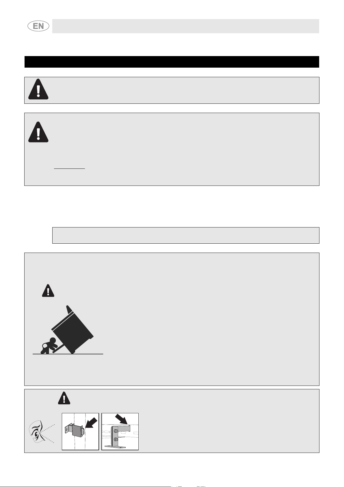
TIP OVER HAZARD
- A child or adult can tip the range and be killed.
- Install the anti-tip device on the structure and/or range fastening the
WARNING
wall-mounted brackets (primary system) or the floor-mounted bracket
(secondary system).
- Fasten the range to the anti-tip device inserting the wall-mounted
brackets into the appropriate hooks on the rear of the range (primary
system) or inserting the floor-mounted bracket (secondary system) into
the central slot on the rear of the range.
- Re-engage the range to the anti-tip device if the range is moved.
- See installation instructions for details.
- Failure to do so can result in death or serious burns to children or
adults.
WARNING
4
PRIMARY FASTENING SYSTEM:
Visually check that the wall-mounted brackets are inserted into the
appropriate lateral hooks (on both sides).
SECONDARY FASTENING SYSTEM:
Visually check from the inside of the drawer that the floor-mounted
bracket anchors the slot on the rear of the range.
Page 3
Important Safety Instruction
- If the information in this manual is not followed precisely, a fire or
explosion may result causing property damage, personal injury or loss
of life.
WARNING
NOTE: This range is manufactured for use with Natural Gas. To convert to LP/Propane gas, see
instructions in the Gas Conversion Kit provided with the appliance literature.
A proper gas supply line must be available. See "Gas supply requirements”.
In the State of Massachusetts, the following installation instructions apply:
- All installation and repairs must be performed by a qualified contractor, plumber, or gasfitter duly
approved or licensed by the State of Massachusetts.
- If using a ball valve, it shall be the “T”-handle type.
- A flexible gas connector, if used, must not exceed 3 feet.
NOTE: This range is NOT designed for installation in manufactured (mobile) homes or in recreational
vehicles.
- Disconnect the power before installing. Before turning power ON, be
sure that all controls are in the OFF position.
- Do not store or use gasoline or other flammable vapors, liquids or
materials near this or any other appliance.
DO NOT install this range outdoors.
WARNING
- Read all instructions
- Proper installation is your responsibility. Have a qualified technician install and ground this appliance,
in accordance with these installation instructions.
- It is the responsibility of the installer to comply with the installation clearances specified on the
model/serial ID plate. This plate is visibly positioned in the oven door frame and must not be
removed.
CAUTION: To eliminate the risk of burns or fire caused by reaching over hot surface units, storage
cabinets installed above the surface unit should be avoided.
To reduce the risk of fire, electrical shock, personal injury or damage when
installing the range, a few basic precautions must be followed, including:
5
Page 4
Instructions for the Installer
- ELECTRICAL GROUNDING REQUIRED: See the “Electrical Connection” section. It is the
customer’s responsibility and obligation:
1 To contact a qualified electrician to install the appliance
2 To ensure that the electrical system is adequate and in conformance with the National ANSI/
NFPA 70 ELECTRICAL CODE – latest edition – or CSA STANDARDS C22.1-94, CANADIAN
ELECTRICAL CODE, PART 1 AND CSA C22.2 No. O-91 – or latest edition – and all local codes
and regulations. IMPORTANT: Observe all governing codes and ordinances.
- Before you plug in the electrical cord, make sure that all the controls are in the OFF position.
- Never modify or alter the construction of the appliance. For example, do not remove leveling legs,
panels, ground wire or anti-tip brackets/screws.
CAUTION: This unit is designed as a cooking appliance. As a safety precaution, never use the
appliance for warming or heating a room.
- Do not obstruct ventilation openings and heat exhaust slits.
- Test the appliance immediately after installation, following the instructions in this booklet. If the
appliance does not work properly, disconnect it from the electrical power supply and call the
technical assistance center. DO NOT attempt to repair the appliance.
- All adjustments and servicing must be performed only by qualified installers or service technicians.
- Do not leave appliance packaging around the home. Separate the various waste materials and take
them to the nearest specialized waste collection facility.
THE SERIAL PLATE WITH TECHNICAL DATA, SERIAL NUMBER AND BRAND NAME IS
POSITIONED VISIBLY INSIDE DRAWER UNDER THE OVEN.
THE SERIAL PLATE MUST NOT BE REMOVED.
- This appliance is intended for use in the home only.
- Use this appliance only for its intended purpose. The manufacturer cannot be
held responsible for damage caused by improper use of this range.
WARNING
- This appliance complies with current safety requirements. Improper use of the
appliance can lead to personal injury and property damage.
- Read all the instructions before installing or using the range for the first time.
- Keep these operating instructions in a safe place and pass them on to the
next user.
SAVE THESE INSTRUCTIONS
6
Page 5
Instructions for the Installer
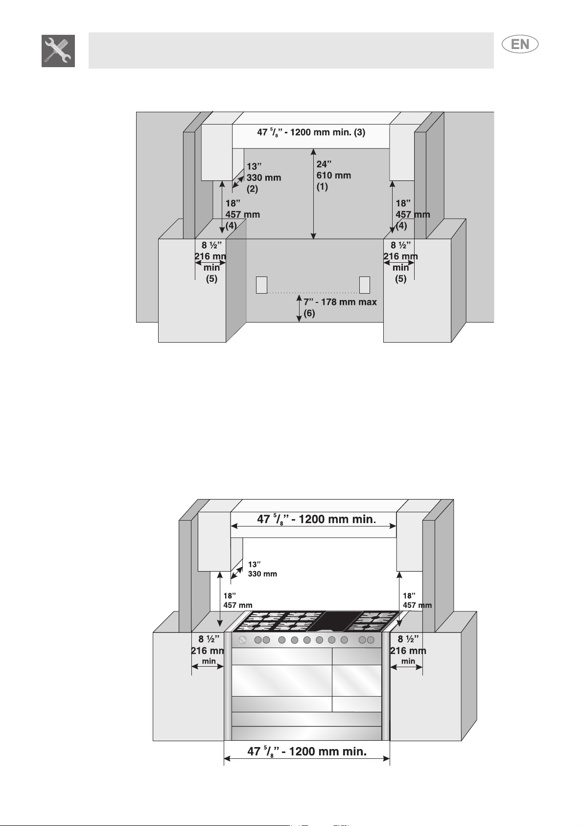
2. DIMENSIONAL REQUIREMENTS
1 24” (61 cm) min. when bottom of wood or metal cabinet is protected by not less than ¼” (0.64 cm)
flame retardant millboard covered with not less than No. 28 MSG sheet steel, 0.015” (0.4 mm)
stainless steel, 0.024” (0.6 mm) aluminum or 0.020” (0.5 mm) copper. When installed in a 24” (61 cm)
base cabinet with 25” (63.5 cm) countertop – the front of the oven door protrudes 1-7/8” (4.8 cm)
beyond the 24” (61 cm) base cabinet. 30” (76.2 cm) min. clearance between the top of the cooking
surface and the bottom of an unprotected wood or metal cabinet;
2 13” (33 cm) max. upper cabinet depth;
5
347
4 18” (45.7 cm) overhead cabinet to countertop;
58
6 7” (17,8 cm) max. junction box.
/8” (1200 cm) min. cabinet opening width;
1
/2” (21,6 cm) min. clearance from the sides of range to adjacent side wall or other combustible
material;
7
Page 6
Instructions for the Installer
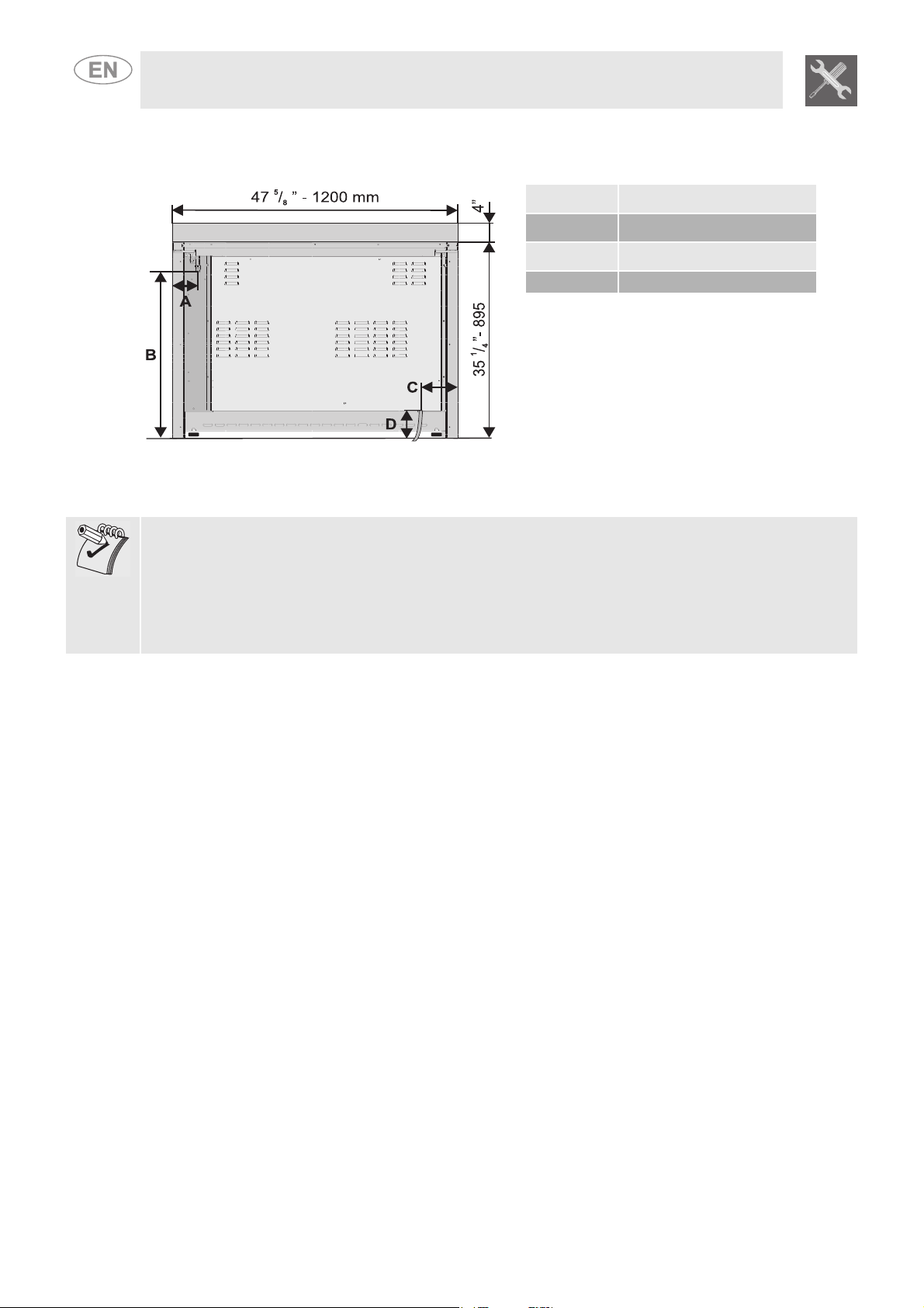
2.1 Product dimensions
Overall dimensions: location of electrical connection points.
A
B
C
D 127 mm - 5”
Check the location where the range is to be installed. The range should be positioned conveniently in the
kitchen.
NOTE: Observe all governing codes and ordinances.
All openings in the wall or floor where range is to be installed must be sealed.
Some cabinet and building materials are not designed to withstand the heat produced by the oven for
baking. Check with your builder or cabinet supplier to make sure that the materials used will not discolor,
delaminate or sustain other damage.
107 mm - 4 1/4 “
759 mm - 29 7/8 “
155 mm - 6 1/8”
The cabinet dimensions shown must be used. The distances shown are minimum clearances.
When installing a range under existing cabinets and the configuration does not satisfy the minimum
cabinet clearances, install a range hood above the rangetop to avoid burn hazards.
8
Page 7

Instructions for the Installer
3. UNPACKING, MOVING AND POSITIONING THE RANGE
CAUTION: This unit is designed as a cooking appliance. As a safety precaution, the appliance should
never be used to warm or heat a room.
- It is recommended to remove grates, griddle plates, burner heads, burner caps, front kick plate and
oven racks be removed to facilitate lifting and handling. This will reduce the weight when moving.
- Remove the outer carton and packing material from the shipping base.
- Remove angle-mounting brackets from the range.
- Because of the weight, a dolly/hand truck with soft wheels should be used to move this unit. The
weight must be supported uniformly across the bottom.
- After transporting the professional range close to its final location, the range can be tipped back and
supported on the rear legs while the dolly is carefully removed.
The floor under the legs should be protected (using wood, strips, carpet, paneling and the
like) before pushing the unit into position.
The anti-tip device must be installed, gas and electrical connections should be made before
the range is placed in its final position.
- For satisfactory performance, the professional range must be leveled. The range is leveled by
adjusting the four leveling legs provide the appliance with perfectly level plane. To do this, loosen the
lock nut and unscrew the foot. The adjustment range of the leveling legs is 10mm.
- Ensure that the burner caps are correctly positioned on the burner heads of the range’s cooktop.
9
Page 8

Instructions for the Installer
4. WALL ATTACHMENT AND THE ANTI-TIP DEVICE
TIP OVER HAZARD
- A child or adult can tip the range and be killed.
- Install the anti-tip device on the structure and/or range fastening the
WARNING
wall-mounted brackets (primary system) or the floor-mounted bracket
(secondary system).
- Fasten the range to the anti-tip device inserting the wall-mounted
brackets into the appropriate hooks on the rear of the range (primary
system) or inserting the floor-mounted bracket (secondary system) into
the central slot on the rear of the range.
- Re-engage the range to the anti-tip device if the range is moved.
- See installation instructions for details.
- Failure to do so can result in death or serious burns to children or
adults.
WARNING
WARNING
ELECTRICAL SHOCK HAZARD
- Use extreme caution when drilling holes into the wall or floor. There may be
concealed electrical wires located behind the wall or under the floor.
- Locate any existing wiring that could be affected by the installation of the AntiTip Device, then turn off the power to these circuits.
PRIMARY FASTENING SYSTEM:
Visually check that the wall-mounted brackets are inserted into the
appropriate lateral hooks (on both sides).
SECONDARY FASTENING SYSTEM:
Visually check from the inside of the drawer that the floor-mounted
bracket anchors the slot on the rear of the range.
- Failure to follow these instructions may result in electrical shock or other
personal injury.
CAUTION: PROPERTY DAMAGE
- Contact a qualified installer or contractor to determine the proper method for drilling holes through the
walls or floors (such as ceramic tile, hardwood, etc.)
10
- Failure to follow these instructions may result in damage to the wall or floor.
Page 9

Instructions for the Installer
4.1 Tools required for installing the Anti-Tip Device:
- Ruler or tape measure - Flat tip screwdriver
- Philips screwdriver - Gloves
- Pliers - 3/8” rachet wrench
- Safety glasses - Wrench
4.2 Instructions for wall mounting (primary system)
Secure the anti tip brackets to the rear wall as shown. The height from the floor for anchoring the bracket
is determined after the range legs have been adjusted to the proper installation height as shown in the
installation instructions and the range has been leveled.
1 Level the range
using the front
adjustable leveling
legs.
3 Attach the two anti-tip brackets to the wall
using an appropriate fastener (for example,
screws appropriate for the type of wall).
Adhere carefully to the dimensions shown in
Figures (A) using the appliance’s dimensions
as a guide. (Type of screw recommended:
”).
4
2 From the floor,
measure the
height of the
notch found on
the bracket.
This notch
corresponds to
the centerline
of the holes for
the screws that
will fasten the
brackets to the
wall.
1
/
11
Page 10

Instructions for the Installer
A3XU6 (47
4 Correctly position the range so that the two
brackets anchored in the wall fit the anti-tip
brackets on the range perfectly.
5
/8 ” - 1200 mm)
A)
12
Page 11

Instructions for the Installer
4.3 Instructions for floor mounting (secondary system)
The secondary anti-tip device is to be attached to the floor when it is not possible to install the primary
system. After having positioned and leveled the appliance the bracket has to be anchored to the floor
and engaged in the slots at the rear of the appliance.
NOTE: According to the type of floor, the installer should supply the suitable fastening systems (Type of
3
screw recommended
/8”).
1 After positioning and leveling the appliance, place the fastening bracket near it and anchor it to the
floor according to the indicated distances.
2 Assemble the fastening bracket as shown in
the figure. Join the two parts without tightening
them too much since there will be other
adjustments to make.
3 Lower the bracket attachment until anchoring
the appliance slot, tighten the nuts previously
assembled. The anti-tip device works properly
only if the bracket attachment is securely
anchored to the appliance.
13
Page 12

Instructions for the Installer
4.4 Mounting the rear rangetop backguard
1 Position the backguard on the rangetop, so that holes A and B are aligned.
2 Secure the backstop to the rangetop by tightening screws C.
14
Page 13

Instructions for the Installer
5. MAKING THE ELECTRICAL CONNECTION
ELECTRICAL SHOCK HAZARD
- Disconnect power to the junction box before making the electrical
connection
WARNING
Make sure that the power supply rating matches the specifications indicated on the model/serial plate
located on the oven door frame.
Never remove this plate.
If codes permit and a separate ground wire is used, it is recommended that a qualified electrician
determine whether the ground path is adequate.
When a four-wire or three-wire, single-phase, 120/208-volt, 60 Hz or 120/240-volt, 60 Hz, AC-only,
electrical supply is available, a 20 ampere maximum circuit protection is required. A time-delay fuse or
circuit breaker is recommended. The serial plate is located on the oven door frame.
Wire size and connections must conform to the requirements of the National Electrical Code, ANS/NFPA
70 ELECTRICAL CODE (*) – last edition or CSA Standard C22.1-94, Canadian Electrical code, Part 1
(**) and CSA C22.2 No. O-91 or latest edition and all local codes and regulations for the kilowatt rating of
the range. IMPORTANT: Observe all governing codes and ordinances.
Copies of the standards listed may be obtained from:
(*) National Fire Protection Association, Batterymarch Park, Quincy, Massachusetts 02269 USA;
(**) Canadian Standards Association, 5060 Spectrum Way, Mississauga, Ontario L4W 5N6 CANADA
- Electrically ground the appliance with green or green-yellow colored
wire
- Do not ground to a gas pipe
- Check with a qualified electrician if you have any doubt as to whether
the range is grounded
- Do not put a fuse on the neutral or ground circuit
FAILURE TO FOLLOW THESE INSTRUCTIONS COULD RESULT IN LOSS OF
LIFE, FIRE OR ELECTRICAL SHOCK.
This appliance is manufactured with a yellow-green or green ground wire connected to the appliance
chassis. Make sure that the power has been turned off, then connect the flexible cable. Connect the
appliance to the junction box using a UL-listed wire connector (see Figures 1 and 2 on pages 14-15). Do
not shorten the flexible metal cable.
Figure 1 and Figure 2 on pages 16 - 17 and the instruction provided below present the conventional way
of connecting the appliance.
Your local codes and ordinances, of course, take precedence over these instructions. Complete
electrical connections according to local codes and regulations.
This range must be connected to a grounded, metallic, permanent wiring system; a ground connector
should be connected to the ground terminal or wire lead on the appliance.
Connections in the junction box must be made using copper wire only.
15
Page 14

Instructions for the Installer
NOTE: Use this method only if local codes allow connecting the appliance chassis ground conductor to
the neutral wire of the power supply
WAR NIN G
ELECTRICAL SHOCK HAZARD
- Turn the power supply off before connecting wires.
WARNING
- Electrically ground the appliance.
- Failure to follow these instructions can results in loss of life, fire, or
electrical shock.
- Improper connection of the appliance’s grounding conductor can result
in a risk of electrical shock. Check with a qualified electrician or service
technician if you are in doubt as to whether the appliance is properly
grounded. Do not modify the appliance’s power cord. If it does not fit in
the receptacle, have a suitable outlet installed by a qualified electrician.
5.1 Installation in the United States only/3-wire grounded junction box
Refer to Figure 1, where local codes allow the
connection of the appliance chassis grounding
conductor to the power supply cable neutral wire
(white wire):
- The ground wire must be connected first.
- If local codes permit, connect the green or
yellow-green ground wire and the neutral white
wire from the appliance cable to the supply
cable neutral wire (white wire).
- Connect the red and black wires of the
appliance cable using UL-listed or CSAapproved wire connectors to the matching
power supply cables in the junction box.
UL-listed
CSAapproved
wire
(Fig. 1)
16
Page 15

Instructions for the Installer
5.2 Installation in the United States and Canada/4-wire grounded junction box
Refer to Figure 2,
- Separate the green or yellow-green wires from
the white wires that extend out of the end of the
appliance cable.
- The grounding wire must be connected first.
- Connect the green or yellow-green grounding
wire from the appliance cable to the grounded
lead in the junction box (green wire) using ULlisted or CSA-approved wire connectors. Do not
connect the appliance chassis ground wire to
the neutral wire in the junction box.
UL-listed
CSAapproved
wire
- Connect the red and black wires of the
appliance cable to the matching color wires in
the junction box using UL-listed or CSAapproved wire connectors.
- Connect the white wire from the appliance to the
neutral white wire in the junction box using a ULlisted or CSA-approved wire connector.
Connect to a 20A fuse or circuit breaker. Connect to copper wire or, if connection is made to aluminum
house wiring, use UL-listed or CSA-approved connectors that are approved for joining aluminum and
copper wires.
NOTE: Both cables from the range must be connected according to the diagrams shown in Figures 1
and 2.
Fig. 2)
17
Page 16

Instructions for the Installer
6. GAS SUPPLY REQUIREMENTS
EXPLOSION HAZARD
- Use a new AGA design certified or CSA-approved gas connectors.
- Install a shut-off valve.
1)
2)
WARNING
NOTE:
- Observe all governing codes and ordinances.
- The range must be connected to a reliable gas supply.
This installation must conform to local codes and regulations. In the absence of local codes, installations
must conform to American National Standards, National Fuel Gas Code ANSI Z223.1 - latest edition** or
CANI 13149.1 or 2**.
If local codes permit, a flexible metal appliance connector with the new AGA or CSA design, 4-5 feet
(1.2-1.5 m) long, 1/2" or 3/4" I.D., is recommended for connecting this range to the gas supply line.
Do not bend or damage the flexible connector when moving the range. The pressure regulator has 3/8"
female pipe threads. You will need to determine the fittings required, depending on the size of your gas
supply line, the flexible metal connector and the shut-off valve.
- Securely tighten all gas connections.
- lf connected to LP gas, have a qualified technician ensure that the gas
inlet pressure does not exceed a 14" water column.
- Examples of qualified technicians include licensed heating service
personnel, authorized gas company employees, and authorized service
technicians.
- Failure to do so can result in loss of life, explosion, or fire.
3)
Always use a pipe-joint sealant made for use with NATURAL
GAS and L.P. GAS on the joint between pressure regulator D
and the NPT adaptator C and between pressure regulator D and
pipe E. If a flexible metal connector is used, make sure that the
tubing is not kinked.
Use only pipes (E) conforming to codes and regulations in force,
inserting a gasket B (supplied) between fitting A and adaptator
C.
Always place a suitable sealing medium (such as Teflon tape) on
the joint between the pressure regulator D and the adaptator C
and between the pressure regulator D and the pipe E.
WARNING: The tightening torque of adaptor (C ) must not be greater than 36 ozf - 10 Nm.
18
Page 17

3)
4)
Instructions for the Installer
The gas supply line must be fitted with an approved manual
shut-off valve.
This valve should be located in the same room as the appliance
and in a place that allows convenient access for opening and
closing.
Do not block access to the manual shut-off valve. The valve is
necessary for turning the gas to the appliance on or off.
The inlet pressure to the
regulator must be at least 1
inch (2.5 cm) higher than the
manifold pressure. The inlet
pressure to the regulator should
be as follows to operate and
check the regulator:
- NATURAL GAS: manifold
pressure 4” W.C.P. Supply
pressure 3.5”-10.5” W.C.P.
- LP GAS: manifold pressure
11.0” W.C.P. Supply pressure
8.0” - 13” W.C.P.
5)
Line pressure testing: testing above 112 PSI (3.5 kPa), with water column of 14” (35.6 cm) (gauge).
The appliance and its individual shut-off valve must be disconnected from the gas supply line during
pressure testing of that system at test pressures in excess of 1/2 psig (3.5 kPa).
Testing below 112 PSI (3.5 kPa) with a water column of 14” (35.6 cm) (gauge) or lower.
The appliance must be disconnected from the gas supply line by closing its individual shut-off valve
during any pressure testing of that system at test pressures equal to or less than 1/2 psig (3.5 kPa).
19
Page 18

THIS PAGE INTENTIONALLY LEFT BLANK
 Loading...