

Page 1

Contents
1. INSTRUCTIONS FOR SAFE AND PROPER USE________________ 4
2. INSTALLATION OF THE APPLIANCE_________________________ 6
3. ADAPTATION TO DIFFERENT TYPES OF GAS _______________ 12
4. FINAL OPERATIONS_____________________________________ 14
5. DESCRIPTION OF CONTROLS ____________________________ 15
6. USE OF THE COOKING HOB ______________________________ 21
7. USE OF THE OVENS_____________________________________ 23
8. ACCESSORIES _________________________________________ 24
9. COOKING HINTS________________________________________ 26
10. CLEANING AND MAINTENANCE ___________________________ 34
11. EXTRAORDINARY MAINTENANCE _________________________ 38
12. PROBLEMS AND CAUSES ________________________________ 41
INSTRUCTIONS FOR THE INSTALLER: these are for the qualified
technician who must carry out a suitable check of the gas system,
install the appliance, set it functioning and carry out an inspection test.
INSTRUCTIONS FOR THE USER: these contain user advice,
description of the commands and the correct procedures for cleaning
and maintenance of the appliance.
3
Page 2
Introduction
1. INSTRUCTIONS FOR SAFE AND PROPER USE
THIS MANUAL IS AN INTEGRAL PART OF THE APPLIANCE AND
THEREFORE MUST BE KEPT IN ITS ENTIRETY AND IN AN ACCESSIBLE
PLACE FOR THE WHOLE WORKING LIFE OF THE COOKER. WE ADVISE
READING THIS MANUAL AND ALL THE INSTRUCTIONS THEREIN BEFORE
USING THE COOKER. ALSO KEEP THE SERIES OF NOZZLES SUPPLIED.
INSTALLATION MUST BE CARRIED OUT BY QUALIFIED PERSONNEL IN
ACCORDANCE WITH THE REGULATIONS IN FORCE. THIS APPLIANCE IS
INTENDED FOR DOMESTIC USES AND CONFORMS TO CURRENT
REGULATIONS IN FORCE. THE APPLIANCE HAS BEEN BUILT TO CARRY
OUT THE FOLLOWING FUNCTIONS: COOKING AND HEATING-UP OF FOOD.
ALL OTHER USES ARE CONSIDERED IMPROPER.
THE MANUFACTURER DECLINES ALL RESPONSIBILITY FOR IMPROPER
USE.
DO NOT LEAVE THE PACKING IN THE HOME ENVIRONMENT. SEPARATE
THE VARIOUS WASTE MATERIALS AND TAKE THEM TO THE NEAREST
SPECIAL GARBAGE COLLECTION CENTRE.
IT IS OBLIGATORY FOR THE ELECTRICAL SYSTEM TO BE GROUNDED
ACCORDING TO THE METHODS REQUIRED BY SAFETY RULES.
IMMEDIATELY AFTER INSTALLATION CARRY OUT A BRIEF INSPECTION
TEST OF THE APPLIANCE, FOLLOWING THE INSTRUCTIONS BELOW.
SHOULD THE APPLIANCE NOT FUNCTION, SWITCH OFF THE POWER
SUPPLY TO THE APPLIANCE AND CALL THE NEAREST TECHNICAL
ASSISTANCE CENTRE.
NEVER ATTEMPT TO REPAIR THE APPLIANCE.
ALWAYS CHECK THAT THE CONTROL KNOBS ARE IN THE POSITION
(OFF) WHEN YOU FINISH USING THE HOB.
NEVER PUT INFLAMMABLE OBJECTS INTO AN OVEN: IF THEY CATCH FIRE
THEY COULD CAUSE A FIRE IN THE HOME.
THE I.D. PLATE WITH TECHNICAL DATA, REGISTRATION NUMBER AND
BRAND NAME IS POSITIONED VISIBLY IN THE STORAGE COMPARTMENT.
THE PLATE MUST NOT BE REMOVED.
DURING USE THE APPLIANCE BECOMES VERY HOT. TAKE CARE NOT TO
TOUCH THE HEATING ELEMENTS INSIDE THE OVEN.
4
Page 3
Introduction
DO NOT INSTALL THIS APPLIANCE ON A RAISED PLATFORM
DO NOT PUT PANS WITHOUT PERFECTLY SMOOTH AND FLAT BOTTOMS
ON THE COOKING HOB GRIDS.
DO NOT USE CONTAINERS OR BROILERS THAT EXTEND BEYOND THE
OUTER PERIMETER OF THE HOB.
THE APPLIANCE IS DESIGNED FOR USE BY ADULTS. DO NOT ALLOW
CHILDREN TO GO NEAR OR PLAY WITH IT.
THIS APPLIANCE IS MARKED ACCORDING TO THE EUROPEAN DIRECTIVE
2002/96/EC ON WASTE ELECTRICAL AND ELECTRONIC EQUIPMENT
(WEEE).
THIS GUIDELINE IS THE FRAME OF A EUROPEAN-WIDE VALIDITY OF
RETURN AND RECYCLING ON WASTE ELECTRICAL AND ELECTRONIC
EQUIPMENT.
BEFORE THE APPLIANCE IS PUT INTO OPERATION, ALL THE LABELS AND
PROTECTIVE FILMS APPLIED INSIDE OR OUTSIDE MUST BE REMOVED.
THIS APPLIANCE IS DESIGNED FOR COOKING FOOD AND IT SHALL NOT
BE USED AS A SPACE HEATER.
DO NOT SPRAY AEROSOLS IN THE VICINITY OF THIS APPLIANCE WHILE IT
IS IN OPERATION.
The manufacturer declines all responsibility for damage to persons
or things caused by non-observance of the above prescriptions or by
interference with any part of the appliance or by the use of non-original
spares.
5
Page 4
Instructions for the installer
2. INSTALLATION OF THE APPLIANCE
It is the law that all gas appliances are installed by authorised persons.
Clearance around the cooker must comply with the requirements of
AS5601.
2.1 Positioning and levelling of the appliance
This appliance is fitted with 4 castors for easy positioning. To block the
appliance in tis final position, extract the feet on the front and screw the
corresponding castors in.
CAUTION: delicate floors could be damaged by the castors; in this case,
2.2 Electrical connection
Make sure that the power line voltage matches the specifications
indicated on the rating plate located inside the storage compartment.
This rating plate must never be removed.
The connection to the mains shall be done conforming to the regulations
in force. Check that the power line is adequately grounded. Do not use
reducers, adapters or shunts. On the power line, install an omnipolar cutoff device with contact cut-off distance greater than or equal to 3 mm,
located in an easily accessible position near the unit.
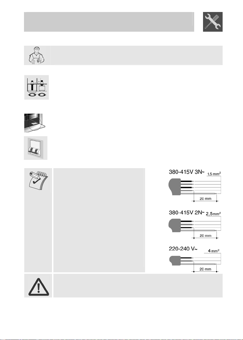
For operation on 400-415V3N∼: use
an H05RR-F-type five-core cable (5 x
1.5 mm2).
For operation on 400-415V2N∼: use
an H05RR-F-type four-core cable (4 x
2.5 mm2).
For operation on 230-240V∼: use an
H05RR-F-type three-core cable (3 x 4
mm2).
The cable end to be connected to the
appliance must be provided with an
ground wire (yellow-green) at least 20
mm longer.
The manufacturer declines all responsibility for damage to persons
or things caused by non-observance of the above prescriptions or by
interference with any part of the appliance.
lift the appliance with a mechanical means.
6
Page 5
Instructions for the installer
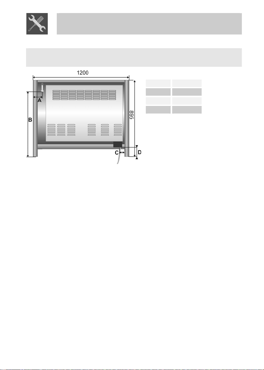
Overall dimensions: location of gas and electrical connection points (all
measures in mm).
A 110
B 770
C 150
D 170
7
Page 6
Instructions for the installer
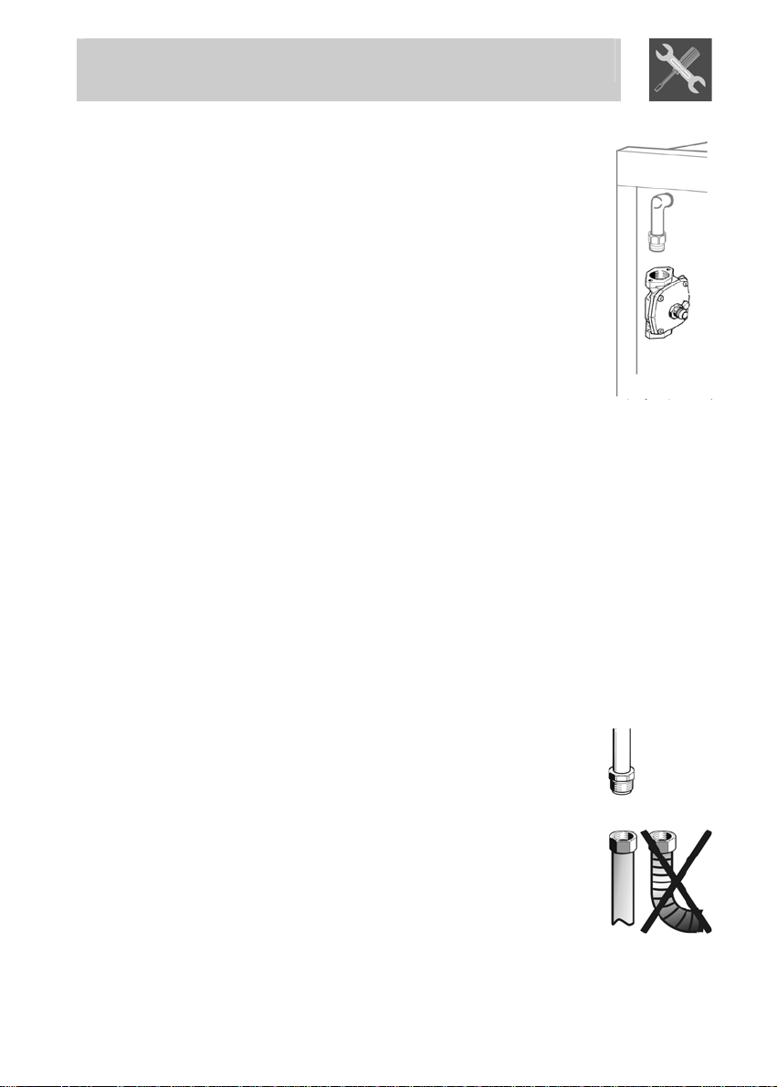
2.3 Gas connection
This appliance is suitable for installation with Natural
Gas or LPG (propane). Refer to page 12 for the relevant
burner pressure and appropriate injector sizes. When
the appliance is to be connected to Natural Gas then the
pressure regulator supplied must be fitted to the gas
inlet. A test point (for checking the gas pressure) is
supplied either with the regulator or as a separate fitting
in the case of LPG (propane) appliances.
Connection of the appliance to the gas supply must be in
accordance with the requirements of AS5601. A ½” BSP
connector at the inlet is recommended and the gas
supply line to the appliance must be of adequate length
to allow sufficient withdrawal of appliance for service or
disconnection and be annealed copper pipe.
The cooker must be installed with provision to allow the gas to be turned
off and disconnected for servicing and removal of the appliance as
required from the gas supply.
Before the cooker is operated make certain all relevant parts are placed
in the correct position.
When the installation is completed the installation connections of cooker
will require to be leak tested, the burner operating pressure and flame
checked and adjusted.
Warranty service calls do not cover these adjustments!
To check the operating pressure of the appliance it is recommended at
least 2 large size burners are used. Ensure appliance is secured to wall
when installation is completed.
N.G. The regulator supplied must be fitted to the ½ BSP thread at the
rear of the appliance. An approved manual shut-off valve must be
installed. The N.G. regulator must be checked and adjusted to 1.0kPa
after installation.
L.P.G. Can be connected to the inlet fitting directly. The
pressure must be checked to ensure it is operating at
2.75kPa. A separate test point fitting must be installed
between the piping & the appliance for the pressure to
be checked to ensure it is operating at 2.75kPa.
8
Page 7
Instructions for the installer
2.4 Room ventilation
Caution – This cooker may only be installed and operated in rooms
permanently ventilated in accordance with current regulations. For
proper operation of a gas appliance it is essential for the air necessary
for combustion of the gas to be able to flow naturally into the room. Air
must flow directly into the room through openings in its outside walls.
This (these) opening (s) must have a free passage cross-section of at
least 100 cm2, or 200 cm2 for appliances not equipped with gas safety
device. These openings must be constructed so that they cannot be
obstructed indoors or outdoors, and should preferably be close to the
floor on the side opposite to the combustion gas discharge point. If it is
not possible to make the openings in the room where the cooker is
installed, the necessary air may be taken from an adjoining room,
proveded it is not a bedroom or a room with fire risk.
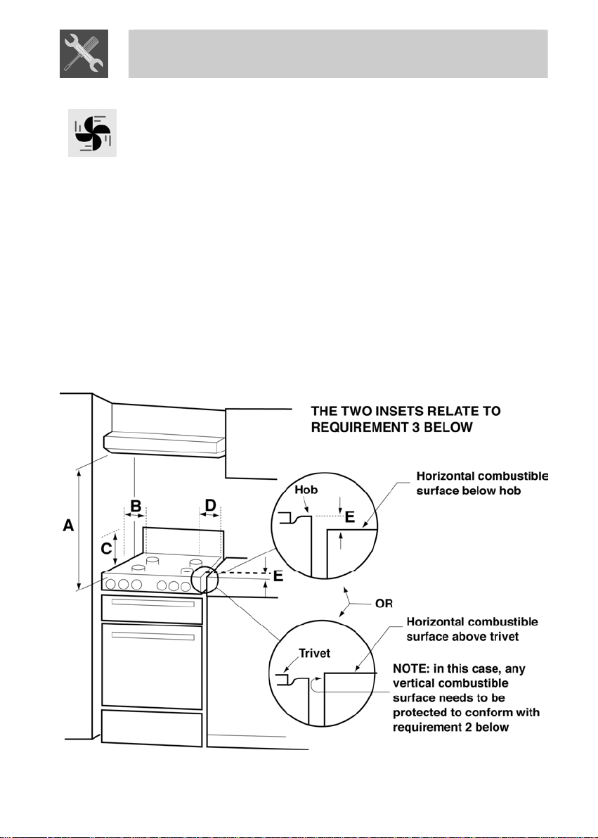
2.5 Clearance above and around domestic cookers
Extract from AS5601
9
Page 8

Instructions for the installer
REQUIREMENTS
1 Overhead clearances – (Measurement A)
Range hoods and exhaust fans shall be installed in accordance with
the manufacturer’s instructions. However, in no case shall the
clearance between the highest part of the hob of the cooking
appliance and a range hood be less than 600 mm or, for an overhead
exhaust fan, 750 mm.
Any other downward facing combustible surface less than 600 mm
above the highest part of the hob shall be protected for the full width
and depth of the cooking surface area in accordance with Clause
5.12.1.2. However, in no case shall this clearance to any surface be
less than 450 mm.
2 Side clearances – (Measurements B & C)
Where B, measured from the periphery of the nearest burner to any
vertical combustible surface, is less than 200 mm, the surface shall
be protected in accordance with Clause 5.12.1.2 to a height C of not
less than 150 mm above the hob for the full dimension (width or
depth) of the cooking surface area. Where the cooking appliance is
fitted with a ‘splashback’, protection of the rear wall is not required.
3 Additional requirements for Freestanding and Elevated Cooking
Appliaces – (Measurements D & E)
Where D, the distance from the periphery of the nearest burner to a
horizontal combustible surface is less than 200 mm, then E shall be
10 mm or more, or the horizontal surface shall be above the
See insets above.
NOTES
1 Requirement 3 does not apply to a freestanding or elevated
cooking appliance which is designed to prevent flames or the
cooking vessels from extending beyond the periphery of the
appliance.
2 The ‘cooking surface area’ is defined as that part of the
appliance where cooking normally takes place and does not
include those parts of the appliance containing control knobs.
3 For definition of hob, see Clause 1.4.64.
4 For definition of trivet, see Clause 1.4.109.
5 Consideration is to be given to window treatments when
located near cooking appliances. See Clause 5.3.4.
trivet.
10
Page 9
Instructions for the installer
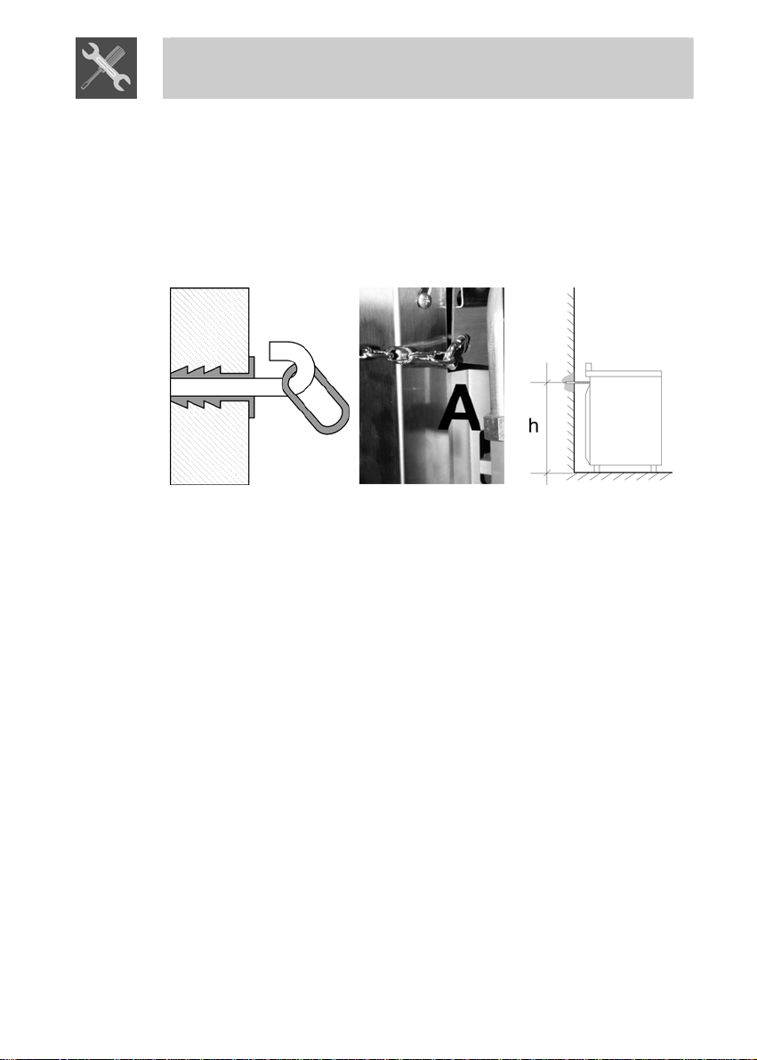
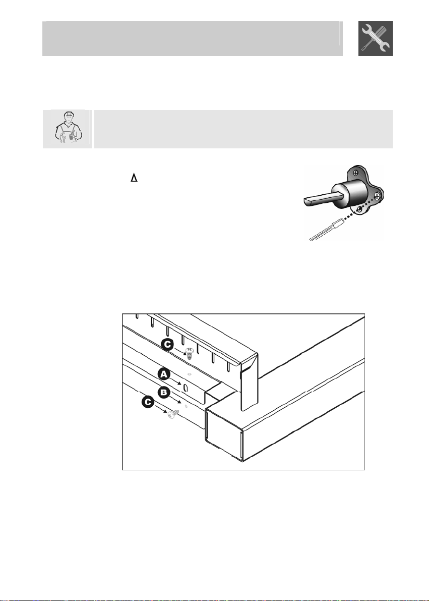
2.6 Instruction for wall fixing
1) Fix the screw to the wall and hook the chain (B);
2) Hook the chain to the hole positioned at the rear of the cooker by the
gas pipe (A);
3) Once the chain is in position, push the cooker against the wall;
4) The height of the screw hole from floor level must not exceed 800
mm (C).
A
B
C
11
Page 10
Instructions for the installer
3. ADAPTATION TO DIFFERENT TYPES OF GAS
Before performing any cleaning or maintenance work, switch off the
power supply to the appliance.
The cooking hob of the cooker is preset for G20 natural gas at a
pressure of 20 mbar. In the case of functioning with other types of gas the
burner nozzles must be changed and the minimum flame adjusted on the
gas taps. Replace the burner nozzles as indicated in the table of the gas
to be used.
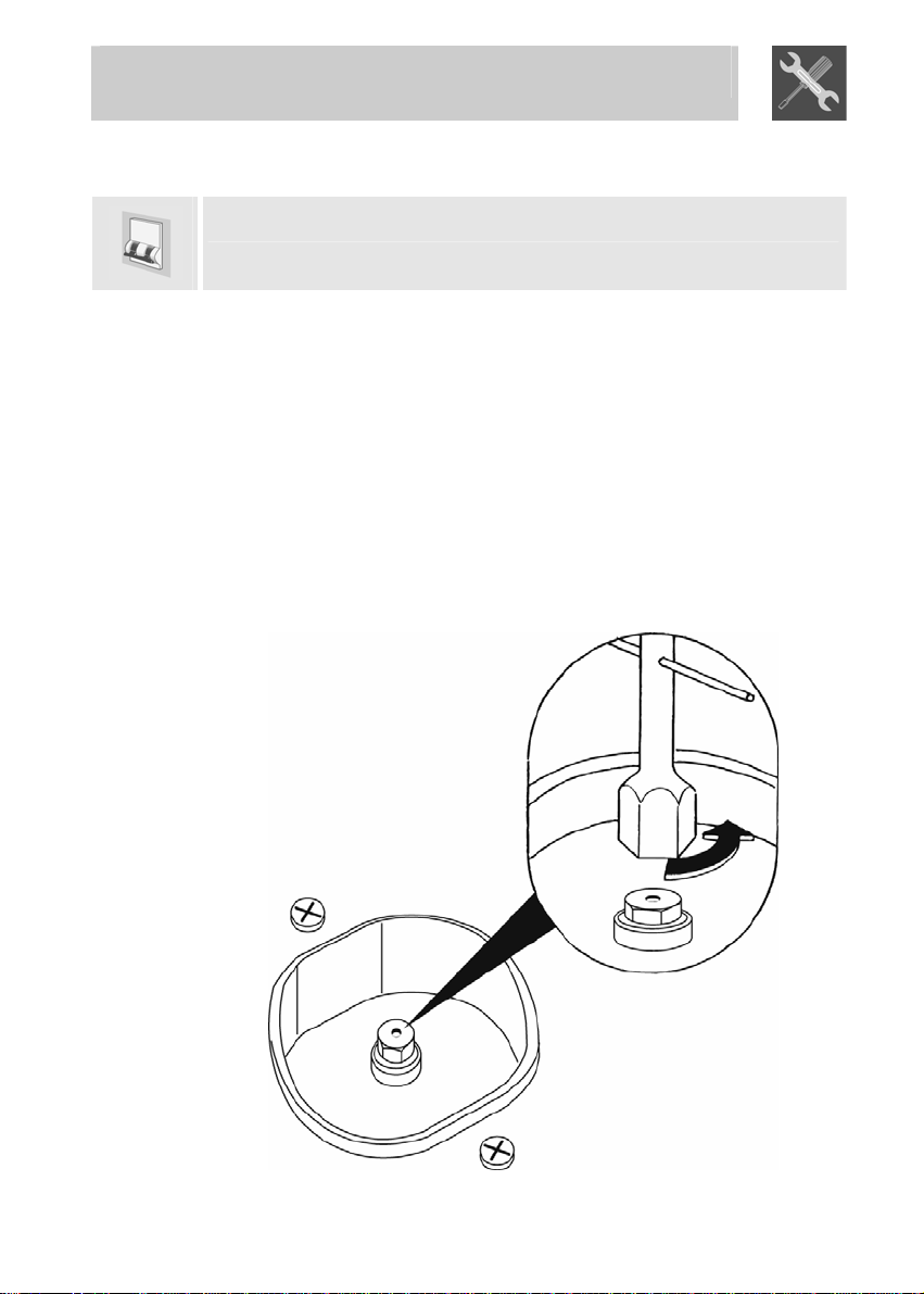
3.1 Changing nozzles
1. Extract the grids and remove all the caps and flame-spreader
crowns;
2. unscrew the burner nozzles with a 7 mm socket wrench;
3. proceed with replacing the burner nozzles in accordance with the
table for the gas in question.
12
Page 11
Instructions for the installer
Burner
Auxiliary 3.9 0.54
Semi rapid 6.3 0.68
Rapid 10.8 0.88
Triple crown 12.8 1.00
Fish pan 6.8 0.72
Burner
Auxiliary 3.7 0.90
Semi rapid 6.5 1.20
Rapid 10.9 1.55
Triple crown 12.7 1.75
Fish pan 7.2 1.25
3.2 Burner and nozzle characteristics table
LPG (PROPANE) – 2.75 KPa
Nominal gas consumption
Nominal gas consumption
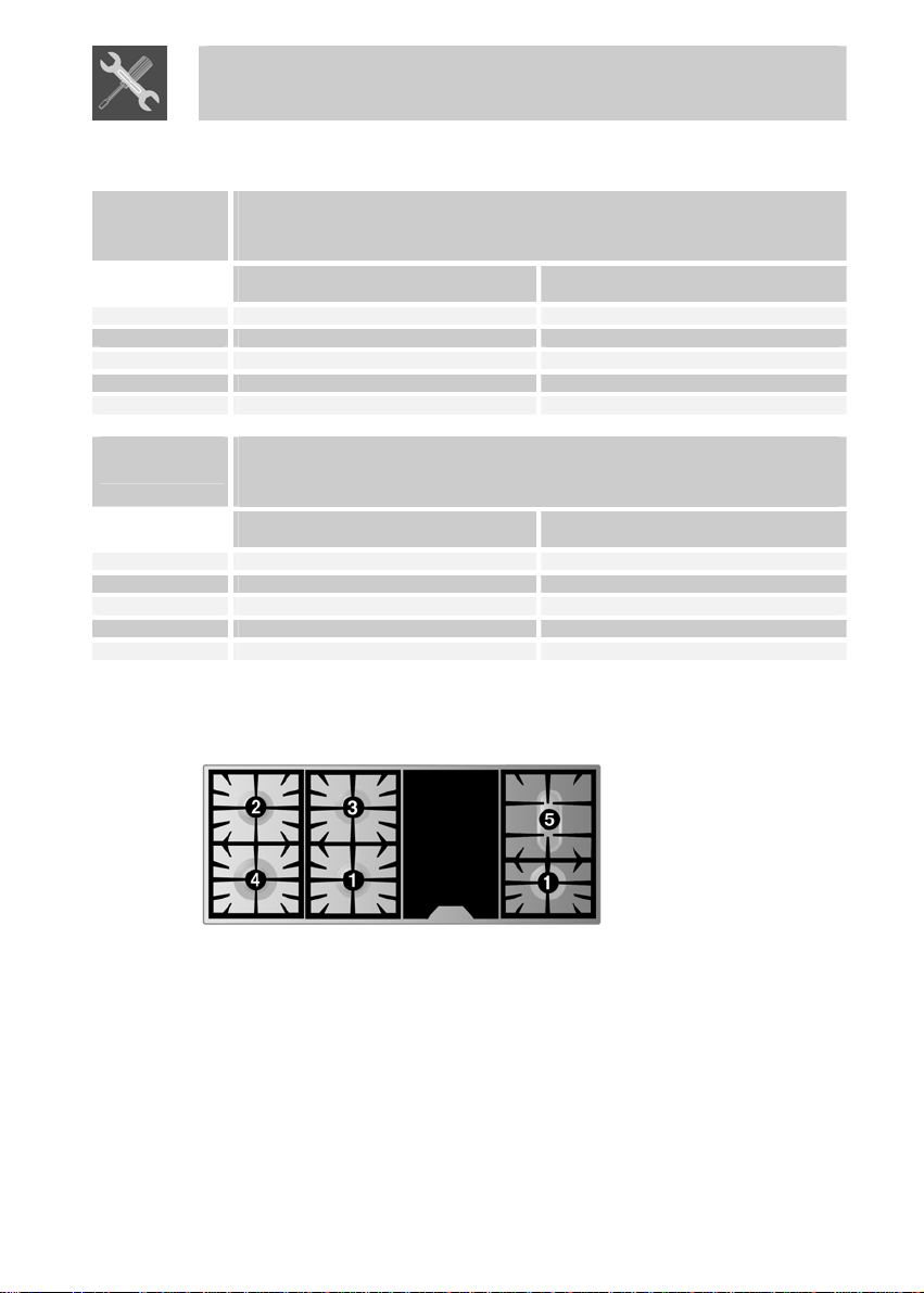
3.3 Arrangement of burners on cooking hob
(MJ/h)
NG – 1.0 KPa
(MJ/h)
Injector
(mm)
Injector
(mm)
BURNERS
1 y
A ruxilia
2 Semi rapid
3 R
apid
4 Triple crown
5 Fish burner
13
Page 12
Instructions for the installer
4. FINAL OP TIONS
After replacing the nozzles, reposition the flame-spreader crowns, the
burner caps and the grids.
Following adjustment to a gas other than the preset one, replace the gas
adjustment label fixed to the appliance with the one corresponding to the
new gas. This label is in the packet together wit . h the nozzles
4.1 Adjustment of minimum for natural gas
Light the burner and turn it to the minimu
position m . Extract the gas tap knob and turn the
adjustment screw at the side of the tap rod un
the correct minimum flame is achieved.
Replace the knob and check burner fl m
stability: (rapidly turning the knob from maximum
to minimum position, the flame should not go
out). Repeat the operation on all the gas taps.
4.2 Mounting the rear top upstand
• Position the upstand above the top, taking care to align holes A with
holes B.
• Secure the upstand to the top by tightening screws C.
ERA
til
a e
14
Page 13

Instructions for the user
5. DESCRIPTION OF CO
5
.1 Front control panel
All the cooker controls and co
NTROLS
mmands are on the front panel.
Before using the main oven check that the electronic programmer is
showing the symbol (see paragraph “5.2.1 Clock adjustment”).
DESCRIZIONE DEI SIMBOLI
FRONT LEFT BURNER
FRONT CENTRAL
BURNER
FRONT RIGHT BURNER
BARBECUE ELEMENT
MAIN OVEN
THERMOSTAT
MAIN OVEN
FUNCTIONS
BACK LEFT BURNER
RAL BACK CENT
BURNER
BACK RIGHT BURNER
AUXILIARY OVEN
THERMOSTAT
AUXILIARY OVEN
FUNCTIONS
COOKING HOB BURNER COMMAND KNOB
The flame is lit by pressing the knob and turning it
anticlockwise to maximum flame . To adjust the
flame turn the knob between um ( maxim ) and
minimum ( ). The burner goes out when the knob is
returned to the position .
15
Page 14

Instructions for the user
MAIN OVEN THERMOSTAT KNOB
Selection of cooking temperature is carried out by
turning the knob clockwise to the required temperature,
between 50° and 250°C.
The tell-tale light comes on to indicate that the oven is
warming up. When it goes out it means that the
required temperature has been reached. Intermittent
going on and off of the light means that the oven
temperature is being constantly maintained at the
programmed level.
AUXILIARY OVEN VARIABLE GRILL KNOB
Position the auxiliary oven thermostat knob on the
symbol or .
Turn the variable grill knob clockwise to the desired
position.
When the signal light comes on the grill is engaged.
BARB ER REGULATECUE ELEMENT POW OR
KNOB
This knob allows adjustment of the power of the
barbecue b. Set the knob griddle on the ho on any
position from “1” to “9” to turn on the heating element.
The pilot lig e at the elemeht illuminates to indicat th nt is
in operation.
To switch off the element, turn the knob to “0”.
CAUTION: after it has been in operation for some time, the plate will
remain hot even after the element has been sw hildren itched off: keep c
at a safe distance.
16
Page 15

Instructions for the user
MAIN OVEN FUNCTION SWITCH KNOB
Turn the knob to select from the following functions:
NO FUNCTION SET
OVEN LIGHT
UPP
ER AND LOWER
HEA E T
TING EL MEN
GRILL ELEMENT
AUXILIARY OVEN THERMOSTAT KNOB
Selection of cooking temperature is carried out by
turning the knob clockwise to the required temperature,
between 50° and 220°C.
The tell-tale light comes on to indicate that the oven is
warming up. When it goes out it means that the
required temperature has been reached. Intermittent
going on and off of the light means that the oven
temperature is being constantly maintained at the
programmed level.
The oven is switched on by turning the knob clockwise
to any one of the following functions except the oven
light:
NO FUNCTION SET
OVEN LIGHT
UPPER AND LOWER HEATING
ELEMENT (between 50° and 220°C)
GRILL ELEMENT +
VENTILA
TION
LOWER HEATING ELEMENT
+ VENTILATED HEATING
ELEMENT
VENTILATED HEATING
ELEMENT
+ VENTILATION
LOWER HEATING ELEMENT
GRILL ELEMENT (spit)
UPPER HEATING ELEMENT
+ GRILL ELEMENT
17
Page 16

Instructions for the user
5.2 Electronic Programmer
The programmer user instructions are valid only for the main oven.
LIST OF FUNCTIONS
MINUTE-COUNTER KEY
COOKING TIME KEY
END-OF-COOKING KEY
DECREASE TIME KEY
INCREASE TIME KEY
5.2.1 Clock adjustment
When usin i fter a power failure, the disp
flashes regularly and indicates
same time the keys
g the oven for the first t me, or a lay
. Press the keys and at the
o : each single pr ess changes the time by 1
minute either up or down.
Before setting the programmer activate the desired function and
temperature.
18
Page 17

Instructions for the user
5.2.2 Semiautomatic cooking
s this setting for automatic oven switch-off at the end of cooking time.
eU
By pressing key
d and at the same time, press keys presse
, the display lights up, showing ; keep the key
o to set the cooking
time.
Release key
to start the programmed cooking time count. The display
will now sho the right time together with symbols A and w
.
5.2.3 Automatic cooking
Use i y start and stop the oven.
th s setting to automaticall
By p
ressing key
presse and at the same time, press keys
, the display lights up showing ; keep the key
or d to set the cooking
time.
By pressing key
keep th t the same time, press keyse key pressed and a
regul
ate the end of cooking time.
Release key
the right time together with symbols A and
After set-up, to see the cooking time remaining, press the key
the sum of the right time + cooking time will appear;
o to
to start the programmed count and the display will show
.
; to see
the end of cooking time press the key .
Set-up with incoherent values is logically prevented (e.g. the contrast
betwe a cooking time anen d a longer period will not be accepted by the
programmer).
5.2.4 End of cooking
When cooking is over, t e ov n will automatically switch off and, at the
same time, an intermittent
e display will once again show the right time together with the symbol
th
h e
alarm will sound. After switching off the alarm,
, indicating that the oven has returned to manual operation mode.
19
Page 18

Instructions for the user
5.2.5 Adjusting alarm volume
The acoustic alarm has three different settings. These can be operated,
while the alarm is sounding, by pressing key
.
5.2.6 Switching off the alarm
The alarm switches off automatically after seven minutes. They can be
manually de-activated by pres
sing the keys
and together
.
5.2.7 Minute Counter
The programmer can also be used as a simpl e counter. By
pressing key
same time press keys
at the
programmed cou ing will begin and the display will show the current
time and the symbol
, the display shows ; keep th
o . On releasing the key ,
nt
.
e minut
e key pressed and
After set-up, to see the remaining time, press the key .
Use as a minute counter does not interrupt ncfu tioning of the oven at the
end of the programmed time.
5.2.8 Cancellation of set data
Once the programme has been set, keep the key of the function to be
cancelled pres
of variation keys
sed, while at the same time
o . Time cancellation will be considered as end-of-
cooking time by the prog
rammer.
is reached by means
5.2.9 Changing the set data
Th the
e cooking data entered can be changed at any time by keeping
nction key pressed and at the same time adjusting the keys
fu
o .
20
Page 19

Instructions for the user
6 G HOB
. USE OF THE COOKIN
6 s
.1 Lighting of the cooking hob burner
Before lighting the cooking hob burners check that the flame cap crowns
are properly positioned with their appropriate burner caps: niche A must
be centred with pin B.
Grid C should be used with Chinese woks.
Each knob c responds to the bu dicated. The appliance is
equipped with an electronic lighting devic Just press and turn the knob
anticlockwise to the maximum flame symbol
or rner in
e.
until the burner lights.
Keep the knob pressed for about 2 seconds to let the thermocouple heat
p. If the burner turns off when the knob is released, it means that the
u
thermoco
pressed longer.
uple isn’t hot enough. Repeat ignition and keep the knob
If the burners turn off accidentally, a safety device will trip after about 20
seconds to cut off gas flow (even with the gas tap open).
21
Page 20

Instructions for the user
6.2 Practical advice for using the cooking hob burners
For better use of the burners and lower gas consumption, use covered
con ainers that are proportional in size to the burnt er to prevent the flame
from licking the sides (see paragraph “0 Diameter of containers”). When
water reaches the boiling point, lower the flame so that it doesn’t
overflow. To avoid burns or damage to the hob, all recipients or griddle
plates must be placed within the perimeter of the cooking hob. All
containers have to have a flat and smooth bottom. When using fats or
oils, be extremely careful that they don’t overheat and catch fire.
If the flame accidentally goes out, turn off the control knob and wait at
least 1 minute before trying to re-light the burner.
6.3 Diameter of containers
BURNERS
1 Auxiliary
2 Semi rapid
3 Rapid
4 Ultra rapid
5 Fish Burner
6.4 Using the griddle plate
The griddle plate is
material (Teflon). This film is very delicate and could be
ged or scratched by any metal cooking tool. Use only
dama
wooden or heat resistant plastic tools.
coated with a thin film of non-stick
Ø min. e max.
Special oval-
shaped vessels
(in cm
12-14
16-20
18-24
20-24
)
22
Page 21

Instructions for the user
7. USE OF THE OVENS
7.1 Warnings and general advice
Before using the oven for the first time, pre-heat it to maximum
temperature (250°C) long enough to burn any manufacturing oily
residues which could give the food a bad taste.
After a power failure, the display will flash at regular intervals showing
. To regulate, refer to paragraph “5.2 Electronic Programmer”.
During cooking, do not cover the bottom of the oven with aluminium or
tin foil and do not place pans or oven trays on it as this may damage the
enamel coating. If you wish to use greaseproof p
will not interfere with the hot air circulation inside the oven.
To prevent any steam in the oven creating
problems, open the door in two stages: half open
(5 cm approx.) for 4-5 seconds and then fully
open. To access food, always leave e door th
open as short a time as possible to prevent the
temperature in the oven from falling an rud ining
the food.
aper, place it so that it
7
.2 Oven Light
comes on when the function switch knob is It
7.3 Storage compartment
A storage compartment, accessible by
pulling on the top edge of the door, is
located beneath the ovens.
Never store inflammable materials such as
rags, paper or the like. The compartment is
intended only for holding the metal
accessories of the range.
Never open the storage compartment when the oven is on and still hot.
The temperature inside may be very high.
turned to any position.
23
Page 22

Instructions for the user
8. ACCESSORIES
The oven features 4 support positions
plates and racks of different height.
for
Oven grill: for cooking food on plates, small
cakes, roasts or food requiring light grilling.
Plate grill: for placing above plate for
ooking foods that might drip.
c
Oven plate: useful for catching fat from
foods on the grill above.
Pastry plate: for baking cakes, pizza and
oven desserts.
Roasting spit: useful for cooking chicken,
sausages
uniform cooking over the whole surface.
Only for auxiliary oven.
and anything else requiring
Main oven rotisserie frame: to be fitted
into the holes provided in the oven dish.
Spit Frame: to be inserted in the guides of
the auxiliary oven before using the spit.
24
Page 23

Instructions for the user
Two optional accessories are also available from Authorised Service
Accessories on Request
You can order the lower base and self-cleaning oven panels through
Authorised Assistance Centres.
Centres:
Griddle plate on gas burner: this optional
plate is for installation on the hob instead of
the right-hand pan stand (fish burner). Take
care that the feet of the griddle plate are
resting firmly on the base of the hob to
prevent the risk of tipping.
Barbecue grille: this open grille is for
installation on the barbecue element instead
of the aluminium plate.
25
Page 24

Instructions for the user
9
. COOKING HINTS
In fan-assisted mode preheating should be carried out at 30/40°C above
the cooking temperature. This considerably shortens cooking times and
reduces power consumption, as well as giving better cooking results.
Keep the oven door closed during cooking
9.1 Traditional cooking (main and auxilia
ry ovens)
FUNCTION SWITCH
THERMOSTAT SELECTOR SWITCH FROM 50°
TO 250°C
THERMOSTAT SELECTOR SWITCH FROM 50°
TO 220°C
This traditional cooking method, in which heat comes from above and
below, is suitable for cooking food on a single level. You have to preheat the oven until the set temperature is reached. Place the food in the
oven only after the thermostat indicator light has turned off. very fatty
meats may be put in when the oven is still cold. Put frozen meat in
immediately, without waiting for it to thaw. The only precaution you need
to take is to set the temperature about 20°C lower and cooking time
about 1/4 longer than you would for fresh meat.
Use high-rim pans to prevent fat splashing and
dirtying the sides of the oven.
26
Page 25

Instructions for the user
oven) 9.2 Hot-air cooking (main
FUNCTION SWITCH
THERMOSTAT SELECTOR SWITCH FROM
50° TO 250°C
This system is suitable for cooking on several levels, including dif eren
types of food (fish, me
circulation in the oven e
at etc.), without the tastes and smells mingling. Air
nsures a uniform distribution of heat.
f t
Multiple cooking is possible as long as the cooking temperature of the
different foods is the same.
9.3 Grill cooking (main oven)
FUNCTION SWITCH
THERMOSTAT SWITCH AT MAXIMUM
Permits rapid browning of foods. You are advised to plac
highest guide. For short-term
cooking of small quantities, place the grid
in the third guide from the bottom. For long-term cooking and grills, pu
e the pan in the
t
the grid in the lowest guide in accordance with the size of the pieces.
Keep the oven door closed during cooking.
27
Page 26

Instructions for the user
9.4 Hot-air grilling (main oven)
FUNCTION SWITCH
THERMOSTAT SWITCH FROM 50° TO 200°C
Ensures uniform heat distribution with greater heat penetration into the
food. Food will be lightly browned on the outside and remain soft inside.
Keep the oven door closed during cooking. Heating up time must
not exceed 60 minutes.
9.5 Variable grill cooking (auxiliary oven)
TH RMOSTAT SWITCH IN POSITION E
VARIABLE GRILL CHOICE BETWEEN MIN.
A
ND MAX.
This function permits varying the power of the grill according to the
quantity of food to be cooked.
Position the auxiliary oven thermostat knob on the symbol
or .
Turn the variable grill knob clockwise to the desired position.
When the signal light comes on the grill is engaged.
Keep the oven door closed during cooking.
28
Page 27

Instructions for the user
9.6 Delicate cooking (auxiliary o
ven)
FUNCTION SWITCH
THERMOSTAT SWITCH AT MAXIMUM
Ideal for pastries and cakes with wet covering and little sugar and damp
desserts in moulds. Excellent results can also be achieved in completing
cooking at the bottom and with dishes requiring heat in the lower area in
particular. The plate is best inserted at bottom level.
9.7 Defrosting (main oven)
FUNCTION SWITCH
THERMOSTAT SWITCH IN POSITION 0
The flow of air produced by the fan ensures quicker defrosti g. n
The air circulating inside the oven is at room temperature.
The advantage of defrosting at room temperature is that it does not alter
the taste and appearance of the food.
29
Page 28

Instructions for the user
9.8 Spit cooking (main oven)
FUNCTION SWITCH
THERMOSTAT SWITCH FROM 50° TO 200°C
Prepare the spit with the food, blocking fork screws A. Insert frame B
into the third guide from the bottom. Remove handle D and position the
spit shaft so that pulley E is guided on the link of frame B in the right
side. Insert the drip tray into the oven as far as it will go until the tip of the
rod is in line with the hole C. Now rock the frames B to insert the tip of
the rod into the drive connection C of the rotisserie motor on the side of
the oven. Pour a bit of water i
pi
drip ng.
nto the pan to avoid smoke from the
Keep the oven door closed during cooking.
It is normal for the thermostat light to go on and off intermit ntly ring
te du
cooking. This indicates the temperature inside the oven is regular.
30
CAUTION: the frames B must be fitted
as shown in the diagram
Page 29

Instructions for the user
9 n) .9 Spit cooking (auxiliary ove
FUNCTION SWITCH
VARIABLE GRILL CHOICE BETWEEN MIN.
AND ¾ MAX
Use it for small size pieces.
Prepare the spit with the food, blocking fork screws A. Insert frame B
into the third guide from the bottom. Remove handle D and position the
spit shaft so that pulley E is guided on the link of frame B. Fully insert
frame B until the point of the spit shaft enters the spit-turning motor
housing C on the rear wall of the oven. Position pan F on the lowest
guide and pour a little water in to avoid smoke fo
rming.
Keep the oven door closed during cooking.
It is normal for the thermostat light to go on and off intermittently during
cooking. This indicates the temperature inside the oven is regular.
31
Page 30

Instructions for the user
9.10 Recommended cooking table
ng times, especially meat, vary according to the thickness an
Cooki d
quality of the food and to consumer taste.
LEVEL TIME IN
FIRST COURS
LASAGNE
OVEN-BAKED PASTA
MEAT
ROAST VEAL
ROAST BEEF
ROAST PORK
CHICKEN
DUCK
GOOSE - TU
RABBIT
LEG OF LAMB
ROAST FISH 1 - 2 170 - 200 ACCORDING TO
PIZZA 40 - 45 1 - 2 210 - 240
DESSERTS
MERINGUE
SHORT PASTR
CIAMBELLA
SAVOYARDS
BRIOCHES
FRUIT CAKE
FROM BELOW
ES
RKEY
Y
TRADITIONAL COOKING
2 - 3
2 - 3
2
2
2
2
2
2
2
1
1 - 2
1 - 2
1 - 2
1 - 2
1 - 2
1 - 2
TEMPERATURE
(°C)
210 - 230
210 - 230
170 - 200
210 - 240
170 - 200
170 - 200
170 - 200
140 - 170
170 - 200
170 - 200
50 - 70
170 - 200
165
150
170 - 200
170 - 200
MINUTES (*)
30
40
30 - 40 / KG.
30 - 40 / KG.
30 - 40 / KG.
45 - 60
45 - 60
45 - 60
50 - 60
15 / KG.
DIMENSIONS
60 - 90
15 - 20
35 - 45
30 - 50
40 - 45
20 - 30
(*) = WITH PREHEATED OVEN
LEVEL
FIRST SURFACE SECOND SURFACE
PORK CHOPS
FILLET OF PORK
FILLET OF BEEF
LIVER
VEAL ESCALOPES
HALF CHI
SAUSAGES
MEAT-BALLS
FISH FILLETS
TOAST
CKEN
FROM BELOW
GRILLING
TIME IN MINUTES
4
3
3
4
4
3
4
4
4
4
7 - 9
9 - 11
9 - 11
2 - 3
7 - 9
9 - 14
7 - 9
7 - 9
5 - 6
2 - 4
5 - 7
5 - 9
9 - 11
2 - 3
5 - 7
9 11
5 - 6
5 - 6
3 - 4
2 - 3
32
Page 31

Instructions for the user
LEVEL
FIRST COURSES
LASAGNE
OVEN-BAKED
CREOLE RICE
MEAT
ROAST VEAL
ROAST PORK
ROASTED B
FILLET OF BEEF
ROAST
ROAST BEEF
ROAST CHICKE
ROAST DUCK
ROAST TU
ROAST
ROAST HARE
ROAST P
FISH 2 ACCORDING
PIZZA 2 - 3 210 - 240 30 - 50
DESSERTS (PASTRIES)
CIAMBELLA
FRUIT CAKE
SPONGE-CAKE
BRIOCHES
STRUDEL
SAVOYARD
BREAD
TOAST
LAMB
RKEY
RABBIT
IGEON
PASTA
EEF
N
PUDDING
FROM BELOW
HOT-AIR COOKING
TEMPERATURE
(°C)
2
2
2
2
2
2
2
2
2
2
2
2
2
2
2
- 3 150 - 170
2
- 3
2 - 3
2 - 3
2 - 3
1 - 2
2 - 3
2 - 3
1 - 2
190 - 210
190 - 210
190 - 220
150
- 170
150 - 0
16
160 - 170
160 - 180
130 - 0
15
170 - 180
170
160 - 170
150 - 160
150 - 160
160 - 170
140 - 170
150 - 0
17
17
0 - 190
190 - 220
160
- 170
1
50
160 - 170
190 - 210
220 - 240
IN MINUTES
T
O DIMENSIONS
TIME
20 - 25
25 - 30
20 - 25
65 - 90
70 - 100
65
- 90
35
- 45
100 - 0
13
40 - 45
70 - 90
100 - 160
16
0 - 240
8
0 - 100
3
0 - 50
1
5 - 25
35 -
45
4
0 - 50
2
5 - 35
4
0 - 60
2
5 - 35
3
0 - 40
40
7
When cooking with the barbecue griddle, it should be left to heat up for
about 15 minutes.
33
Page 32

Instructions for the user
10. CLEANING AND MAINTENANCE
10.1 Cleaning stainless ste el
To keep stainless steel good condition it d be cleaned egularly in shoul r
after use. Let it cool first.
10.1.1 Ordinary Daily Cleaning
clean and preserve the stainless s aces, alwa only
To teel surf ys use
ecific products that d n abr chlorine-ba
sp o not contai asives or sed acids.
How to use: pour the product on a d and wipe rface,
e thoroughly and dry with a soft cloth or deerskin.
rins
.1.2 Food stains or
01 residues
Do not use metallic onges or sha ers: they
mage the surface.
da
Use normal non-abra products for s a woo
plastic tool if necessa
Rinse thorou
ghly and dry with a soft cloth or deerskin.
sp rp scrap will
sive teel, and den or
ry.
Do not allow residues of sugary foods s jam) to
e the oven. If le set for too lo might dama
insid
the enam
el lining of the oven.
ft to ng, they ge
10.2 Cl onents
eaning of cooking hob comp
10.2.1 Barbecue griddle
Extract the griddle from its seat (after
leaving it to cool) by lifting it from the front
as shown in the di
agram and taking care
not to spill the residues which have
llected in the grooves at the sides.
co
lean it with an ordinary detergent and a
C
non-abrasive sponge.
amp cloth the su
(such a set
34
Page 33

Instructions for the user
10.2.2 Barbecue drip tray
To remove the drip tray under the
barbecue element:
1. Remove the griddle as desc
in point 10.2.1;
2. Raise the heating element and fix
it in place by sliding t
the right (as shown in the adjacent
diagram);
3. Remove the drip tray using the
two handles and clean using
specific detergents for stainless
steel and a non-abrasive sponge.
10.2.3 Grids
Remove the right-hand pan stand
diagram. There is no special order for removal of the left-ha
stands. Clean the pan stands
taking care to remove all deposits. Replace, fitting first the outs
stand then the griddle.
he retainer to
ribed
s (griddle + fish burner) as shown in the
in warm water and non-abrasive detergent,
nd pan
ide pa
n
10.2.4 Burner caps, flame cap crowns and
The burner caps, flame cap crowns and bu
extractable to facilitate
water and non-abrasive detergent, taking care to
move incrustation, and leave them to dry
re
completely. Reassemble the burner caps on their
crowns, ensuring that niches A are centred with
burner pins B.
cleaning. Wash them with hot
burners
rners are
35
Page 34

Instructions for the user
10.2.5 Ignition plugs and th
To work well, the ignition plugs and ther
always be very cle
an. Check them frequently and clean
them with a wet rag if necessary. Any dr
rem pick or a needle.
oved with a tooth
10.3 f-cleaning panels)
Cleaning of ovens (without sel
To eep an oven in good condition it mu k st be cleaned regularly. Let it
cool . first. Take out all the removable parts
In th s by unscrewing the ring-nut e main oven, remove the shelf runner
“A” a ng outward. (Fig. 1) nd extract them from the runner “B” by pulli
In the auxiliary oven, remove the shelf runners by lifting them at the front
and extracting them from their rear holes. (Fig. 2)
ermocouples
mocouples must
y residue should be
• Clean the oven grill and side guides with hot water and non-abrasive
detergent. Rinse and dry.
10.3.1 Self-cleaning liners
36
The main oven is equipped with conti ous self-cleaning enamelled liners.
T its efficiency over
hese liners make the oven easier to clean and ensure
time.
nu
Page 35

10.3.2 Using the self-cleaning liners
Periodically, to prevent food residues and unpleasant s
accumulating inside the oven, the appli
temperatures of not less than 200°C for a time varying from 30 to 60
minutes, in order to allow the self-cleaning liners to oxidise the residues
present; when the oven has cooled, these will then be remov
damp sponge
10.3.3 Looking after the self-cleaning liners
The liners should not be cleaned with abrasive creams or ord
detergents. Use a damp sponge only, so as not to damage the special
characteristics of the enamel which coats the liners
10.3.4 Assembling the self-cleaning liners
1. Remove all accessories from the oven;
2. Remove the side grilles (fig.1);
3. Extract the side liners “F” and “G”(fig. 2);
4. Remove the back panel “A” after undoing the threaded ring-nut “C”
(fig. 2).
5. Reassemble the panels, restoring them to their original position.
Instructions for the user
mells from
ance should be operated empty at
ed with a
inary
.
1)
2)
10.4 Door glass
These should always be kept very clean. Use absorbent kitchen paper or,
in case of hard to remove dirt, wash with a wet sponge and ordinary
detergent.
37
Page 36

Instructions for the user
11. EXTRAORDINARY MAINTENANCE
Ovens perio
replacement of parts subject to wear and tear such as gaskets, electric
bulbs etc. Specific instructions for each intervention of this type appear
below.
Before performing any operations requiring access to powered
parts, switch off the power supply to the machine.
11.1 Replacement of light bulbs
Remove cover A by twisting anticlockwise, replac
similar bulb. Refit the cover A.
dically require small maintenance interventions or
e bulb B with another
38
Only oven bulbs (T 30
use 0°C).
Page 37

Instructions for the user
11.2 Dismantling of the doors
o the door on both sides with both hands near hinges A and raise levers
ldH
B. Lift up the door forming an angle of about 45° and remove. To refit, slide
the hinges A in the grooves, drop the door and release levers B.
11.3 Oven door gaskets
The door gaskets can be dismantled for thorough
cleaning of the ovens. Before removing the gaskets
the oven doors must be removed as previously
described. With the doors removed, raise the tabs at
the corners as shown in the figure.
11.4 Lubrication of gas taps
With time it may happen that the gas taps get blocked and hard to turn.
n them inside and re-grease them. This operation must be done
Clea
by a specialised technician.
39
Page 38

Instructions for the user
11.5 Preventive maintenance
This appliance does not need any special maintenance. However, a few
simple operations have to be carried out periodically to prevent
malfunctioning:
Burners: the burners must be cleaned after every use to ensure correct
combustion; make sure that all the openings and flame ports are clean and
free of obstacles, and that the burners rest firmly on their supports.
Gas connection: the gas connection must be checked periodically (at least
every 2 years). Each time the cooker is moved the connection may be
stressed: test it for leakages using special sprays or a solution of soap and
water.
Flexible pipes: if a flexible pipe is us d, it must be inspected periodically e
(once a year) for leakages: if the surface of the pipe appears rigid and
cracked, disconnect immediately the cooker from the gas supply and
replace the pipe with a new one.
Valves: if the gas valves get stuck or hard to turn, they need to be cleaned
and re-greased; this operation must be carried out by an authorised person.
Oven gasket: with time the oven gasket may harden and crack on the
surface, resulting in leakage of heat from the oven and higher temperatures
on the control panel and knobs. Check it periodically (once a year) and
replace it if necessary.
40
Page 39

12. PROBLEMS AND CAUSE
Each of the following cases is caused by an abnormal operation of the
appliance and
contact your local dealer or Service Center in case you detect any of
these malfunctioning.
PROBLEM
The flame is very long with
bright yellow tips.
Black deposits on the
bottom of th . e pans
The flame is very short and
noisy. The flame moves
away from the burner ports.
The flame extinguishes
when the burner knob is set
to the low flame position.
The valve knob is hard to
rotate.
The cooker suddenly stops
working during operation of
the oven.
The electronic programmer
is not operating.
Instructions for the user
S
should be dealt with by a authorised person: please
CAUSE
Defect of comburent air
or incorrect injectors.
Excess of comburent
air.
Incorrect adjustment of
the minimum heat input
or excess of comburent
air.
Gas valve worn out or
needs lubrification.
Overheating of the
appliance.
Call Service Center.
Call Service Center.
Call Service Center.
Call Service Center.
Let the appliance cool
down: the safety thermal
cut-out will self-reset
when the temperature
has decreased to a
correct value. Should the
problem arise again, call
the Service Center.
WHAT TO DO
41
Page 40

 Loading...