

Page 1

ServiceManual
SUNNY BOY 3600 / 5000 SMART ENERGY
BATTERY PACK SMART ENERGY
SB36-50SE-SG-en-10 | Version 1.0
AMERICAN ENGLISH
Page 2

Legal Provisions
SMA Solar Technology AG
Legal Provisions
The information contained in these documents is property of SMA Solar Technology AG. Any
publication, whether in whole or in part, requires prior written approval by SMA Solar Technology
AG. Internal reproduction used solely for the purpose of product evaluation or other proper use is
allowed and does not require prior approval.
SMA Warranty
The current warranty regulations are included with your device. You can download the version on
the Internet at www.SMA-Solar.com or obtain a printed version from the regular distribution
channels.
Trademarks
All trademarks are recognized, even if not explicitly identified as such. A lack of identification does
not mean that a product or symbol is not trademarked.
The BLUETOOTH® word mark and logos are registered trademarks of Bluetooth SIG, Inc. and any
use of these marks by SMA Solar Technology AG is under license.
Modbus® is a registered trademark of Schneider Electric and is licensed by the Modbus
Organization, Inc.
QR Code is a registered trademark of DENSO WAVE INCORPORATED.
Phillips® and Pozidriv® are registered trademarks of Phillips Screw Company.
Torx® is a registered trademark of Acument Global Technologies, Inc.
SMA Solar Technology AG
Sonnenallee 1
34266 Niestetal
Germany
Tel. +49 561 9522-0
Fax +49 561 9522-100
www.SMA.de
E-mail: info@SMA.de
© 2004 to 2014 SMA Solar Technology AG. All rights reserved.
Service ManualSB36-50SE-SG-en-102
Page 3

SMA Solar Technology AG
Table of Contents
Table of Contents
1 Information on this Document ................................................. 4
2 Safety......................................................................................... 6
2.1 Skills of Qualified Persons .................................................................. 6
2.2 Safety Precautions ............................................................................... 6
2.3 Disconnecting the Inverter from Voltage Sources ............................. 8
3 Cleaning the Inverter................................................................ 11
4 Troubleshooting ........................................................................ 12
4.1 LED Signals .......................................................................................... 12
4.2 Event Messages................................................................................... 12
4.3 Error Messages ................................................................................... 13
5 Checking the PV System for Ground Faults............................ 26
6 Checking the Function of the Varistors.................................... 29
7 Replacing the Varistors ............................................................ 31
8 Testing the Function of the Battery Pack ................................. 32
9 Recommissioning the Inverter.................................................. 33
10 Decommissioning the Inverter ................................................. 35
11 Spare Parts................................................................................ 38
12 Contact....................................................................................... 39
Service Manual 3SB36-50SE-SG-en-10
Page 4
1 Information on this Document
SMA Solar Technology AG
1 Information on this Document
This document describes how to rectify certain errors and how to replace defective components.
This document supplements the documents that are enclosed with each product and does not
replace any locally applicable standards or directives. Read and observe all documents supplied
with the product.
Validity
This document is valid for the following device types from firmware version 2.02.17.R:
• SB 3600SE-10 (Sunny Boy 3600 Smart Energy)
• SB 5000SE-10 (Sunny Boy 5000 Smart Energy)
Target Group
This document is intended for qualified persons. Only persons with the appropriate skills are
allowed to perform the tasks described in this document (see Section2.1 "Skills of Qualified
Persons", page6).
Links to additional information can be found at www.SMA-Solar.com:
Document title Document type
SUNNY BOY 3600 / 5000 SMART ENERGY
BATTERY PACK SMART ENERGY
BATTERY PACK SMART ENERGY Technical Information
Inverter Replacement in PV Systems with Com-
munication Products and Replacement of the
SMAEnergyMeter
Parameter List Technical Information
Order Form for the SMAGridGuardCode Certificate
Webconnect Systems in SunnyPortal User Manual
SunnyHomeManager in SunnyPortal User Manual
Operating Manual
Installation Manual
Symbols
Symbol Explanation
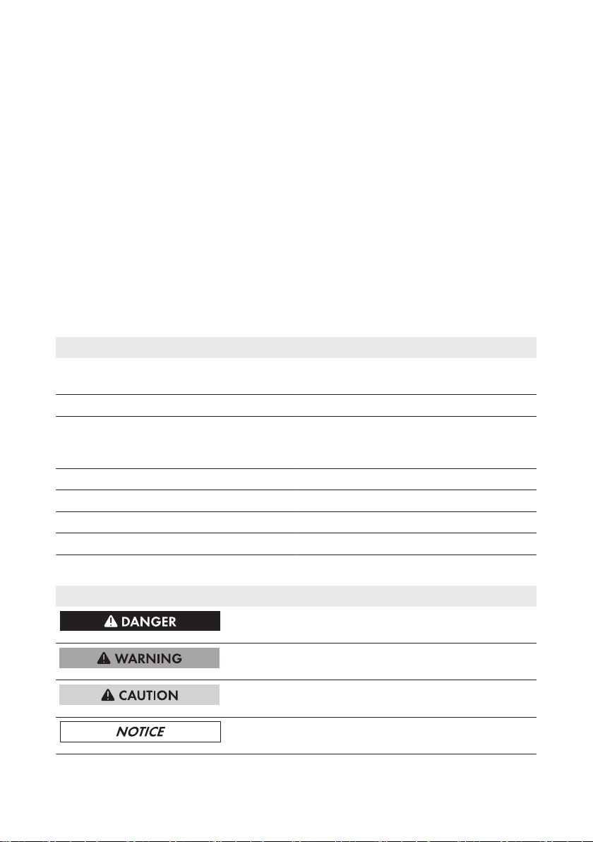
Indicates a hazardous situation which, if not
avoided, will result in death or serious injury
Indicates a hazardous situation which, if not
avoided, can result in death or serious injury
Indicates a hazardous situation which, if not
avoided, can result in minor or moderate injury
Indicates a situation which, if not avoided, can result in property damage
Service ManualSB36-50SE-SG-en-104
Page 5
SMA Solar Technology AG
1 Information on this Document
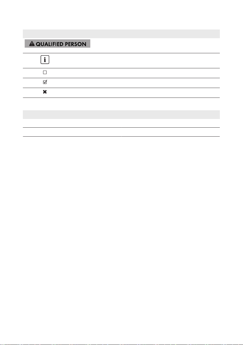
Symbol Explanation
Sections describing activities to be performed by
qualified persons only
Information that is important for a specific topic or
goal, but is not safety-relevant
Indicates a requirement for meeting a specific goal
Desired result
A problem that might occur
Nomenclature
Complete designation Designation in this document
Battery Pack Smart Energy BatteryPack
Sunny Boy 3600 / 5000 Smart Energy Inverter, product
Service Manual 5SB36-50SE-SG-en-10
Page 6

2 Safety
SMA Solar Technology AG
2 Safety
2.1 Skills of Qualified Persons
The tasks described in this document must only be performed by qualified persons. Qualified
persons must have the following skills:
• Knowledge of how an inverter works and is operated
• Training in how to deal with the dangers and risks associated with installing and using
electrical devices, batteries and systems
• Training in the installation and commissioning of electrical devices and systems
• Knowledge of the applicable standards and directives
• Knowledge of and compliance with this document and all safety precautions
• Knowledge of and compliance with the documents of the battery manufacturer and all safety
precautions
• Knowledge of and compliance with the regulations of the European Agreement concerning
the International Carriage of Dangerous Goods by Road (ADR) for packaging, transport and
labeling of dangerous goods
• Training in accordance with Section 1.3 ADR for packaging and transport of the Battery Pack
Smart Energy
2.2 Safety Precautions
This section contains safety precautions that must be observed at all times when working on or with
the product.
To prevent personal injury and property damage and to ensure long-term operation of the product,
read this section carefully and follow all safety precautions at all times.
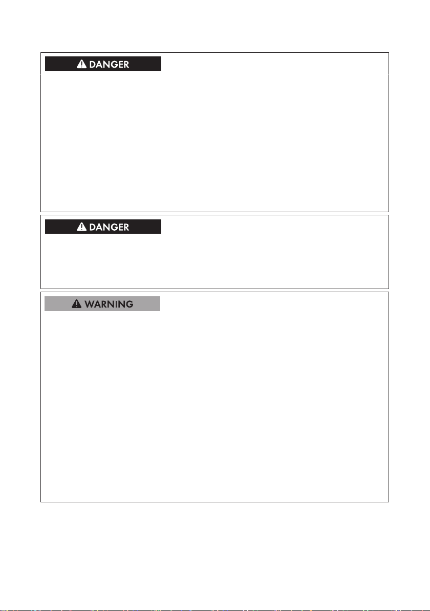
Danger to life due to high voltages of the PV array
When exposed to sunlight, the PV array generates dangerous DC voltage which is present in the
DC conductors and the live components of the inverter. Touching the DC conductors or the live
components can lead to lethal electric shocks. If you disconnect the DC connectors from the
inverter under load, an electric arc may occur leading to electric shock and burns.
• Do not touch uninsulated cable ends.
• Do not touch the DC conductors.
• Do not touch any live components of the inverter.
• Have the inverter mounted, installed and commissioned by qualified persons with the
appropriate skills only.
• If an error occurs, have it rectified by qualified persons only.
• Prior to performing any work on the inverter, disconnect it from all voltage sources as
described in this document (see Section2.3, page8).
Service ManualSB36-50SE-SG-en-106
Page 7
SMA Solar Technology AG
Danger to life due to high voltages on the BatteryPack
Lethal voltage is present at the pin connector for the power cable. Reaching into the pin
connector for the power cable can result in lethal electric shock.
• Do not open the BatteryPack.
• Do not wipe over the Battery Pack with a damp cloth.
• Leave the protective caps on the pin connectors for the power cable and the data cable until
the inverter cables are connected to the Battery Pack.
• Only operate the BatteryPack with its protective cover. The protective cover is separately
packed.
• Prior to performing any work on the inverter or the Battery Pack, disconnect the inverter from
all voltage sources as described in this document (see Section2.3, page8).
Danger to life due to electric shock
Touching an ungrounded PV module or an array frame can cause a fatal electric shock.
• Connect and ground the PV modules, array frame and electrically conductive surfaces so
that there is continuous conduction. Observe the applicable local regulations.
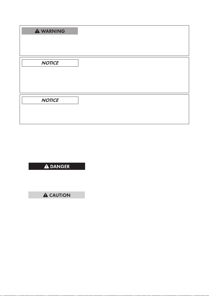
Risk of chemical burns from electrolyte or toxic gases
During normal operation, no electrolyte can leak from the Battery Pack and no toxic gases can
form. Despite careful construction, if the Battery Pack is damaged or a fault occurs, it is possible
that electrolyte may be leaked or toxic gases formed.
• Store the Battery Pack in a cool and dry place.
• Do not drop the Battery Pack or damage it with sharp objects.
• Only set the Battery Pack down on its back, i.e., on the side with the mounting lugs.
• Do not open the BatteryPack.
• Only operate the Battery Pack at ambient temperatures between 0°C and +40°C.
• Do not install or operate the Battery Pack in potentially explosive atmospheres or areas of
high humidity.
• If moisture has penetrated the Battery Pack (e.g. due to a damaged enclosure), do not install
or operate the Battery Pack.
• In case of contact with electrolyte, rinse the affected areas immediately with water and
consult a doctor without delay.
2 Safety
Service Manual 7SB36-50SE-SG-en-10
Page 8
2 Safety
Risk of burns due to hot enclosure parts
Some parts of the enclosure can get hot during operation.
• During operation, do not touch any parts other than the enclosure lid of the inverter.
Damage to the inverter due to electrostatic discharge
Touching electronic components can cause damage to or destroy the inverter through
electrostatic discharge.
• Ground yourself before touching any component.
Damage to the display or the type label due to the use of cleaning agents
• If the inverter is dirty, clean the enclosure, the cooling fins, the enclosure lid, the type label,
the display and the LEDs using only water and a cloth.
SMA Solar Technology AG
2.3 Disconnecting the Inverter from Voltage Sources
1. Disconnect the circuit breaker and secure it against reconnection.
2. If the multi-function relay is used, switch off the load supply voltage, if necessary.
3. Turn the DC load-break switch towards OFF until it snaps into place at position O.
4. Wait until all LEDs and the display have gone out.
5.
Danger to life due to high voltages
The capacitors in the inverter take five minutes to discharge.
• Wait five minutes before opening the enclosure lid.
6.
Risk of injury from dropping the enclosure lid
After removing the last screw, the enclosure lid could fall off.
• Remove all screws of the enclosure lid using an Allen key (AF5). When removing the last
screw, support the enclosure lid with one hand. Then remove the enclosure lid by pulling
it forwards and make sure that the conical spring washers are retained.
Service ManualSB36-50SE-SG-en-108
Page 9
SMA Solar Technology AG
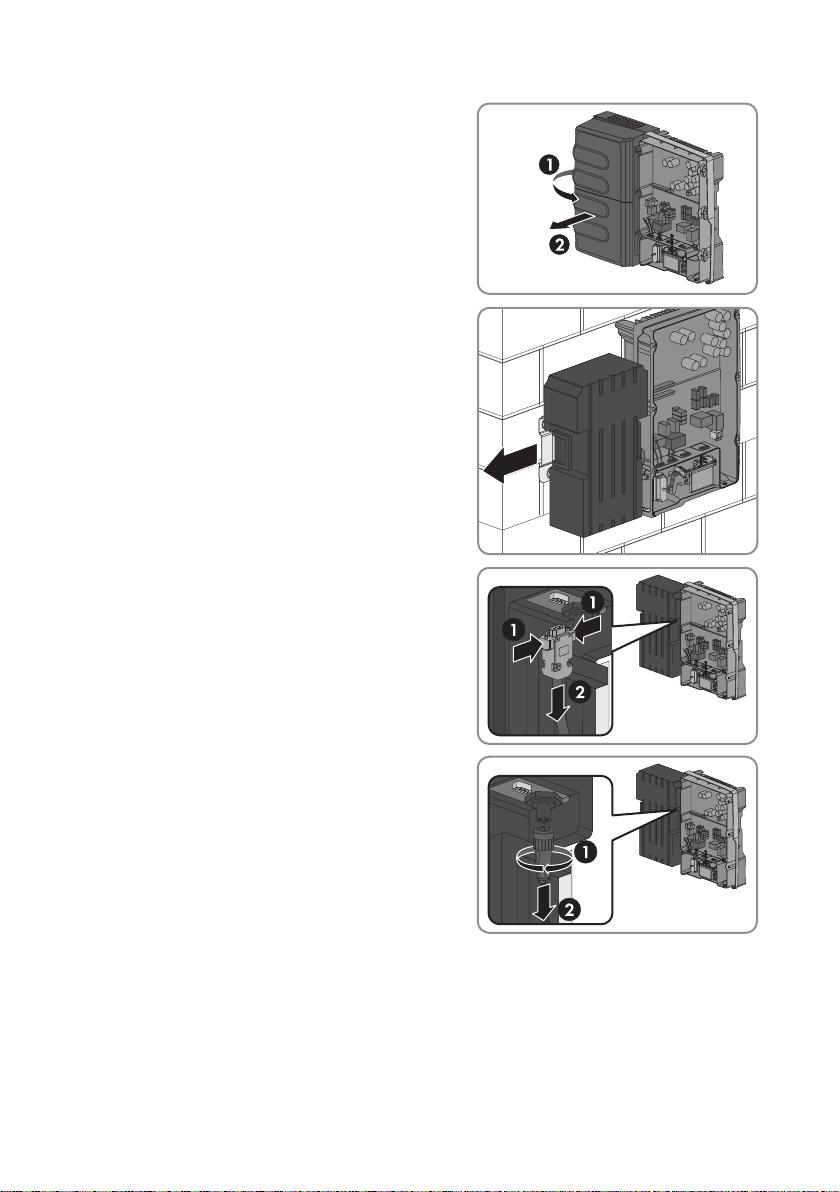
7. Grip behind the left-hand side of the protective
cover and lever it loose. Then lift the protective
cover forwards and off.
8. Hold the Battery Pack by the side handles, and
slide it to the left of the wall mounting plate up to
the stop. This deactivates the lift-off protection of
the Battery Pack and gives you more room to
pull out the cables.
9. Remove the data cable from the BatteryPack.
Press the lateral brackets in and pull the plug out
of the pin connector.
2 Safety
10. Remove the power cable from the BatteryPack.
Turn the mating plug to the left until it releases
and pull it out of the pin connector.
11. If the protective caps of the pin connectors for the data cable and the power cable are
available, use them to cover the corresponding pin connectors of the Battery Pack.
12. Insert the data cable and power cable into the bracket on the left-hand side of the inverter.
Service Manual 9SB36-50SE-SG-en-10
Page 10
2 Safety
SMA Solar Technology AG
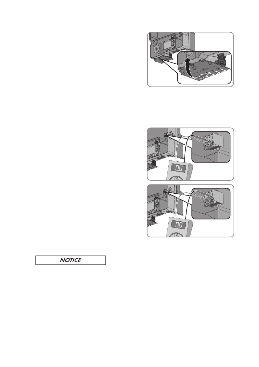
13. Flip the DC contact protection up and press
firmly until it snaps into place.
14. Use a current clamp to ensure that no current is present in the DC cables.
15. Unlock and remove all DC connectors. Insert a flat-blade screwdriver or an angled
screwdriver (blade width: 3.5mm) into one of the side slots and pull the DC connectors
straight out. Do not pull on the cable.
16. Ensure that no voltage is present at the DC inputs on the inverter.
17. Ensure that no voltage is present on the
ACconnecting terminal plate between L and N
using a suitable measuring device. Insert a test
probe in each round opening of the terminal.
18. Ensure that no voltage is present on the
ACconnecting terminal plate between L and PE
using a suitable measuring device. Insert a test
probe in each round opening of the terminal.
19. If you are using the multifunction relay, ensure that no voltage is present between any of the
terminals on the multifunction relay and PE on the AC connecting terminal plate.
20.
Damage to the inverter due to electrostatic discharge
Touching electronic components can cause damage to or destroy the inverter through
electrostatic discharge.
• Ground yourself before touching any component.
Service ManualSB36-50SE-SG-en-1010
Page 11
SMA Solar Technology AG
3 Cleaning the Inverter
3 Cleaning the Inverter
Damage to the display or the type label due to the use of cleaning agents
• If the inverter is dirty, clean the enclosure, the cooling fins, the enclosure lid, the type label,
the display and the LEDs using only water and a cloth.
• If the cooling fins on the rear of the enclosure are dirty, clean them using a soft brush.
• If the air ducts on the top of the inverter are dirty, clean them using a soft brush.
• If the protective cover of the Battery Pack is dirty, clean it with a dry cloth.
• If the Battery Pack is dirty, clean it with a dry cloth.
Service Manual 11SB36-50SE-SG-en-10
Page 12
4 Troubleshooting
SMA Solar Technology AG
4 Troubleshooting
4.1 LED Signals
The LEDs indicate the operating state of the inverter.
LED Status Explanation
Green LED glowing Operation
flashing The requirements for the connection to the utility
grid have not been met.
Red LED glowing Error
The red LED indicates an error (see Section4.3
"Error Messages", page13).
Blue LED - No function
4.2 Event Messages
Display message Cause
Set parameter The parameter change is adopted.
Parameters set success-
fully
Update file OK The update file found is valid.
Memory card is read USB stick (memory card) is searched for the update file and the update
No new update on the
memory card
Update communication The inverter is updating the communication component.
Update main CPU The inverter is updating the inverter component.
Update completed The inverter has successfully completed the update.
Condition test success-
ful
Update transport
started
Update transport suc-
cessful
Update BMS Battery management software (BMS) is updated.
Grid parameter un-
changed
The parameter changes were successfully adopted.
file is checked.
On the USB stick (memory card), there is an update file that has already
been used.
Conditions from the update file have been tested successfully.
Update file is being copied.
Update file was copied successfully to the inverter's internal memory.
The parameters have been locked and cannot be changed.
Service ManualSB36-50SE-SG-en-1012
Page 13

SMA Solar Technology AG
4.3 Error Messages
Error number Display message, cause and corrective measures
101 to 103
202 to 205
Grid fault
The grid voltage or grid impedance at the connection point of the inverter
is too high. The inverter has disconnected from the utility grid.
Corrective measures:
• Check whether the grid voltage at the connection point of the
inverter is permanently in the permissible range. If the grid voltage is
outside the permissible range due to local grid conditions, contact
the grid operator. The grid operator must agree with an adjustment
of the voltage at the feed-in point or with a change of the monitored
operating limits.
If the grid voltage is permanently within the permissible range and
this message is still displayed, contact the SMAServiceLine.
Grid fault
The utility grid has been disconnected, the AC cable is damaged or the
grid voltage at the connection point of the inverter is too low. The inverter
has disconnected from the utility grid.
Corrective measures:
• Make sure that the circuit breaker is switched on.
• Make sure that the AC cable is not damaged.
• Make sure that the AC cable is correctly connected.
• Check whether the grid voltage at the connection point of the
inverter is permanently in the permissible range.
If the grid voltage is outside the permissible range due to local grid
conditions, contact the grid operator. The grid operator must agree
with an adjustment of the voltage at the feed-in point or with a
change of the monitored operating limits.
If the grid voltage is permanently within the permissible range and
this message is still displayed, contact the SMAServiceLine.
4 Troubleshooting
Service Manual 13SB36-50SE-SG-en-10
Page 14

4 Troubleshooting
SMA Solar Technology AG
Error number Display message, cause and corrective measures
301
Grid fault
The ten-minute average value of the grid voltage is no longer within the
permissible range. The grid voltage or grid impedance at the connection
point is too high. The inverter disconnects from the utility grid to comply
with the power quality.
Corrective measures:
• Check whether the grid voltage at the connection point of the
inverter is permanently in the permissible range.
If the grid voltage is outside the permissible range due to local grid
conditions, contact the grid operator. The grid operator must agree
with an adjustment of the voltage at the feed-in point or with a
change of the monitored operating limits.
If the grid voltage is permanently within the permissible range and
this message is still displayed, contact the SMAServiceLine.
401 to 404
Grid fault
The inverter is no longer in grid-parallel operation. The inverter has
stopped feeding into the utility grid.
Corrective measures:
• Check the grid connection for significant, short-term frequency
fluctuations.
501
Grid fault
The power frequency is not within the permissible range. The inverter has
disconnected from the utility grid.
Corrective measures:
• If possible, check the power frequency and observe how often
fluctuations occur.
If fluctuations occur frequently and this message is displayed often,
contact the grid operator and request approval to change the
operating parameters of the inverter.
If the grid operator gives his approval, discuss any changes to the
operating parameters with the SMAServiceLine.
601
Grid fault
The inverter has detected an excessively high proportion of direct current
in the grid current.
Corrective measures:
• Check the grid connection for direct current.
• If this message is displayed frequently, contact the grid operator and
check whether the monitoring threshold on the inverter can be
raised.
Service ManualSB36-50SE-SG-en-1014
Page 15

SMA Solar Technology AG
Error number Display message, cause and corrective measures
701
Frequency not permitted > Check parameter
The power frequency is not within the permissible range. The inverter has
disconnected from the utility grid.
Corrective measures:
• If possible, check the power frequency and observe how often
fluctuations occur.
If fluctuations occur frequently and this message is displayed often,
contact the grid operator and request approval to change the
operating parameters of the inverter.
If the grid operator gives his approval, discuss any changes to the
operating parameters with the SMAServiceLine.
801
Waiting for grid voltage > Grid failure > Check fuse
The AC cable is not correctly connected or the country data set is not correctly configured.
Corrective measures:
• Ensure that the AC cable is correctly connected (see inverter manual
at www.SMA-Solar.com).
• Ensure that the country data set has been configured correctly.
Check the setting of the rotary switches A and B or select the
operating parameter Set country standard and check the value.
• Check the fuse.
901
PE conn. missing > Check connection
The grounding conductor is not correctly connected.
Corrective measures:
• Ensure that the grounding conductor is correctly connected (see
inverter manual at www.SMA-Solar.com).
1001
L / N swapped > Check connection
The connection of L and N is swapped.
Corrective measures:
• Ensure that L and N are correctly connected (see inverter manual at
www.SMA-Solar.com).
1101
Installation fault > Check connection
A second line conductor is connected to N.
Corrective measures:
• Correct the AC connection (see inverter manual at www.SMASolar.com).
4 Troubleshooting
Service Manual 15SB36-50SE-SG-en-10
Page 16

4 Troubleshooting
SMA Solar Technology AG
Error number Display message, cause and corrective measures
1501
Reconnection fault grid
The changed country data set or the value of a parameter you have set
does not correspond to the local requirements. The inverter cannot connect to the utility grid.
Corrective measures:
• Ensure that the country data set has been configured correctly.
Check the setting of the rotary switches A and B or select the
operating parameter Set country standard and check the value.
3301 to 3303
Unstable operation
The ten-minute average value of the grid voltage is no longer within the
permissible range. The grid voltage or grid impedance at the connection
point is too high. The inverter disconnects from the utility grid to comply
with the power quality.
Corrective measures:
• Check whether the grid voltage at the connection point of the
inverter is permanently in the permissible range.
If the grid voltage is outside the permissible range due to local grid
conditions, contact the grid operator. The grid operator must agree
with an adjustment of the voltage at the feed-in point or with a
change of the monitored operating limits.
If the grid voltage is permanently within the permissible range and
this message is still displayed, contact the SMAServiceLine.
3401 to 3402
DC overvoltage > Disconnect generator
Overvoltage at DC input. This can destroy the inverter.
This message is additionally highlighted by rapid flashing of the back-
light.
Corrective measures:
• Immediately disconnect the inverter from all voltage sources (see
Section2.3, page8).
• Check whether the DC voltage is below the maximum input voltage
of the inverter. If the DC voltage is below the maximum input voltage
of the inverter, reconnect the DC connectors to the inverter.
• If the DC voltage is above the maximum input voltage of the
inverter, ensure that the PV array has been correctly rated or contact
the installer of the PV array.
• If this message is displayed frequently, contact the
SMAServiceLine.
Service ManualSB36-50SE-SG-en-1016
Page 17

SMA Solar Technology AG
Error number Display message, cause and corrective measures
3405
IRE defective > Disconnect the PV array
Corrective measures:
• Immediately disconnect the inverter from all voltage sources (see
Section2.3, page8).
• Check whether the DC voltage is below the maximum input voltage
of the inverter. If the DC voltage is below the maximum input voltage
of the inverter, reconnect the DC connectors to the inverter.
• If the DC voltage is above the maximum input voltage of the
inverter, ensure that the PV array has been correctly rated or contact
the installer of the PV array.
• If this message is displayed frequently, contact the
SMAServiceLine.
3501
Insulation failure > Check generator
The inverter has detected a ground fault in the PV array.
Corrective measures:
• Check the PV system for ground faults (see Section5, page26).
3601
High discharge current > Check generator
The leakage current from the inverter and the PV array is too high. There
is a ground fault, a residual current or a malfunction.
The inverter interrupts feed-in operation immediately after exceeding a
limiting value. When the fault is eliminated, the inverter automatically reconnects to the utility grid.
Corrective measures:
• Check the PV system for ground faults (see Section5, page26).
3701
Residual current too high > Check generator
The inverter has detected a residual current due to temporary grounding
of the PV array.
Corrective measures:
• Check the PV system for ground faults (see Section5, page26).
3801 to 3802
DC overcurrent > Check generator
Overcurrent at the DC input. The inverter briefly interrupts feed-in operation.
Corrective measures:
• If this message is displayed frequently, ensure that the PV array has
been correctly rated and wired.
4 Troubleshooting
Service Manual 17SB36-50SE-SG-en-10
Page 18

4 Troubleshooting
SMA Solar Technology AG
Error number Display message, cause and corrective measures
3901 to 3902
Waiting for DC start conditions > Start conditions not met
The feed-in conditions for the utility grid are not yet fulfilled.
Corrective measures:
• Wait for higher irradiation.
• If this message is displayed frequently in the morning, increase the
voltage limit for starting grid feed-in. Change the parameter Critical
voltage to start feed-in.
• If this message is displayed frequently with medium irradiation,
ensure that the PV array is correctly rated.
6001 to 6462
Self diagnosis > Interference of device
The cause must be determined by the SMAServiceLine.
Corrective measures:
• Contact the SMAServiceLine.
6501 to 6513
Self diagnosis > Overtemperature
The inverter has switched off due to excessive temperature.
Corrective measures:
• Clean the cooling fins on the rear of the enclosure and the air ducts
on the top using a soft brush.
• Ensure that the inverter has sufficient ventilation.
6603 to 6604
Self diagnosis > Overload
The inverter has detected an internal overload and interrupts the feed-in
operation.
Corrective measures:
• Contact the SMAServiceLine.
6607 to 6608
Self-diagnosis > Battery overcurrent
Internal error. The inverter continues to feed into the utility grid.
Corrective measures:
• If this message is displayed frequently, contact the
SMAServiceLine.
6609
Self-diagnosis > Battery undervoltage
Internal error. The inverter continues to feed into the utility grid.
Corrective measures:
• If this message is displayed frequently, contact the
SMAServiceLine.
Service ManualSB36-50SE-SG-en-1018
Page 19

SMA Solar Technology AG
Error number Display message, cause and corrective measures
6610
Self-diagnosis > Battery overvoltage
Corrective measures:
• Turn the DC load-break switch towards OFF until it snaps into place
at position O.
• Contact the SMA Service Line and clarify the next steps.
6701 to 6702
Comm. disturbed
An error has occurred in the internal communication of the inverter. The
inverter continues feeding power into the grid.
Corrective measures:
• If this message is displayed frequently, contact the
SMAServiceLine.
6801 to 6802
Self diagnosis > Input A defective
Input A of the inverter is defective.
Corrective measures:
• Contact the SMAServiceLine.
6901 to 6902
Self diagnosis > Input B defective
Input B of the inverter is defective.
Corrective measures:
• Contact the SMAServiceLine.
7001 to 7002
Sensor fault
A temperature sensor in the inverter is defective and the inverter interrupts
the feed-in operation.
Corrective measures:
• Contact the SMAServiceLine.
7008
Disturbance sensor display temperature
The ambient temperature sensor is defective. The display is not switched
off at temperatures below -25°C and, as a result, it may have been destroyed. The inverter continues feeding power into the grid.
Corrective measures:
• Contact the SMAServiceLine.
7102
Parameter file not found or defective
The parameter file was not found or is defective. The update failed. The
inverter continues feeding power into the grid.
Corrective measures:
• Copy the parameter file to the correct folder again.
4 Troubleshooting
Service Manual 19SB36-50SE-SG-en-10
Page 20

4 Troubleshooting
SMA Solar Technology AG
Error number Display message, cause and corrective measures
7105
Param. setting failed
Parameters could not be set using the memory card. The inverter continues to feed in.
Corrective measures:
• Ensure that the parameters are set correctly.
• Ensure that you have an SMA Grid Guard code.
7106
Update file defect.
Update file on the memory card is defective.
Corrective measures:
• Reformat the memory card.
• Re-save the files to the memory card.
7110
No update file
No update file has been found.
Corrective measures:
• Copy the update file to the memory card folder. Select the folder
\UPDATE.
7112
Update file copied
The update file was successfully copied to the memory of the inverter processor.
7201 to 7202
Data stor. not poss.
Internal error. The inverter continues to feed into the utility grid.
Corrective measures:
• Contact the SMAServiceLine.
7303
Update main CPU failed
The cause must be determined by the SMAServiceLine.
Corrective measures:
• Contact the SMAServiceLine.
7324
Wait for update conditions
The inverter has successfully completed the update.
7330
Condition test failed
The conditions of the update file used for the inverter settings (e.g. country data set, device type) are not fulfilled.
Corrective measures:
• Contact the SMAServiceLine.
Service ManualSB36-50SE-SG-en-1020
Page 21

SMA Solar Technology AG
Error number Display message, cause and corrective measures
7333
Update transport failed
The update was not carried out successfully.
Corrective measures:
• Restart the update.
7337
Update BMS failed
The cause must be determined by the SMAServiceLine.
Corrective measures:
• Contact the SMAServiceLine.
7340
Update communication failed
The cause must be determined by the SMAServiceLine.
Corrective measures:
• Contact the SMAServiceLine.
7401
Varistor defective
At least one of the thermally monitored varistors is defective.
Corrective measures:
• Check the function of the varistors (see Section6, page29).
7701 to 7703
Self diagnosis > Interference of device
The cause must be determined by the SMAServiceLine.
Corrective measures:
• Contact the SMAServiceLine.
8001
Derating occurred
The inverter has reduced its power output for more than ten minutes due
to excessive temperature.
Corrective measures:
• Clean the cooling fins on the rear of the enclosure and the air ducts
on the top using a soft brush.
• Ensure that the inverter has sufficient ventilation.
8902
Self-diagnosis > Battery controller relay defective
The cause must be determined by the SMAServiceLine.
Corrective measures:
• Contact the SMAServiceLine.
8903
Battery controller defective > Disconnect PV array, open DC
switch
The cause must be determined by the SMAServiceLine.
Corrective measures:
• Contact the SMAServiceLine.
4 Troubleshooting
Service Manual 21SB36-50SE-SG-en-10
Page 22

4 Troubleshooting
SMA Solar Technology AG
Error number Display message, cause and corrective measures
8904
Self diagnosis > Interference of device
The cause must be determined by the SMAServiceLine.
Corrective measures:
• Contact the SMAServiceLine.
9002
Grid Guard code invalid
The SMA Grid Guard code entered is incorrect. The operating parameters are still protected and cannot be changed.
Corrective measures:
• Enter the correct SMA Grid Guard code.
9003
Grid parameter locked
The parameters are now locked. You cannot change the parameters.
Corrective measures:
• Unlock the parameters with the SMA Grid Guard code.
9005
Changing grid params not possible > Ensure DC supply
PV power is too low for setting the country data set. As soon as sufficient
irradiation is available, the inverter assumes the setting automatically.
9007
Abort self-test
The self-test (Italy only) was terminated.
Corrective measures:
• Restart the self-test (see inverter manual at www.SMA-Solar.com).
9301
New battery detected
The inverter has detected a new Battery Pack.
9302
Self diagnosis > Interference of device
The cause must be determined by the SMAServiceLine.
Corrective measures:
• Contact the SMAServiceLine.
9303
The service life of the battery is expiring
The state of health of the Battery Pack is 70%.
Corrective measures:
• Replace the Battery Pack with a new one. Contact the SMA Service
Line.
Service ManualSB36-50SE-SG-en-1022
Page 23

SMA Solar Technology AG
Error number Display message, cause and corrective measures
9304
Fault in battery connection > Check battery connection
The connection between the Battery Pack and the inverter is disrupted.
Corrective measures:
• Ensure that the power cable and the data cable are properly
connected to the Battery Pack (see inverter manual at www.SMASolar.com).
• Ensure that the plug contacts of the power cable and the data cable
are not damaged.
9305
Unauthorized battery system
The Battery Pack is not suitable for operation with the inverter.
Corrective measures:
• If the battery has been approved by SMA for operation with the
inverter, contact the SMA Service Line.
9306
Deviation in battery voltage
The cause must be determined by the SMAServiceLine.
Corrective measures:
• Contact the SMAServiceLine.
9307
Battery system defective
The cause must be determined by the SMAServiceLine.
Corrective measures:
• Contact the SMAServiceLine.
9308
Communication fault in battery system > Check battery connection
The connection between the Battery Pack and the inverter is disrupted.
Corrective measures:
• Ensure that the power cable and the data cable are properly
connected to the Battery Pack (see inverter manual at www.SMASolar.com).
• Ensure that the plug contacts of the power cable and the data cable
are not damaged.
9309
Battery system defective
The Battery Pack is defective.
Corrective measures:
• Contact the SMAServiceLine.
4 Troubleshooting
Service Manual 23SB36-50SE-SG-en-10
Page 24

4 Troubleshooting
SMA Solar Technology AG
Error number Display message, cause and corrective measures
9310
Signal fault in battery system > Check battery connection
The connection between the Battery Pack and the inverter is disrupted.
Corrective measures:
• Ensure that the power cable and the data cable are properly
connected to the Battery Pack (see inverter manual at www.SMASolar.com).
• Ensure that the plug contacts of the power cable and the data cable
are not damaged.
9311
Battery cell overvoltage fault
The voltage of at least one cell is outside the threshold.
Corrective measures:
• Immediately disconnect the inverter from all voltage sources (see
Section2.3, page8).
• Contact the SMAServiceLine.
9312
Battery cell undervoltage fault
The cause must be determined by the SMAServiceLine.
Corrective measures:
• Contact the SMAServiceLine.
9313
Low temperature fault in battery > Check installation site
The ambient temperature is below the lowest permitted temperature. The
inverter and the Battery Pack must only be operated at ambient temperatures from 0°C to 40°C.
Corrective measures:
• Ensure that the permitted ambient temperatures are complied with at
the installation site.
• If this message is displayed even though the permitted ambient
temperature is complied with, contact the SMA Service Line.
9314
Overtemperature fault in battery > Check installation site
The ambient temperature is above the highest permitted temperature. The
inverter and the Battery Pack must only be operated at ambient temperatures from 0°C to 40°C.
Corrective measures:
• Ensure that the permitted ambient temperatures are complied with at
the installation site.
• If this message is displayed even though the permitted ambient
temperature is complied with, contact the SMA Service Line.
Service ManualSB36-50SE-SG-en-1024
Page 25

SMA Solar Technology AG
Error number Display message, cause and corrective measures
9315
Battery imbalancing fault
The cause must be determined by the SMAServiceLine.
Corrective measures:
• Contact the SMAServiceLine.
9334
Battery charging test
The function of the Battery Pack is tested. The Battery Pack is charged.
9335
Discharge battery test
The function of the Battery Pack is tested. The Battery Pack is discharged.
9336
Start conditions for battery test not fulfilled
The function of the Battery Pack cannot be tested because the requirements are not fulfilled.
Corrective measures:
• Ensure that the requirements for testing the Battery Pack are
fulfilledTesting the Function of the Battery Pack.
9337
Charge battery test successful
The Battery Pack was charged successfully. The function of the Battery
Pack is ensured.
9338
Battery discharging test successful
The Battery Pack was discharged successfully. The function of the Battery
Pack is ensured.
9339
Battery charging test failed
The Battery Pack could not be charged.
Corrective measures:
• Ensure that the function of the Battery Pack was tested correctly
Testing the Function of the Battery Pack.
9340
Battery discharging test failed
The Battery Pack could not be discharged.
Corrective measures:
• Ensure that the function of the Battery Pack was tested correctly
Testing the Function of the Battery Pack.
4 Troubleshooting
Service Manual 25SB36-50SE-SG-en-10
Page 26

5 Checking the PV System for Ground Faults
SMA Solar Technology AG
5 Checking the PV System for Ground Faults
If the inverter displays the event numbers 3501, 3601 or 3701, there could be a ground fault. The
electrical insulation from the PV system to ground is defective or insufficient.
Danger to life due to electric shock
In the event of a ground fault, high voltages can be present.
• Touch the cables of the PV array on the insulation only.
• Do not touch any parts of the sub-structure or frame of the PV array.
• Do not connect PV strings with ground faults to the inverter.
Destruction of the measuring device due to overvoltage
• Only use measuring devices with a DC input voltage range of 1,000V or higher.
Procedure
• Check the PV system for ground faults by measuring the voltage.
• If the voltage measurement was not successful, check the PV system via insulation resistance
measurement for ground faults.
Test by Measuring the Voltage
Proceed as follows to check each string in the PV system for ground faults.
Procedure:
1.
Danger to life due to high voltages
• Disconnect the inverter from all voltage sources (see Section2.3, page8).
2. Measure the voltages:
• Measure the voltages between the positive terminal and the ground potential (PE).
• Measure the voltages between the negative terminal and the ground potential (PE).
• Measure the voltages between the positive and negative terminals.
If the following results are present at the same time, there is a ground fault in the PV
system:
☑ All measured voltages are stable.
☑ The sum of the two voltages to ground potential is approximately equal to the
voltage between the positive and negative terminals.
• If a ground fault is present, determine the location of the ground fault via the ratio of the
two measured voltages and eliminate the ground fault.
Service ManualSB36-50SE-SG-en-1026
Page 27

SMA Solar Technology AG
5 Checking the PV System for Ground Faults
Example: Location of the ground fault
The example shows a ground fault between the second and third PV module.
3. If a definite ground fault cannot be measured and the message is still displayed, measure the
insulation resistance.
4. Reconnect the strings without ground fault to the inverter and recommission the inverter (see
Section9, page33).
Test by Measuring the Insulation Resistance
If the voltage measurement does not accurately indicate a ground fault, the insulation resistance
measurement can provide more detailed results.
Figure 1: Schematic diagram of the measurement
Service Manual 27SB36-50SE-SG-en-10
Page 28

total
5 Checking the PV System for Ground Faults
SMA Solar Technology AG
Calculating the insulation resistance
The total resistance of the PV system to be expected or of an individual string can be
calculated using the following formula:
The exact insulation resistance of a PV module can be obtained from the module manufacturer
or the datasheet.
For the resistance of a PV module an average value can be assumed: for thin-film PV modules
approximately 40MOhm and for polycrystalline and monocrystalline PV modules
approximately50MOhm per PV module (for further information on calculating the insulation
resistance see the Technical Information "Insulation Resistance (Riso) of Non-Galvanically
Isolated PV Systems" at www.SMA-Solar.com).
Required devices:
☐ Suitable device for safe disconnection and short-circuiting
☐ Measuring device for insulation resistance
Device required for safe disconnection and short-circuiting of the PV array
The insulation resistance can only be measured with a suitable device for safe disconnection
and short-circuiting of the PV array. If no suitable device is available, the insulation
measurement must not be carried out.
Procedure:
1. Calculate the insulation resistance per string to be expected.
2.
Danger to life due to high voltages
• Disconnect the inverter from all voltage sources (see Section2.3, page8).
3. Install the short circuit device.
4. Connect the measuring device for insulation resistance.
5. Short-circuit the first string.
6. Set the test voltage. The test voltage should be as close as possible to the maximum system
voltage of the PV modules but must not exceed it (see datasheet of the PV modules).
7. Measure the insulation resistance.
8. Eliminate the short circuit.
9. Measure the remaining strings in the same manner.
☑ If the insulation resistance of a string deviates considerably from the theoretically
calculated value, there is a ground fault present in the respective string.
10. Reconnect only those strings to the inverter from which the ground fault was eliminated.
11. Reconnect all other strings to the inverter.
12. Recommission the inverter (see Section9, page33).
13. If the inverter still displays an insulation error, contact the SMAServiceLine. The PV modules
might not be suitable for the inverter in the present quantity.
Service ManualSB36-50SE-SG-en-1028
Page 29

SMA Solar Technology AG
6 Checking the Function of the Varistors
6 Checking the Function of the Varistors
If the inverter displays event number 7401, one of the varistors is probably defective.
Destruction of the inverter due to overvoltage
If varistors are missing, the inverter is no longer protected against overvoltage.
• Do not operate the inverter without varistors in PV systems with a high risk of overvoltages.
• Do not recommission the inverter until the defective varistors have been replaced.
Destruction of the measuring device due to overvoltage
• Only use measuring devices with a DC input voltage range of 1,000V or higher.
Check the function of each varistor as described in the following:
Procedure:
1.
Danger to life due to high voltages
• Disconnect the inverter from all voltage sources and open the enclosure lid (see
Section2.3, page8).
2. Insert the insertion tool in the clamping contacts
of the connecting terminal plate.
3. Remove the varistor from the connecting terminal plate.
4. Use a measuring device to measure whether
there is a conductive connection between the
middle and the right-hand varistor lead. Hold the
varistor with the labeling pointing forward.
If there is no conductive connection, the varistor is defective. SMA Solar Technology AG
recommends replacing all varistors immediately.
• Order new varistors and insertion tools (see Section11 "Spare Parts", page38).
Service Manual 29SB36-50SE-SG-en-10
Page 30

6 Checking the Function of the Varistors
SMA Solar Technology AG
• Reinsert old varistors and leave them in place until new varistors and insertion tools are
available.
• If new varistors are available, replace all varistors (see Section7, page31).
If a conductive connection is present, contact the SMAServiceLine.
Service ManualSB36-50SE-SG-en-1030
Page 31

SMA Solar Technology AG
7 Replacing the Varistors
Proceed as follows to replace each varistor.
1.
Danger to life due to high voltages
• Disconnect the inverter from all voltage sources and open the enclosure lid (see
Section2.3, page8).
2. Insert the insertion tool in the clamping contacts
of the connecting terminal plate.
3. Remove the varistor from the connecting terminal plate.
4. Insert the new varistor in the connecting terminal
plate. The labeling on the varistor must face
downwards.
7 Replacing the Varistors
5. Remove the insertion tool from the clamping contacts of the connecting terminal plate.
6. Recommission the inverter (see Section9, page33).
Service Manual 31SB36-50SE-SG-en-10
Page 32

8 Testing the Function of the Battery Pack
SMA Solar Technology AG
8 Testing the Function of the Battery Pack
You can test the function of the Battery Pack by manually charging and discharging. The sequence
for charging and discharging depends on the current state of charge of the Battery Pack.
Procedure:
• If the current state of charge of the Battery Pack is lower than 10%, first charge the Battery
Pack until the state of charge has increased to more than 10% and then discharge the Battery
Pack.
• If the current state of charge of the Battery Pack is higher than 95%, first discharge the Battery
Pack until the state of charge has dropped to below 90% and then charge the Battery Pack.
Requirements:
☐ The inverter must be in feed-in operation.
☐ The current PV power must be at least 200W.
☐ The current feed-in AC power must not exceed 90% of the maximum AC power of the inverter.
Charging the Battery Pack
• Select parameter Battery installation mode and set to Charge battery.
☑ The message Charge battery test appears in the display.
☑ The message Battery charging test successful appears in the display. The Battery Pack was
charged successfully.
✖ Does the message Charge battery test failed appear in the display?
The Battery Pack was not charged successfully. The requirements are probably not fulfilled.
• Ensure that the requirements are fulfilled.
• Ensure that the Battery Pack and the inverter are connected correctly.
• Ensure that the Battery Pack is not defective.
• Ensure that the inverter does not display any other error messages.
Discharging the Battery Pack
• Select parameter Battery installation mode and set to Discharge battery.
☑ The message Battery discharging test appears in the display.
☑ The message Battery discharging test successful appears in the display. The Battery Pack
was discharged successfully.
✖ The message Battery discharging test failed appears in the display.
The Battery Pack was not discharged successfully. The requirements are probably not fulfilled.
• Ensure that the requirements are fulfilled.
• Ensure that the Battery Pack and the inverter are connected correctly.
• Ensure that the Battery Pack is not defective.
• Ensure that the inverter does not display any other error messages.
Service ManualSB36-50SE-SG-en-1032
Page 33

SMA Solar Technology AG
9 Recommissioning the Inverter
9 Recommissioning the Inverter
If you have disconnected the inverter from all voltage sources (e.g. for configuration purposes) and
want to recommission it, proceed as follows.
Requirements:
☐ The circuit breaker must be correctly rated.
☐ The inverter and the battery must be correctly mounted.
Procedure:
1. Connect the DC connectors to the inverter.
☑ The DC connectors snap into place.
2. Seal all unused DC inputs using the DC connectors with sealing plugs.
3. Ensure that all DC connectors are securely in place.
4. Flip the DC contact protection down until it
snaps into place.
5. Connect the inverter and the Battery Pack (see inverter manual at www.SMA-Solar.com).
6. Slide the protective cover across the Battery
Pack and push the brackets on the right of the
protective cover into the guides on the left of the
inverter enclosure. Then, press the left side of the
protective cover down onto the Battery Pack until
it snaps into place.
7. Ensure that the DC load-break switch is turned to position OFF. This makes it possible to fit the
enclosure lid to the enclosure.
8. Attach the enclosure lid:
• Attach one conical spring washer to each
screw. The grooved side of the conical
spring washer must point to the screw head.
• Position the enclosure lid on the enclosure using the six screws and tighten all screws
diagonally to each other using an Allen key (AF5) (torque: 6Nm ± 0.5Nm).
Service Manual 33SB36-50SE-SG-en-10
Page 34

9 Recommissioning the Inverter
SMA Solar Technology AG
9. Switch on the circuit breaker.
10. Turn the DC load-break switch towards ON until it snaps into place at position I.
☑ The start-up phase begins.
☑ The green LED is glowing and the display alternates between the firmware version, the serial
number or designation of the inverter, the IP address, the subnet mask, the serial number of the
BatteryPack, the configured country data set and the display language.
✖ The green LED is flashing?
Possible cause of error: the DC input voltage is still too low or the inverter is monitoring the
utility grid.
• Once the DC input voltage is sufficiently high and the grid connection conditions are met,
the inverter will start operation.
✖ The red LED is glowing and an error message and event number appear in the display?
• Eliminate the error (see Section4 "Troubleshooting", page12).
Service ManualSB36-50SE-SG-en-1034
Page 35

SMA Solar Technology AG
10 Decommissioning the Inverter
10 Decommissioning the Inverter
Risk of injury through lifting or dropping the inverter or Battery Pack
The inverter and the Battery Pack are heavy (for weight, see operating manual at www.SMASolar.com). There is risk of injury if the inverter or Battery Pack are lifted incorrectly or dropped
during transport or when attaching or removing it from the wall.
• Hold the inverter by the right-hand and lefthand recessed grips, and lift and transport it to
the mounting position horizontally.
• Lift and transport the Battery Pack by the
lateral handles.
1.
Danger to life due to high voltages
• Disconnect the inverter from all voltage sources (see Section2.3, page8).
2. Remove the AC cable from the inverter. Also push the locking levers right up to the top and
pull out the cables.
3. Press down the locking levers of the connecting terminal plate for the AC cable.
4. If an Ethernet cable is connected for Speedwire communication, remove the cable from the
inverter.
5. If other cables are connected to the inverter, remove the connection cables from the inverter.
Service Manual 35SB36-50SE-SG-en-10
Page 36

10 Decommissioning the Inverter
SMA Solar Technology AG
6. If an additional grounding or equipotential bonding is connected, loosen the cylindrical screw
M6x16 and remove the screw, conical spring washer, clamping bracket and grounding
conductor.
7. Position the enclosure lid on the enclosure using the six screws and tighten all screws
diagonally to each other using an Allen key (AF5) (torque: 6Nm ± 0.5Nm).
8. Remove the battery by lifting it vertically up and
off the wall mounting bracket.
9. Remove the inverter by lifting it vertically up and
off the wall mounting bracket.
10. If the inverter is to be stored or shipped, pack the inverter and the protective cover of the
battery. Use the original packaging or packaging that is suitable for the weight and
dimensions of the inverter and the protective cover.
11. Dispose of the inverter in accordance with the locally applicable disposal regulations for
electronic waste.
12.
Danger to life due to incorrect packaging and transport of the Battery Pack
The Battery Pack is considered to be dangerous goods. If the Battery Pack is to be transported,
special regulations must be complied with for packaging and transport.
• When packaging and transporting the Battery Pack, observe the regulations of the
European Agreement concerning the International Carriage of Dangerous Goods by
Road (ADR).
• Packaging and transport of the Battery Pack may only be carried out by persons who
have been trained in accordance with Section 1.3 ADR and whose training has been
documented.
Service ManualSB36-50SE-SG-en-1036
Page 37

SMA Solar Technology AG
10 Decommissioning the Inverter
13. If the Battery Pack is not damaged and it is to be disposed of, dispose of it in accordance with
the SMA Solar Technology AG regulations.
14. If the Battery Pack is damaged and it is to be disposed of, contact the SMA Service Line and
clarify the procedure for its disposal.
Service Manual 37SB36-50SE-SG-en-10
Page 38

11 Spare Parts
SMA Solar Technology AG
11 Spare Parts
You will find the spare parts for your product in the following overview. If required, these can be
ordered from SMA Solar Technology AG or your distributor.
Designation Brief description SMA order number
Replacement varistors Set with three thermally-moni-
tored varistors incl. insertion
tool
Insertion tool for replacing
varistors
SUNCLIX DC connector Field plug for conductor cross-
Insertion tool for varistors SB-TVWZ
sections of 2.5mm²to6mm²
STP-TV10
SUNCLIX-FC6-SET
Service ManualSB36-50SE-SG-en-1038
Page 39

SMA Solar Technology AG
12 Contact
12 Contact
If you have technical problems concerning our products, contact the SMAServiceLine. We need
the following information in order to provide you with the necessary assistance:
• Inverter device type
• Inverter serial number
• Inverter firmware version
• Type of the BatteryPack
• Serial number of the BatteryPack
• Manufacturing code of the Battery Pack
• Firmware version of the BatteryPack
• Hardware version of the BatteryPack
• Manufacturing week of the Battery Pack
• Special country-specific settings of the inverter (if applicable)
• Type and number of PV modules connected
• Mounting location and mounting altitude of the inverter
• Three-digit or four-digit event number and display message of the inverter
• Optional equipment, e.g. communication products
• Use of the multifunction relay (if present)
Australia SMA Australia Pty Ltd.
Sydney
Belgien/Belgique/België
Brasil Vide España (Espanha)
Česko SMA Central & Eastern Europes.r.o.
Chile Ver España
Danmark Se Deutschland (Tyskland)
SMA Benelux BVBA/SPRL
Mecheln
Praha
Toll free for Australia: 1800SMAAUS
(1800762287)
International: +61294914200
+3215286 730
+420235010417
Service Manual 39SB36-50SE-SG-en-10
Page 40

12 Contact
SMA Solar Technology AG
Deutschland SMA Solar Technology AG
Niestetal
Medium Power Solutions
Wechselrichter: +495619522‑1499
Kommunikation: +495619522‑2499
SMA Online Service Center:
www.SMA.de/Service
Hybrid Energy Solutions
Sunny Island: +495619522-399
PV-Diesel Hybridsysteme:
+495619522-3199
Power Plant Solutions
Sunny Central: +495619522-299
España SMA Ibérica Tecnología Solar,
S.L.U.
Barcelona
France SMA France S.A.S.
Lyon
Llamada gratuita en España:
900142222
Internacional: +34902142424
Medium Power Solutions
Onduleurs : +33472090440
Communication : +33472090441
Hybrid Energy Solutions
Sunny Island : +33472090442
Power Plant Solutions
Sunny Central : +33472090443
India SMA Solar India Pvt. Ltd.
+912261713888
Mumbai
Italia SMA Italia S.r.l.
+39028934-7299
Milano
Κύπρος/Kıbrıs Βλέπε Ελλάδα/ Bkz. Ελλάδα (Yunanistan)
Luxemburg/
Luxembourg
Siehe Belgien
Voir Belgique
Magyarország lásd Česko (Csehország)
Nederland zie Belgien (België)
Österreich Siehe Deutschland
Perú Ver España
Polska Patrz Česko (Czechy)
Portugal SMA Solar Technology Portugal,
Unipessoal Lda
Lisboa
Isento de taxas em Portugal:
800208987
Internacional: +351212377860
Service ManualSB36-50SE-SG-en-1040
Page 41

/01,234
9:;
5%6!78%
9:;*<+%,='3)>+%
SMA Solar Technology AG
România Vezi Česko (Cehia)
Schweiz Siehe Deutschland
Slovensko pozri Česko (Česká republika)
South Africa SMA Solar Technology South Africa
Pty Ltd.
Centurion (Pretoria)
United King-
dom
Ελλάδα SMA Hellas AE
България Вижте Ελλάδα (Гърция)
대한민국 SMA Technology Korea Co., Ltd.서울+822508-8599
SMA Solar UK Ltd.
Milton Keynes
Αθήνα
SMA Solar (Thailand) Co., Ltd. +6626706999
08600SUNNY (0860078669)
International: +27(12)6431785
+441908304899
8012229222
International: +302122229222
12 Contact
中国 SMA Beijing Commercial Company
Ltd.
北京
+9712234-6177 SMA Middle East LLC
Other countries International SMA Service Line
Niestetal
+861056701350
Toll free worldwide: 00800SMASERVICE
(+8007627378423)
Service Manual 41SB36-50SE-SG-en-10
Page 42

SMA Solar Technology
www.SMA-Solar.com
 Loading...