

Page 1
DC Disconnect Switch
For Sunny Boy 3300U/3800U Inverters
Installation Guide Version 1.1 DC-Discon-U-11:SE4406
TBE-DISCONU
Page 2

Page 3

SMA America, Inc.
Copyright © 2004 SMA America, Inc. All rights reserved.
All rights reserved. No part of this document may be reproduced, stored in a retrieval
system, or transmitted, in any form or by any means, electronic, mechanical,
photographic, magnetic or otherwise, without the prior written permission of SMA
America, Inc.
SMA America makes no representations, express or implied, with respect to this
documentation or any of the equipment and/or software it may describe, including
(with no limitation) any implied warranties of utility, merchantability, or fitness for any
particular purpose. All such warranties are expressly disclaimed. Neither SMA America
nor its distributors or dealers shall be liable for any indirect, incidental, or consequential
damages under any circumstances.
(The exclusion of implied warranties may not apply in all cases under some statutes,
and thus the above exclusion may not apply.)
Specifications are subject to change without notice. Every attempt has been made to
make this document complete, accurate and up-to-date. Readers are cautioned,
however, that SMA America reserves the right to make changes without notice and shall
not be responsible for any damages, including indirect, incidental or consequential
damages, caused by reliance on the material presented, including, but not limited to,
omissions, typographical errors, arithmetical errors or listing errors in the content
material.
Installation Guide DC-Discon-U-11:SE4406
Page 4

SMA America, Inc.
DC-Discon-U-11:SE4406 Installation Guide
Page 5

SMA America, Inc.
Introduction . . . . . . . . . . . . . . . . . . . . . . . . . . . . . . . . . . . . . . . . . . . . 3
Unpacking and Inspection . . . . . . . . . . . . . . . . . . . . . . . . . . . . . . . . 5
Wiring . . . . . . . . . . . . . . . . . . . . . . . . . . . . . . . . . . . . . . . . . . . . . . . . 7
Installation . . . . . . . . . . . . . . . . . . . . . . . . . . . . . . . . . . . . . . . . . . . . . 9
Replacing the Fuses . . . . . . . . . . . . . . . . . . . . . . . . . . . . . . . . . . . . .19
Specifications . . . . . . . . . . . . . . . . . . . . . . . . . . . . . . . . . . . . . . . . . .21
Contact . . . . . . . . . . . . . . . . . . . . . . . . . . . . . . . . . . . . . . . . . . . . . . 23
Installation Guide DC-Discon-U-11:SE4406
Page 6

SMA America, Inc.
DC-Discon-U-11:SE4406 Installation Guide
Page 7

SMA America, Inc.
IMPORTANT SAFETY INSTRUCTIONS
*Save These Instructions*
This manual contains important instructions for the DC Disconnect that must be followed
during the installation and use of the DC Disconnect.
The DC Disconnects are designed and tested according to international safety
requirements, but as with all electrical and electronic equipment, certain precautions
must be observed when installing the DC Disconnects. To reduce the risk of personal
injury and to ensure the safe installation and operation of the DC Disconnects, you must
carefully read and follow all instructions and warnings in this Installation Guide.
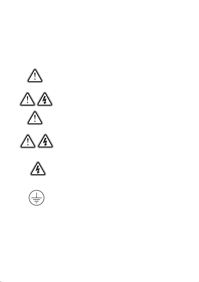
Safety and Hazard Symbols
This symbol is used to call attention to important information that you
must have when installing and/or operating a DC Disconnect. Failure
to read and follow instructions marked with this symbol could result in
serious injury and/or damage to the equipment.
This symbol appears beside instructions and warnings that deal with
dangerous voltages that can injure people who come in contact with
them.
Warnings
WARNING: A Warning describes a hazard to equipment or
personnel. It calls attention to a procedure or practice which, if not
correctly performed or adhered to, could result in damage to or
destruction of part or all of the SMA equipment and/or other
equipment connected to the SMA equipment or personal injury.
Warnings may also be accompanied by one or more of the safety and hazard symbols
described above to indicate the type of hazard described therein.
Other Symbols
In addition to the safety and hazard symbols described previously, the following symbol
is also used in this Installation Guide:
This symbol accompanies notes that call attention to supplementary
information that you should know to ensure optimal operation of the
system.
Installation Guide DC-Discon-U-11:SE4406 1
Page 8
SMA America, Inc.
Warranty
All DC Disconnects sold in the USA have a five-year warranty, as indicated on the
warranty card included in the shipping container. For warranty coverage, or if you
have questions about the DC Disconnect warranty, contact SMA America at the mailing
address, email address, telephone number, or Web site listed in the Contact section of
this manual.
WARNING: All electrical installation must be done in accordance
with the National Electrical Code ANSI/NFPA 70, local building
codes and the requirements of the authority having jurisdiction.
To prevent electrical shock or injury, all wiring and commissioning
procedures must be performed only by qualified personnel.
WARNING: Before installing or using the DC Disconnect, read all
of the instructions and warnings regarding the DC Disconnect in
this Installation Guide.
WARNING: PV arrays produce electrical energy when exposed
to light and thus create an electrical shock hazard. Ensure that
there is no AC or DC voltage present when you install the DC
Disconnect.
Make sure that there is no DC and no AC voltage present before
you remove the cover of the DC Disconnect.
This GROUND symbol marks areas in the DC Disconnect that are
used for connecting equipment grounds only.
2 DC-Discon-U-11:SE4406 Installation Guide
Page 9

SMA America, Inc. Introduction
1 Introduction
SMA America’s DC Disconnect integrates PV series string fuses into a standard heavyduty DC disconnect switch.
DC Disconnect features include:
• Visible position, lockable DC disconnect switch
• Four 15A, 600 VDC Fuses (included)
•NEMA 3R enclosure
To prevent electrical shock or injury, all wiring and commissioning
procedures must be performed only by qualified personnel.
WARNING: All electrical installation must be done in accordance with
the National Electrical Code ANSI/NFPA 70, local building codes and
the requirements of the authority having jurisdiction.
WARNING: PV arrays produce electrical energy when exposed
to light and thus create an electrical shock hazard.
Application
The DC Disconnect is designed for use with the SB3300U or the 3800U inverters. Use
of the DC Disconnect for other applications is not recommended nor supported by SMA
America.
Installation Guide DC-Discon-U-11:SE4406 3
Page 10

Introduction SMA America, Inc.
4 DC-Discon-U-11:SE4406 Installation Guide
Page 11

SMA America, Inc. Unpacking and Inspection
2 Unpacking and Inspection
All products from SMA are thoroughly checked before they are packaged and
shipped. Although they are shipped in sturdy packaging, damage can still occur during
shipping and delivery. It is important to carefully inspect the shipping container and
contents prior to installation. If you detect any external damage after unpacking, report
the damage immediately to your SMA dealer and shipping company that delivered the
unit. If it becomes necessary to return the product use the original packing material.
If you need assistance with a damaged unit, contact SMA America at 530.273.4895
8 AM to 5 PM Pacific Time.
7.91”
10.94”
Figure 1-1: Dimensions of the DC Disconnect
Dimensions: 10.94 x 7.91 x 8.50 (Height x Width x Depth in.)
Installation Guide DC-Discon-U-11:SE4406 5
Page 12

Unpacking and Inspection SMA America, Inc.
6 DC-Discon-U-11:SE4406 Installation Guide
Page 13

SMA America, Inc. Wiring
3 Wiring
NOTE: Use only the hole templates that are in the DC Disconnect for
making entry holes in the enclosure of the DC Disconnect.
WARNING: All electrical installation must be done in accordance with
the National Electrical Code ANSI/NFPA 70, local building codes and
the requirements of the authority having jurisdiction.
WARNING: PV arrays produce electrical energy when exposed
to light and thus create an electrical shock hazard.
3.0.1 General Information on Wiring
The output wiring terminal blocks are rated for 14 to 6 AWG wire sizes. The size of the
output conductors should be made in accordance with NEC Article 310. Conductor
size should be compensated for temperature and voltage drop considerations. Be sure
to use wire with insulation properly rated for the installation environment.
3.0.2 Fuse Sizing
In any electrical system, fuses are used to protect wiring and equipment from excessive
currents that can cause damage, heating or in extreme cases even fire. If the fuse rating
is too small it could open during normal operation. If the fuse rating is too large, it
cannot provide the needed protection. In PV systems, the minimum and maximum size
of the series fuse is determined by the electrical ratings of the PV module as well as by
UL and National Electrical Code (NEC) requirements. Be sure to consult with your PV
module manufacturer for appropriate fuse ratings.
The minimum size of fuses and wiring are calculated using the Short Circuit Current
Rating (Isc) of the PV module. The NEC requires that all fuses and wiring be sized for
a minimum of 1.56 times the Isc of the PV module used in the system.
The proper size PV string fuse is determined by calculating 1.56 x Isc (of the PV module)
and then rounding up to the next standard fuse size.
Example: If the Isc of the PV module equals 6.9 Adc, then the fuse size is determined
by 1.56 x 6.9 = 10.76. The next standard fuse size would be a 12A,
600Vdc fuse.
WARNING: The string fuse size must not be greater than the maximum
fuse size rating of the PV module.
Installation Guide DC-Discon-U-11:SE4406 7
Page 14

Wiring SMA America, Inc.
3.0.3 DC Disconnect Requirements
NEC 690.15-18 allows the use of fuse holders as a suitable means of disconnecting PV
arrays for servicing. Additional DC disconnects external to the inverter may be required
by the local authority having jurisdiction.
WARNING: Never remove a fuse while it is under load. Electrical
arcing and damage to the fuse holder will occur if a fuse removed
under load.
3.0.4 PV String Fuses
The DC Disconnect is shipped with 15A, 600Vdc fuses in the fuse holders. (Other fuse
sizes are available from SMA America. Be sure to specify alternate fuse sizes when
ordering the DC Disconnect from you distributor.) The illustration below shows the string
fuse holders and their corresponding terminals.
4
2
Switch Housing
1
3
1 2 3 4
Figure 1-2: String Fuse Terminal Locations
8 DC-Discon-U-11:SE4406 Installation Guide
Page 15

SMA America, Inc. Installation
4 Installation
Prepare the DC Disconnect for installation by removing its cover. To remove the cover,
ensure that the switch is in the OFF (0) position, remove the 2.5 mm mounting screw
from the handle and remove the handle of the switch. Then, remove the screw from the
bottom of the cover and remove the cover from the DC Disconnect. Once the DC
Disconnect is prepared, use the following instructions to complete the installation.
1
Mount the
backplate of the
SB3300U /
SB3800U as
described in the
installation
manual for the
inverter.
2
Slide the DC
Disconnect into
place on the
lower right of the
backplate. The
left and right tabs
go in front of the
backplate, the
center tab goes
behind it.
Installation Guide DC-Discon-U-11:SE4406 9
Page 16

Installation SMA America, Inc.
3
Align the holes
for the mounting
screws.
4Using the
supplied screws
and lockwashers,
mount the DC
Disconnect to the
backplate.
Leave the screws
loose to allow for
proper
alignment. (They
will be tightened
in a later step.)
For proper
grounding,
ensure that the
teeth of the
lockwashers face
the tab, not the
screw.
10 DC-Discon-U-11:SE4406 Installation Guide
Page 17

SMA America, Inc. Installation
5
Hang the inverter
on the two tabs at
the top of the
backplate.
Be careful not to
set the full weight
of the inverter on
top of the DC
Disconnect.
Use extra care
when setting the
inverter in place
not to injure your
6
fingers.
Insert the
grounding screw
and lockwasher
on the bottom of
the inverter and
tighten to a
torque of 44 in.
lb. For proper
grounding,
ensure that the
teeth of the
lockwasher face
the tab, not the
screw.
Disconnect
against the
bottom of the
inverter and
tighten the
mounting screws
to a torque of 44
in. lb.
Installation Guide DC-Discon-U-11:SE4406 11
Hold the DC
Page 18

Installation SMA America, Inc.
7
Remove the
cover of the
inverter as
described in the
Sunny Boy
installation
manual.
8
Insert the
grommets
supplied with the
DC Disconnect
into the two
openings in the
bottom of the
inverter
enclosure.
12 DC-Discon-U-11:SE4406 Installation Guide
Page 19

SMA America, Inc. Installation
9
Insert the DC
wires through the
left grommet.
Connect the red
wire to the
terminal block
marked "+" and
the black wire to
the terminal block
marked "-". Mark
the grounded
conductor
according to
NEC 250.
10 Insert the AC
wires through the
right grommet.
Connect the
black wire to L1,
the red wire to L2
and the white
wire to N. NOTE:
the earth-ground
conductor does
not need to be
connected to the
terminal in the
inverter. Ground
is obtained via
the enclosure.
Installation Guide DC-Discon-U-11:SE4406 13
Page 20

Installation SMA America, Inc.
11
12
Tighten each of
the wires to a
torque of 15 in.
lb.
Once the wiring
is complete,
replace the cover
of the inverter.
Tighten the cover
mounting screws
to the torque
specified in the
Sunny Boy
installation
manual.
Connect the AC
and DC field
wiring to the DC
Disconnect. Refer
to the Sunny Boy
installation
manual for
details. NOTE:
Earth-ground
connects to the
right-most
terminal block.
Tighten field
wiring to a torque
14 DC-Discon-U-11:SE4406 Installation Guide
of 15 in. lb.
Page 21

SMA America, Inc. Installation
13
Inserting the top
edge first,
replace the cover
of the DC
Disconnect.
14 Keep the upper
edge of the cover
against the
bottom of the
inverter to act as
guide and pivot
the cover
downwards.
Installation Guide DC-Discon-U-11:SE4406 15
Page 22

Installation SMA America, Inc.
15
16
The shaft of the
switch should
protrude from the
center of the
switch housing as
shown, once the
cover is in place.
Place the handle
of the switch onto
the shaft and
align the hole in
the handle with
the hole in the
shaft. Insert the
screw and tighten
using the
supplied 2.5 mm
Allen wrench.
(Switch must be in
OFF (0) position
to access the
mounting screw.)
16 DC-Discon-U-11:SE4406 Installation Guide
Page 23

SMA America, Inc. Installation
17
Insert the screw
and lockwasher
into the bottom of
the cover.
Tighten to a
torque of 44 in.
lb. using a 5 mm
Allen wrench.
For proper
grounding,
ensure that the
teeth of the
lockwasher face
the enclosure, not
the screw.
18 Loosen the
screws in the
bottom mounting
bracket and slide
the bracket back
until it is flush with
the wall.
Tighten the
bracket screws to
a torque of 44 in.
lb. using a 5 mm
Allen wrench.
Mount bracket to
wall using
hardware
appropriate for
the mounting
surface.
Installation Guide DC-Discon-U-11:SE4406 17
Page 24

Installation SMA America, Inc.
18 DC-Discon-U-11:SE4406 Installation Guide
Page 25

SMA America, Inc. Replacing the Fuses
5 Replacing the Fuses
The DC Disconnect is equipped with internal DC fuses to protect against damage in the
event of a fault. These fuses may easily be replaced by a qualified technician if needed.
Any work within the DC Disconnect must be performed by a qualified
technician.
Make sure that there are no DC or AC voltages present before
removing the cover of the DC Disconnect.
Warning: PV arrays produce electrical energy when exposed to light
and thus create an electrical shock hazard.
Replace fuses only with fuses of the same type and rating.
1
Installation Guide DC-Discon-U-11:SE4406 19
Place the switch
in the OFF (0)
position. Using a
2.5 mm Allen
wrench, remove
the handle of the
switch.
Then, remove the
screw and
lockwasher and
remove the
cover.
Page 26

Replacing the Fuses SMA America, Inc.
2
Remove the fuse
holder containing
the fuse.
For safety, never
remove more
than one fuse
holder at the
same time.
3
Place a new fuse
in the fuse holder
and reinsert.
Once the fuse has
been replaced,
install the cover
by following the
previous steps in
reverse order.
20 DC-Discon-U-11:SE4406 Installation Guide
Page 27

SMA America, Inc. Specifications
6 Specifications
Switch Orientation 0 = OFF, 1 = ON
Number of Inputs 4 Strings
Input and Output Wire Sizes 14 - 6 AWG, 75°C Minimum
Max Input Fuse Rating 15 A
Max Output Current 37.5 A
Max Continuous Output Current 25 A
Number of Outputs 1 Positive, 1 Negative, 1 AC
Terminal Torque Values 15 in. lb.
Enclosure Type NEMA 3R
Weight 4.85 lb.
Dimensions 10.94 x 7.91 x 8.58 in.
(height x width x depth)
Compliance UL1741 (When used with a Sunny
Boy 3300U/3800U inverter.)
Installation Guide DC-Discon-U-11:SE4406 21
Page 28

Specifications SMA America, Inc.
22 DC-Discon-U-11:SE4406 Installation Guide
Page 29

SMA America, Inc. Contact
7 Contact
If you have any questions or technical problems concerning the DC Disconnect, please
contact our hot-line. Have the following information available when you contact SMA:
• Inverter type
• Type and number of modules connected
Address:
SMA America, Inc.
12438 Loma Rica Drive
Grass Valley, California 95945
Tel 530.273.4895
Fax 530.274.7271
www.sma-america.com
Installation Guide DC-Discon-U-11:SE4406 23
Page 30

Legal Restrictions SMA America, Inc.
The information contained in this document is the property of SMA Technologie AG. Publishing its content,
either partially or in full, requires the written permision of SMA Technologie AG. Any internal company copying
of the document for the purposes of evaluating the product or its correct implementation is allowed and does
not require permission.
Exclusion of liability
The general terms and conditions of delivery of SMA Technologie AG shall apply.
The content of these documents is continually checked and amended, where necessary. However,
discrepancies cannot be excluded. No guarantee is made for the completeness of these documents. The latest
version is available on the Internet at www.SMA.de or from the usual sales channels.
Guarantee or liability claims for damages of any kind are exlcuded if they are caused by one or more of the
following:
• Improper or inappropriate use of the product
• Operating the product in an unintended environment
• Operating the product whilst ignoring relevant, statutory safety regulations in the deployment location
• Ignoring safety warnings and instructions contained in all documents relevant to the product
• Operating the product under incorrect safety or protection conditions
• Altering the product or supplied software without authority
• The product malfunctions due to operating attached or neighboring devices beyond statutory limit values
• In case of unforeseen calamity or force majeure
Software licensing
The use of supplied software produced by SMA Technologie AG is subject to the following conditions:
This software may be copied for internal company purposes and may be installed on any number of
computers. Supplied source codes may be changed or adapted for internal company purposes on your own
responsibility. Drivers may also be transferred to other operating systems. Source codes may only be published
with the written permission of SMA Technologie AG. Sub-licensing of software is not permissible.
Limitation of liability: SMA Technologie AG rejects any liability for direct or indirect damages arising from the
use of software developed by SMA Technologie AG. This also applies to the provision or non-provision of
support activities.
Supplied software not developed by SMA Technologie AG is subject to the respective licensing and liability
agreements of the manufacturer.
Trademarks
All trademarks are recognized even if these are not marked separately. Missing designations do not mean that
a product or brand is not a registered trademark.
SMA Technologie AG
Hannoversche Straße 1-5
34266 Niestetal
Germany
Tel. +49 561 9522-0
Fax +49 561 9522-100
www.SMA.de
E-mail: info@SMA.de
© 2005 SMA Technologie AG. All rights reserved.
24 DC-Discon-U-11:SE4406 Installation Guide
Page 31

Page 32

 Loading...