

Page 1
EN
PV Inverter
SUNNY BOY 3300/3800
Installation Manual
SB33-38-11-IA-en-62 | IMEN-SB33-38-11 | Version 6.2
Page 2

Page 3

SMA Solar Technology AG Table of Contents
Table of Contents
1 Information on this Manual. . . . . . . . . . . . . . . . . . . . . . . . . 7
1.1 Validity . . . . . . . . . . . . . . . . . . . . . . . . . . . . . . . . . . . . . . . . . . . . 7
1.2 Target Group . . . . . . . . . . . . . . . . . . . . . . . . . . . . . . . . . . . . . . . 7
1.3 Additional Information . . . . . . . . . . . . . . . . . . . . . . . . . . . . . . . . 7
1.4 Symbols Used . . . . . . . . . . . . . . . . . . . . . . . . . . . . . . . . . . . . . . . 8
2 Safety . . . . . . . . . . . . . . . . . . . . . . . . . . . . . . . . . . . . . . . . . . 9
2.1 Intended Use. . . . . . . . . . . . . . . . . . . . . . . . . . . . . . . . . . . . . . . . 9
2.2 Safety Precautions. . . . . . . . . . . . . . . . . . . . . . . . . . . . . . . . . . . 10
2.3 Explanation of Symbols . . . . . . . . . . . . . . . . . . . . . . . . . . . . . . 12
2.3.1 Symbols on the Inverter. . . . . . . . . . . . . . . . . . . . . . . . . . . . . . . . . . . . . . . . . 12
2.3.2 Symbols on the Type Label . . . . . . . . . . . . . . . . . . . . . . . . . . . . . . . . . . . . . . 13
3 Unpacking. . . . . . . . . . . . . . . . . . . . . . . . . . . . . . . . . . . . . . 14
3.1 Scope of Delivery . . . . . . . . . . . . . . . . . . . . . . . . . . . . . . . . . . . 14
3.2 Identifying the Inverter . . . . . . . . . . . . . . . . . . . . . . . . . . . . . . . 15
4 Mounting. . . . . . . . . . . . . . . . . . . . . . . . . . . . . . . . . . . . . . . 16
4.1 Safety . . . . . . . . . . . . . . . . . . . . . . . . . . . . . . . . . . . . . . . . . . . . 16
4.2 Selecting the Mounting Location. . . . . . . . . . . . . . . . . . . . . . . . 16
4.3 Mounting the Inverter with the Wall Mounting Bracket . . . . . . 18
5 Electrical Connection . . . . . . . . . . . . . . . . . . . . . . . . . . . . . 21
5.1 Safety . . . . . . . . . . . . . . . . . . . . . . . . . . . . . . . . . . . . . . . . . . . . 21
5.2 Overview of the Connection Area . . . . . . . . . . . . . . . . . . . . . . 21
5.2.1 Exterior View . . . . . . . . . . . . . . . . . . . . . . . . . . . . . . . . . . . . . . . . . . . . . . . . . 21
5.2.2 Interior View . . . . . . . . . . . . . . . . . . . . . . . . . . . . . . . . . . . . . . . . . . . . . . . . . 22
5.3 Connection to the Power Distribution Grid (AC). . . . . . . . . . . . 23
5.3.1 Conditions for the AC Connection . . . . . . . . . . . . . . . . . . . . . . . . . . . . . . . . 23
5.3.2 Connecting the Inverter to the Power Distribution Grid (AC) . . . . . . . . . . . . 25
Installation Manual SB33-38-11-IA-en-62 3
Page 4

Table of Contents SMA Solar Technology AG
5.3.3 Connecting Additional Grounding . . . . . . . . . . . . . . . . . . . . . . . . . . . . . . . . 28
5.4 Setting the Display Language . . . . . . . . . . . . . . . . . . . . . . . . . . 29
5.5 Connecting the PV Array (DC) . . . . . . . . . . . . . . . . . . . . . . . . . 30
5.5.1 Conditions for the DC Connection . . . . . . . . . . . . . . . . . . . . . . . . . . . . . . . . 30
5.5.2 Assembling the DC Connectors. . . . . . . . . . . . . . . . . . . . . . . . . . . . . . . . . . . 31
5.5.3 Opening the DC Connector . . . . . . . . . . . . . . . . . . . . . . . . . . . . . . . . . . . . . 33
5.5.4 Connecting the PV Array (DC) . . . . . . . . . . . . . . . . . . . . . . . . . . . . . . . . . . . 34
5.6 Communication. . . . . . . . . . . . . . . . . . . . . . . . . . . . . . . . . . . . . 37
5.7 Setting the Grid and Country Parameters . . . . . . . . . . . . . . . . . 38
5.7.1 Setting the Installation Country . . . . . . . . . . . . . . . . . . . . . . . . . . . . . . . . . . . 38
5.7.2 Setting Stand-alone Grid Operation . . . . . . . . . . . . . . . . . . . . . . . . . . . . . . . 38
6 Commissioning . . . . . . . . . . . . . . . . . . . . . . . . . . . . . . . . . . 39
6.1 Commissioning the Inverter. . . . . . . . . . . . . . . . . . . . . . . . . . . . 39
6.2 Display Messages During the Startup Phase . . . . . . . . . . . . . . 40
7 Opening and Closing. . . . . . . . . . . . . . . . . . . . . . . . . . . . . 41
7.1 Safety . . . . . . . . . . . . . . . . . . . . . . . . . . . . . . . . . . . . . . . . . . . . 41
7.2 Opening the Inverter. . . . . . . . . . . . . . . . . . . . . . . . . . . . . . . . . 41
7.3 Closing the Inverter. . . . . . . . . . . . . . . . . . . . . . . . . . . . . . . . . . 43
8 Maintenance and Cleaning. . . . . . . . . . . . . . . . . . . . . . . . 45
8.1 Cleaning the Inverter. . . . . . . . . . . . . . . . . . . . . . . . . . . . . . . . . 45
8.2 Checking the Heat Dissipation . . . . . . . . . . . . . . . . . . . . . . . . . 45
8.2.1 Cleaning the Fans . . . . . . . . . . . . . . . . . . . . . . . . . . . . . . . . . . . . . . . . . . . . . 45
8.2.2 Checking the Fans. . . . . . . . . . . . . . . . . . . . . . . . . . . . . . . . . . . . . . . . . . . . . 46
8.2.3 Cleaning the Ventilation Grids . . . . . . . . . . . . . . . . . . . . . . . . . . . . . . . . . . . 48
8.3 Checking the Electronic Solar Switch for Wear . . . . . . . . . . . . 49
9 Troubleshooting . . . . . . . . . . . . . . . . . . . . . . . . . . . . . . . . . 50
9.1 Blink Codes. . . . . . . . . . . . . . . . . . . . . . . . . . . . . . . . . . . . . . . . 50
9.2 Error Messages. . . . . . . . . . . . . . . . . . . . . . . . . . . . . . . . . . . . . 51
4 SB33-38-11-IA-en-62 Installation Manual
Page 5

SMA Solar Technology AG Table of Contents
9.3 Red LED is Glowing Continuously. . . . . . . . . . . . . . . . . . . . . . . 56
9.3.1 Checking the PV Array for Ground Faults . . . . . . . . . . . . . . . . . . . . . . . . . . . 56
9.3.2 Checking the Function of the Varistors . . . . . . . . . . . . . . . . . . . . . . . . . . . . . 58
10 Decommissioning . . . . . . . . . . . . . . . . . . . . . . . . . . . . . . . . 61
10.1 Disassembling the Inverter . . . . . . . . . . . . . . . . . . . . . . . . . . . . 61
10.2 Packing the Inverter. . . . . . . . . . . . . . . . . . . . . . . . . . . . . . . . . . 63
10.3 Storing the Inverter . . . . . . . . . . . . . . . . . . . . . . . . . . . . . . . . . . 63
10.4 Disposing of the Inverter . . . . . . . . . . . . . . . . . . . . . . . . . . . . . . 63
11 Technical Data . . . . . . . . . . . . . . . . . . . . . . . . . . . . . . . . . . 64
11.1 DC/AC . . . . . . . . . . . . . . . . . . . . . . . . . . . . . . . . . . . . . . . . . . . 64
11.1.1 Sunny Boy 3300. . . . . . . . . . . . . . . . . . . . . . . . . . . . . . . . . . . . . . . . . . . . . . 64
11.1.2 Sunny Boy 3800. . . . . . . . . . . . . . . . . . . . . . . . . . . . . . . . . . . . . . . . . . . . . . 66
11.2 General Data . . . . . . . . . . . . . . . . . . . . . . . . . . . . . . . . . . . . . . 68
11.2.1 Protective Devices . . . . . . . . . . . . . . . . . . . . . . . . . . . . . . . . . . . . . . . . . . . . . 68
11.2.2 Country Standards . . . . . . . . . . . . . . . . . . . . . . . . . . . . . . . . . . . . . . . . . . . . 69
11.2.3 Climatic Conditions . . . . . . . . . . . . . . . . . . . . . . . . . . . . . . . . . . . . . . . . . . . . 69
11.2.4 Features. . . . . . . . . . . . . . . . . . . . . . . . . . . . . . . . . . . . . . . . . . . . . . . . . . . . . 69
11.2.5 Electronic Solar Switch (optional) . . . . . . . . . . . . . . . . . . . . . . . . . . . . . . . . . 70
11.2.6 Torque. . . . . . . . . . . . . . . . . . . . . . . . . . . . . . . . . . . . . . . . . . . . . . . . . . . . . . 70
11.2.7 Distribution Systems. . . . . . . . . . . . . . . . . . . . . . . . . . . . . . . . . . . . . . . . . . . . 70
12 Accessories . . . . . . . . . . . . . . . . . . . . . . . . . . . . . . . . . . . . . 71
13 Contact . . . . . . . . . . . . . . . . . . . . . . . . . . . . . . . . . . . . . . . . 72
Installation Manual SB33-38-11-IA-en-62 5
Page 6

Table of Contents SMA Solar Technology AG
6 SB33-38-11-IA-en-62 Installation Manual
Page 7

SMA Solar Technology AG Information on this Manual
1 Information on this Manual
1.1 Validity
This manual describes the assembly, installation, commissioning and maintenance of the following
SMA inverters:
• Sunny Boy 3300 (SB 3300-11) from firmware version 3.02/3.02.
• Sunny Boy 3800 (SB 3800-11) from firmware version 3.05/3.05.
Keep this manual in a convenient place for future reference.
1.2 Target Group
This manual is intended for electrically qualified persons. The tasks described in this manual may be
performed by electrically qualified persons only.
1.3 Additional Information
You will find further information on special topics such as designing a miniature circuit-breaker or the
description of the operating parameters in the download area at www.SMA.de/en.
Refer to the user manual provided for detailed information on operating the inverter.
Installation Manual SB33-38-11-IA-en-62 7
Page 8
Information on this Manual SMA Solar Technology AG
1.4 Symbols Used
The following types of safety precautions and general information appear in this document:
DANGER!
DANGER indicates a hazardous situation which, if not avoided, will result in death or
serious injury.
WARNING!
WARNING indicates a hazardous situation which, if not avoided, could result in death or
serious injury.
CAUTION!
CAUTION indicates a hazardous situation which, if not avoided, could result in minor or
moderate injury.
NOTICE!
NOTICE indicates a situation which, if not avoided, can result in property damage.
Information
Information provides tips that are valuable for the optimum operation of your product.
☑ This symbol indicates the result of an action.
8 SB33-38-11-IA-en-62 Installation Manual
Page 9
SMA Solar Technology AG Safety
2 Safety
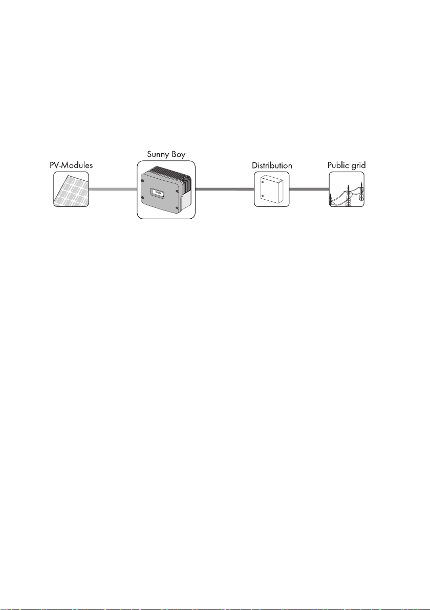
2.1 Intended Use
The Sunny Boy is a PV inverter which converts the DC current of the PV array to AC current and feeds
it into the power distribution grid.
Principle of a PV plant with this Sunny Boy
The Sunny Boy may only be operated with PV arrays (PV modules and cabling) of protection class II.
Do not connect any sources of energy other than PV modules to the Sunny Boy.
When designing the PV plant, ensure that the values comply with the permitted operating range of all
components at all times. The free design program "Sunny Design" (www.SMA.de/en/SunnyDesign)
will assist you. The manufacturer of the PV modules must have approved the modules for use with this
Sunny Boy. You must also ensure that all measures recommended by the module manufacturer for
long-term maintenance of the module properties are taken (see also Technical Information "Module
Technology" in the download area of www.SMA.de/en).
Do not use the Sunny Boy for purposes other than those described here. Alternative uses,
modifications to the Sunny Boy or the installation of component parts not expressly recommended or
sold by SMA Solar Technology AG shall void any warranty claims and the operation permission.
Installation Manual SB33-38-11-IA-en-62 9
Page 10
Safety SMA Solar Technology AG
2.2 Safety Precautions
DANGER!
Danger to life due to high voltages in the inverter
• All work on the inverter may only be carried out by an electrically qualified person.
• Physically or mentally challenged persons may only perform activities on the inverter
following proper instruction and under supervision.
• Children must not play with the inverter. Children must not have access to an inverter
in operation.
WARNING!
Risk of electric shock when pulling out the DC connectors under load
If you disconnect the DC connectors from the inverter under load, an electric arc may
occur, leading to electric shock and burns.
• If the inverter is not equipped with an Electronic Solar Switch and the regulations
valid at the installation site require an external DC switch-disconnector, install an
external DC switch-disconnector.
• Switch off the DC connector, the AC miniature circuit-breaker and disconnect the
inverter on the DC side before pulling out the DC connectors.
CAUTION!
Risk of burns due to hot enclosure parts
• Do not touch the inverter's enclosure during operation.
NOTICE!
Dust and water intrusion can damage the inverter.
If the inverter is equipped with an Electronic Solar Switch, it will only provide IP21 degree
of protection once the Electronic Solar Switch has been pulled out. The inverter is therefore
no longer protected against water and dust intrusion. In order to maintain the degree of
protection IP65 also during temporary decommissioning, proceed as follows:
• Unlock and disconnect all DC connectors.
• Open all DC connectors and remove the cables.
• Close all DC inputs with the corresponding DC connectors and the supplied sealing
plugs.
• Firmly connect the Electronic Solar Switch again.
10 SB33-38-11-IA-en-62 Installation Manual
Page 11
SMA Solar Technology AG Safety
NOTICE!
Damage to the inverter due to moisture and dust intrusion
If the Electronic Solar Switch is not plugged in or incorrectly plugged in during operation,
moisture and dust can penetrate the inverter.
If the Electronic Solar Switch is not correctly plugged in, this can cause contacts to wear in
the Electronic Solar Switch or the Electronic Solar Switch might fall down. This can result in
yield loss and damage to the Electronic Solar Switch.
Always plug in the Electronic Solar Switch as described in the following:
• Do not tighten the screw in the Electronic Solar Switch.
• Firmly plug in the Electronic Solar Switch until it is flush with the enclosure.
• Ensure that the maximum distance between the Electronic Solar Switch and the
enclosure is 1 mm.
PV array grounding
Comply with local regulations for the grounding the PV modules and of the PV array.
SMA Solar Technology AG recommends connecting the PV array frame and other
electrically conductive surfaces so that there is continuous conduction and to ground them
in order to ensure maximum protection for plants and persons.
Installation Manual SB33-38-11-IA-en-62 11
Page 12
Safety SMA Solar Technology AG
DC
21
2.3 Explanation of Symbols
This section gives an explanation of all the symbols found on the inverter and on the type label.
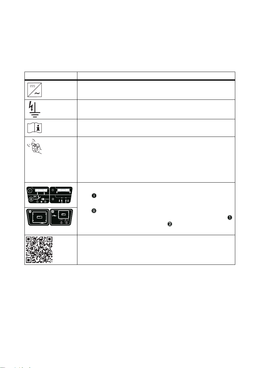
2.3.1 Symbols on the Inverter
Symbol Explanation
Operation display.
Indicates the operating state of the inverter.
Ground fault or varistor defective.
Read section 9.3"Red LED is Glowing Continuously" (page56).
Fault or disturbance.
Read section 9"Troubleshooting" (page50).
You can operate the display by tapping the enclosure lid:
• Tapping once: the backlight switches on or the display scrolls to the
next display message.
• Tapping twice in quick succession*: The inverter shows the display
messages from the startup phase again (see section 6.2"Display
Messages During the Startup Phase" (page40)).
DC switch-disconnector Electronic Solar Switch (ESS)**
• When the Electronic Solar Switch is plugged in,
the DC electric circuit is closed.
• In order to interrupt the DC electric circuit and disconnect the
inverter safely under load, first pull out the Electronic Solar Swit ch
and then remove all DC connectors as described in section
7.2"Opening the Inverter" (page41).
QR-Code
You will find information on the SMA bonus program at
www.SMA-Bonus.com.
®
*** for SMA bonus program
* This function is valid from firmware version 4.00
** optional
*** QR-Code is a registered trademark of DENSO WAVE INCORPORATED.
12 SB33-38-11-IA-en-62 Installation Manual
Page 13
SMA Solar Technology AG Safety
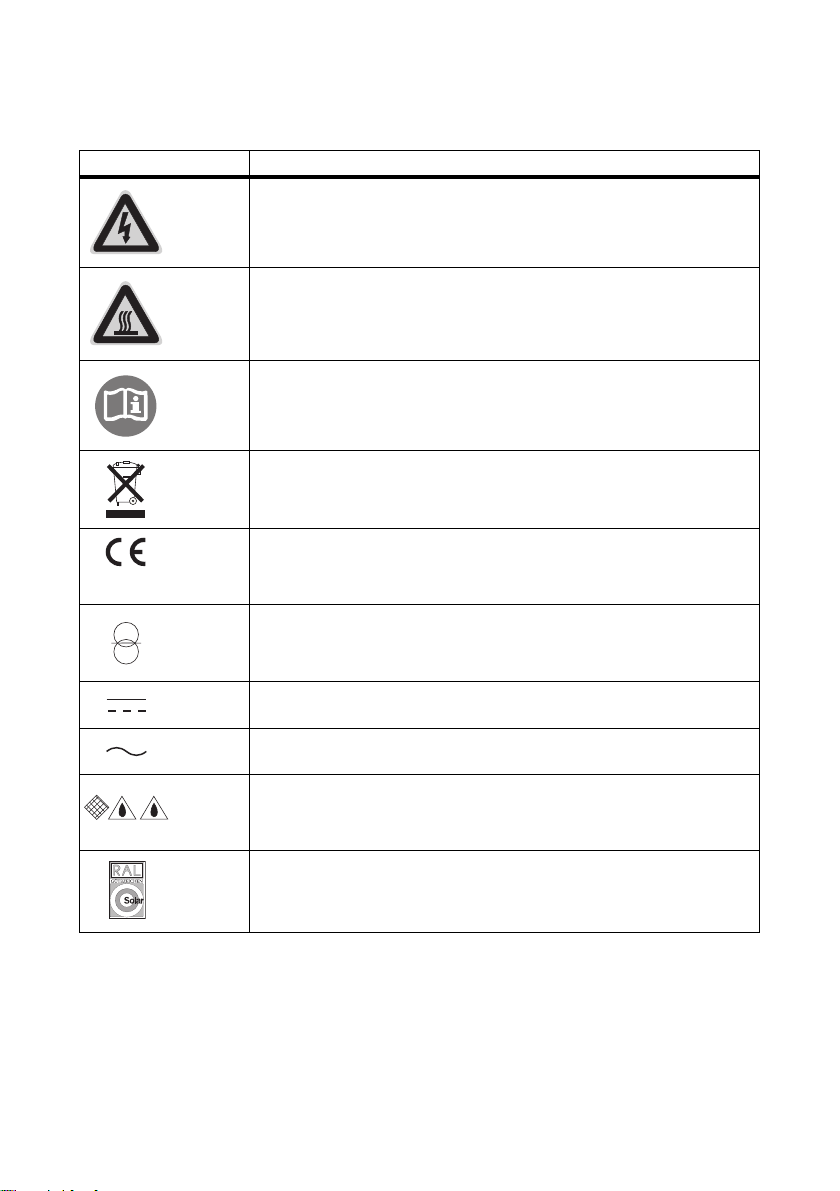
2.3.2 Symbols on the Type Label
Symbol Explanation
Beware of hazardous voltage.
The inverter operates at high voltages. All work on the inverter may only be
carried out by an electrically qualified person.
Beware of hot surface.
The inverter can become hot during operation. Avoid contact during
operation.
Observe all documentation that accompanies the inverter.
The inverter must not be disposed of together with the household waste.
For more information on disposal, see section 10.4"Disposing of the
Inverter" (page63).
CE marking.
The inverter complies with the requirements of the applicable
EC guidelines.
The inverter has a transformer.
Direct current (DC)
Alternating current (AC)
Degree of protection IP65
The inverter is protected against dust intrusion and water jets from any
angle.
RAL quality mark for solar products.
The inverter complies with the requirements of the German Institute for
Quality Assurance and Certification.
Installation Manual SB33-38-11-IA-en-62 13
Page 14
Unpacking SMA Solar Technology AG
3 Unpacking
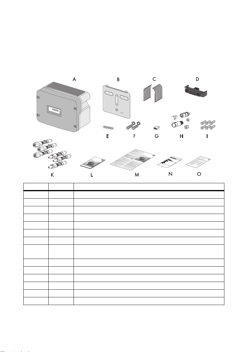
3.1 Scope of Delivery
Check the delivery for completeness and for visible external damage, such as cracks in the enclosure
or in the display. Contact your specialty retailer if anything is damaged or missing.
Object Quantity Description
A 1 Sunny Boy
B 1 Wall mounting bracket
C 2 Ventilation grids (right/left)
D 1 DC load disconnection unit Electronic Solar Switch (ESS)*
E 5Filler plugs
F 2 Cheese-head screws and M6 conical spring washers
G 1Jumper
H 1 AC coupling socket: socket unit, protective cap for socket unit, threaded
sleeve, sealing ring, pressure screw
I 6 Sealing plugs
K 6 (4) DC connectors (3 ⨯ positive, 3 ⨯ negative)**
L 1 Installation manual
M 1User manual
N 1Document set
O 1 Supplementary sheet with default settings
* optional
** For inverters without ESS: 2 ⨯ positive, 2 ⨯ negative
14 SB33-38-11-IA-en-62 Installation Manual
Page 15

SMA Solar Technology AG Unpacking
3.2 Identifying the Inverter
You can identify the inverter using the type label. The type label is on the right-hand side of the
enclosure.
The serial number (Serial No.) and the type (Type / Model) of the inverter, as well as device-specific
characteristics, are specified on the type label.
Installation Manual SB33-38-11-IA-en-62 15
Page 16
Mounting SMA Solar Technology AG
4 Mounting
4.1 Safety
DANGER!
Danger to life due to fire or explosion.
Despite careful construction, electrical devices can cause fires.
• Do not mount the inverter on flammable construction materials.
• Do not mount the inverter in areas where highly flammable materials are stored.
• Do not mount the inverter in a potentially explosive atmosphere.
CAUTION!
Risk of burns due to hot enclosure parts
• Mount the inverter in such a way that it cannot be touched inadvertently during
operation.
CAUTION!
Risk of injury due to the heavy weight of the inverter.
• Take the inverter's weight of approx. 38 kg into account for mounting.
4.2 Selecting the Mounting Location
Consider the following requirements when selecting the mounting location:
• The mounting method and location must be suitable for the inverter's weight and dimensions
(see section 11"Technical Data" (page64)).
• Mount on a solid surface.
• The mounting location must at all times be clear and safely accessible without the use of
additional aids such as scaffolding or lifting platforms. Non-fulfillment of these criteria may
restrict servicing.
16 SB33-38-11-IA-en-62 Installation Manual
Page 17
SMA Solar Technology AG Mounting
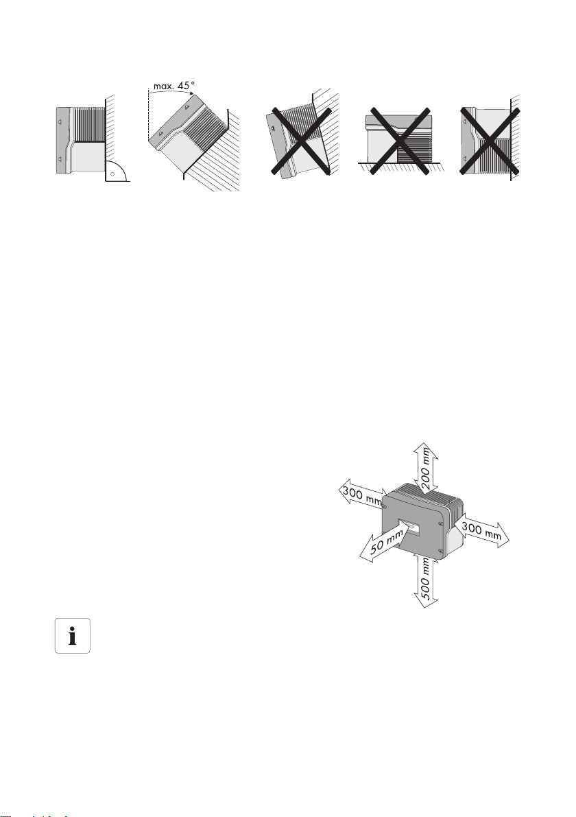
• Mount vertically or tilted backwards at a maximum angle of 45°.
• The connection area must point downward.
• Never mount the device with a forward tilt.
• Never mount the device with a sideways tilt.
• Do not mount horizontally.
• Install at eye level in order to allow operation states to be read at all times.
• The inverter must be easy to remove from the mounting location at any time.
• The ambient temperature should be below 40°C to ensure optimum operation.
• Do not expose the inverter to direct solar irradiation as this can cause excessive heating and
thus power reduction.
• I n li vin g areas , do not mou nt t he u nit on p las ter boa rd walls or similar to avoid audible vibrations.
The inverter can make noises when in use which may be perceived as a nuisance in a living
area.
• Observe the minimum clearances to walls, other
inverters, or objects as shown in the diagram in
order to ensure sufficient heat dissipation and,
if applicable, sufficient space for removing the
Electronic Solar Switch if included.
Multiple inverters installed in areas with high ambient temperatures
If necessary, increase the clearances between the individual inverters. In addition, make
sure there is enough fresh-air supply to ensure sufficient cooling of the inverters.
Installation Manual SB33-38-11-IA-en-62 17
Page 18
Mounting SMA Solar Technology AG
4.3 Mounting the Inverter with the Wall Mounting Bracket
CAUTION!
Risk of injury due to the heavy weight of the inverter.
• Note that the inverter weighs approx. 38 kg.
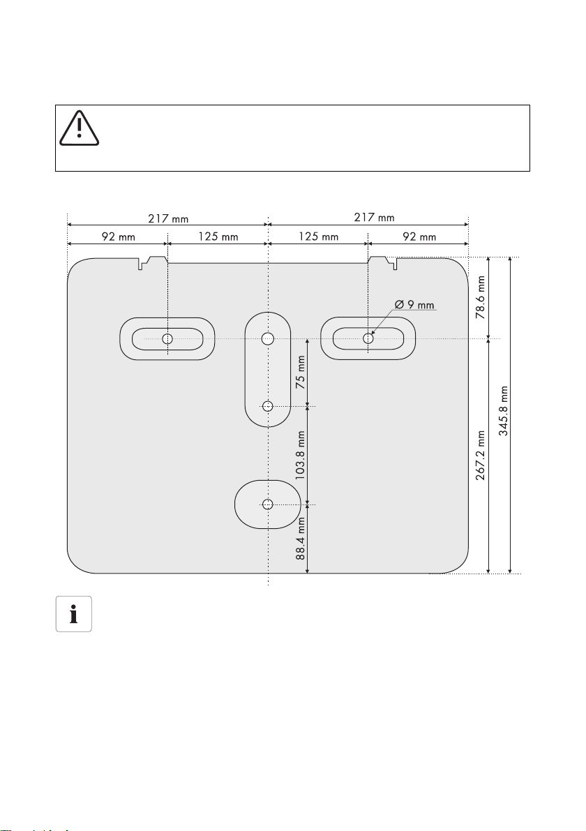
1. Use the wall mounting bracket as a drilling template and mark the positions of the drill holes.
Mounting material
When mounting the wall mounting bracket, use fastening material suitable for the mounting
surface.
2. Fill in holes that are not required in the wall mounting bracket using the filler plugs.
Plug the filler plugs into the wall mounting bracket from the side that will later be facing the wall.
18 SB33-38-11-IA-en-62 Installation Manual
Page 19
SMA Solar Technology AG Mounting
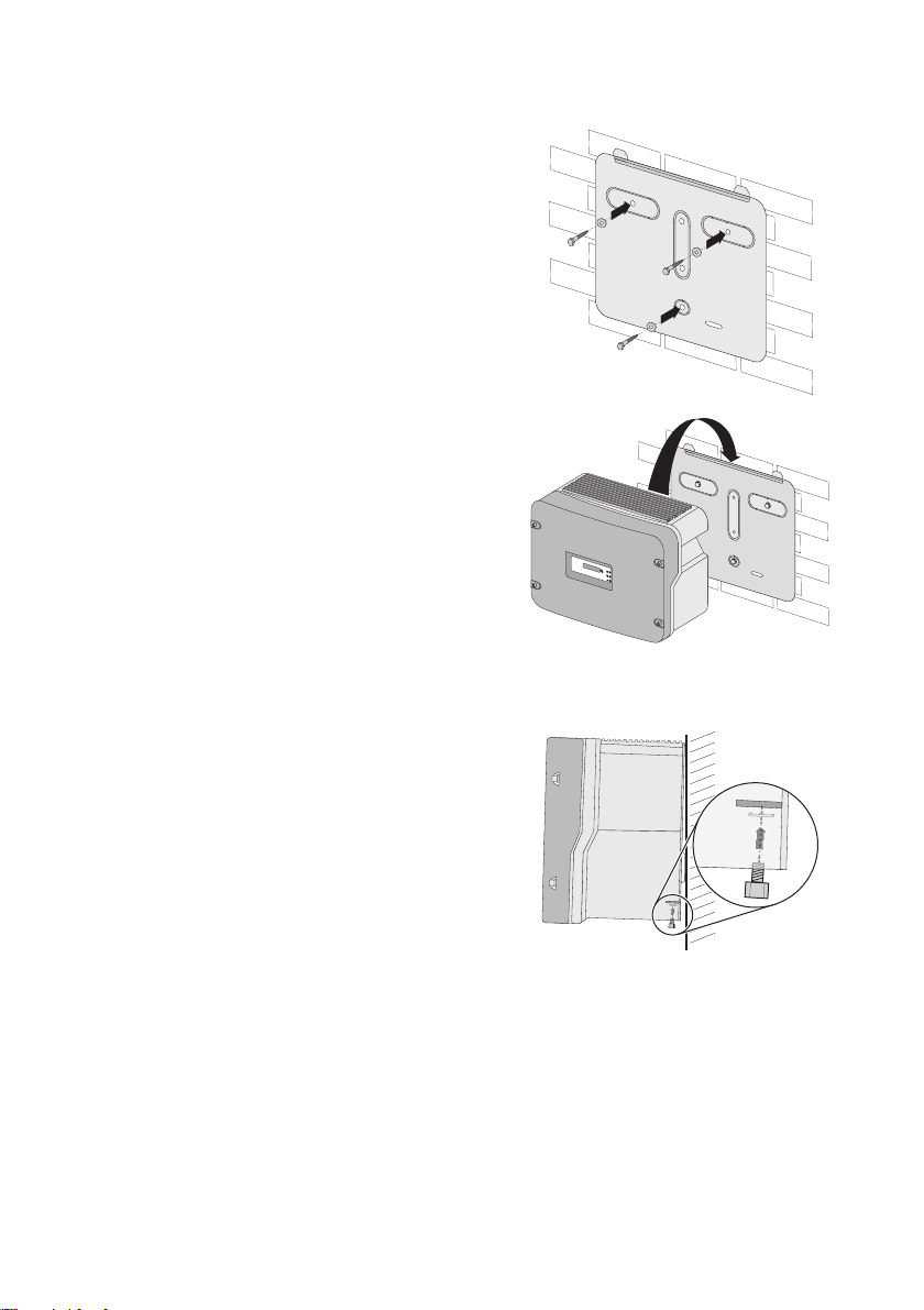
3. Attach the wall mounting bracket to the wall using
appropriate screws and washers.
4. Hang the inverter in the wall mounting bracket. In
doing so, lead the anchorage brackets through the
cut-outs on in the inverter.
☑ Both brackets of the wall mounting bracket
extrude out of the cut-outs on the inverter.
5. If a second protective conductor is required, ground the inverter and secure against being
pulled out (5.3.3"Connecting Additional Grounding" (page28)).
6. If a second protective conductor is not required,
secure the inverter against being pulled out:
– Plug the cheese-head screw with conical spring
washer through the metal shackle on the
underside of the enclosure. The teeth of the
conical spring washer must be facing the metal
shackle.
– Tighten the cheese-head screw to a torque of
6 Nm.
7. Check to ensure that the inverter is securely in place. The wall mounting bracket is designed in
such way that the inverter tilts backward slightly on a perfectly vertical wall.
Installation Manual SB33-38-11-IA-en-62 19
Page 20
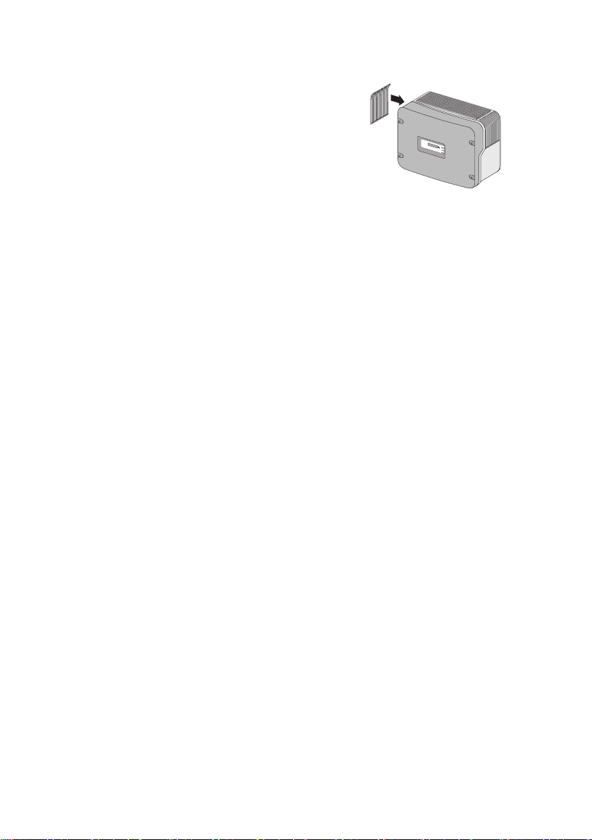
Mounting SMA Solar Technology AG
8. Attach the ventilation grids. These are labelled with
"links/left" or "rechts/right".
20 SB33-38-11-IA-en-62 Installation Manual
Page 21
SMA Solar Technology AG Electrical Connection
5 Electrical Connection
5.1 Safety
NOTICE!
Electrostatic discharges can damage the inverter.
Internal component parts of the inverter can be irreparably damaged by static electric
discharge.
• Before you touch a component inside the inverter, ground yourself by touching a
grounded object.
5.2 Overview of the Connection Area
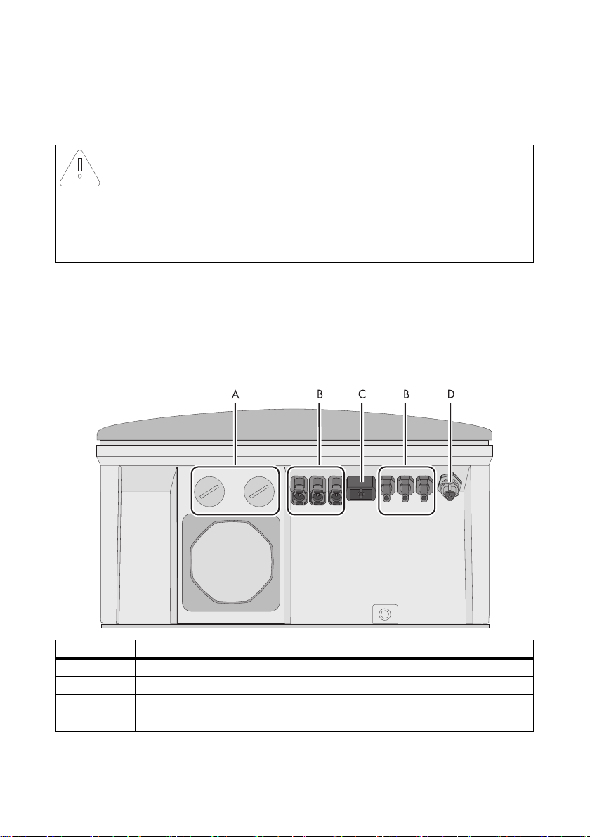
5.2.1 Exterior View
The following figure shows the assignment of the individual connection areas on the bottom of the
inverter.
Object Description
A Enclosure openings for communication (with filler-plugs)
B DC connectors for connecting the PV strings*
C Jack for connecting the DC switch-disconnector Electronic Solar Switch (ESS)**
D AC socket for grid connection
*If you have ordered the inverter without ESS, the inverter is fitted with 2 negative and 2 positive DC connectors.
** optional
Installation Manual SB33-38-11-IA-en-62 21
Page 22
Electrical Connection SMA Solar Technology AG
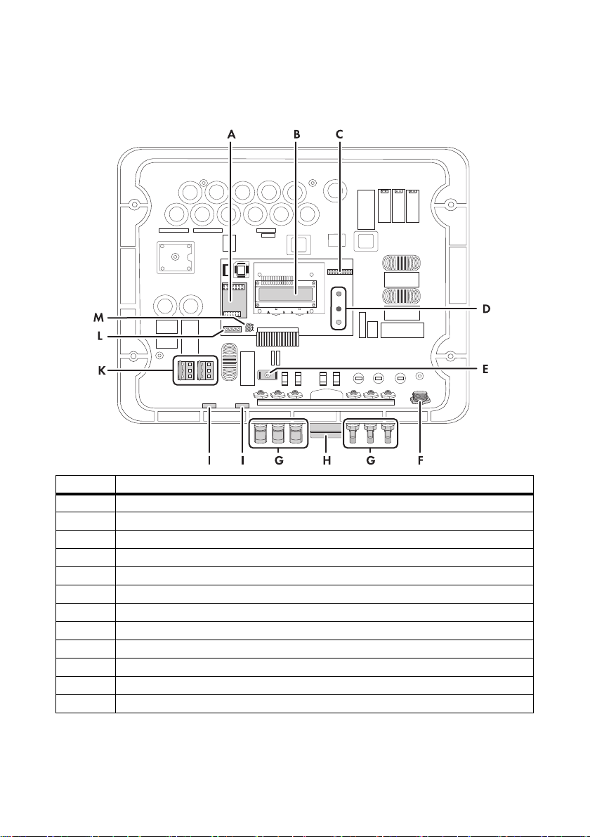
5.2.2 Interior View
The following figure shows the various components and connection areas of the open inverter.
Object Description
A Slot for communication
B Display
C Jumper slot for fan test
D Operating status LEDs
E Flat male tab for grounding the cable shield with cable-bound communication
F AC socket for grid connection
G DC connectors for connecting the PV strings*
H Jack for the Electronic Solar Switch (ESS)**
I Enclosure opening with filler-plug for communication.
K Varistors
L Communication connection
M Jumper slot for communication
*If you have ordered the inverter without ESS, the inverter is fitted with 2 negative and 2 positive DC connectors.
** optional
22 SB33-38-11-IA-en-62 Installation Manual
Page 23
SMA Solar Technology AG Electrical Connection
5.3 Connection to the Power Distribution Grid (AC)
5.3.1 Conditions for the AC Connection
Connection requirements of the grid operator
Always observe the connection requirements of your grid operator.
Cable Design
Use "Sunny Design" version 2.0 or higher for the dimensioning of the conductor cross-sectional areas
(see "Sunny Design" design program at www.SMA.de/en).
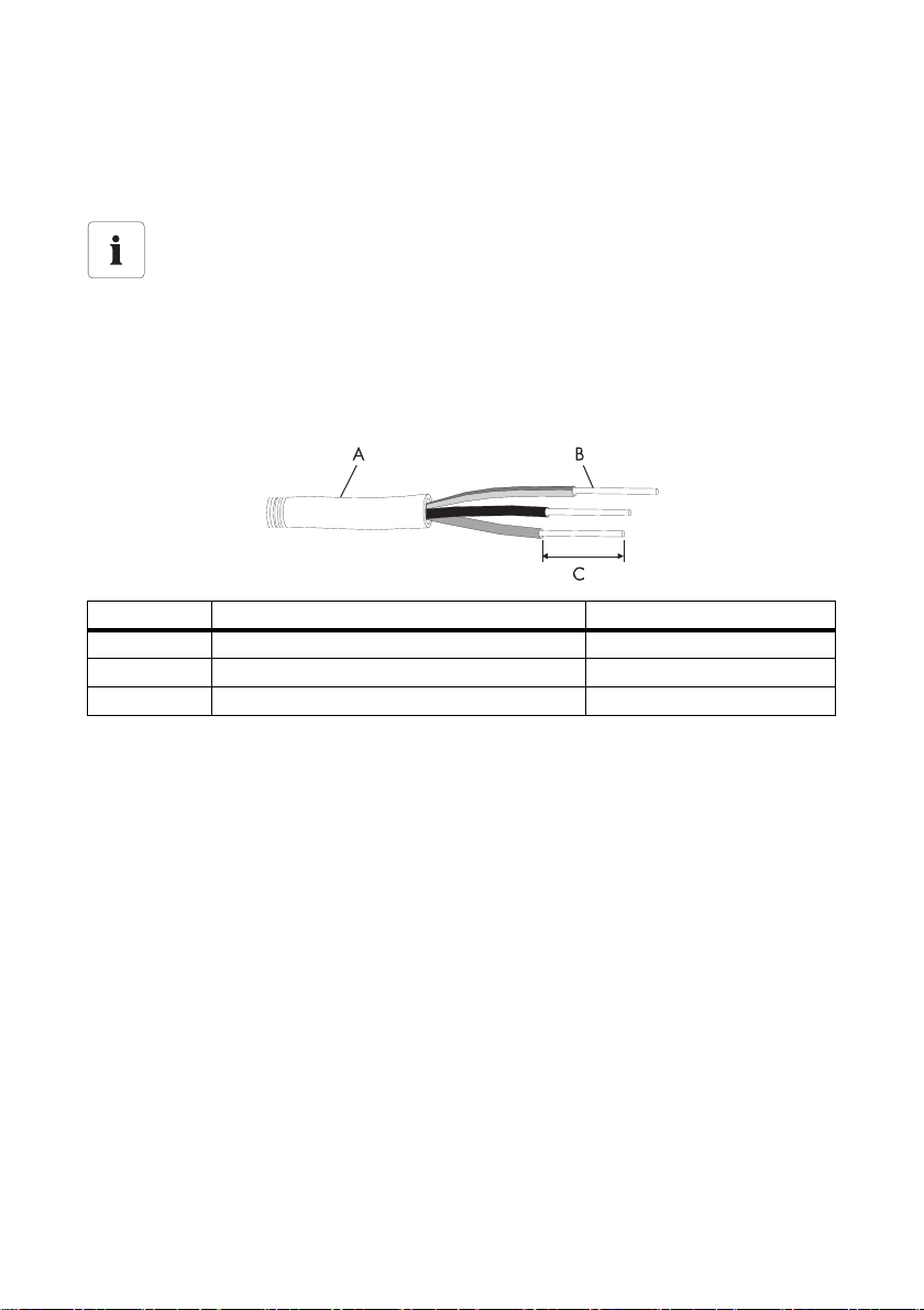
Cable Requirements
Position Designation Value
A External diameter 6 mm ... 14 mm
B Conductor cross-section 4 mm²
C Length of insulation to be stripped off 8 mm
Installation Manual SB33-38-11-IA-en-62 23
Page 24

Electrical Connection SMA Solar Technology AG
Load Disconnection Unit
You must install a separate miniature circuit-breaker for each inverter in order to ensure that the
inverter can be securely disconnected under load. The maximum permissible fuse protection can be
found in section 11"Technical Data" (page64).
Detailed information and examples for the rating of a miniature circuit-breaker can be found in the
Technical Information "Miniature Circuit-Breaker" in the SMA Solar Technology AG download area
at www.SMA.de/en.
DANGER!
Danger to life due to fire.
When more than 1 inverter is connected in parallel to the same miniature circuit-breaker,
the protective function of the miniature circuit-breaker is no longer guaranteed. It can result
in a cable fire or destruction of the inverter.
• Never connect several inverters to a single miniature circuit-breaker.
• Observe the maximum permissible fuse protection of the inverter when selecting the
miniature circuit-breaker.
DANGER!
Danger to life due to fire.
When a generator (inverter) and a load are connected to the same miniature
circuit-breaker, the protective function of the miniature circuit-breaker is no longer
guaranteed. The currents from the inverter and the power distribution grid can accumulate
to overcurrent which is not detected by the miniature circuit-breaker.
• Never connect loads between the
inverter and the miniature circuit-breaker
without fuse protection.
• Always protect loads separately.
NOTICE!
Damage to the inverter by using screw type fuses as a load disconnection unit.
A s cre w ty pe f use , e. g. D IAZ ED f use or N EOZ ED f use , is not a sw itch-disconnector and thus
may not be used as a load disconnection unit. A screw type fuse only acts as cable
protection.
When disconnecting under load using a screw type fuse, the inverter can be damaged.
• Use o nly a switch-di sconnecto r or a mi niature circui t-breaker as a l oad dis conne ction
unit.
24 SB33-38-11-IA-en-62 Installation Manual
Page 25

SMA Solar Technology AG Electrical Connection
5.3.2 Connecting the Inverter to the Power Distribution Grid (AC)
Overview of the AC Connection Socket
Object Description
A Protective cap for socket element
B Jack element
C Threaded sleeve with sealing ring for cable diameters of 10 mm to 14 mm
D Sealing ring for cable diameters of 6 mm to 10 mm
E Pressure screw
Procedure
1. Check the line voltage and compare with "V
The exact operating range of the inverter is specified in the operating parameters.
The corresponding document can be found in the download area at www.SMA.de/en,
in the "Technical Description" category of the respective inverter.
2. Disconnect the miniature circuit-breaker and secure against re-connection.
3. If necessary, exchange the sealing ring of the threaded sleeve with the sealing ring provided.
– Pull the sealing ring out of the threaded sleeve.
– Insert the smaller sealing ring.
4. Pass the pressure screw (E) over the AC cable.
" on the type label.
AC nom
Installation Manual SB33-38-11-IA-en-62 25
Page 26

Electrical Connection SMA Solar Technology AG
5. Pass the threaded sleeve (C) with the sealing ring over the AC cable.
6. Bend the AC cable. The bending radius must be at
least four times the cable diameter.
7. Shorten the cable.
8. Shorten phase L and neutral conductor N
4 to 5 mm.
9. Insert the PE protective conductor (green-yellow)
into the screw terminal with the earth sign on the
socket element and tighten the screw.
The PE protective conductor must be longer than the
insulated conductors of N and L.
10. Insert the neutral conductor N (blue) into the screw
terminal N on the jack element and tighten the
screw.
11. Insert phase L (brown or black) into screw terminal
L on the jack element and tighten the screw.
12. Make sure the insulated conductors are securely
connected.
13. Push the threaded sleeve (C) onto the jack element (B) until it audibly snaps into place.
26 SB33-38-11-IA-en-62 Installation Manual
Page 27

SMA Solar Technology AG Electrical Connection
14. Screw the pressure screw (E) tightly onto the threaded sleeve (C).
The pressure screw serves to seal and relieve strain.
☑ The AC connection socket has been screwed together.
15. Close the socket element with the protective cap provided, if the inverter has not yet been
connected.
16. Insert the AC connection socket into the AC socket
on the inverter. Remove the protective cap
beforehand, if required.
☑ The AC cable is connected to the inverter.
A
DANGER!
Danger to life due to high voltages in the inverter.
• Do not switch on the miniature circuit-breaker until the PV array has been connected
and the inverter is securely closed.
Installation Manual SB33-38-11-IA-en-62 27
Page 28

Electrical Connection SMA Solar Technology AG
5.3.3 Connecting Additional Grounding
If a second protective conductor, additional grounding or equipotential bonding is required,
you can additionally ground the inverter on the enclosure.
Overview of the Additional Grounding
Object Description
A Metal shackle on the bottom of the inverter enclosure
B Conical spring washer (included in the scope of delivery)
C Terminal lug (M6) with protective conductor
D Washer
E M6x12 cheese-head screw (included in the scope of delivery)
Procedure
1. Disconnect the inverter from the AC and DC side as described in section 7.2"Opening the
Inverter" (page41).
2. Align washer, terminal lug with protective
conductor and conical spring washer on cheesehead screw. The teeth of the conical spring washer
must be facing the metal shackle.
3. Plug the cheese-head screw into the metal shackle
and tighten to a torque of 6 Nm.
4. Check that the contact between the protective conductor and the enclosure is in accordance
with the regulations valid for the country of installation.
28 SB33-38-11-IA-en-62 Installation Manual
Page 29

SMA Solar Technology AG Electrical Connection
5.4 Setting the Display Language
You can set the language of the display using the switches at the bott om of the dis pla y as sembly i nsi de
the inverter.
Procedure
1. Open the inverter as described in section 7.2"Opening the Inverter" (page41).
2. Set the switches to the required language, as
shown below. The following switch settings apply:
Language Switch S2 Switch S1
German B B
English B A
French A B
Spanish A A
3. Close the inverter as described in section
7.3"Closing the Inverter" (page43).
☑ The display language is set.
Installation Manual SB33-38-11-IA-en-62 29
Page 30

Electrical Connection SMA Solar Technology AG
5.5 Connecting the PV Array (DC)
5.5.1 Conditions for the DC Connection
Use of Y adapters for parallel connection of strings
Y adapters may not be visible within close proximity of the inverter or freely accessible.
• The DC electric circuit must not be interrupted by adapters.
• Observe the procedure for disconnecting the inverter as described in section
7.2"Opening the Inverter" (page41).
• Requirements for the PV modules of the connected strings:
– Same type
– Same quantity
– Identical alignment
– Identical tilt
• The connecting cables of the PV modules must be equipped with connectors.
The DC connectors for the DC connection are included in the delivery.
• If the inverter is not equipped with an Electronic Solar Switch and the regulations valid at the
installation site require an external DC switch-disconnector, install an external DC switchdisconnector.
• The following limiting values at the DC input of the inverter must not be exceeded:
Maximum input voltage Maximum input current
500 V (DC) 20 A (DC)
DANGER!
Risk of lethal electric shock or fire.
The maximum possible input current per string is limited by the connectors used.
If the connectors are overloaded, an electric arc may occur and there is a risk of fire.
• Ensure that the input current for each string does not exceed the maximum throughfault current of the connectors used.
30 SB33-38-11-IA-en-62 Installation Manual
Page 31

SMA Solar Technology AG Electrical Connection
5.5.2 Assembling the DC Connectors
For connection to the inverter, all connection cables of the PV modules must be equipped with the
DC connectors provided.
To assemble the DC connectors, proceed as follows. Ensure the connectors have the correct polarity.
The DC connectors have the symbols "+" and "‒".
Cable requirements:
• Use a PV1-F cable.
Procedure
1. Lead the stripped cable all the way into the
DC connector.
2. Press the clamping bracket down.
☑ The clamping bracket snaps audibly into place.
3. Ensure that the cable is correctly positioned:
Result Measure
☑ If the stranded wire is visible in the chamber
of the clamping bracket, the cable is
correctly positioned.
Installation Manual SB33-38-11-IA-en-62 31
• Proceed to step 4.
Page 32

Electrical Connection SMA Solar Technology AG
Result Measure
☑ If the stranded wire is not visible in the
chamber, the cable is not correctly
positioned.
• Loosen the clamping bracket. To do so,
insert a screwdriver into the clamping
bracket and lever the clamping bracket out
(blade width 3.5 mm).
• Remove the cable and go back to step 1.
4. Push the cable gland to the thread and tighten it (torque: 2 Nm).
☑ The DC connectors are assembled and can now be connected to the inverter as described in
section 5.5"Connecting the PV Array (DC)" (page30).
32 SB33-38-11-IA-en-62 Installation Manual
Page 33

SMA Solar Technology AG Electrical Connection
5.5.3 Opening the DC Connector
1. Unscrew the screw connection.
2. Unlock the DC connector. To do this insert a
screwdriver into the side catch mechanism and
lever out (blade width 3.5 mm).
3. Carefully pull the DC connector apart.
4. Loosen the clamping bracket. To do so, insert a
screwdriver into the clamping bracket and lever the
clamping bracket out (blade width 3.5 mm).
5. Remove the cable.
☑ The cable is removed from the DC connector.
Installation Manual SB33-38-11-IA-en-62 33
Page 34

Electrical Connection SMA Solar Technology AG
5.5.4 Connecting the PV Array (DC)
DANGER!
Danger to life due to high voltage at the inverter
• Before connecting the PV array, switch off the miniature circuit-breaker and make
sure that it cannot be reconnected.
NOTICE!
Excessive voltages can destroy the measuring device.
• Only use measuring devices with a DC input voltage range up to at least 1 000 V.
1. Disconnect the miniature circuit-breaker and secure against re-connection.
2. If an Electronic Solar Switch is installed, pull it
downwards, slightly towards the wall.
3. Check the connection cables of the PV modules for
correct polarity and make sure that the maximum
input voltage of the inverter is not exceeded.
With an ambient temperature over 10°C, the openci rcu it v olt age of t he P V mo dul es s hou ld n ot e xce ed
90% of the maximum input voltage of the inverter.
Otherwise, check the plant design and the
PV module connection. If this is not done, the
maximum inverter input voltage can be exceeded
at low ambient temperatures.
NOTICE!
Exceeding the maximum input voltage can destroy the inverter.
If the voltage of the PV modules exceeds the maximum input voltage of the inverter, it can
be destroyed by the overvoltage. This will void all warranty claims.
• Do not connect strings with an open-circuit voltage greater than the maximum input
voltage of the inverter.
• Check the plant design.
34 SB33-38-11-IA-en-62 Installation Manual
Page 35

SMA Solar Technology AG Electrical Connection
+
1
2
+
4. Check the strings for ground faults as described in section 9.3.1"Checking the PV Array for
Ground Faults" (page56).
NOTICE!
Excessive currents can damage the inverter
• The maximum current per DC connector may not exceed 16 A.
5. Connect the assembled DC connectors to the inverter.
☑ The DC connectors click audibly into position.
To release the DC connectors, see section 7.2"Opening the Inverter" (page41).
6. In order to seal the inverter, all the DC inputs that are not required have to be closed with
DC connectors and sealing plugs:
Sealing plugs
•Do not plug the sealing plugs directly into the DC inputs on the inverter.
– For unused DC connectors, push down the
clamping bracket and push it onto the cable
gland.
– Plug the sealing plug into the DC connector.
Installation Manual SB33-38-11-IA-en-62 35
Page 36

Electrical Connection SMA Solar Technology AG
+
– Tighten the DC connector (torque: 2 Nm).
– Insert the DC connectors with sealing plugs into
the corresponding DC inputs on the inverter.
☑ The DC connectors click audibly into position.
7. Ensure that all DC connectors are securely in place.
8. If an Electronic Solar Switch is installed, check it for
wear, as described in section 8.3"Checking the
Electronic Solar Switch for Wear" (page49), and
reattach it firmly.
NOTICE!
Damage to the inverter due to moisture and dust intrusion
If the Electronic Solar Switch is not plugged in or incorrectly plugged in during operation,
moisture and dust can penetrate the inverter.
If the Electronic Solar Switch is not correctly plugged in, this can cause contacts to wear in
the Electronic Solar Switch or the Electronic Solar Switch might fall down. This can result in
yield loss and damage to the Electronic Solar Switch.
Always plug in the Electronic Solar Switch as described in the following:
• Do not tighten the screw in the Electronic Solar Switch.
• Firmly plug in the Electronic Solar Switch until it is flush with the enclosure.
• Ensure that the maximum distance between the Electronic Solar Switch and the
enclosure is 1 mm.
☑ The PV array is connected.
36 SB33-38-11-IA-en-62 Installation Manual
Page 37

SMA Solar Technology AG Electrical Connection
5.6 Communication
The inverter is equipped with a slot for communication interfaces in order to communicate with special
data loggers (e.g., Sunny WebBox) or a PC with corresponding software
(e.g., Sunny Data Control or Sunny Explorer).
Refer to the respective communication interface manual for a detailed wiring diagram and an
installation description for the interface.
The inverter's active power can be limited or the displacement power factor cos φ can be set
externally using the Power Reducer Box from SMA Solar Technology AG. You will find detailed
information on active power limitation and on setting the displacement power factor cos φ in the
Technical Description "Operating Parameters" at www.SMA.de/en.
Installation Manual SB33-38-11-IA-en-62 37
Page 38

Electrical Connection SMA Solar Technology AG
5.7 Setting the Grid and Country Parameters
Changing grid-relevant and country parameters
To change grid-relevant parameters, you need a personal access code – the so-called
SMA Grid Guard Code. The application form for the personal access code is available in
the download area at www.SMA.de/en, in the "Certificate" category of the respective
inverter. Ensure that you discuss the changes to these parameters with your grid operator.
A detailed description of the operating parameters for the inverter is available in the download area
at www.SMA.de/en in the category "Technical Description" of the respective inverter.
5.7.1 Setting the Installation Country
Using the "Default" parameter, you can set the installation country and/or the grid connection
standard valid for the country via a communication product (e.g., Sunny WebBox) or a PC with
corresponding software (e.g., Sunny Data Control or Sunny Explorer). This, however, is only required
if the inverter was originally ordered for another country. You can see the standard to which the
inverter was set upon delivery on the type label and on the included supplementary sheet with the
default settings.
5.7.2 Setting Stand-alone Grid Operation
To operate the inverter in an off-grid system with Sunny Island, you must set the inverter via the
"Default" parameter to stand-alone grid operation ("OFF-Grid").
You have several possibilities to set the inverter to stand-alone grid operation:
• Setting via Sunny WebBox
or
• Setting via Sunny Data Control or Sunny Explorer
DANGER!
Danger to life due to high voltages in the event of outage of the power
distribution grid.
If you set the inverter to stand-alone grid operation, it does not fulfill any country-specific
standards and guidelines. If there is a power distribution grid outage, there is consequently
a danger of back-feed.
• Never operate the inverter directly on the power distribution grid when set to
stand-alone grid operation.
38 SB33-38-11-IA-en-62 Installation Manual
Page 39

SMA Solar Technology AG Commissioning
6 Commissioning
6.1 Commissioning the Inverter
1. Check the following requirements before commissioning:
– The inverter is securely in place.
– The AC cables are correctly connected (power distribution grid).
– All DC cables are completely connected (PV strings).
– Unused DC inputs are closed using the corresponding DC connectors and sealing plugs.
– The enclosure lid is securely screwed in place.
– An external DC switch-disconnector is additionally connected or, if available,
the Electronic Solar Switch (ESS) is firmly in place.
– The miniature circuit-breaker is correctly laid out.
2. Switch on the miniature circuit-breaker.
☑ All 3 LEDs are glowing or flashing: the startup phase is starting.
☑ Green LED is glowing: commissioning was successful.
or
☑ Green LED flashes in case of insufficient irradiation: Grid connection conditions have not yet
been reached. Wait for sufficient irradiation.
or
☑ The red or yellow LED is glowing or flashing: a disturbance has occurred. Proceed to step 3.
A Green LED Operation
B Red LED Ground fault or varistor
defective
C Yellow LED Fault
3. Read section 9"Troubleshooting" (page50) and if necessary, eliminate the error or fault.
Installation Manual SB33-38-11-IA-en-62 39
Page 40

Commissioning SMA Solar Technology AG
SB xxx
Wrxxx
6.2 Display Messages During the Startup Phase
• After commissioning, the inverter displays the
device type in the startup phase.
• After 5 seconds or when you tap again on the
enclosure lid, the firmware version of the internal
processors is displayed by the inverter.
• After a further 5 seconds or when you tap again,
th e co nfi gur ed c oun try stan dar d is dis pla yed by t he
inverter (example: "VDE-AR-N4105-MP").
Showing the display messages again (valid as of firmware version 4.00)
If you want to view the display messages of the startup phase again while in normal
operation, tap the enclosure lid twice in quick succession.
40 SB33-38-11-IA-en-62 Installation Manual
Page 41

SMA Solar Technology AG Opening and Closing
7 Opening and Closing
7.1 Safety
DANGER!
Risk of lethal electric shock.
Before opening the inverter, observe the following:
• Ensure that no voltage is present on the AC side.
• Ensure that neither voltage nor current is present on the DC side.
NOTICE!
Static discharges can damage the inverter.
The internal component parts of the inverter can be irreparably damaged by electrostatic
discharge.
• Ground yourself before touching a component part.
7.2 Opening the Inverter
1. Disconnect the miniature circuit-breaker and secure against re-connection.
2. If an external DC switch-disconnector is present, disconnect the external DC
switch-disconnector.
3. If an Electronic Solar Switch is installed, pull it
downwards, slightly towards the wall.
4. Using a current probe, ensure that no current is
present at any of the DC cables.
☑ If current is present, check the installation.
Installation Manual SB33-38-11-IA-en-62 41
Page 42

Opening and Closing SMA Solar Technology AG
5. Unlock and disconnect all DC connectors. To do
this, insert the screwdriver into one of the side slots
(blade width: 3.5 mm) and pull the DC connectors
straight down.
Do not pull on the cable while doing this.
☑ All DC connectors are disconnected from the
inverter. The inverter is entirely disconnected
from the PV array.
6. Pull out the AC plug.
7. Check whether all LEDs and the display have gone out.
DANGER!
Danger to life due to high voltages in the inverter.
The capacitors in the inverter require 15 minutes to discharge.
• Wait 15 minutes before opening the inverter.
42 SB33-38-11-IA-en-62 Installation Manual
Page 43

SMA Solar Technology AG Opening and Closing
8. Loosen the screws of the enclosure lid.
9. Pull the enclosure lid forward smoothly.
☑ The inverter is open and no voltage is present.
7.3 Closing the Inverter
1. Attach the enclosure lid using the 4 screws and the
conical spring washers with the toothing facing
toward the enclosure lid. Tighten the screws to a
torque of approx. 6 Nm in order to ensure the
sealing of the enclosure and the grounding of the
enclosure lid.
DANGER!
Danger to life due to the enclosure lid carrying voltage.
The grounding of the enclosure lid is ensured by the conical spring washers.
• Attach the conical spring washers for all screws with the toothing facing toward the
enclosure lid.
2. Check the DC connectors for correct polarity and connect them.
To unlock the DC connectors see section 7.2"Opening the Inverter" (page41).
3. Close all the DC inputs that are not needed as described in section 5.5.4"Connecting the PV
Array (DC)" (page34) to seal the inverter.
Installation Manual SB33-38-11-IA-en-62 43
Page 44

Opening and Closing SMA Solar Technology AG
4. Connect the AC plug.
5. If an external DC switch-disconnector is present, disconnect the external DC switchdisconnector.
6. If an Electronic Solar Switch is present, check the
Electronic Solar Switch for wear as described in
section 8.3"Checking the Electronic Solar Switch
for Wear" (page49) and reattach firmly.
NOTICE!
Damage to the inverter due to moisture and dust intrusion
If the Electronic Solar Switch is not plugged in or incorrectly plugged in during operation,
moisture and dust can penetrate the inverter.
If the Electronic Solar Switch is not correctly plugged in, this can cause contacts to wear in
the Electronic Solar Switch or the Electronic Solar Switch might fall down. This can result in
yield loss and damage to the Electronic Solar Switch.
Always plug in the Electronic Solar Switch as described in the following:
• Do not tighten the screw in the Electronic Solar Switch.
• Firmly plug in the Electronic Solar Switch until it is flush with the enclosure.
• Ensure that the maximum distance between the Electronic Solar Switch and the
enclosure is 1 mm.
7. Switch on the miniature circuit-breaker.
8. Check whether the inverter's display and LED
display indicate a normal operating state
(see section 6"Commissioning" (page39)).
☑ The inverter is closed and in operation.
44 SB33-38-11-IA-en-62 Installation Manual
Page 45

SMA Solar Technology AG Maintenance and Cleaning
8 Maintenance and Cleaning
8.1 Cleaning the Inverter
If the inverter is dirty and the visibility of the operating data and operating states of the inverter is only
limited, clean the enclosure lid, the display and the LEDs with a damp cloth. Do not use any corrosive
substances (e.g., solvents or abrasives) for this.
Also check the inverters and the cables for visible external damage. Repair, if necessary.
8.2 Checking the Heat Dissipation
You only need to check the heat dissipation of the inverter if, during an optical inspection, you notice
a marked build-up in the fan guard or the inverter is increasingly observed to be in "Derating"
operating state. Whether the inverter switches to "Derating" operating state depends on the ambient
temperature and cooling efficiency.
8.2.1 Cleaning the Fans
If the fan guard is only covered in loose dust, it can be cleaned with a vacuum cleaner.
If you do not achieve satisfactory results with a vacuum cleaner, dismantle the fans for cleaning.
Proceed as follows:
1. Disconnect the inverter from both the DC and AC connections as described in section
7.2"Opening the Inverter" (page41).
2. Wait for the fan to stop rotating.
Cleaning the Fan Guards
3. Remove the fan guard:
– Press both latches on the right edge of the fan
guard to the right using a screwdriver and
loosen from the retainer.
– Carefully remove the fan guard.
4. Cl ean the fan gua rd with a soft br ush , a paint brush,
a cloth, or compressed air.
Installation Manual SB33-38-11-IA-en-62 45
Page 46

Maintenance and Cleaning SMA Solar Technology AG
Cleaning the Fans
5. Push the two upper latches backward and the
lower latch forward.
6. Remove the fan by pulling it slowly and carefully
downward.
7. Unlock and unplug the fan plug inside the inverter.
The fa n cabl es are long enoug h that you can lif t the f an far en oug h ou t to dis con nec t th e in ter nal
plugs in the inverter.
8. Remove the fan.
9. Clean the fan with a soft brush, a paint brush, or a damp cloth.
NOTICE!
Damage to the fan through use of compressed air.
• Do not use compressed air to clean the fan. This can damage the fan.
10. After cleaning, reassemble everything in reverse order.
11. Check the functioning of the fan as described in the following section.
8.2.2 Checking the Fans
There are two ways to check whether the fan is working:
• Set the "Fan-Test" parameter to "1" in the installer mode with a communication product.
or
• Plug the provided jumper into the system control board.
Setting Parameters
1. Request the installer password from the SMA Service Line (contact: see page 72).
2. Set the "Fan Test" parameter to "1" in the installer mode.
3. Check the air-flow of the fan.
The inverter draws air in from underneath and then blows it out at the top left. Listen for any
unusual noise that could indicate incorrect installation or that the fan is defective.
4. After checking the fan, set the "Fan Test" parameter back to "0".
☑ The fan test is completed.
46 SB33-38-11-IA-en-62 Installation Manual
Page 47

SMA Solar Technology AG Maintenance and Cleaning
Plugging the Jumper
The inverter recognizes the jumper only after the system has been restarted
(i.e. all LEDs must have gone out before a restart).
1. Open the inverter as described in section 7.2"Opening the Inverter" (page41).
2. Plug the provided jumper in the slot on the system control board as shown below.
3. Close the inverter as described in section 7.3"Closing the Inverter" (page43).
4. Restart the inverter.
5. Check the air-flow of the fan.
The inverter draws air in from underneath and then blows it out at the top left.
Listen for any unusual noise that could indicate incorrect installation or that the fan is defective.
6. Remove the jumper. Open and close the inverter as described in section 7"Opening and
Closing" (page41).
☑ The fan test is completed.
Installation Manual SB33-38-11-IA-en-62 47
Page 48

Maintenance and Cleaning SMA Solar Technology AG
8.2.3 Cleaning the Ventilation Grids
There are ventilation grids on each side of the inverter. The inverter takes cooling air in from
underneath via the fan and blows it out again through the ventilation grids on the upper left side.
For optimal heat dissipation of the inverter, you only have to clean the left ventilation grid.
Procedure
1. Remove the left ventilation grid.
Insert your finger in the space between the
ventilation grid and the upper part of the enclosure
and remove the ventilation grid to the side.
2. Clean the ventilation grid with a soft brush, a paint
brush, or compressed air.
3. Re-attach the ventilation grid to the inverter.
To help you identify the sides, the ventilation grids
are marked with "links/left" or "rechts/right" on the
inside.
☑ The ventilation grids are cleaned.
NOTICE!
Risk of damage to the inverter through intrusion of insects.
• The ventilation grids must not be removed permanently, because otherwise the
device is not protected against the entrance of insects.
48 SB33-38-11-IA-en-62 Installation Manual
Page 49

SMA Solar Technology AG Maintenance and Cleaning
8.3 Checking the Electronic Solar Switch for Wear
Check the Electronic Solar Switch for wear before plugging it in. Depending on the shape of the
Electronic Solar Switch, you can estimate the wear on either the metal tongues (shape A) or on the
plastic (shape B).
Result Measure
☑ The metal tongues in the
Electronic Solar Switch are undamaged
and not discolored (A).
or
☑ The plastic in the Electronic Solar Switch is
undamaged (B).
1. Insert the handle of the
Electronic Solar Switch securely in the jack
on the bottom of the enclosure.
2. Commission the inverter as described in
section 6"Commissioning" (page39).
☑ The metal tongues in the
Electronic Solar Switch have a brown
discoloration or are burned through (A).
or
☑The plastic in the Electronic Solar Switch
shows thermal deformation (B).
The Electronic Solar Switch can no longer safely
disconnect the DC side.
1. Replace the Electronic Solar Switch handle
be fore attac hing i t agai n (ord er num ber se e
section 12"Accessories" (page71)).
2. Commission the inverter as described in
section 6"Commissioning" (page39).
Installation Manual SB33-38-11-IA-en-62 49
Page 50

Troubleshooting SMA Solar Technology AG
9 Troubleshooting
If the inverter displays other blink codes or error messages than those described below,
contact the SMA Service Line.
You will also find a description of display messages during operation, status messages and
measurement channels in the user manual provided.
Do not perform any repairs that are not described here and take advantage of the 24-hour
replacement service (inverter ready for shipping and handed over to a freight-forwarding company
within 24 hours) and the SMA Solar Technology AG repair service instead.
9.1 Blink Codes
green red yellow Status
flashing flashing flashing OK (startup phase)
is glowing continuously is not glowing is not glowing OK (feed-in operation)
is glowing continuously is not glowing Ground fault or varistor
defective
is glowing
continuously
is flashing quickly
(3 x per second)
is flashing slowly
(1 x per second)
goes out briefly
(approx. 1 x per second)
is not glowing is not glowing is not glowing OK (overnight
is not glowing is not glowing OK (stop)
is glowing continuously is not glowing Ground fault or varistor
is not glowing is not glowing OK (waiting, grid
is not glowing is not glowing OK (derating)
is glowing continuously is not glowing Ground fault or varistor
is glowing/flashing Fault
is glowing continuously is not glowing Ground fault or varistor
is glowing/flashing ground fault or varistor
OK (initialization)
defective
monitoring)
defective
shutdown or Electronic
Solar Switch is not
plugged or external DC
switch-disconnector is
not connected.)
defective
defective and fault
50 SB33-38-11-IA-en-62 Installation Manual
Page 51

SMA Solar Technology AG Troubleshooting
9.2 Error Messages
When an error occurs, the inverter generates a message which depends on the operating mode and
the type of the fault detected.
Message Description and corrective measure
!PV-Overvoltage!
!DISCONNECT DC!
ACVtgRPro The 10-minute average line voltage is no longer within the permissible
Bfr-Srr Internal measurement comparison fault or hardware defect.
Overvoltage at DC input.
Overvoltage can destroy the inverter.
Corrective measures
Disconnect the inverter from the power distribution grid immediately.
1. Disconnect the miniature circuit-breaker.
2. If installed, disconnect the external DC switch-disconnector.
3. If an Electronic Solar Switch is installed, remove it.
4. Remove all DC connectors.
5. Check the DC voltage:
– If the DC voltage is above the maximum input voltage, check the
plant design or contact the PV array installer.
– If the DC voltage is below the maximum input voltage,
reconnect the inverter to the PV array as described in section
5.4"Setting the Display Language" (page29).
If the message occurs again, disconnect the inverter again and contact
the SMA Service Line (see section 13"Contact" (page72)).
range. This can be caused by the following:
• The line voltage at the terminal is too high.
• The grid impedance at the terminal is too high.
The inverter disconnects to assure compliance with the power quality of
the power distribution grid.
Corrective measures
Check the line voltage at the terminal of the inverter:
• If, due to the local grid conditions, the line voltage is 253 V or
more, ask the grid operator whether the voltage at the feed-in point
can be adjusted, or whether they would agree to an alteration of
the limiting value of parameter "ACVtgRPro" for power quality
monitoring.
• If the line voltage is continuously within the tolerance range and thi s
error message is still displayed, contact the SMA Service Line.
Corrective measures
• If this fault occurs frequently, contact the SMA Service Line.
Installation Manual SB33-38-11-IA-en-62 51
Page 52

Troubleshooting SMA Solar Technology AG
Message Description and corrective measure
Derating The "Derating" operating state is a normal operating state which may
occur occasionally and can have several causes.
Once the inverter enters the "Derating" operating state, it will display the
"Derating" warning until the next total shutdown of the device
(at the end of the day).
Corrective measures
• Check the heat dissipation as described in section 8.2"Checking
the Heat Dissipation" (page45).
dZac-Bfr
dZac-Srr
Sudden changes in grid impedance exceed the permissible range
("Bfr" or "Srr" are internal messages of no relevance for the user).
The inverter disconnects itself from the power distribution grid for safety
reasons.
Corrective measures
Check the grid impedance and observe how often major deviations
occur.
• If repeated frequency variations occur and this is causing
"dZac-Bfr" or "dZac-Srr" disturbances, ask the grid operator to
agree to a modification of the operating parameters (dZac-Max).
• Discuss any changes to the operating parameter with the
SMA Service Line.
EEPROM Transition fault while data is being written or read from EEPROM. The
data is not relevant for safe operation.
• This fault has no effect on the performance of the inverter.
EEPROM dBh EEPROM data is defective, the device has switched off because the loss
of data has disabled important functions of the inverter.
Corrective measures
• Contact the SMA Service Line.
EeRestore One of the duplicate records in the EEPROM is defective and has been
reconstructed without loss of data.
• This error message only serves to inform you and has no effect on
the performance of the inverter.
Fac-Bfr
Fac-Srr
FacFast
The power frequency is no longer within the permissible range
("Bfr" or "Srr" is an internal message of no relevance for the user).
The inverter disconnects itself from the power distribution grid for safety
reasons.
Corrective measures
• If the power frequency is within the tolerable range and the faults
"Fac-Bfr", "Fac-Srr" or "FacFast" are often displayed, contact the
SMA Service Line.
52 SB33-38-11-IA-en-62 Installation Manual
Page 53

SMA Solar Technology AG Troubleshooting
Message Description and corrective measure
Imax / overcurrent Overcurre nt on the AC sid e. This mes sage is dis played if the c urrent in the
AC grid is higher than specified.
Corrective measures
• Check the plant design and grid conditions.
K1-Close
Error during relay test.
K1-Open
Corrective measures
• If this fault frequently occurs or occurs several times consecutively,
contact the SMA Service Line.
MSD-Fac Internal measurement comparison fault or hardware defect.
Corrective measures
• If this fault occurs frequently, contact the SMA Service Line.
MSD-Vac Internal measurement comparison fault or hardware defect.
Corrective measures
• If this fault occurs frequently, contact the SMA Service Line.
MSD-Timeout Internal measurement comparison fault or hardware defect.
Corrective measures
• If this fault occurs frequently, contact the SMA Service Line.
MSD-Zac Internal measurement comparison fault or hardware defect.
Corrective measures
• If this fault occurs frequently, contact the SMA Service Line.
OFFSET The "Offset" operating state is a normal operating state that occurs prior
to grid monitoring.
If "Offset" is displayed as an error, there is a fault in the data logging.
Corrective measures
• If this fault occurs frequently, contact the SMA Service Line.
Riso The electrical insulation between the PV plant and ground is defective.
The resistance between the DC plus and/or DC minus connection and
ground is outside the defined limit range.
Corrective measures
• Check the insulation of the PV plant.
• Check the plant for ground faults as described in section
9.3.1"Checking the PV Array for Ground Faults" (page56).
ROM The inverter's firmware is faulty.
Corrective measures
• If this fault occurs frequently, contact the SMA Service Line.
Installation Manual SB33-38-11-IA-en-62 53
Page 54

Troubleshooting SMA Solar Technology AG
Message Description and corrective measure
Shutdown Temporary inverter disturbance.
Corrective measures
• Contact the SMA Service Line.
Trafo-Temp-F Temperatures in the transformer have exceeded the acceptable limit.
The inverter stops its feed-in operation until the temperature lies within the
permissible range.
Corrective measures
• If this disturbance occurs frequently, check the heat dissipation of
the inverter as described in section 8.2"Checking the Heat
Dissipation" (page45).
Trafo-Temp-W Temperatures in the transformer have exceeded the acceptable limit.
The inverter stops its feed-in operation until the temperature lies within the
permissible range. The "Trafo-Temp-W" disturbance is displayed until final
shutdown (at the end of the day).
Corrective measures
• Check the heat dissipation of the inverter as described in section
8.2"Checking the Heat Dissipation" (page45).
Vac-Bfr
Vac-Srr
The line voltage is no longer within the permissible range
("Bfr" or "Srr" is an internal message of no relevance for the user).
This fault can be caused by any of the following conditions:
• Power distribution grid disconnected
(miniature circuit-breaker, fuse)
• AC cable is interrupted or
• AC cable is highly resistive.
The inverter disconnects itself from the power distribution grid for safety
reasons.
Corrective measures
• Check the line voltage and connection on the inverter.
• If the line voltage lies outside the permissible range because of
local grid conditions, ask the grid operator if the voltages can be
adjusted at the feed-in point or if they agree to changes in the
values of the monitored operating limits
(operating parameters: Vac-Min and Vac-Max).
• If the line voltage lies within the tolerance range, yet "Vac-Bfr" or
"Vac-Srr" faults are still displayed, contact the SMA Service Line.
54 SB33-38-11-IA-en-62 Installation Manual
Page 55

SMA Solar Technology AG Troubleshooting
Message Description and corrective measure
Vpv-Max Overvoltage at DC input. The inverter may be damaged.
Corrective measures
Disconnect the inverter from the power distribution grid immediately.
1. Disconnect the miniature circuit-breaker.
2. If installed, disconnect the external DC switch-disconnector.
3. If an Electronic Solar Switch is installed, remove it.
4. Remove all DC connectors.
5. Check the DC voltage:
– If the DC voltage is above the maximum input voltage, check the
plant design or contact the PV array installer.
– If the DC voltage is below the maximum input voltage,
reconnect the inverter to the PV array as described in section
5.4"Setting the Display Language" (page29).
If the message occurs again, disconnect the inverter again and contact
the SMA Service Line (see section 13"Contact" (page72)).
Watchdog
Internal program run fault.
Watchdog Srr
Corrective measures
• If this fault occurs frequently, contact the SMA Service Line.
Zac-Bfr
Zac-Srr
The grid impedance is no longer within the permissible range
("Bfr" or "Srr" is an internal message of no relevance for the user).
The inverter disconnects itself from the power distribution grid for safety
reasons. The impedance is calculated from both the grid impedance and
the impedance of the grid connection cable (AC cable) of the inverter.
Corrective measures
• Check the grid impedance and grid connection on the inverter.
• Use an AC cable with an adequate cross-section
(= low impedance) as described in section 5.3"Connection to the
Power Distribution Grid (AC)" (page23). If required,
check and re-tighten the screws on the AC plugs.
• If this fault recurs, contact the SMA Service Line.
Installation Manual SB33-38-11-IA-en-62 55
Page 56

Troubleshooting SMA Solar Technology AG
9.3 Red LED is Glowing Continuously
If the red status display LED is permanently glowing during operation, there is a ground fault in the
PV array or at least one of the varistors for overvoltage protection is defective.
Procedure
1. Check for ground faults in the PV array as described in section 9.3.1"Checking the PV Array
for Ground Faults" (page56).
2. If the red LED continues to glow, check the varistors as described in section 9.3.2"Checking the
Function of the Varistors" (page58).
9.3.1 Checking the PV Array for Ground Faults
1. Disconnect the inverter from both the DC and AC sides as described in section 7.2"Opening
the Inverter" (page41).
DANGER!
Risk of lethal electric shock.
• Only touch the cables of the PV array on their insulation.
• Do not connect strings with ground faults to the inverter.
NOTICE!
Excessive voltages can destroy the measuring device.
• Only use measuring devices with a DC input voltage range up to at least 1 000 V.
2. Measure the voltages between the positive pole of
each string and the ground potential (PE).
3. Measure the voltages between the negative pole of
each string and the ground potential (PE).
56 SB33-38-11-IA-en-62 Installation Manual
Page 57

SMA Solar Technology AG Troubleshooting
4. Measure the voltages between the positive and
negative poles of each string.
☑ A ground fault exists if the measured voltages are stable and the sum of the voltages from
the positive pole to the ground potential and from the negative pole to the ground potential
of a string is approximately equal to the voltage between the positive and negative poles.
Result Measure
☑You have found a ground fault. • The installer of the PV array must remedy
the ground fault in the affected string.
You can determine the location of the
ground fault as described below.
•Do not reconnect the faulty string.
• Commission the inverter as described in
section 6.1"Commissioning the Inverter"
(page39).
☑You have found no ground fault. It is likely that one of the thermally monitored
varistors is defective.
• Check the varistors as described in section
9.3.2"Checking the Function of the
Varistors" (page58).
Installation Manual SB33-38-11-IA-en-62 57
Page 58

Troubleshooting SMA Solar Technology AG
Location of the ground fault
The approximate position of the ground fault can be determined from the ratio of the measured
voltages between the positive pole against ground potential (PE) and the negative pole against
ground potential (PE).
Example:
In this case, the ground fault is between the second and third PV modules.
☑ The ground fault check is finished.
9.3.2 Checking the Function of the Varistors
Varistors are wear parts. Their functional efficiency diminishes with age or repeated strain as a result
of overvoltage. It is therefore possible that one of the thermally monitored varistors has lost its
protective function.
Position of varistors
You can determine the position of the varistors using the illustration below. Observe the
following assignment of the terminals:
• Terminal A: outer terminal
(varistor connection with loop [crimp])
• Terminal B: middle terminal
• Terminal C: outer terminal (varistor
connection without loop [crimp])
58 SB33-38-11-IA-en-62 Installation Manual
Page 59

SMA Solar Technology AG Troubleshooting
You can check the functionality of the varistors in the following manner:
1. Open the inverter as described in section 7.2"Opening the Inverter" (page41).
2. Use a multimeter to ensure that all of the varistors in
installed state have a conducting connection
between the connectors B and C.
Result Measure
☑There is a conducting connection. There is probably a different error in the inverter.
• Close the inverter as described in section
7.3"Closing the Inverter" (page43).
• Contact the SMA Service Line
(see section 13"Contact" (page72)).
☑There is no conducting
connection.
The respective varistor is defective and must be replaced.
Varis tor failure is g eneral ly due to influences that affec t all
varistors similarly (temperature, age, induced
overvoltage). SMA Solar Technology AG recommends
replacing all varistors.
The varistors are specially manufactured for use in
inverters and are not commercially available. You must
order replacement varistors directly from SMA Solar
Technology AG (see section 12"Accessories"
(page71)).
• To replace the varistors, proceed to step 3.
NOTICE!
Destruction of the inverter due to overvoltage
If varistors are missing, the inverter is no longer protected against overvoltages.
• Provide for replacement varistors immediately and replace the defective varistors.
•Do not ope rat e in ver ters wit h fa ult y va ris tor s or no v ari sto rs a t al l in pla nts wit h a h igh
risk of overvoltage.
Installation Manual SB33-38-11-IA-en-62 59
Page 60

Troubleshooting SMA Solar Technology AG
3. Insert an insertion tool into the openings of the
terminal contacts (1).
☑ The terminals will loosen.
If you do not receive an insertion tool for operating
the terminals with your replacement varistors,
contact SMA Solar Technology AG.
As an alternative, the individual terminal contacts
can be operated using a screwdriver with a blade
width of 3.5 mm.
4. Remove the varistor (2).
5. Insert the new varistor (3).
The pole with the small loop (crimp) must be fitted
to terminal A when replacing the varistor.
6. Close the inverter as described in section
7.3"Closing the Inverter" (page43).
☑ The check and replacement of the varistors is
completed.
60 SB33-38-11-IA-en-62 Installation Manual
Page 61

SMA Solar Technology AG Decommissioning
10 Decommissioning
10.1 Disassembling the Inverter
DANGER!
Danger to life due to high voltages in the inverter.
• Disconnect the miniature circuit-breaker and secure against re-connection.
1. If an external DC switch-disconnector is available, disconnect it.
2. If an Electronic Solar Switch is installed, pull it
downwards, slightly towards the wall.
3. Release and remove all DC connectors
(see section 7.2"Opening the In verter" (p age41)).
4. Remove the AC plug from the inverter.
5. Close the AC plug with the protective cap.
6. Close all DC inputs with the corresponding DC connectors and sealing plugs.
Installation Manual SB33-38-11-IA-en-62 61
Page 62

Decommissioning SMA Solar Technology AG
CAUTION!
Risk of burns due to hot enclosure parts
The inverter's enclosure can become hot during operation.
• Wait until the enclosure has cooled down.
7. If a communication cable is available:
– Open the inverter as described in section 7.2"Opening the Inverter" (page41).
– Remove the communication cable from the inverter.
– Close the inverter as described in section 7.3"Closing the Inverter" (page43).
8. If present, plug in the Electronic Solar Switch.
NOTICE!
Damage to the inverter due to moisture and dust intrusion
If the Electronic Solar Switch is not plugged in or incorrectly plugged in during operation,
moisture and dust can penetrate the inverter.
If the Electronic Solar Switch is not correctly plugged in, this can cause contacts to wear in
the Electronic Solar Switch or the Electronic Solar Switch might fall down. This can result in
yield loss and damage to the Electronic Solar Switch.
Always plug in the Electronic Solar Switch as described in the following:
• Do not tighten the screw in the Electronic Solar Switch.
• Firmly plug in the Electronic Solar Switch until it is flush with the enclosure.
• Ensure that the maximum distance between the Electronic Solar Switch and the
enclosure is 1 mm.
62 SB33-38-11-IA-en-62 Installation Manual
Page 63

SMA Solar Technology AG Decommissioning
9. Remove the safety screw.
10. Lift the inverter off the wall mounting bracket.
☑ The inverter is disassembled.
10.2 Packing the Inverter
If possible, always pack the inverter in its original packaging. If it is no longer available, you can also
use an equivalent carton. The carton must be completely closeable and made to support both the
weight and the size of the inverter.
10.3 Storing the Inverter
Store the inverter in a dry place where ambient temperatures are always between
‒25°C and +60°C.
10.4 Disposing of the Inverter
Dispose of the inverter at the end of its electrical endurance in accordance with the disposal
regulations for waste electrical and electronic equipment which apply at the installation site at that
time. Alternatively, send it back to SMA Solar Technology AG with shipping paid by sender, and with
the information "ZUR ENTSORGUNG" ("for disposal") (see section 13"Contact" (page72)).
Installation Manual SB33-38-11-IA-en-62 63
Page 64

Technical Data SMA Solar Technology AG
11 Technical Data
11.1 DC/AC
11.1.1 Sunny Boy 3300
DC Input
Maximum DC power at cos φ = 1 3 820 W
Maximum input voltage* 500 V
MPP voltage range 200 V ...400 V
Rated input voltage 200 V
Minimum input voltage 200 V
Start input voltage 250 V
Maximum input current 20 A
Maximum input current per string 16 A
Number of independent MPP inputs 1
Strings per MPP input with ESS 3
Strings per MPP input 2
* The maximum open-circuit voltage that can occur at ‒10°C cell temperature may not exceed the maximum input voltage.
64 SB33-38-11-IA-en-62 Installation Manual
Page 65

SMA Solar Technology AG Technical Data
AC Output
Rated power at 230 V, 50 Hz 3 300 W
Maximum apparent AC power 3 600 W
Rated grid voltage 230 V
AC nominal voltage 220 V / 230 V / 240 V
AC voltage range* 180 V ... 265 V
Nominal AC current at 220 V 15 A
Nominal AC current at 230 V 14.3 A
Nominal AC current at 240 V 13.8 A
Maximum output current 18 A
Total harmonic factor of the output current with
total harmonic factor of the AC voltage < 2%,
and AC power > 50% rated power
Rated power frequency 50 Hz
AC grid frequency 50 Hz/60 Hz
Operating range at AC power frequency 50 Hz +/- 4.5 Hz
Operating range at AC power frequency 60 Hz +/- 4.5 Hz
Displacement power factor, adjustable 0.8
Feed-in phases 1
Connection phases 1
Overvoltage category according to
IEC 60664-1
<3%
overexcited … 0.8 underexcited
III
Efficiency
Maximum efficiency, η
European weighted efficiency, η
Installation Manual SB33-38-11-IA-en-62 65
max
EU
95.2%
94.4%
Page 66

Technical Data SMA Solar Technology AG
11.1.2 Sunny Boy 3800
DC Input
Maximum DC power at cos φ = 1 4 040 W
Maximum input voltage* 500 V
MPP voltage range 200 V ... 400 V
Rated input voltage 200 V
Minimum input voltage 200 V
Start input voltage 250 V
Maximum input current 20 A
Maximum input current per string 16 A
Number of independent MPP inputs 1
Strings per MPP input with ESS 3
Strings per MPP input 2
* The maximum open-circuit voltage that can occur at ‒10°C cell temperature may not exceed the maximum input voltage.
66 SB33-38-11-IA-en-62 Installation Manual
Page 67

SMA Solar Technology AG Technical Data
AC Output
Rated power at 230 V, 50 Hz 3 800 W
Maximum apparent AC power 3 800 W
Rated grid voltage 230 V
AC nominal voltage 220 V / 230 V / 240 V
AC voltage range 180 V ... 265 V
Nominal AC current at 220 V 17.3 A
Nominal AC current at 230 V 16.5 A
Nominal AC current at 240 V 15.8 A
Maximum output current 18 A
Total harmonic factor of the output current with
total harmonic factor of the AC voltage < 2%,
and AC power > 50% rated power
Rated power frequency 50 Hz
AC grid frequency 50 Hz / 60 Hz
Operating range at AC power frequency 50 Hz +/- 4.5 Hz
Operating range at AC power frequency 60 Hz +/- 4.5 Hz
Displacement power factor, adjustable 0.8
Feed-in phases 1
Connection phases 1
Overvoltage category according to
IEC 60664-1
<3%
overexcited … 0.8 underexcited
III
Efficiency
Maximum efficiency, η
European weighted efficiency, η
Installation Manual SB33-38-11-IA-en-62 67
max
EU
95.6%
94.7%
Page 68

Technical Data SMA Solar Technology AG
11.2 General Data
Width x height x depth 450 mm x 350 mm x 236 mm
Width x height x depth with
Electronic Solar Switch
Weight 38 kg
Length x width x height of packaging 580 mm x 470 mm x 390 mm
Transport weight 43.7 kg
Climatic category according to IEC 60721-2-1 4K4H
Operating temperature range − 25°C ... +60°C
Maximum permissible value for relative humidity,
non-condensing
Maximum operating altitude above MSL 2 000 m
Noise emission (typical) ≤ 40 dB(A)
Power loss in night operation < 0.1 W
Topology LF transformer
Cooling concept OptiCool
Fan connection designed for safe disconnection
Electronics degree of protection according to
IEC 60529
Protection class according to IEC 62103 I
450 mm x 352 mm x 236 mm
100%
in accordance with DIN EN 50178:1998-04
IP65
11.2.1 Protective Devices
DC reverse-polarity protection Short-circuit diode
Input-side disconnection device* Electronic Solar Switch,
DC plug-in system SUNCLIX
DC overvoltage protection Thermally monitored varistors
AC short-circuit current capability Current control
Grid monitoring SMA Grid Guard 2.1
Maximum permissible fuse protection 25 A
Ground fault monitoring Insulation monitoring: R
* optional
68 SB33-38-11-IA-en-62 Installation Manual
> 1 M Ω
iso
Page 69

SMA Solar Technology AG Technical Data
11.2.2 Country Standards
Country standard as at 11/2011 SB 3300-11 SB 3800-11
VDE0126-1-1 ✓ ✓
VDE-AR-N4105 ✓ ✓
AS 4777 ✓ ✓
C10/11 ✓ ✓
VDE0126-1-1 / UTE C15-712-1 ✓ ✓
PPC ✓ ✓
DK5940 ✓ ✓
EN 50438* ✓ ✓
RD 1663/2000 ✓ ✓
RD 661/2007 ✓ ✓
G83/1-1 ✓ ✓
*EN 50438: Does not apply to all national standard deviations.
11.2.3 Climatic Conditions
According to IEC 60721-3-4, Installation Type C, Class 4K4H
Extended temperature range − 25°C ... +60°C
Extended humidity range 0% ... 100%
Extended air pressure range 79.5 kPa ... 106 kPa
According to IEC 60721-3-4, Transport Type E, Class 2K3
Temperature range –25°C ... +70°C
11.2.4 Features
DC connection SUNCLIX DC connector
AC connection AC connector
Display LC text display
RS485, galvanically isolated optional
Installation Manual SB33-38-11-IA-en-62 69
Page 70

Technical Data SMA Solar Technology AG
11.2.5 Electronic Solar Switch (optional)
Electrical endurance in the event of a short
circuit, with a nominal current of 30 A
Maximum switching current 30 A
Maximum switching voltage 800 V
Maximum PV power 10 kW
Degree of protection when plugged IP65
Degree of protection when unplugged IP21
at least 50 switching processes
11.2.6 Torque
Enclosure lid screws 6.0 Nm
Additional grounding screws 6.0 Nm
Cheese-head screws for securing the enclosure
to the wall mounting bracket
SUNCLIX swivel nut 2 Nm
RS485 communication connection 1.5 Nm
6.0 Nm
11.2.7 Distribution Systems
IT system suitable
TN-C system suitable
TN-S system suitable
TN-C-S system suitable
TT system suitable
Split-phase tsuitable
70 SB33-38-11-IA-en-62 Installation Manual
Page 71

SMA Solar Technology AG Accessories
12 Accessories
You will find the corresponding accessories and spare parts for your product in the following
overview. If required, you can order these from SMA Solar Technology AG or your specialty retailer.
Designation Brief Description SMA order number
Ventilation grid Ventilation grid set "right and left" as spare part 45-7202
Electronic Solar Switch ESS handle spare part ESS-HANDLE:02
Also enter the inverter's
serial number.
Replacement varistors Set of thermally monitored varistors (2 pcs.)
incl. insertion tool
Insertion tool for the
replacement of varistors
Positive grounding set retrofit kit for the positive connection to ground of
Negative grounding set retrofit kit for the negative connection to ground
RS485 retrofit kit RS485 interface 485PB-NR
Bluetooth upgrade kit Bluetooth interface BTPBINV-NR
SUNCLIX DC connector field plug for conductor cross-sections of
insertion tool for varistors SB-TVWZ
the DC input
of the DC input
2.5 mm² … 6 mm²
SB-TV4
ESHV-P-NR
ESHV-N-NR
SUNCLIX-FC6-SET
Installation Manual SB33-38-11-IA-en-62 71
Page 72

Contact SMA Solar Technology AG
13 Contact
If you have technical problems concerning our products, contact the SMA Service Line.
We require the following information in order to provide you with the necessary assistance:
• Inverter type
• Inverter serial number
• Type and number of PV modules connected
• Blink code or display message of the inverter
• Optional equipment, e.g. communication products
SMA Solar Technology AG
Sonnenallee 1
34266 Niestetal, Germany
www.SMA.de
SMA Service Line
Inverters: +49 561 9522 1499
Communication: +49 561 9522 2499
Fax: +49 561 9522 4699
E‑Mail: ServiceLine@SMA.de
72 SB33-38-11-IA-en-62 Installation Manual
Page 73

Page 74

Page 75

SMA Solar Technology AG Legal Provisions
Legal Provisions
The information contained in this document is the property of SMA Solar Technology AG. Publishing its content, either partially or
in full, requires the written permission of SMA Solar Technology AG. Any internal company copying of the document for the
purposes of evaluating the product or its correct implementation is allowed and does not require permission.
SMA Factory Warranty
The current warranty conditions come enclosed with your device. These are also available online at www.SMA-Solar.com and can
be downloaded and are available on paper from the usual sales channels if required.
Trademarks
All trademarks are recognized even if these are not marked separately. Missing designations do not mean that a product or brand
is not a registered trademark.
The Bluetooth
SMA Solar Technology AG is under licence.
QR Code
SMA Solar Technology AG
Sonnenallee 1
34266 Niestetal
Germany
Tel. +49 561 9522-0
Fax +49 561 9522-100
www.SMA.de
E-Mail: info@SMA.de
© 2004 to 2012 SMA Solar Technology AG. All rights reserved
®
word mark and logos are registered trademarks owned by Bluetooth SIG, Inc. and any use of such marks by
®
is a registered trademark of DENSO WAVE INCORPORATED.
Installation Manual SB33-38-11-IA-en-62 75
Page 76

ZZZ60$6RODUFRP
60$6RODU7HFKQRORJ\
60$6RODU7HFKQRORJ\$*
ZZZ60$GH
60$$XVWUDOLD3W\/WG
ZZZ60$$XVWUDOLDFRPDX
60$%HQHOX[EYEDVSUO
ZZZ60$%HQHOX[FRP
60$%HLMLQJ&RPPHUFLDO&RPSDQ\/WG
ZZZ60$&KLQDFRPFQ
60$&HQWUDO(DVWHUQ(XURSHVUR
ZZZ60$&]HFKFRP
60$)UDQFH6$6
ZZZ60$)UDQFHFRP
60$+HOODV$(
ZZZ60$+HOODVFRP
60$,EpULFD7HFQRORJtD6RODU6/8
ZZZ60$,EHULFDFRP
60$6RODU,QGLD3YW/WG
ZZZ60$,QGLDFRP
60$,WDOLD6UO
ZZZ60$,WDOLDFRP
60$-DSDQ..
ZZZ60$-DSDQFRP
60$7HFKQRORJ\.RUHD&R/WG
ZZZ60$.RUHDFRP
60$0LGGOH(DVW//&
ZZZ60$0HFRP
60$3RUWXJDO1LHVWHWDO6HUYLFHV8QLSHVVRDO/GD
ZZZ60$3RUWXJDOFRP
60$6RODU7KDLODQG&R/WG
ZZZ60$7KDLODQGFRP
60$6RODU8./WG
ZZZ60$8.FRP
 Loading...