

Page 1
CA
US
PV Inverter
SUNNY BOY
3000TL-US / 3800TL-US / 4000TL-US /
5000TL-US / 6000TL-US / 7000TL-US / 7700TL-US
Installation Manual
SB3-5TLUS22-IA-en-16 | Version 1.6
Page 2

Page 3

SMA America, LLC
Copyright © 2014 SMA America,LLC. All rights reserved.
No part of this document may be reproduced, stored in a retrieval system, or transmitted, in any form
or by any means, electronic, mechanical, photographic, magnetic or otherwise, without the prior
written permission of SMA America,LLC.
Neither SMA America,LLC nor SMA Solar Technology Canada Inc. makes representations, express
or implied, with respect to this documentation or any of the equipment and/or software it may
describe, including (with no limitation) any implied warranties of utility, merchantability, or fitness for
any particular purpose. All such warranties are expressly disclaimed. Neither SMA America,LLC nor
its distributors or dealers nor SMA Solar Technology Canada Inc. nor its distributors or dealers shall
be liable for any indirect, incidental, or consequential damages under any circumstances.
(The exclusion of implied warranties may not apply in all cases under some statutes, and thus the
above exclusion may not apply.)
Specifications are subject to change without notice. Every attempt has been made to make this
document complete, accurate and up-to-date. Readers are cautioned, however, that
SMAAmerica,LLC and SMA Solar Technology Canada Inc. reserve the right to make changes
without notice and shall not be responsible for any damages, including indirect, incidental or
consequential damages, caused by reliance on the material presented, including, but not limited to,
omissions, typographical errors, arithmetical errors or listing errors in the content material.
All trademarks are recognized even if these are not marked separately. Missing designations do not
mean that a product or brand is not a registered trademark.
SMA America, LLC
3801 N. Havana Street
Denver, CO 80239 U.S.A.
SMA Solar Technology Canada Inc.
2425 Matheson Blvd. E
8th Floor
Mississauga, ON L4W 5K5
Canada
Installation Manual SB3-5TLUS22-IA-en-16 3
Page 4

IMPORTANT SAFETY INSTRUCTIONS SMA America, LLC
IMPORTANT SAFETY INSTRUCTIONS
SAVE THESE INSTRUCTIONS
This manual contains important instructions for the following products:
• Sunny Boy 3000TL-US (SB 3000TL-US-22)
• Sunny Boy 3800TL-US (SB 3800TL-US-22)
• Sunny Boy 4000TL-US (SB 4000TL-US-22)
• Sunny Boy 5000TL-US (SB 5000TL-US-22)
• Sunny Boy 6000TL-US (SB 6000TL-US-22)
• Sunny Boy 7000TL-US (SB 7000TL-US-22)
• Sunny Boy 7700TL-US (SB 7700TL-US-22)
This manual must be followed during installation and maintenance.
The product is designed and tested according to international safety requirements, but as with all
electrical and electronic equipment, certain precautions must be observed when installing and/or
operating the product. To reduce the risk of personal injury and to ensure the safe installation and
operation of the product, you must carefully read and follow all instructions, cautions and warnings
in this manual.
Warnings in this Document
A warning describes a hazard to equipment or personnel. It calls attention to a procedure or practice,
which, if not correctly performed or adhered to, could result in damage to or destruction of part or all
of the SMA equipment and/or other equipment connected to the SMA equipment or personal injury.
Symbol Description
DANGER indicates a hazardous situation which, if not avoided, will result in
death or serious injury.
WARNING indicates a hazardous situation which, if not avoided, could result
in death or serious injury.
CAUTION indicates a hazardous situation which, if not avoided, could result
in minor or moderate injury.
NOTICE is used to address practices not related to personal injury.
4 SB3-5TLUS22-IA-en-16 Installation Manual
Page 5
SMA America, LLC Warnings on this Product
Warnings on this Product
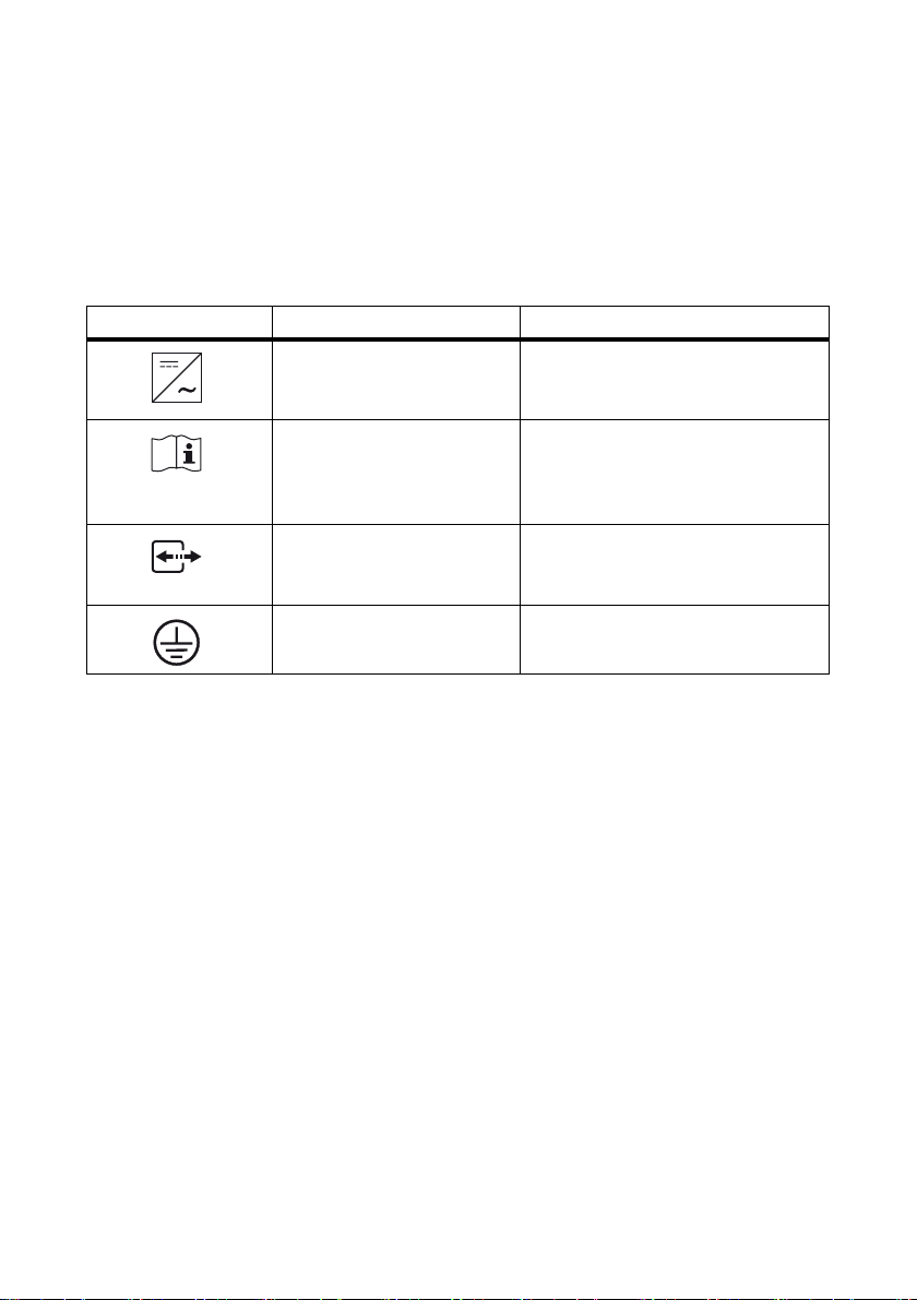
The following symbols are used as product markings with the following meanings.
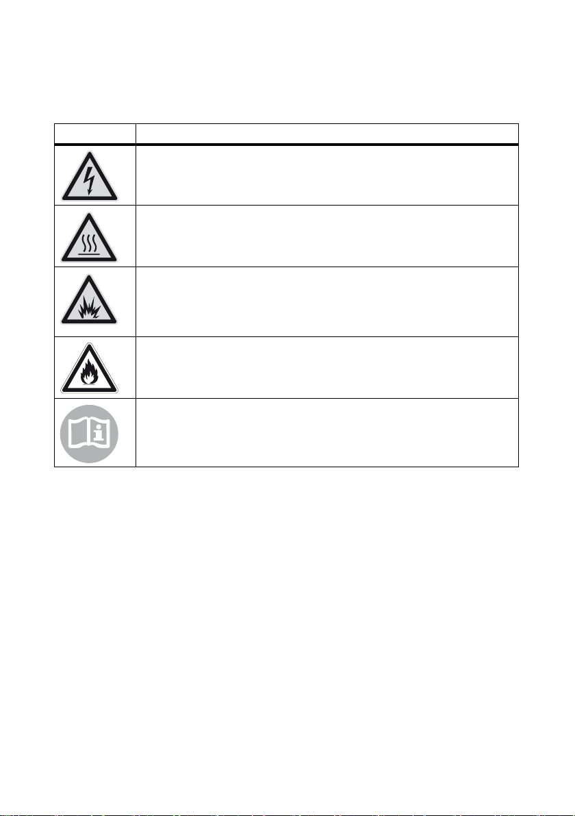
Symbol Description
Warning regarding dangerous voltage
The product works with high voltages. All work on the product must only be
performed as described in the documentation of the product.
Beware of hot surface
The product can become hot during operation. Do not touch the product during
operation.
Electric arc hazards
The product has large electrical potential differences between its conductors. Arc
flashes can occur through air when high-voltage current flows. Do not work on the
product during operation.
Risk of fire
Improper installation of the product may cause a fire.
Observe the operating instructions
Read the documentation of the product before working on it. Follow all safety
precautions and instructions as described in the documentation.
Installation Manual SB3-5TLUS22-IA-en-16 5
Page 6
General Warnings SMA America, LLC
General Warnings
General Warnings
Al l el ect ric al ins tal lat ions m ust be m ade in acc ord anc e wi th the local and NationalElectrical Code
ANSI/NFPA 70 or the Canadian Electrical Code® CSAC22.1. This document does not and is not
intended to replace any local, state, provincial, federal or national laws, regulation or codes
applicable to the installation and use of the product, including without limitation applicable
electrical safety codes. All installations must conform with the laws, regulations, codes and
standards applicable in the jurisdiction of installation. SMA assumes no responsibility for the
compliance or non-compliance with such laws or codes in connection with the installation of the
product.
The product contains no user-serviceable parts.
For all repair and maintenance, always return the unit to an authorized SMA Service Center.
Before installing or using the product, read all of the instructions, cautions, and warnings in this
manual.
Before connecting the product to the electrical utility grid, contact the local utility company. This
connection must be made only by qualified personnel.
Wiring of the product must be made by qualified personnel only.
®
6 SB3-5TLUS22-IA-en-16 Installation Manual
Page 7

SMA America, LLC Table of Contents
Table of Contents
1 Information on this Document. . . . . . . . . . . . . . . . . . . . . . . . . . 10
2 Safety . . . . . . . . . . . . . . . . . . . . . . . . . . . . . . . . . . . . . . . . . . . . . 12
2.1 Intended Use . . . . . . . . . . . . . . . . . . . . . . . . . . . . . . . . . . . . . . . . . . . 12
2.2 Skills of Qualified Persons . . . . . . . . . . . . . . . . . . . . . . . . . . . . . . . . . 12
2.3 Safety Precautions . . . . . . . . . . . . . . . . . . . . . . . . . . . . . . . . . . . . . . . 13
3 Scope of Delivery . . . . . . . . . . . . . . . . . . . . . . . . . . . . . . . . . . . . 14
4 Product Description . . . . . . . . . . . . . . . . . . . . . . . . . . . . . . . . . . 15
4.1 Sunny Boy . . . . . . . . . . . . . . . . . . . . . . . . . . . . . . . . . . . . . . . . . . . . . 15
4.2 DC Disconnect. . . . . . . . . . . . . . . . . . . . . . . . . . . . . . . . . . . . . . . . . . 17
4.3 Type Labels . . . . . . . . . . . . . . . . . . . . . . . . . . . . . . . . . . . . . . . . . . . . 18
4.3.1 Sunny Boy . . . . . . . . . . . . . . . . . . . . . . . . . . . . . . . . . . . . . . . . . . . . 18
4.3.2 DC Disconnect . . . . . . . . . . . . . . . . . . . . . . . . . . . . . . . . . . . . . . . . . 19
4.3.3 Symbols on the Type Labels. . . . . . . . . . . . . . . . . . . . . . . . . . . . . . . 20
4.4 Display. . . . . . . . . . . . . . . . . . . . . . . . . . . . . . . . . . . . . . . . . . . . . . . . 21
4.5 Communication Interface. . . . . . . . . . . . . . . . . . . . . . . . . . . . . . . . . . 23
4.6 Secure Power Supply (SPS). . . . . . . . . . . . . . . . . . . . . . . . . . . . . . . . 23
4.7 Fan Retrofit Kit . . . . . . . . . . . . . . . . . . . . . . . . . . . . . . . . . . . . . . . . . . 23
4.8 Arc-Fault Circuit Interrupter (AFCI). . . . . . . . . . . . . . . . . . . . . . . . . . . 24
4.9 SD Card Slot . . . . . . . . . . . . . . . . . . . . . . . . . . . . . . . . . . . . . . . . . . . 24
4.10 Varistors. . . . . . . . . . . . . . . . . . . . . . . . . . . . . . . . . . . . . . . . . . . . . . . 24
4.11 SMA OptiTrac Global Peak . . . . . . . . . . . . . . . . . . . . . . . . . . . . . . . 24
5 Mounting. . . . . . . . . . . . . . . . . . . . . . . . . . . . . . . . . . . . . . . . . . . 25
5.1 Selecting the Mounting Location . . . . . . . . . . . . . . . . . . . . . . . . . . . . 25
5.2 Mounting the Wall Mounting Bracket. . . . . . . . . . . . . . . . . . . . . . . . 28
5.3 Mounting the Inverter and DC Disconnect. . . . . . . . . . . . . . . . . . . . . 30
5.4 Attaching the Anti-Theft Device . . . . . . . . . . . . . . . . . . . . . . . . . . . . . 32
6 Electrical Connection . . . . . . . . . . . . . . . . . . . . . . . . . . . . . . . . . 33
6.1 Safety during Electrical Connection. . . . . . . . . . . . . . . . . . . . . . . . . . 33
Installation Manual SB3-5TLUS22-IA-en-16 7
Page 8

Table of Contents SMA America, LLC
6.2 Overview of the Connection Area. . . . . . . . . . . . . . . . . . . . . . . . . . . 34
6.2.1 Connection Area of the Inverter. . . . . . . . . . . . . . . . . . . . . . . . . . . . 34
6.2.2 Connection Area of the DC Disconnect. . . . . . . . . . . . . . . . . . . . . . 35
6.3 AC Connection . . . . . . . . . . . . . . . . . . . . . . . . . . . . . . . . . . . . . . . . . 36
6.3.1 Conditions for the AC Connection . . . . . . . . . . . . . . . . . . . . . . . . . . 36
6.3.2 Connecting the Inverter to the Utility Grid . . . . . . . . . . . . . . . . . . . . 37
6.4 DC Connection . . . . . . . . . . . . . . . . . . . . . . . . . . . . . . . . . . . . . . . . . 39
6.4.1 Safety during DC Connection . . . . . . . . . . . . . . . . . . . . . . . . . . . . . 39
6.4.2 Conditions for the DC Connection . . . . . . . . . . . . . . . . . . . . . . . . . . 39
6.4.3 Connecting the PV Array . . . . . . . . . . . . . . . . . . . . . . . . . . . . . . . . . 41
6.5 Connecting the Secure Power Supply Module . . . . . . . . . . . . . . . . . 44
7 Commissioning . . . . . . . . . . . . . . . . . . . . . . . . . . . . . . . . . . . . . . 47
7.1 Making Settings via the Rotary Switches. . . . . . . . . . . . . . . . . . . . . . 47
7.1.1 Overview of the Rotary Switches . . . . . . . . . . . . . . . . . . . . . . . . . . . 47
7.1.2 Changing the Country Data Set and the Display Language . . . . . . 49
7.1.3 Changing the Display Language . . . . . . . . . . . . . . . . . . . . . . . . . . . 50
7.2 Commissioning the Inverter . . . . . . . . . . . . . . . . . . . . . . . . . . . . . . . . 51
8 Configuration . . . . . . . . . . . . . . . . . . . . . . . . . . . . . . . . . . . . . . . 52
8.1 Changing the Country Data Set Using a Communication Product . . 52
8.2 Activating and Setting SMA OptiTrac Global Peak . . . . . . . . . . . . . 52
9 Display and LEDs . . . . . . . . . . . . . . . . . . . . . . . . . . . . . . . . . . . . 53
9.1 Switching On the Display . . . . . . . . . . . . . . . . . . . . . . . . . . . . . . . . . 53
9.2 Calling Up Messages of the Start Phase . . . . . . . . . . . . . . . . . . . . . . 53
9.3 LED Signals . . . . . . . . . . . . . . . . . . . . . . . . . . . . . . . . . . . . . . . . . . . . 54
10 Disconnecting the Inverter from Voltage Sources . . . . . . . . . . 55
10.1 Disconnecting the DC Disconnect from Voltage Sources. . . . . . . . . . 57
11 Troubleshooting . . . . . . . . . . . . . . . . . . . . . . . . . . . . . . . . . . . . . 59
11.1 Event Messages. . . . . . . . . . . . . . . . . . . . . . . . . . . . . . . . . . . . . . . . . 59
11.2 Error Messages . . . . . . . . . . . . . . . . . . . . . . . . . . . . . . . . . . . . . . . . . 60
11.3 Cleaning the Inverter . . . . . . . . . . . . . . . . . . . . . . . . . . . . . . . . . . . . . 71
8 SB3-5TLUS22-IA-en-16 Installation Manual
Page 9

SMA America, LLC Table of Contents
11.4 Cleaning the Fan . . . . . . . . . . . . . . . . . . . . . . . . . . . . . . . . . . . . . . . . 71
11.4.1 Sunny Boy 3000/3800/4000/5000/6000TL-US . . . . . . . . . . . . 71
11.4.2 Sunny Boy 7000/7700TL-US . . . . . . . . . . . . . . . . . . . . . . . . . . . . . 73
11.5 Checking the PV System for Ground Faults . . . . . . . . . . . . . . . . . . . . 74
11.6 Replacing DC Varistors . . . . . . . . . . . . . . . . . . . . . . . . . . . . . . . . . . . 76
11.7 The Message "Electr. arc detected" is displayed. . . . . . . . . . . . . . . . 78
12 Decommissioning . . . . . . . . . . . . . . . . . . . . . . . . . . . . . . . . . . . . 80
12.1 Disassembling the Inverter . . . . . . . . . . . . . . . . . . . . . . . . . . . . . . . . . 80
12.2 Packing the Inverter . . . . . . . . . . . . . . . . . . . . . . . . . . . . . . . . . . . . . . 81
12.3 Disposing of the Inverter . . . . . . . . . . . . . . . . . . . . . . . . . . . . . . . . . . 81
13 Technical Data . . . . . . . . . . . . . . . . . . . . . . . . . . . . . . . . . . . . . . 82
13.1 DC/AC . . . . . . . . . . . . . . . . . . . . . . . . . . . . . . . . . . . . . . . . . . . . . . . 82
13.1.1 Sunny Boy 3000TL-US. . . . . . . . . . . . . . . . . . . . . . . . . . . . . . . . . . . 82
13.1.2 Sunny Boy 3800TL-US . . . . . . . . . . . . . . . . . . . . . . . . . . . . . . . . . . . 83
13.1.3 Sunny Boy 4000TL-US. . . . . . . . . . . . . . . . . . . . . . . . . . . . . . . . . . . 84
13.1.4 Sunny Boy 5000TL-US. . . . . . . . . . . . . . . . . . . . . . . . . . . . . . . . . . . 85
13.1.5 Sunny Boy 6000TL-US. . . . . . . . . . . . . . . . . . . . . . . . . . . . . . . . . . . 86
13.1.6 Sunny Boy 7000TL-US . . . . . . . . . . . . . . . . . . . . . . . . . . . . . . . . . . . 87
13.1.7 Sunny Boy 7700TL-US . . . . . . . . . . . . . . . . . . . . . . . . . . . . . . . . . . . 88
13.2 Protective Devices . . . . . . . . . . . . . . . . . . . . . . . . . . . . . . . . . . . . . . . 89
13.3 General Data. . . . . . . . . . . . . . . . . . . . . . . . . . . . . . . . . . . . . . . . . . . 90
13.4 DC Disconnect. . . . . . . . . . . . . . . . . . . . . . . . . . . . . . . . . . . . . . . . . . 91
13.5 Climatic Conditions . . . . . . . . . . . . . . . . . . . . . . . . . . . . . . . . . . . . . . 91
13.6 Features . . . . . . . . . . . . . . . . . . . . . . . . . . . . . . . . . . . . . . . . . . . . . . . 91
13.7 Torques . . . . . . . . . . . . . . . . . . . . . . . . . . . . . . . . . . . . . . . . . . . . . . . 92
13.8 Data Storage Capacity . . . . . . . . . . . . . . . . . . . . . . . . . . . . . . . . . . . 92
14 Accessories . . . . . . . . . . . . . . . . . . . . . . . . . . . . . . . . . . . . . . . . . 93
15 Compliance Information . . . . . . . . . . . . . . . . . . . . . . . . . . . . . . 94
16 Contact . . . . . . . . . . . . . . . . . . . . . . . . . . . . . . . . . . . . . . . . . . . . 95
Installation Manual SB3-5TLUS22-IA-en-16 9
Page 10
1 Information on this Document SMA America, LLC
1 Information on this Document
Validity
This document is valid for the following device types as of firmware version HP V02.05.00.R,
KP V02.50.55.R:
• Sunny Boy 3000TL-US (SB 3000TL-US-22)
• Sunny Boy 3800TL-US (SB 3800TL-US-22)
• Sunny Boy 4000TL-US (SB 4000TL-US-22)
• Sunny Boy 5000TL-US (SB 5000TL-US-22)
• Sunny Boy 6000TL-US (SB 6000TL-US-22)
• Sunny Boy 7000TL-US (SB 7000TL-US-22)
• Sunny Boy 7700TL-US (SB 7700TL-US-22)
Target Group
Th is d ocu men t is fo r qu ali fie d pe rso ns. On ly p ers ons with t he a ppropriate skills are allowed to perform
the tasks described in this document (see Section2.2 "Skills of Qualified Persons", page12).
Additional Information
Links to additional information can be found at www.SMA-Solar.com.
Document title Document type
Capacitive Leakage Currents Technical information
Shade Management Technical information
Module Technology Technical information
Symbols
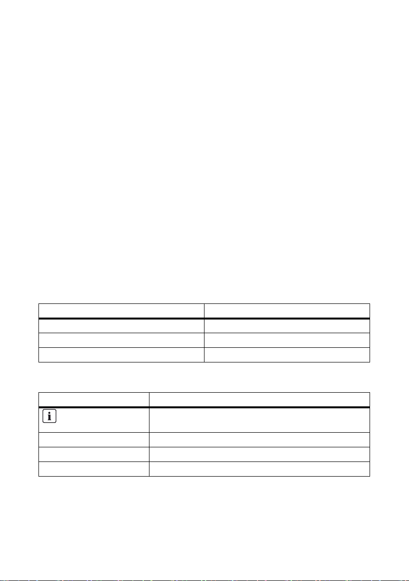
Symbol Explanation
Indicates information that is important for a specific topic or
objective, but is not safety-relevant.
☐ Indicates a requirement for meeting a specific goal.
☑ Desired result
✖ A problem that could occur
10 SB3-5TLUS22-IA-en-16 Installation Manual
Page 11

SMA America, LLC 1 Information on this Document
Nomenclature
Complete designation Designation in this document
SMA America Production, LLC SMA
SMA Solar Technology Canada Inc. SMA
Sunny Boy Inverter, product
Installation Manual SB3-5TLUS22-IA-en-16 11
Page 12

2 Safety SMA America, LLC
2 Safety
2.1 Intended Use
The Sunny Boy is a transformerless PV inverter which converts the direct current of a PV array into
grid-compliant alternating current and feeds it into the utility grid.
The inverter can be installed in the following grid configurations:
• 208Y/120 VAC Wye
• 120/240 VAC Split phase
The inverter is transformerless and has no galvanic isolation. Therefore, the inverter may only be
operated with ungrounded PV arrays. Furthermore, the PV array must be installed in accordance with
the National Electrical Code
locally valid regulations for ungrounded PV arrays. Additionally, the PV array (PV modules and
cabling) must have protective insulation and the PV modules used must be suitable for use with this
inverter. PV modules with a high capacity to ground may only be used if their coupling capacity does
not exceed 1,400 nF (for information on how to calculate the coupling capacity, see Technical
Information "Capacitive Leakage Currents" at www.SMA-Solar.com).
All components must remain within their permitted operating ranges at all times.
The inverter is suitable for indoor and outdoor use.
• Do not mount the inverter on flammable construction materials.
• Do not mount the inverter in areas where highly flammable materials are stored.
• Do not mount the inverter in areas having a potentially explosive atmosphere.
Only use this product in accordance with the enclosed documentation and with the local standards
and directives. Any other use may cause injury to persons or property damage. For safety reasons,
it is forbidden to modify the product or install components that are not explicitly recommended for this
product or distributed by SMA.
The enclosed documentation is an integral part of this product.
• Read and adhere to the documentation.
• Keep the documentation in a convenient place for future reference.
®
, Article 690.35 "Ungrounded Photovoltaic Power Systems" and the
2.2 Skills of Qualified Persons
The tasks described in this document may only be performed by qualified persons. The qualified
person must have the following skills:
• Knowledge of how an inverter works and is operated
• Training in how to deal with the dangers and risks associated with installing and using electrical
devices and plants
• Training in the installation and commissioning of electrical devices and plants
• Knowledge of all applicable standards and directives
• Knowledge of and adherence to this document and all safety precautions
12 SB3-5TLUS22-IA-en-16 Installation Manual
Page 13

SMA America, LLC 2 Safety
2.3 Safety Precautions
Danger to life from electric shock due to high voltages in the inverter
High voltages that can cause fatal electric shocks are present in the live components of the inverter.
• All work on the inverter may only be carried out by qualified persons.
• Prior to performing any work on the inverter, disconnect the inverter on the AC and DC sides
(see Section10 "Disconnecting the Inverter from Voltage Sources", page55).
• Only operate the inverter with the enclosure lid closed.
• Do not open the upper enclosure lid.
Danger to life from electric shock due to damaged devices
Operating a damaged inverter can lead to hazardous situations that result in death or serious
injuries due to electric shock.
• Only operate the inverter if it is technically safe and in full working order.
• Check the inverter regularly for visible damage.
• Only operate the inverter if there is no visible damage.
Risk of burns due to hot surfaces
The surface of the inverter can become very hot. Touching the surface can result in burns.
• Do not touch hot surfaces.
• During operation, do not touch any parts other than the lower enclosure lid of the inverter.
• Observe the safety messages on the inverter.
Damage to the inverter due to electrostatic discharge
Touching electronic components can cause damage to or destroy the inverter through electrostatic
discharge.
• Ground yourself before touching any components.
Observe local regulations
All electrical installations must comply with the electrical standards applicable on-site and the
National Electrical Code® (ANSI/NFPA 70). Installations in Canada must comply with the
applicable Canadian standards.
Installation Manual SB3-5TLUS22-IA-en-16 13
Page 14
3 Scope of Delivery SMA America, LLC
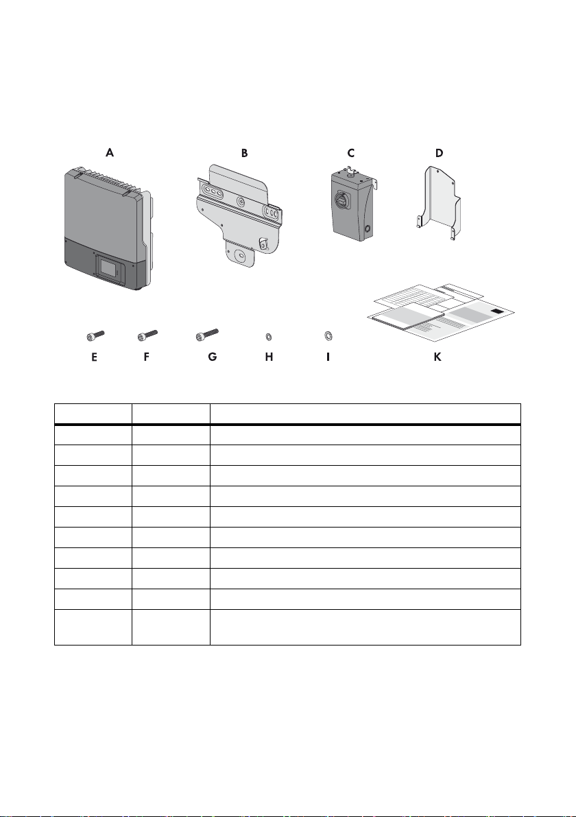
3 Scope of Delivery
Check the scope of delivery for completeness and any externally visible damage.
Contact your distributor if the scope of delivery is incomplete or damaged.
Figure1: Components included in the scope of delivery
Item Quantity Description
A1Inverter
B 1 Wall mounting bracket for the inverter
C1DC Disconnect
D 1 Wall mounting bracket for the DC Disconnect
E 3 M5 x 8 cheese-head screw
F 2 M5 x 12 cheese-head screw
G 1 M6 x 16 cheese-head screw
H 6 M5 conical spring washer (including 1 spare)
I1M6 conical spring washer
K 1 Installation manual, user manual, production test report,
supplementary sheet with the default settings
14 SB3-5TLUS22-IA-en-16 Installation Manual
Page 15
SMA America, LLC 4 Product Description
4 Product Description
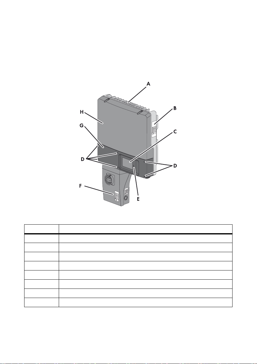
4.1 Sunny Boy
The Sunny Boy is a transformerless PV inverter which converts the direct current of a PV array into
grid-compliant alternating current and feeds it into the utility grid.
Figure2: Sunny Boy design
Item Description
A Cooling fins
B Type label
CDisplay
D Lower enclosure lid screws
ELEDs
FDC Disconnect
GLower enclosure lid
H Upper enclosure lid
Installation Manual SB3-5TLUS22-IA-en-16 15
Page 16
4 Product Description SMA America, LLC
The Sunny Boy is a multi-string inverter that has two input areas, A and B, each with its own
MPP tracker. This continually determines the maximum power point and controls the voltage on the
PV modules accordingly. The two separate MPP trackers make it possible to connect different
PV strings to input areas A and B. The PV strings may vary in the number of PV modules, their
orientation to the sun and shading.
Symbols on the Inverter
Symbol Description Explanation
Inverter This symbol defines the function of the
green LED. The green LED indicates the
operating state of the inverter.
Observe the documentation. This symbol defines the function of the
red LED. The red LED indicates an error.
Read this document for instructions on
how to correct the error.
Communication This symbol defines the function of the
blue LED. The blue LED indicates the
communication state of the inverter.
Equipment grounding
conductor terminal
Connection for the AC equipment
grounding conductor
16 SB3-5TLUS22-IA-en-16 Installation Manual
Page 17
SMA America, LLC 4 Product Description
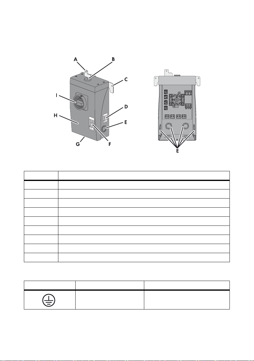
4.2 DC Disconnect
The DC Disconnect is a DC load-break switch which safely disconnects the PV array from the inverter.
Figure3: DC Disconnect design
Item Description
A Bracket for grounding the DC Disconnect enclosure
B Rubber grommet for the enclosure opening
C Bracket for hanging in the retainer
D Type label 1
EConduit knockouts
F Type label 2
G Enclosure lid screws
HEnclosure lid
ISwitch
Symbols on the DC Disconnect
Symbol Description Explanation
Equipment grounding
conductor terminal
Installation Manual SB3-5TLUS22-IA-en-16 17
Connection for the DC equipment
grounding conductors
Page 18

4 Product Description SMA America, LLC
4.3 Type Labels
4.3.1 Sunny Boy
The type label provides a unique identification of the inverter. The type label is located on the
right-hand side of the enclosure.
Figure4: Type label design
Item Description Explanation
A Model Inverter device type
B S/N Inverter serial number
C Date of manufacture Inverter manufacture date (month/year)
D Device-specific characteristics ‒
The information on the type label is required for both safe operation of the inverter and for customer
support from the SMA Service Line. The type label must remain permanently affixed to the inverter.
18 SB3-5TLUS22-IA-en-16 Installation Manual
Page 19
SMA America, LLC 4 Product Description
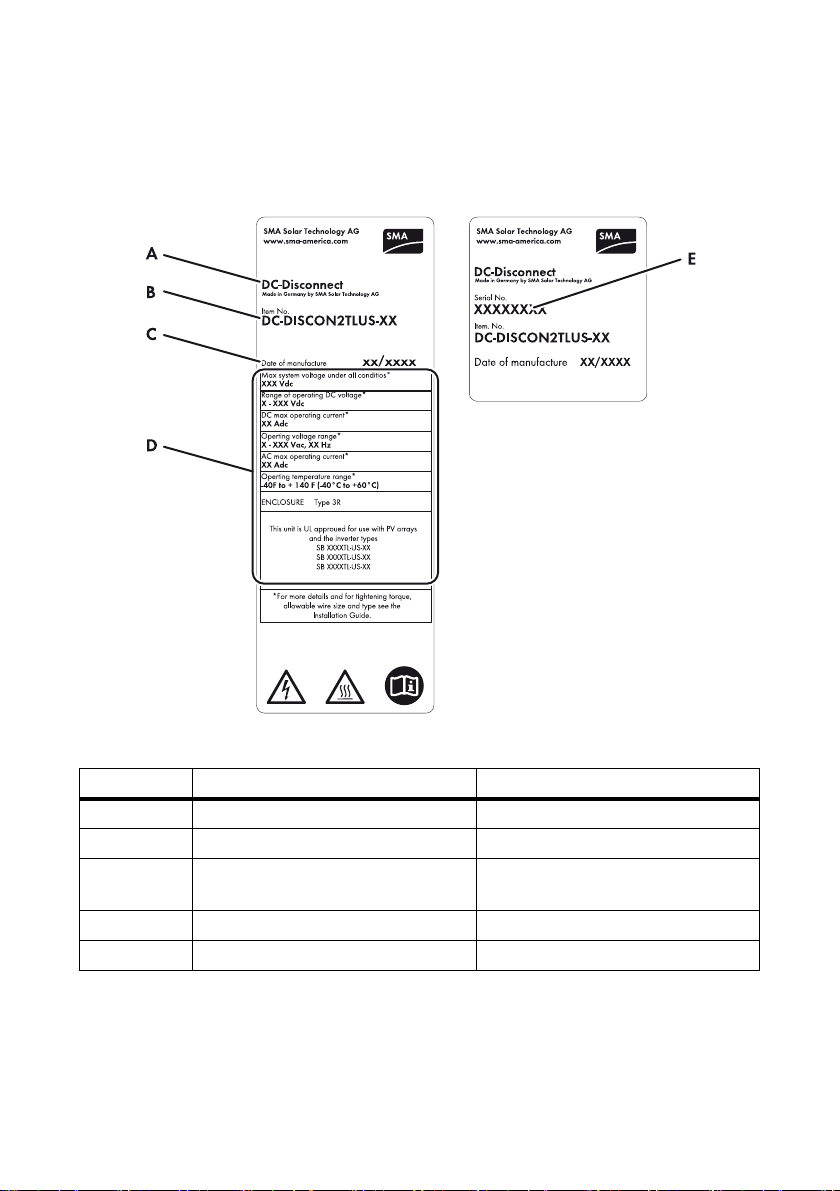
4.3.2 DC Disconnect
The type label provides a unique identification of the DC Disconnect. The type label is located on the
right-hand side of the enclosure.
Figure5: Layout of the type label
Item Description Explanation
A‒ Product name
B Item No. DC Disconnect device type
CDate of manufacture DC Disconnect manufacture date
(month/year) of the
D Device-specific characteristics ‒
E Serial No. DC Disconnect serial number
You will require the information on the type label to use the DC Disconnect safely and when seeking
customer support from the SMA Service Line. The type label must remain permanently affixed to the
DC Disconnect.
Installation Manual SB3-5TLUS22-IA-en-16 19
Page 20
4 Product Description SMA America, LLC
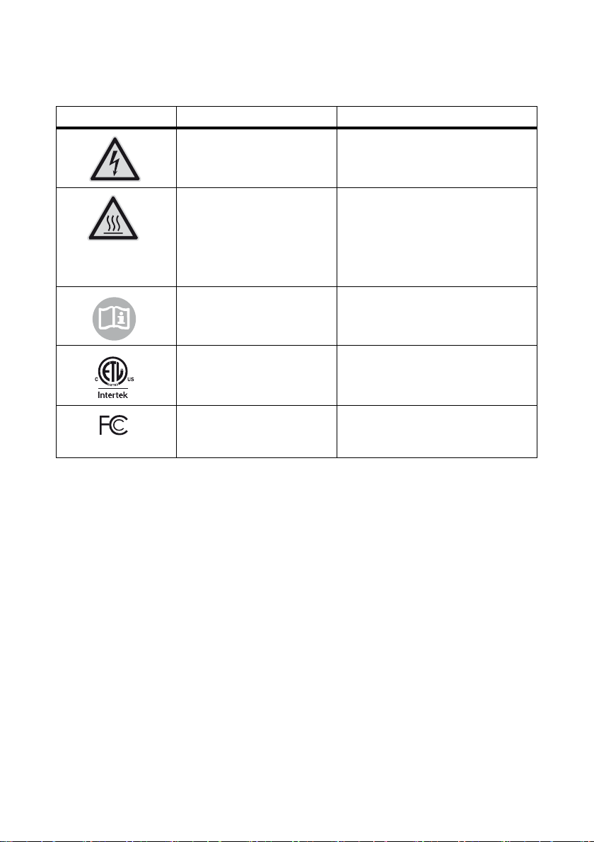
4.3.3 Symbols on the Type Labels
Symbol Description Explanation
Danger to life due to high
voltages
Risk of burns due to hot surfaces The product can become hot during
Observe the documentation. Observe all documentation that is
ETL test mark The product has been certified by
FCC test mark The product complies with the
The product operates at high voltages.
All work on the inverter may only be
carried out by qualified persons.
operation. Avoid contact during
operation. Allow the product to cool
down sufficiently before carrying out
any work. Wear personal protective
equipment such as safety gloves.
supplied with the product.
Intertek as being in accordance with the
applicable directives.
requirements of the applicable
FCC standards.
20 SB3-5TLUS22-IA-en-16 Installation Manual
Page 21

SMA America, LLC 4 Product Description
4.4 Display
The display shows the current operating data of the inverter (e.g. current power, daily energy,
total energy) as well as events or error messages. The power and energy are displayed as bars in the
diagram.
Figure6: Display layout (example)
Position Description Explanation
A Power Current power
B Day Daily energy
C Tot al To tal en ergy g enera ted si nce th e initia l star t-u p of
the inverter
D Active functions Displays the activated or active functions for
communication, network system services or
temperature derating
E Line conductor Line conductor involved for the values displayed
F Event number relating to the
Event number of errors relating to the utility grid
utility grid
G Output voltage/output current Displays output voltage and output current of a
line conductor in alternation
H Event number relating to the
Event number of errors relating to the inverter
inverter
I Input voltage/input current Displays input voltage and input current of an
input in alternation
Installation Manual SB3-5TLUS22-IA-en-16 21
Page 22
4 Product Description SMA America, LLC
Position Description Explanation
K Event number relating to the
Event number of errors relating to the PV array
PV array
L Text line Displays an event message or error message
M Power and yield curve Displays the power curve of the last 16 feed-in
hours or the energy yields of the last 16 days
• In order to switch between the displays,
tap once on the enclosure lid.
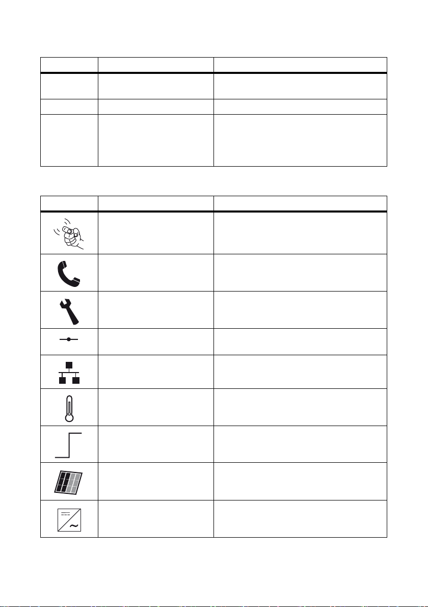
Symbols on the Display
Symbol Description Explanation
Tapping You can operate the display by tapping it
(see Section9 "Display and LEDs", page53).
Telephone receiver Indicates a fault that cannot be corrected on site
• Contact the SMA Service Line
Wrench Indicates a fault that can be corrected on site by
a qualified person
Speedwire connection Indicates that communication via Speedwire is
active and that there is a network connection
Webconnect function Indicates that there is a connection to
Sunny Portal
Temperature symbol Indicates that the power of the inverter is limited
due to excessive temperature
Power limitation Indicates that external active power limitation via
the Power Reducer Box is active
PV array ‒
Inverter ‒
22 SB3-5TLUS22-IA-en-16 Installation Manual
Page 23
SMA America, LLC 4 Product Description
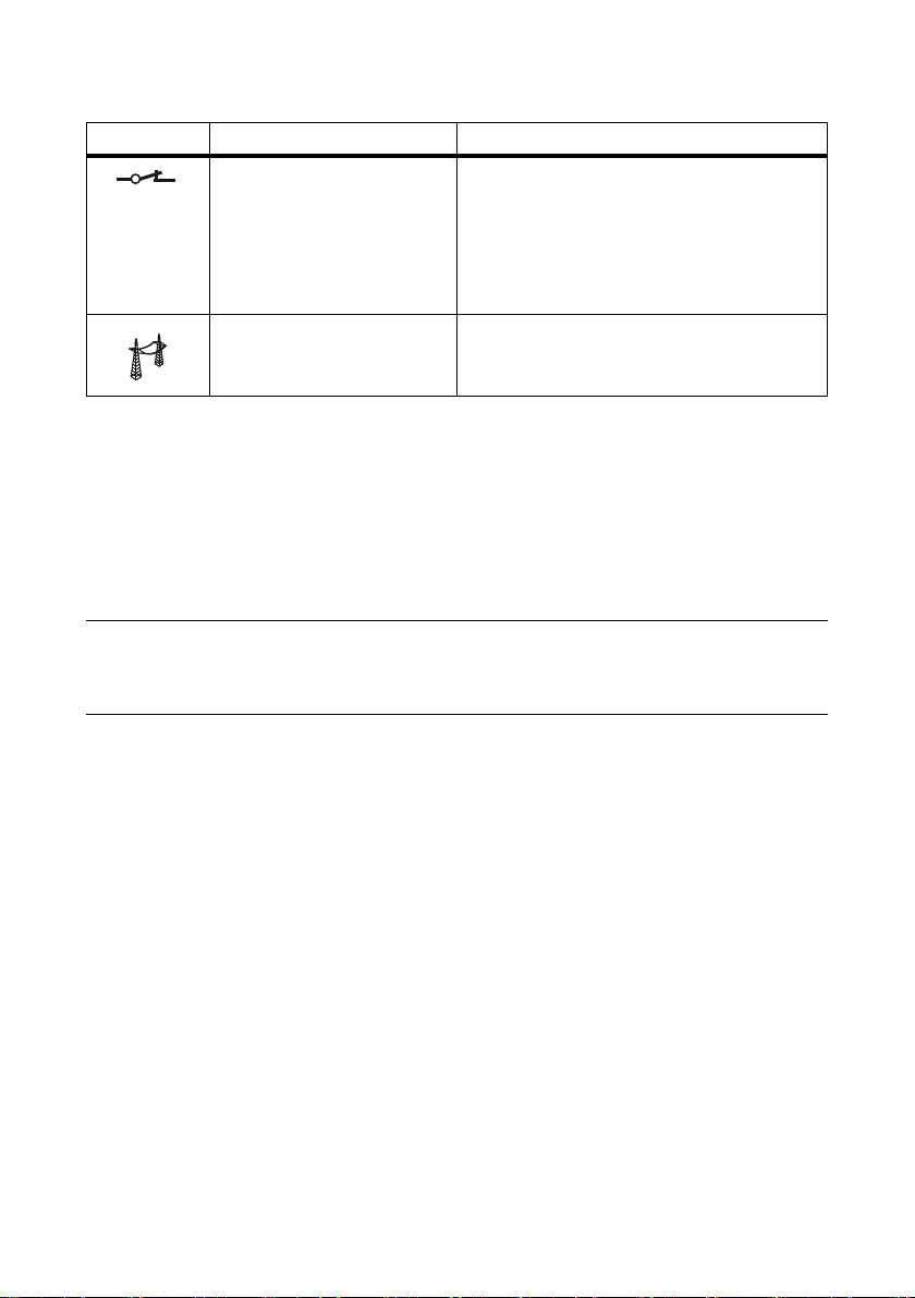
Symbol Description Explanation
Grid relay Grid relay closed:
indicates that the inverter is feeding into the
utility grid
Grid relay open:
indicates that the inverter is disconnected from
the utility grid
Utility grid ‒
4.5 Communication Interface
The inverter can be fitted with a communication interface (e.g. RS485 or Speedwire with Webconnect
function). This communication interface enables the inverter to co mmun ica te wi th SMA c ommu nic atio n
products or other inverters (for information on supported products, see www.SMA-Solar.com).
You can only set the inverter parameters via SMA communication products.
Depending on the type of communication, RS485 or Speedwire, the parameters and messages are
displayed differently on the communication products.
Example: How the country data set parameter is displayed
For communication with RS485: CntrySet parameter
For communication with Speedwire: Set country standard parameter
You can adjust the country data set of the inverter before commissioning or within the first ten
operating hours via the two rotary switches in the inverter. All other operating parameters can only
be set via communication products.
4.6 Secure Power Supply (SPS)
The inv erter has an SPS mo dule that can supply th e PV array energy to an additional outlet connected
to the inverter in the event of grid failures of longer durations. The SPS module also has a connection
for the fan retrofit kit, enabling an external fan to be controlled.
4.7 Fan Retrofit Kit
The fan retrofit kit is used for additional inverter cooling at high ambient temperatures (for information
on installation and configuration, see the fan retrofit kit installation manual). The fan retrofit kit can be
retrofitted, installed at the factory if specified in the order, or included in the regular scope of delivery.
The Sunny Boy 6000TL-US, 7000TL-US and 7700TL-US are equipped with a fan as standard.
Installation Manual SB3-5TLUS22-IA-en-16 23
Page 24

4 Product Description SMA America, LLC
4.8 Arc-Fault Circuit Interrupter (AFCI)
In accordance with the National Electrical Code®, Article 690.11, the inverter has a system for the
recognition of electric arc detection and interruption. An electric arc with a power of 300 W or
greater must be interrupted by the AFCI within the time specified by UL 1699B. A tripped AFCI can
only be reset manually. You can deactivate the automatic arc fault detection and interruption (AFCI)
via a communication product in "Installer" mode if you do not require this function. The 2011 edition
of the National Electrical Code
to a building must be fitted with a means of detecting and disconnecting serial electric arcs (AFCI) on
the PV side.
®
, Section 690.11 stipulates that newly installed PV systems attached
4.9 SD Card Slot
The inverter is equipped with an SD card slot. You can use the SD card when required to update the
inverter firmware.
4.10 Varistors
The DC Disconnect is equipped with four varistors on the DC side. Varistors are voltage-dependent
re sis tor s that pro tec t th e inve rte r on th e DC sid e agai nst sur ge overvoltages. It may be necessary under
certain circumstances to replace the varistors (see Section11.6 "Replacing DC Varistors", page76).
Despite this protection against surge overvoltages, PV arrays must be designed in such a way that the
maximum system voltage of the inverter is not exceeded (see Section13 "Technical Data", page82).
4.11 SMA OptiTrac Global Peak
SMA OptiTrac Global Peak is a further development of the MPP tracking tool SMA OptiTrac. MPP
tracking is a process that determines the highest usable power in the PV system at any given time.
The power generated by the PV array depends on the level of solar irradiation and the temperature
of the PV modules. As a result, the optimum operating point for maximum power (MPP) changes
constantly throughout the day.
SMA OptiTrac ensures that the operating point of the inverter always follows the MPP exactly.
In addition, with the aid of SMA OptiTrac Global Peak the inverter can detect the presence of several
maximum power points within the available operating range, such as may occur with partially shaded
strings in particular. The available power of the partially shaded strings can therefore be almost
completely fed into the utility grid.
SMA OptiTrac Global Peak is deactivated as standard and should, in the event of partially shaded
PV modules, be activated and set via a communication product (see Section 8.7).
24 SB3-5TLUS22-IA-en-16 Installation Manual
Page 25

SMA America, LLC 5 Mounting
5 Mounting
5.1 Selecting the Mounting Location
Requirements for the mounting location:
Danger to life due to fire or explosion
Despite careful construction, electrical devices can cause fires.
• Do not mount the inverter in areas where highly flammable materials are stored.
• Do not mount the inverter in areas having a potentially explosive atmosphere
The inverter can become hot during operation
Touching the enclosure can result in burn injuries.
• Install the inverter in such a way that it cannot be touched accidentally.
☐ The inverter must be mounted to a solid building ground (e.g., concrete or block wall) or on
drywall to a beam or stud.
☐ In living areas, make sure that the building ground is not made of plasterboard or similar.
When in operation, the inverter makes noises which can be perceived as a nuisance.
☐ The mounting location must be suitable for the weight and dimensions of the inverter with
DC Disconnect (see Section13 "Technical Data", page82).
☐ The mounting location must not be exposed to direct sources of water spray such as sprinklers
or gutters.
☐ Climatic conditions must be met (see Section13 "Technical Data", page82).
☐ The mounting location should be freely and safely accessible at all times without the necessity
for any auxiliary equipment, such as scaffolding or lifting platforms. Non-fulfillment of these
criteria may restrict servicing.
☐ The mounting location should not be exposed to direct solar irradiation. Direct solar irradiation
ca n in cre ase the ope rat ing tem per atu re o f th e in ver ter . As a result, the inverter reduces its power
output in order to remain within the operating limits.
☐ To ensure optimal operation, the ambient temperature must be below 104°F (40°C).
The inverter can, however, be operated at higher ambient temperatures without risk in the event
of any possible reductions in output power.
Installation Manual SB3-5TLUS22-IA-en-16 25
Page 26
5 Mounting SMA America, LLC
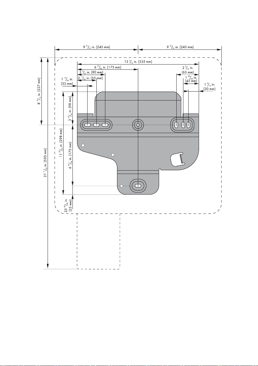
Dimensions for mounting:
Figure7: Wall mounting bracket dimensions
26 SB3-5TLUS22-IA-en-16 Installation Manual
Page 27

SMA America, LLC 5 Mounting
Recommended Clearances
Figure8: Recommended clearances
• To ensure optimal operation, maintain recommended clearances to walls, other inverters or
objects. This will prevent the inverter from reducing its power due to high temperatures.
• If the inverter is mounted outdoors, the clearance between the DC D isc onn ect and the fl oor mus t
be 3 ft. (914 mm). This prevents the ingress of splashing water into the DC Disconnect.
• Do not place or hang any objects on the inverter.
Installation Manual SB3-5TLUS22-IA-en-16 27
Page 28
5 Mounting SMA America, LLC
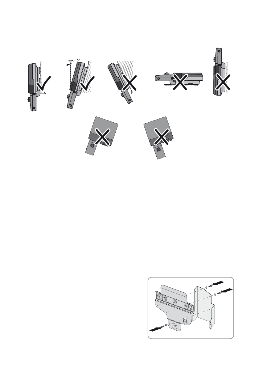
Observe the permitted mounting position:
Figure9: Permitted and prohibited mounting positions
• Mount the inverter in a permitted mounting position with the display at eye level. This ensures
th at t her e can b e no in gre ss o f mo istur e in to t he inv ert er a nd that you can read display messages
and LED signals without any difficulty.
5.2 Mounting the Wall Mounting Bracket
Additionally required mounting material (not included in the scope of delivery):
☐ 2 or 3 screws (minimum diameter
☐2 or 3 washers (minimum external diameter 3⁄4 in. (18 mm)) that are suitable for the screws
☐ 2 or 3 screw anchors that are suitable for the foundation. Do not use hollow-wall anchors or
toggle bolts for mounting on drywall.
☐ If the inverter is to be protected against theft, 1 padlock (see Section5.4 "Attaching the
Anti-Theft Device", page32)
1. Attach the DC Disconnect bracket to the wall
mounting bracket of the inverter using the screws
and conical spring washers included in the delivery
and tighten them with an Allen key (AF 4) (torque:
44 in.-lbs (5.0 Nm)). Tighten the two upper screws
(M5x12) from the rear and the lower (M5x8) from
the front.
28 SB3-5TLUS22-IA-en-16 Installation Manual
1
⁄4 in. (6 mm)) that are suitable for the foundation
Page 29
SMA America, LLC 5 Mounting
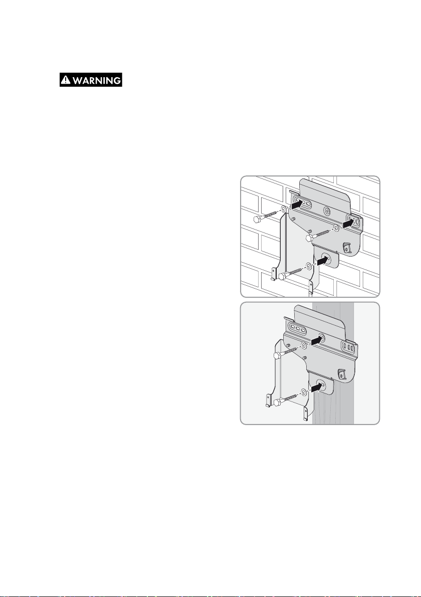
2. Align the wall mounting bracket horizontally at the mounting location.
3.
Danger to life due to electric shock or explosion if you drill into supply lines
Th ere may be gas pip es or e lec tri c cabl es b ehi nd the mount ing points which could be damaged
when drilling the holes for the wall mounting bracket.
• Make sure that there are no supply lines behind the mounting points.
4. Mark the p osition of the drill holes usi ng the wall mounting bracket and screw the wall mounting
bracket onto the wall using the screws and washers.
• For mounting on a stone wall, use one hole on
the right-hand and left-hand side and the lower
hole in the wall mounting bracket.
• For mounting on a stud or post in a drywall
construction, use the two holes at the center.
Installation Manual SB3-5TLUS22-IA-en-16 29
Page 30

5 Mounting SMA America, LLC
5.3 Mounting the Inverter and DC Disconnect
1.
Risk of injury when lifting the inverter, or if it is dropped
The inverter is heavy (see Section13 "Technical Data", page82). Risk of injury exists due to
incorrect lifting and due to the inverter falling during transport or when hanging in the wall
mounting bracket.
• Lift and transport the inverter horizontally in the mounting position. Use the recessed grips
on the sides for this.
2. Hang the inverter in the wall mounting bracket.
3. Ensure that the inverter is securely in place.
4. Remove the lower lid.
5. Carefully pierce the rubber grommet on the upper side of the DC Disconnect using a
screwdriver.
30 SB3-5TLUS22-IA-en-16 Installation Manual
Page 31

SMA America, LLC 5 Mounting
6. Place the DC Disconnect into the retainer from the
front.
7. Attach t he D C Di sco nne ct t o th e gr oun d co nne ction
on the inverter using the grounding bracket. Use the
M6x8 screw included in the delivery, the
corresponding conical spring washer and an Allen
key (AF 5) (torque: 53 in-lbs. (6 Nm)). When doing
so, ensure that the holes in the lateral brackets of
the DC Disconnect are flush with the holes in the
retainer.
8. Attach the DC Disconnect to the bracket using the
M5x8 screws and conical spring washers included
in the delivery and an Allen key (AF 4) (torque:
44in-lbs. (5 Nm)).
9. Feed the inverter DC cable through the rubber
grommet on the upper side of the DC Disconnect.
Installation Manual SB3-5TLUS22-IA-en-16 31
Page 32

5 Mounting SMA America, LLC
5.4 Attaching the Anti-Theft Device
You can protect the inverter from theft by installing a padlock. The padlock secures the inverter to the
wall mounting bracket.
The padlock must meet the following requirements:
☐ The material should be rust-proof.
☐ The lock shackle should be hardened.
☐ The lock cylinder should be secured.
☐ If mounted outdoors, the padlock should be weather-proof.
Figure10: Dimensions of the padlock as anti-theft device
Item Dimensions
A 6 mm (0.23 in.)
B 21 mm to 33 mm (0.83 in. to 1.30 in.)
C 20 mm to 33 mm (0.79 in. to 1.30 in.)
D 40 mm to 60 mm (1.57 in. to 2.36 in.)
E 13 mm to 21 mm (0.51 in. to 0.83 in.)
1. Place the shackle of the padlock through the metal
bracket on the wall mounting bracket and through
the bracket on the rear of the inverter. Whilst doing
so , mo ve t he s hac kle out war d fr om t he c ent er o f th e
inverter.
2. Close the shackle.
32 SB3-5TLUS22-IA-en-16 Installation Manual
Page 33

SMA America, LLC 6 Electrical Connection
6 Electrical Connection
6.1 Safety during Electrical Connection
Danger to life from electric shock due to high voltages
Hi gh v olt age s are p res ent in t he D C cabl es a nd l ater d uri ng o peration in the conductive components
of the inverter. These can cause fatal electric shocks.
• Before working on the inverter, always disconnect the inverter from all voltage sources as
described in Section 10.
• Do not open the upper enclosure lid.
Damage to the seal of the enclosure lid during sub-zero conditions
When opening the enclosure lid during sub-zero conditions, the seal of the enclosure lid can be
damaged. There may be an ingress of moisture, which can damage the inverter.
• Do not open the inverter when the outside temperature is below 23°F ( − 5°C).
Damage to the inverter due to electrostatic discharge
Touching electronic components can cause damage to or destroy the inverter through electrostatic
discharge.
• Ground yourself before touching any components.
Damage to the inverter due to moisture ingress
Electronic components in the inverter can be destroyed or damaged as a result of the ingress of
moisture.
• Only use listed conduit fittings for inserting the conduits into the inverter and the
DC Disconnect.
• For outdoor installations, only use rain-tight conduit fittings or conduit fittings for wet locations.
Damage to or failure of the inverter due to incorrectly connected cables
Insecure or high-resistance cable connections (such as incorrectly installed twist-on connectors) can
cause ground faults or arc faults that can lead to the damage or failure of the inverter.
• Select and correctly install cable connections that ensure secure, low-resistance connections
for all electrical connections in the PV system.
Observe local regulations
All electrical installations must comply with the electrical standards applicable on-site and the
National Electrical Code® (ANSI/NFPA 70). Installations in Canada must comply with the
applicable Canadian standards.
Installation Manual SB3-5TLUS22-IA-en-16 33
Page 34

6 Electrical Connection SMA America, LLC
6.2 Overview of the Connection Area
6.2.1 Connection Area of the Inverter
Figure11: Connection area inside the inverter
Item Description Explanation
A DC cable For the connection of the inverter and
DC Disconnect
B Pin connector For the connection of the SPS module
C Pin connector For the connection of the communication
interface
D Terminal For the AC cables
E Ground connection For the equipment grounding conductor
3
F Enclosure opening (
G Enclosure opening (
⁄4 in. (19 mm)) For the conduit fitting for inserting the AC cables
3
⁄4 in. (19 mm)) For the conduit fitting for insertion of the optional
data cable
3
H Enclosure opening (
⁄4 in. (19 mm)) For the conduit fitting for insertion of the
connection cable of the SPS module
I Enclosure opening For the cable gland used to insert the connection
cable for the fan retrofit kit*
K Rotary switches For setting the language and country standard
34 SB3-5TLUS22-IA-en-16 Installation Manual
Page 35

SMA America, LLC 6 Electrical Connection
Item Description Explanation
LSlot For SD card
M Retainer For the retrofit fan*
N Ground connection For the DC Disconnect grounding bracket
*The Sunny Boy 6000TL-US, 7000TL-US and 7700TL-US are equipped with a fan as standard.
6.2.2 Connection Area of the DC Disconnect
Figure12: Connection areas of the DC Disconnect
Item Description Explanation
A Grounding bracket For attachment to the grounding screw in the inverter
B Rubber grommet For insertion of the connection cable from the inverter
C Screw terminals For the connection of the connection cable from the inverter
D Screw terminals For the connection of the DC equipment grounding conductor
E Screw terminals For the connection of the strings (input B+)
F Screw terminals For the connection of the strings (input A+)
G Screw terminals For the connection of the strings (input B‒)
H Screw terminals For the connection of the strings (input A‒)
Installation Manual SB3-5TLUS22-IA-en-16 35
Page 36

6 Electrical Connection SMA America, LLC
6.3 AC Connection
6.3.1 Conditions for the AC Connection
Cable requirements:
☐ Conductor cross-section L1, L2, N: 12 AWG to 6 AWG (3.3 mm² to 13.3 mm²)
☐ Conductor cross-section equipment grounding conductor: 12 AWG (3.3 mm²)
☐ Isolation stripping length:
☐ Solid or stranded wire of copper with no more than 19 single wires
☐ The cables must be designed in accordance with local directives and the National Electrical
®
Code
. Influencing factors for cable dimensioning are, for example, the nominal AC current,
the type of cable, the routing method, cable bundling, ambient temperature, and maximum
desired line losses.
Additionally required mounting material (not included in the scope of delivery):
☐ 1 conduit fitting (
3
☐ 1 conduit (3⁄4 in. (19 mm))
Load-break switch and cable protection:
Da mag e to th e in ver ter throu gh t he u se of f use s as disco nne cting units in the output circuit
of the inverter
Fuses must not be used as disconnecting units, even if they are installed in a fuse holder listed as
being a load-break switch.
• If fuses are installed as overcurrent protection in the output circuit of the inverter, a
disconnection switch or another load-break switch suitable for the load must be installed as a
disconnecting unit in the output circuit of the inverter.
• Use a circuit breaker as (a) load-break switch, for example. These can be used both as
overcurrent protection and as disconnecting unit.
1
⁄2 in. (12 mm)
⁄4 in. (19 mm)), rain-tight or for wet locations when installed outdoors
• In plants with multiple inverters, protect every inverter with a separate circuit breaker or another
overcurrent protective device. Observe the maximum permissible fuse protection
(see Section13 "Technical Data", page82). In doing so, you avoid residual voltages being
present at the respective cables after a disconnection from the utility grid.
• Loads installed between the inverter and the circuit breaker must be protected separately.
36 SB3-5TLUS22-IA-en-16 Installation Manual
Page 37

SMA America, LLC 6 Electrical Connection
6.3.2 Connecting the Inverter to the Utility Grid
Requirements:
☐ The country data set and the display language must be correctly set (see Section7.1 "Making
Settings via the Rotary Switches", page47).
☐ The connection requirements of the grid operator must be met.
☐ The line voltage must be within the permissible range. The exact operating range of the inverter
is specified in the operating parameters.
1. Switch off or open all AC disconnecting switches and circuit breakers in the output circuit of the
inverter and secure against reconnection.
2. Ensure that no voltage is present between the AC cables to be connected.
3. Remove all six screws of the lower enclosure lid using an Allen key (AF 3) and remove the
enclosure lid.
4. Loosen t he s cre w on the dis pla y an d fl ip t he d isp lay
up until it clicks into place.
5. Lead the conduit with the AC cables through the enclosure opening into the inverter and screw
the conduit fitting tight.
6. Strip the insulation of L1, L2, N and the equipment grounding conductor each by 1/2 in. (12 mm).
7. Connect L1, L2 and N to the AC terminals labelled for this purpose:
• Raise the safety levers on the terminals as far as
possible.
• Lead the conductors fully into the terminals.
Installation Manual SB3-5TLUS22-IA-en-16 37
Page 38

6 Electrical Connection SMA America, LLC
8.
Danger of crushing when safety levers snap shut
The safety levers close by snapping down fast and hard.
• Only press the safety levers on the terminals
down with your thumb. Do not grasp the
entire AC connecting terminal plate and do
not place your fingers under the safety
levers.
9. Ensure that the conductors are securely in place in the terminals.
10. Loosen the cheese-head screw on the ground connection using an Allen key (AF 5).
11. Lead the clamping bracket over the equipment
grounding conductor. Arrange the equipment
grounding conductor to the left when doing so.
12. Secure the conical spring washer, the grounding
cable of the SPS module and the clamping bracket
using the cheese-head screw (torque 53 in-lbs.
(6 Nm)). The teeth of the conical spring washer
must face the clamping bracket.
13. If the display is raised, lower the display and tighten
the display screw by hand.
38 SB3-5TLUS22-IA-en-16 Installation Manual
Page 39

SMA America, LLC 6 Electrical Connection
6.4 DC Connection
6.4.1 Safety during DC Connection
Danger to life due to high voltages on DC conductors
Risk of death or serious injury due to electric shock from touching a DC conductor.
• Do not touch the DC conductors.
Danger of electric arcs due to reversed-pole DC conductors
Dangerous electric arcs can form when the DC conductors are connected to the incorrect poles on
the inverter.
• Only make the DC connection as described in this document.
• Ensure the correct polarity of the DC conductors.
6.4.2 Conditions for the DC Connection
The inverter is transformerless and has no galvanic isolation. Therefore, the inverter may only be
operated with ungrounded PV arrays. Furthermore, the PV array must be installed in accordance with
the National Electrical Code®, Article 690.35 "Ungrounded Photovoltaic Power Systems" and the
locally valid regulations for ungrounded PV arrays. Additionally, the PV array (PV modules and
cabling) must have protective insulation and the PV modules used must be suitable for use with this
inverter.
The inverter has two input areas A and B. The strings per input area must be designed identically.
Installation Manual SB3-5TLUS22-IA-en-16 39
Page 40

6 Electrical Connection SMA America, LLC
Maximum input current Sunny Boy 7000/7700TL-US
A maximum of 18 A DC is possible per DC input. The total current may not exceed 30 A DC
though.
Example:
If the maximum input current is exceeded due to the PV array design, the inverter limits the total
current to 30 A DC.
Requirements for the PV Modules:
☐ The limiting values for the maximum system voltage and the maximum short-circuit current of the
inverter must not be exceeded (see Section13 "Technical Data", page82).
☐ The PV modules and strings connected to one input area should have the same electrical
properties based on the manufacturer information.
☐ For an optimum yield all PV modules of one input area should be mounted with the same
inclination and azimuth orientation.
Cable requirements:
☐ Solid or stranded wire of copper with no more than 19 single wires
☐ Conductor cross-section: 12 AWG to 6 AWG (5.3 mm² to 13.3 mm²)
☐ The cables must be designed in accordance with local directives and the National Electrical
Additionally required mounting material (not included in the scope of delivery):
☐ Conduit fittings (
☐Conduits (3⁄4 in. (19 mm))
®
Code
. Influencing factors for cable dimensioning are, for example, the nominal DC current,
the type of cable, the routing method, cable bundling, ambient temperature, and the maximum
desired line losses.
3
⁄4 in. (19 mm)), rain-tight or for wet locations when installed outdoors
40 SB3-5TLUS22-IA-en-16 Installation Manual
Page 41

SMA America, LLC 6 Electrical Connection
6.4.3 Connecting the PV Array
Destruction of the inverter due to overvoltage
If the open-circuit voltage of the PV modules exceeds the maximum system voltage of the inverter,
the inverter can be destroyed by overvoltage.
• Ensure that the open-circuit voltage of the PV modules does not exceed the maximum input
voltage of the inverter.
• Otherwise, do not connect strings to the inverter; check the design of the PV system.
1. Switch off or open all AC disconnecting switches and circuit breakers in the output circuit of the
inverter and secure against reconnection.
2. If an external DC disconnecting switch is available, switch off or open the DC disconnecting
switch.
3. If there is no external DC disconnecting switch available, cover the PV modules with opaque
material or disconnect the connectors on the PV modules.
4. Ensure that no DC voltage is present on the DC cables of the PV array.
5. Loosen the screw on the lower side of the
DC Disconnect using an Allen key (AF 4) and
remove the lid of the DC Disconnect.
6. Snap out the required number of knockouts on the
desired side of the DC Disconnect for the
installation of the conduit fittings
(diameter
Installation Manual SB3-5TLUS22-IA-en-16 41
1
⁄2 in., 3⁄4 in. or 1 in.).
Page 42

6 Electrical Connection SMA America, LLC
7.
Damage to the DC Disconnect due to enlarged knockouts
Enlarged knockouts enable moisture to penetrate the DC Disconnect which could damage
electronic components in the DC Disconnect.
• Do not enlarge the knockouts.
8. Connect the connection cable of the inverter in the
DC Disc onn ect. Use a flat-b lade scr ewdr ive r (bl ade
width 5 mm) for this (torque 15 in-lb. (1.7 Nm)).
• Insert the red cable into the RD screw terminal
and tighten the terminal.
• Insert the orange cable into the OR screw
terminal and tighten the terminal.
• Insert the black cable into the BK screw t erm ina l
and tighten the terminal.
9. Install conduits with conduit fittings in the enclosure openings on the DC Disconnect.
10. Feed the DC cables of the PV strings and the DC equipment grounding conductors through the
conduits into the DC Disconnect.
11. Strip the insulation of the insulated conductors by a length of
1
⁄2 in. (12 mm).
12. Insert the equipment grounding conductor of the
PV array into the grounding terminal in the DC
Disconnect and tighten the terminals using a
flat-blade screwdriver (blade width: 5 mm)
(torque: 15 in-lb (1.7 Nm)).
13. Check the PV array for ground faults (see Section11.5 "Checking the PV System for Ground
Faults", page74).
14. Connect the first string for input A to the terminal
blocks for input A. Use a flat-blade screwdriver
(blade width: 5 mm) for this (torque: 15 in-lb.
(1.7 Nm)).
• Insert the cable DC+ into the screw terminal +
and tighten the terminal. Ensure the correct
polarity when doing so.
• Insert the cable DC − into the screw terminal −
and tighten the terminal. Ensure the correct
polarity when doing so.
42 SB3-5TLUS22-IA-en-16 Installation Manual
Page 43

SMA America, LLC 6 Electrical Connection
15. If there is another string for input A, connect it in the same way to the terminal blocks for input A.
16. Connect the first string for input B to the terminal
blocks for input B. Use a flat-blade screwdriver
(blade width: 5 mm) for this (torque: 15 in-lb.
(1.7 Nm)).
• Insert the cable DC+ into the screw terminal +
and tighten the terminal. Ensure the correct
polarity when doing so.
• Insert the cable DC − into the screw terminal −
and tighten the terminal. Ensure the correct
polarity when doing so.
17. If there is another string for input B, connect it in the same way to the terminal blocks for input B.
18. Ensure that all screw terminals are correctly connected and that the cables are securely
positioned in the screw terminals
19. Turn the rotary switch of the DC Disconnect to the Off position.
20. Push the DC Disconnect lid diagonally under the
upper edge of the enclosure and press the lid
down. The lid must be flush with the enclosure
edge.
21. Tighten the lid of the DC Disconnect using an Allen
key (AF 4) and the corresponding screw and
conical spring washer (torque : 44 in-lb. (5 Nm)).
Installation Manual SB3-5TLUS22-IA-en-16 43
Page 44

6 Electrical Connection SMA America, LLC
6.5 Connecting the Secure Power Supply Module
Circuit Diagram
Additionally required mounting material (not included in the scope of delivery):
☐Outlet for secure power supply operation
☐ Switch to activate the secure power outlet that is designed for at least 120 V (AC) and 10 A
☐ 1 conduit fitting (
☐ 1 conduit (3⁄4 in. (19 mm))
Switch and outlet requirements
☐ The switch must be designed for at least 120 V AC and 10 A.
☐ When using pre-assembled switch-outlet combinations, switch and outlet must not be connected
to each other. If they are connected, disconnect them.
3
⁄4 in. (19 mm)), rain-tight or for wet locations when installed outdoors
No Integrated Ground-Fault Circuit Interrupter (GFCI) for Outlet
The inverter is not equipped with a GFCI for the outlet. If a GFCI protection is desired, you must
use an outlet with integrated GFCI.
Cable Requirements
☐ 5 insulated conductors for input switch, output switch, line conductor, neutral conductor and
equipment grounding conductor (EGC) must be available.
☐ To avoid confusion, the colors of the cables for switch and outlet should be different.
☐ Solid or stranded wire of copper with no more than 19 single wires
☐ Conductor cross-section: 16 AWG to 12 AWG (1.3 mm² to 3.3 mm²)
44 SB3-5TLUS22-IA-en-16 Installation Manual
Page 45

SMA America, LLC 6 Electrical Connection
Procedure
1. If the inverter is in operation, disconnect it (see Section 10).
2. Loosen t he s cre w on the dis pla y an d fl ip t he d isp lay
up until it clicks into place.
3. Remove the filler plugs from the enclosure opening
in the inverter.
4. Install the conduit with conduit fitting in the enclosure opening.
5. Feed the cable through the conduit to the terminals on the SPS module.
6. Strip 11⁄32 in. (9 mm) off the conductor insulation.
7.
Danger of fire due to short circuit
A short circuit can occur in the secure power supply operation if the insulated conductors of the
outlet and the switch have been swapped. The short circuit can cause a fire in the switch.
• Insert the insulated conductors for
connecting the switch into the black
terminals.
• Insert the insulated conductors for
connecting the outlet into the three-colored
terminals.
Installation Manual SB3-5TLUS22-IA-en-16 45
Page 46

6 Electrical Connection SMA America, LLC
8. Ensure that the grounding cable of the module is
connected to the ground connection in the inverter.
9. Secure the conduit fitting from the inside using the counter nut.
10. Connect the insulated conductors that are connected to the three-colored terminals of the SPS
module to the outlet.
11. Connect the insulated conductors that are connected to the black terminals of the SPS module
to the switch.
12. Attach the supplied warning label to the secure
power outlet.
13. Label the switch using the supplied label. Label the
closed switch position with "ON" and the opened
switch position with "OFF".
Information on the use of the outlet
You will find further information on the use of the outlet and on the connection conditions in the
user manual supplied. Please inform the PV system operator.
46 SB3-5TLUS22-IA-en-16 Installation Manual
Page 47

SMA America, LLC 7 Commissioning
7 Commissioning
7.1 Making Settings via the Rotary Switches
7.1.1 Overview of the Rotary Switches
The inverter can be configured for different countries and for use in backup and off-grid systems via
two rotary switches. The rotary switches can also be used to change the display language.
By default, the inverter is set to a specific country data set. You can see which country data set was
set as default at the factory in the su pplementary shee t provided with the factory settings. If the default
country data set of the inverter does not apply to your country, you must change the country data set
and the display language. You can also change the display language independent of the country
data set (see Section 7.1.3).
If you use a communication product, you can also change the country data set after commissioning
using that communication product (see Section 8.1).
Figure13: Configuration area inside the inverter
Item Description
A Rotary switch A for setting the country standard
B Rotary switch B for setting the language
C Jumper slot for setting the language to English
Installation Manual SB3-5TLUS22-IA-en-16 47
Page 48

7 Commissioning SMA America, LLC
Possible Settings of the Rotary Switches
Here, you will find a list of possible rotary switch positions and which country data sets and display
languages are represented by each position.
Ea ch c oun try dat a se t co nta ins var iou s op era tin g pa ram ete rs, which can be individually set according
to each country data set. The operating parameters can be read out using a communication product.
Rotary switch A
position
Rotary switch B
position
Country data set Display language
0 0 Default settings Default settings
0 1 Retained English
0 2 Retained German
0 3 Retained French
0 4 Retained Spanish
05RetainedItalian
0 6 Retained Greek
0 7 Retained Czech
08RetainedKorean
09RetainedPortuguese
0 A Retained Dutch
0 B Retained Slovenian
0 C Retained Bulgarian
0DRetainedPolish
9 8 UL1741* English
9 9 UL1741* Spanish
9 A UL1741* French
C 0 Other standard English
C 1 Other standard German
C 2 Other standard French
C 3 Other standard Spanish
C 4 Other standard Italian
C 5 Other standard Greek
C 6 Other standard Czech
D 0 Island mode 60 Hz English
D 1 Island mode 60 Hz German
48 SB3-5TLUS22-IA-en-16 Installation Manual
Page 49

SMA America, LLC 7 Commissioning
Rotary switch A
position
Rotary switch B
position
Country data set Display language
D 2 Island mode 60 Hz French
D 3 Island mode 60 Hz Spanish
D 4 Island mode 60 Hz Italian
D 5 Island mode 60 Hz Greek
D 6 Island mode 60 Hz Czech
E 0 Island mode 50 Hz English
E 1 Island mode 50 Hz German
E 2 Island mode 50 Hz French
E 3 Island mode 50 Hz Spanish
E 4 Island mode 50 Hz Italian
E 5 Island mode 50 Hz Greek
E 6 Island mode 50 Hz Czech
* The country data set is automatically blocked after ten feed-in hours. Then you can only change the country data set by
entering the personal access code you received from SMA on a communication device.
7.1.2 Changing the Country Data Set and the Display Language
If the default country data set of the inverter does not apply to your country, you must change the
country data set and the display language.
1. If the inverter is in operation, disconnect it (see Section 10).
2. Set the rotary switches A and B to the desired
position using a flat-blade screwdriver
(blade width: 2.5 mm) (see Section7.1.1
"Overview of the Rotary Switches", page47).
3. Commission the inverter (see Section 7.2).
☑ The inverter will adopt the setting after commissioning. This can take up to 5 minutes.
Installation Manual SB3-5TLUS22-IA-en-16 49
Page 50

7 Commissioning SMA America, LLC
7.1.3 Changing the Display Language
You can change the display language independent of the country data set. This ensures that the
country data set remains unchanged.
Hint: If you simply remove the jumper, the display language automatically changes to English.
1. If the inverter is in operation, disconnect it (see Section 10).
2. Set the rotary switch A to 0 using a slotted
screwdriver (blade width: 2.5 mm). This ensures
that the country data set remains unchanged.
3. Set the rotary switch B to the desired language
using a slotted screwdriver (blade width: 2.5 mm)
(see Section7.1.1 "Overview of the Rotary
Switches", page47).
4. Commission the inverter (see Section 7.2).
☑ The inverter will adopt the setting after commissioning. This can take up to 5 minutes.
50 SB3-5TLUS22-IA-en-16 Installation Manual
Page 51

SMA America, LLC 7 Commissioning
7.2 Commissioning the Inverter
Requirements:
☐ AC overcurrent protection and AC disconnecting unit must be correctly designed.
☐ The inverter must be correctly mounted and closed.
☐ The DC Disconnect must be correctly mounted and closed.
☐ All cables must be correctly connected.
1. Place the lower enclosure lid with the 6 screws onto
the enclosure and tighten them using an Allen key
(AF 3) in t he order 1 to 6 (torque: 18 in-lbs. (2.0 Nm) .
2. Switch on or close all AC disconnecting switches and circuit breakers in the output circuit of the
inverter.
3. If an external DC disconnecting switch is available, switch on or close the DC disconnecting
switch.
4. Turn the rotary switch of the DC Disconnect to the On position.
☑ The inverter carries out an arc-fault circuit interrupter (AFCI) self test.
☑ The green LED is lit and the display shows the device type, the firmware version, the device
names, the country data set and display language. If communication is via Speedwire, then the
status and the versions of the communication assemblies will also be displayed also after the
device names.
The inverter feeds into the grid.
✖ Green LED flashing?
Possible cause of error: The DC input voltage is still too low, or the inverter is monitoring the
utility grid.
• Once the DC input voltage is sufficiently high, the inverter goes into operation.
✖ The red LED is lit and an error message and event number appear in the display?
• Eliminate the error (see Section11 "Troubleshooting", page59).
✖ The blue LED is glowing or flashing?
• Eliminate the communication error (see Section9.3 "LED Signals", page54).
Installation Manual SB3-5TLUS22-IA-en-16 51
Page 52

8 Configuration SMA America, LLC
8 Configuration
8.1 Changing the Country Data Set Using a Communication Product
By default, the inverter is set to a specific country data set. You can see which country data set was
set by default at the factory on the type label and the supplementary sheet with the default settings
provided. If the default country data set of the inverter does not apply to your country or you want to
use the inverter in a backup or off-grid system, then you must change the country data set.
Requirements:
☐ A communication product that is appropriate for the type of communication used must be
available.
☐ The responsible grid operator must approve changes of grid-relevant parameters.
☐An SMA Grid Guard code for changing the grid-relevant parameters must be available
(f or a ppl ica tion f or t he S MA Gri d Gu ard cod e, see cer tific ate "Application for SMA Grid Guard
Code" at www.SMA-Solar.com).
1. Access the user interface of the communication product.
2. Enter the SMA Grid Guard code.
3. Select the CntrySet or Set country standard parameter and set the required country data set.
4. Save setting.
8.2 Activating and Setting SMA OptiTrac Global Peak
With partially shaded PV modules, you should activate SMA OptiTrac Global Peak and set the time
interval in which the inverter will optimize the MPP of the PV system.
Requirement:
☐ A communication product that is appropriate for the type of communication used must be
available.
Procedure:
1. Log in to the communication product as Installer.
2. Select the parameter MPPShdw.IsOn/OptiTrac Global Peak switched on and set to On.
3. Select the parameter MPPShdw.CycTms/Cycle time of the OptiTrac Global Peak
algorithm an d se t th e re qui red tim e in ter val . Hi nt: The ide al t ime int erval is normally six minutes.
This value should only be increased if the shading situation changes extremely slowly.
☑ The inverter optimizes the MPP of the PV system at the specified time interval.
52 SB3-5TLUS22-IA-en-16 Installation Manual
Page 53

SMA America, LLC 9 Display and LEDs
9 Display and LEDs
9.1 Switching On the Display
By tapping on the enclosure lid once you can operate the display as follows:
• Switch on the display
• Switch through the text line display
• Switch between the power curve of the last 16 feed-in hours and the energy yields of the last
16 days
9.2 Calling Up Messages of the Start Phase
If you double tap on the enclosure lid, the display messages of the start phase are repeated.
The following device properties will be displayed in succession:
• Device type
• Firmware version
• Serial number or device name of the inverter
• For Speedwire communication: version information of the assembly
•Country data set used
• Display language
Installation Manual SB3-5TLUS22-IA-en-16 53
Page 54

9 Display and LEDs SMA America, LLC
9.3 LED Signals
The LEDs indicate the operating state of the inverter.
LED Status Explanation
Green is glowing Operation
If an event occurs, the event message is shown in the display
(see Section 11.1).
is flashing Conditions for connection to the grid are not fulfilled.
is flashing quickly The inverter is performing an update.
Red is glowing Error
The display shows the error message and event number
(see Section 11.2).
Blue is glowing Data transmission active
The inverter has set up a connection to a communication
product and data transmission is active.
All LEDs have gone out
If all three LEDs have gone out, the inverter is switched off because the switch of the
DC Disconnect is set to Off or insufficient irradiation is available.
• Set the switch of the DC Disconnect to On.
54 SB3-5TLUS22-IA-en-16 Installation Manual
Page 55

SMA America, LLC 10 Disconnecting the Inverter from Voltage Sources
10 Disconnecting the Inverter from Voltage Sources
Danger to life due to high voltages in the inverter
Death or serious injury due to electric shock.
• Only open the inverter in the order described here.
• Before performing any tasks, wait five minutes until the residual voltage has been drained from
the components.
Damage to the seal of the enclosure lid during sub-zero conditions
When opening the enclosure lid during sub-zero conditions, the seal of the enclosure lid can be
damaged. There may be an ingress of moisture, which can damage the inverter.
• Do not open the inverter when the outside temperature is below 23°F ( − 5°C).
1. Switch off or open all AC disconnecting switches and circuit breakers in the output circuit of the
inverter and secure against reconnection.
2. If an external DC disconnecting switch is available, switch off or open the DC disconnecting
switch.
3. Turn the rotary switch of the DC Disconnect to Off.
4. Wait until the LEDs and display switch off.
5. Remove all six screws of the lower enclosure lid
us ing an All en key (AF 3) and remov e th e encl osure
lid.
Installation Manual SB3-5TLUS22-IA-en-16 55
Page 56

10 Disconnecting the Inverter from Voltage Sources SMA America, LLC
6.
Damage to the inverter due to electrostatic discharge
The internal components of the inverter can be irreparably damaged by electrostatic discharge.
• Ground yourself before touching any components.
7. Ensure t hat no vol tag e is prese nt o n th e AC con necti ng t erm ina l pl ate usi ng a su ita ble mea surin g
device. Insert the test probe in each round opening of the terminal:
•Ensure that no voltage is present between
L1 and N.
• Ensure that no voltage is present between L1 and
the equipment grounding conductor.
•Ensure that no voltage is present between
L2 and N.
56 SB3-5TLUS22-IA-en-16 Installation Manual
Page 57

SMA America, LLC 10 Disconnecting the Inverter from Voltage Sources
• Ensure that no voltage is present between L2 and
the equipment grounding conductor.
10.1 Disconnecting the DC Disconnect from Voltage Sources
1. Turn the rotary switch of the DC Disconnect to Off.
2. Wait until the LEDs and inverter display switch off.
3. Loosen the screw on the lower side of the DC
Disconnect using an Allen key (AF 4) and remove
the lid of the DC Disconnect.
4. If an external DC disconnecting switch is available, open the DC disconnecting switch.
5. If there is no external DC disconnecting switch available, cover the PV modules with opaque
material or disconnect the connectors on the PV modules.
Installation Manual SB3-5TLUS22-IA-en-16 57
Page 58

10 Disconnecting the Inverter from Voltage Sources SMA America, LLC
6.
Danger to life due to electric shock when touching the DC conductors and
DC terminals
High voltages are present in the DC cables and DC terminals.
• Before performing any tasks, wait five minutes until the residual voltage has been drained.
• Do not touch the DC conductors and DC terminals.
7. Ensure that no voltage is present on the DC terminals using a suitable measuring device.
Insert the test probe in each round opening of the terminal.
58 SB3-5TLUS22-IA-en-16 Installation Manual
Page 59

SMA America, LLC 11 Troubleshooting
11 Troubleshooting
11.1 Event Messages
Display message Cause
AFCI self-test successful The inverter has successfully performed the arc fault detection
self-test.
Backup mode on The inverter is operating in grid parallel operation with adjusted
grid monitoring.
Gr id gua rd cod e v ali d The S MA G rid Guard cod e en tered is v ali d. Protected parameters
have now been unblocked and you can adjust the parameters.
The parameters will be automatically locked again after
10 feed-in hours.
No new update SDcard There are no update files relevant for this inverter on the SD card
or the available update has already been carried out.
Grid param.unchanged The selected rotary switch position is not assigned or it is not
possible to change the grid parameters.
Parameters set successfully A new country data set has been configured.
SD card is read The inverter is currently reading the SD card.
Self-test The self-test is being carried out.
Set parameter The inverter is setting the parameters.
Standalone op. The inverter is operating in the secure power supply operation.
Update completed The inverter has successfully completed the update.
Update main CPU The inverter is performing an update of the inverter components.
Update communication The inverter is performing an update of the communications
components.
Update RS485I module The inverter is updating the RS485i module.
Update Speedwire The inverter is updating the Speedwire module.
Upd. language table The inverter is updating the language table.
Update Webconnect The inverter is updating the Webconnect module.
Update file OK The update file found is valid.
Installation Manual SB3-5TLUS22-IA-en-16 59
Page 60

11 Troubleshooting SMA America, LLC
11.2 Error Messages
Event number Display message Cause and corrective measures
101 to 103 Grid fault The line voltage or grid impedance at the
connection point of the inverter is too high. The
inverter has disconnected from the utility grid.
Corrective measures:
• Check whether the line voltage at the
connection point of the inverter is
permanently in the permissible range.
If the line voltage is outside the permissible
range due to local grid conditions, contact
the grid operator. Ask the grid operator
whether the voltage can be adapted at the
fe ed- in p oin t or if i t wo uld be a cce pta ble to
change the monitored operating limits.
If the line voltage is permanently in the
permissible range and this message is still
displayed, contact the SMA Service Line.
202 to 205 Grid fault The utility grid has been disconnected, the
AC cable is damaged or the line voltage at the
connection point of the inverter is too low. The
inverter has disconnected from the utility grid.
Corrective measures:
• Ensure that the circuit breaker is switched
on.
• Ensure that the AC cable is not damaged.
• Ensure that the AC cable is connected
correctly.
• Check whether the line voltage at the
connection point of the inverter is
permanently in the permissible range.
If the line voltage is outside the permissible
range due to local grid conditions, contact
the grid operator. Ask the grid operator
whether the voltage can be adapted at the
fe ed- in p oin t or if i t wo uld be a cce pta ble to
change the monitored operating limits.
If the line voltage is permanently in the
permissible range and this message is still
displayed, contact the SMA Service Line.
60 SB3-5TLUS22-IA-en-16 Installation Manual
Page 61

SMA America, LLC 11 Troubleshooting
Event number Display message Cause and corrective measures
301 Grid fault The 10-minute average line voltage is no longer
within the permissible range. The line voltage or
grid impedance at the connection point is too
high. The inverter disconnects from the utility grid
to comply with the power quality.
Corrective measures:
• Check whether the line voltage at the
connection point of the inverter is
permanently in the permissible range.
If the line voltage is outside the permissible
range due to local grid conditions, contact
the grid operator. Ask the grid operator
whether the voltage can be adapted at the
fe ed- in p oin t or if i t wo uld be a cce pta ble to
change the monitored operating limits.
If the line voltage is permanently in the
permissible range and this message is still
displayed, contact the SMA Service Line.
401 to 404 Grid fault The inverter is no longer in grid-parallel
operation. The inverter has stopped feeding into
the utility grid.
Corrective measures:
• Check the grid connection for strong,
short-term frequency variations.
501 Grid fault The power frequency is not within the permissible
range. The inverter has disconnected from the
utility grid.
Corrective measures:
• If possible, check the power frequency and
observe how often fluctuations occur.
If the re i s a h igh numbe r of flu ctu ati ons and
this message is displayed frequently,
contact the grid operator and ask whether
they approve a change of the operating
parameters of the inverter.
If the grid operator approves, discuss any
changes to the operating parameters with
the SMA Service Line.
Installation Manual SB3-5TLUS22-IA-en-16 61
Page 62

11 Troubleshooting SMA America, LLC
Event number Display message Cause and corrective measures
601 Grid fault The inverter has detected an excessively high
proportion of direct current in the line current.
Corrective measures:
• Check the grid connection for direct current.
If this message is displayed frequently,
contact the grid operator and check
whether it is possible to raise the limiting
value for monitoring on the inverter.
701 Frq. not permitted
Check parameters
The power frequency is not within the permissible
range. The inverter has disconnected from the
utility grid.
Corrective measures:
• If possible, check the power frequency and
observe how often fluctuations occur.
If the re i s a h igh numbe r of flu ctu ati ons and
this message is displayed frequently,
contact the grid operator and ask whether
they approve a change of the operating
parameters of the inverter.
If the grid operator approves, discuss any
changes to the operating parameters with
the SMA Service Line.
801 Waiting for grid
voltage
Grid failure
Check fuse
There is no line voltage at the AC output of the
inverter.
Corrective measures:
• Check the fuse and replace it if necessary.
• Check AC installation.
• Check whether there is a general power
outage.
62 SB3-5TLUS22-IA-en-16 Installation Manual
Page 63

SMA America, LLC 11 Troubleshooting
Event number Display message Cause and corrective measures
1501 Reconnection fault grid The changed country data set or the value of a
parameter you have set does not correspond to
the local requirements. The inverter cannot
connect to the utility grid.
Corrective measures:
• Ensure that the country data set has been
configured correctly. Check the setting of
the rotary switches A and B or select the
parameter Set country standard and
check the value.
3301 to 3303 Unstable operation There is not enough power at the DC input of the
inverter for stable operation. This may be caused
by snow on the PV modules or insufficient
irradiation. The inverter interrupts the feed-in
operation.
Corrective measures:
• Wait for higher irradiation.
• If this event recurs at medium irradiation
levels, check the PV system design and the
correct circuitry of the PV array.
3401 to 3402 DC overvoltage
Disconnect generator
Ov ervol tage a t the D C inpu t. The inver ter may b e
destroyed.
When this message is signaled, it is
accompanied by rapid flashing of the backlight.
Corrective measures:
• IMMEDIATELY DISCONNECT
the inverter from voltage sources
(see Section 10).
• Check whether the DC voltage is below the
maximum system voltage of the inverter.
If the DC voltage is below the maximum
system voltage of the inverter, reconnect
the DC connectors to the inverter.
• If the DC voltage is above the maximum
system voltage of the inverter, ensure that
the PV array has been correctly rated or
contact the PV array installer.
• If this message is repeated frequently,
contact the SMA Service Line.
Installation Manual SB3-5TLUS22-IA-en-16 63
Page 64

11 Troubleshooting SMA America, LLC
Event number Display message Cause and corrective measures
3501 Insulation resist.
Check generator
The inverter has detected a ground fault in the
PV array.
Corrective measures:
• Check the PV system for ground faults
(see Section 11.5).
3601 High discharge curr.
Check generator
The leakage current from the inverter and the
PV array is too high. A ground fault, a residual
current or a malfunction is present.
The inverter interrupts feed-in operation
immediately after exceeding a limiting value and
then automatically re-connects to the utility grid.
Corrective measures:
• Check the PV system for ground faults
(see Section 11.5).
3701 Resid.curr.too.high
Check generator
The inverter has detected a residual current
through brief PV array grounding.
Corrective measures:
• Check the PV system for ground faults
(see Section 11.5).
3801 to 3802 DC overcurrent
Check generator
The inverter switches off due to an overcurrent on
the DC side.
Corrective measures:
If this event occurs frequently:
• Check the design and circuitry of the
PV array.
3901 to 3902 Waiting for DC start
conditions
Start cond. not met
The input power or the input voltage of the
PV modules is insufficient for utility grid feed-in.
Corrective measures:
• Wait for higher irradiation.
• If this event recurs at medium irradiation
levels, check the PV system design and the
correct circuitry of the PV array.
4301 Electr. arc detected
Check generator
The inverter has detected an electric arc.
Corrective measures:
• See Section 11.7 for troubleshooting.
64 SB3-5TLUS22-IA-en-16 Installation Manual
Page 65

SMA America, LLC 11 Troubleshooting
Event number Display message Cause and corrective measures
6001 to 6009 Self diagnosis
Interference device
The cause must be determined by the
SMA Service Line.
Corrective measures:
• Contact the SMA Service Line.
6101 to 6112 Self diagnosis
Interference device
The cause must be determined by the
SMA Service Line.
Corrective measures:
• Contact the SMA Service Line.
6202 Self diagnosis
Interference device
The cause must be determined by the
SMA Service Line.
Corrective measures:
• Contact the SMA Service Line.
6301 to 6314 Self diagnosis
Interference device
The cause must be determined by the
SMA Service Line.
Corrective measures:
• Contact the SMA Service Line.
6401 to 6438 Self diagnosis
Interference device
The cause must be determined by the
SMA Service Line.
Corrective measures:
• Contact the SMA Service Line.
6501 to 6502 Self diagnosis
Overtemperature
The inverter has switched off due to excessive
temperatures.
Corrective measures:
• Clean the cooling fins and air ducts
(see Section 11.3).
• Ensure that the inverter has sufficient
ventilation.
6603 to 6604 Self diagnosis
Overload
The cause must be determined by the
SMA Service Line.
Corrective measures:
• Contact the SMA Service Line.
Installation Manual SB3-5TLUS22-IA-en-16 65
Page 66

11 Troubleshooting SMA America, LLC
Event number Display message Cause and corrective measures
6701 to 6702 Comm. disturbed A fault has occurred in the internal
communication of the inverter. The inverter
continues feeding power into the grid.
Corrective measures:
If this event occurs frequently:
• Contact the SMA Service Line.
6801 to 6802 Self diagnosis
Input A defective
Inverter input A is defective.
Corrective measures:
• Contact the SMA Service Line.
6901 to 6902 Self diagnosis
Input B defective
Inverter input B is defective.
Corrective measures:
• Contact the SMA Service Line.
7001 to 7002 Sensor fault A temperature sensor in the inverter is faulty.
The inverter interrupts the feed-in operation.
Corrective measures:
• Contact the SMA Service Line.
7008 Disturbance sensor
display temperature
The ambient temperature sensor is faulty.
The display is not switched off at temperatures
below ‒13°F (‒25°C) and as a result may have
been destroyed. The inverter continues feeding
power into the grid.
Corrective measures:
• Contact the SMA Service Line.
7101 SD card defective The SD card is not formatted correctly or is
defective. The update failed. The inverter
continues feeding power into the grid.
Corrective measures:
• Re-format the SD card.
• Re-save the files to the SD card.
7102 Parameter file not
found or defective
The parameter file was not found or is defective.
The update failed. The inverter continues feeding
power into the grid.
Corrective measures:
• Copy the parameter file into the SD card
drive:\PARASET directory.
66 SB3-5TLUS22-IA-en-16 Installation Manual
Page 67

SMA America, LLC 11 Troubleshooting
Event number Display message Cause and corrective measures
7105 Param. setting failed Parameters cannot be set via the SD card. The
inverter continues feeding power into the grid.
Corrective measures:
• Check the parameters for valid values.
• Ensure change rights via SMA Grid Guard
code.
7106 Update file defect. The update file is defective. The update failed.
The inverter continues feeding power into the
grid.
Corrective measures:
• Re-format the SD card.
• Re-save the files to the SD card.
7110 No update file found No new update file was found on the SD card.
The update failed. The inverter continues feeding
power into the grid.
Corrective measures:
• Copy the update file into the SD card
drive:\UPDATE directory.
7201 to 7202 Data stor. not poss. Internal device fault, the inverter continues
feeding power into the grid.
Corrective measures:
• If this error occurs frequently, contact the
SMA Service Line.
7303 Update main CPU
failed
Internal device fault. The inverter continues
feeding power into the grid. In very rare cases,
the firmware is damaged and the inverter
interrupts the feed-in.
Corrective measures:
• Contact the SMA Service Line.
7305 Update RS485I
module failed
Internal device fault, the inverter continues
feeding power into the grid.
Corrective measures:
• Re-try update.
• If this error occurs again, contact the
SMA Service Line.
Installation Manual SB3-5TLUS22-IA-en-16 67
Page 68

11 Troubleshooting SMA America, LLC
Event number Display message Cause and corrective measures
7311 Update language table
failed
Internal device fault, the inverter continues
feeding power into the grid.
Corrective measures:
• Re-try update.
• If this error occurs again, contact the
SMA Service Line.
7316 Update Speedwire
module failed
Internal device fault, the inverter continues
feeding power into the grid.
Corrective measures:
• Re-try update.
• If this error occurs again, contact the
SMA Service Line.
7326 Webconnect update
unsuccessful
Internal device fault, the inverter continues
feeding power into the grid.
Corrective measures:
• Re-try update.
• If this error occurs again, contact the
SMA Service Line.
7508 External fan fault The fan is contaminated or defective. The invert er
may reduce its power due to overheating. The
inverter continues feeding power into the grid.
Corrective measures:
• Clean the fan
• Replace the fan.
7701 to 7712 Self diagnosis
Interference device
The cause must be determined by the
SMA Service Line.
Corrective measures:
• Contact the SMA Service Line.
68 SB3-5TLUS22-IA-en-16 Installation Manual
Page 69

SMA America, LLC 11 Troubleshooting
Event number Display message Cause and corrective measures
8001 Derating occurred
The inverter has reduced its power output for more
than ten minutes due to excessive temperature.
Corrective measures:
• If this message is frequently displayed,
clean the cooling fins and air ducts
(see Section11.3 "Cleaning the Inverter",
page71).
• Ensure that the inverter has sufficient
ventilation.
8101 to 8104 Comm. disturbed The cause must be determined by the
SMA Service Line.
Corrective measures:
• Contact the SMA Service Line.
8204 AFCI self-test failed The cause must be determined by the
SMA Service Line.
Corrective measures:
• Contact the SMA Service Line.
8206 Electr. arc detected
Please confirm by
tapping
The inverter has detected an electric arc and was
recommissioned after a disconnection.
By tapping, you are confirming that you have
repaired any possible damage to PV modules,
cables or plugs in the PV system.
Corrective measures:
• Tap on the display within ten seconds of
the display message appearing in order to
recommission the inverter.
Installation Manual SB3-5TLUS22-IA-en-16 69
Page 70

11 Troubleshooting SMA America, LLC
Event number Display message Cause and corrective measures
8801 to 8803 No display This error message can have 3 causes but the
inverter continues to feed into the utility grid.
The ambient temperature is lower than ‒13°F
(‒25°C). Th e display switched o ff for protection.
The inverter cannot identify the display type.
No display is connected to the inverter or the
connection is defective.
Corrective measures:
• If the d ispla y swit che d off d ue t o the a mbien t
temperature being too low, wait until the
‒13°F
‒13°F
9002 Grid guard code
invalid
ambient temperature is above
(‒25°C)
.
• If the ambient temperature is above
(‒25°C)
, contact the SMA Service Line.
The SMA Grid Guard code entered is incorrect.
The parameters are still protected and cannot be
changed.
Corrective measures:
• Enter the correct SMA Grid Guard code.
9003 Grid param. locked The parameters are now locked. The parameters
cannot be changed.
Corrective measures:
• Unlock the parameters with the
SMA Grid Guard code.
70 SB3-5TLUS22-IA-en-16 Installation Manual
Page 71

SMA America, LLC 11 Troubleshooting
Event number Display message Cause and corrective measures
9005 Changing grid param.
not possible
Ensure DC supply
This error can have the following causes:
• The selected rotary switch setting for the
country configuration is not programmed.
• The parameters to be changed are
protected.
•The DC voltage at the DC input is not
sufficient to run the main CPU.
Corrective measures:
• Check the set tings of t he rot ary sw itc hes (s ee
Section7.1.2 "Changing the Country Data
Set and the Display Language", page49).
• Enter the SMA Grid Guard code.
• Ensure sufficient DC voltage (green LED
lights up or flashes).
11.3 Cleaning the Inverter
Damage to the display due to the use of cleaning agents
• If the inverter is dirty, clean the enclosure lid, the display, and the LEDs using only clean water
and a cloth.
• If the cooling fins on the rear of the enclosure are dirty, clean them with a soft brush.
• If the air ducts on the top of the inverter are dirty, clean them with a soft brush.
11.4 Cleaning the Fan
The SB 6000TL-US, SB 7000TL-US and SB 7700TL-US are equipped with a fan as standard. You can
dismantle the fan for cleaning, as described in the following sections.
11.4.1 Sunny Boy 3000/3800/4000/5000/6000TL-US
Disassembling the Fan
1. Disconnect the inverter from any voltage sources (see Section10 "Disconnecting the Inverter
from Voltage Sources", page55).
2. Loosen the screws of the lower enclosure lid and remove the enclosure lid.
3. Wait for the fan to stop rotating.
Installation Manual SB3-5TLUS22-IA-en-16 71
Page 72

11 Troubleshooting SMA America, LLC
4. Loosen t he s cre w on the dis pla y an d fl ip t he d isp lay
up until it clicks into place.
5. Pus h bo th lo cki ng ta bs o f the fan cas ing tow ards th e
fan and remove the fan along with the fan casing.
6. Push the fan out of the fan guard from the rear side.
Cleaning the Fan
7. Remove the fan and clean it with a soft brush, a paint brush or a cloth and water. Clean the fan
guard as well.
Damage to the fan through use of compressed air
• Do not use compressed air to clean it. This could damage the fan.
Inserting the Fan
Correct airflow direction
8. Slide the fan into the fan guard.
The arrows on the fan and the fan guard must point
in the same direction one after the other.
72 SB3-5TLUS22-IA-en-16 Installation Manual
Page 73

SMA America, LLC 11 Troubleshooting
9. Insert the fan with fan casing into the enclosure
opening. The arrow on the fan casing must point
towards the display.
10. Hook the locking tabs on the right-hand side of the fan casing underneath the wall of the
enclosure and press the fan with fan casing into the enclosure opening.
☑ The left-hand locking tabs snap into place.
11. Flip the display down and fasten the screw
hand-tight.
12. Close the inverter and recommission it (see Section7 "Commissioning", page47).
11.4.2 Sunny Boy 7000/7700TL-US
Disassembling the Fan
1. Disconnect the inverter from any voltage sources (see Section10 "Disconnecting the Inverter
from Voltage Sources", page55).
2. Wait for the fan to stop rotating.
3. Grab behind the inverter from the bottom side.
Push on the locking tab on the right next to the fan
guard and at the same time slide the fan out from
the left to the right side.
Installation Manual SB3-5TLUS22-IA-en-16 73
Page 74

11 Troubleshooting SMA America, LLC
Cleaning the Fan
4. Remove the fan and clean it with a soft brush, a paint brush or a cloth and water. Clean the fan
guard as well.
Damage to the fan through use of compressed air
• Do not use compressed air to clean it. This could damage the fan.
Inserting the Fan
Correct airflow direction
5. The arrow and type label on the fan must point upwards before installation.
6. Slide the fan into the fan guard from the right-hand
side.
☑ The fan snaps audibly into place.
7. Recommission the inverter (see Section7 "Commissioning", page47).
11.5 Checking the PV System for Ground Faults
If the inverter displays the event numbers 3501, 3601 or 3701, there could be a ground fault.
The electrical insulation between the PV system to ground is defective or insufficient.
74 SB3-5TLUS22-IA-en-16 Installation Manual
Page 75

SMA America, LLC 11 Troubleshooting
Danger to life due to electric shock
In the event of a ground fault, high voltages can be present in the PV module construction.
• Only touch the cables of the PV modules on their insulation.
• Do not connect DC cables with ground faults to the inverter.
Proceed as follows to check each string in the PV system for ground faults.
1. Disconnect the inverter from any voltage sources (see Section 10).
2. Measure voltages:
• Measure the voltages between the positive terminal and the ground potential.
• Measure the voltages between the negative terminal and the ground potential.
• Measure the voltages between the positive terminals and negative terminals.
If the following results are returned simultaneously, there is a ground fault in the PV system.
☑ All measured voltages are stable.
☑ The sum of the two voltages against the ground potential is approximately equal to the
voltage between the positive and negative terminals.
3. Determine the location of the ground fault via the ratio of the two measured voltages.
Example: location of the ground fault
The example shows a ground fault between the second and third PV modules.
4. Eliminate the ground fault.
5. Commission the inverter (see Section 7.2).
6. If there is no ground fault and the message continues to be displayed, contact the
SMA Service Line.
Installation Manual SB3-5TLUS22-IA-en-16 75
Page 76

11 Troubleshooting SMA America, LLC
11.6 Replacing DC Varistors
In regions where electrical storms or other DC overvoltages frequently occur, the DC varistors lose
their functionality if the PV system is not equipped with additional overvoltage protection. In such
cases, SMA recommends replacing D C varistors with new ones af ter an operating period of 10 years
in order to ensure that the functionality of the DC varistors remains at a constant level.
Order new varistors directly from SMA (for order numbers, see Page 93).
Damage to the inverter due to overvoltage
If varistors are missing, the inverter is no longer protected against overvoltage.
• Do not operate the inverter without varistors in plants with a high risk of overvoltages.
• Only recommission the inverter after you have replaced the defective varistors.
1. Disconnect the inverter and the DC Disconnect from voltage sources (see Section 10).
2. Insert the insertion tool into the contacts of the
connecting terminal plate.
3. Remove the varistor from the connecting terminal
plate.
4. Insert the new varistor into the terminal. The labels
of the varistor must face to the right at the inside of
the inverter.
76 SB3-5TLUS22-IA-en-16 Installation Manual
Page 77

SMA America, LLC 11 Troubleshooting
5. Ensure that the wires of the varistors are secure in the terminal.
6. Remove the insertion tool from the contacts of the connecting terminal plate.
7. Push the DC Disconnect lid diagonally under the
upper edge of the enclosure and press the lid
down. The lid must be flush with the enclosure
edge.
8. Tighten the lid of the DC Disconnect using an Allen
key (AF 4) and the corresponding screw and
conical spring washer (torque : 44 in-lb. (5 Nm)).
9. Commission the inverter (see Section 7.2).
Installation Manual SB3-5TLUS22-IA-en-16 77
Page 78

11 Troubleshooting SMA America, LLC
11.7 The Message "Electr. arc detected" is displayed
✖ An electric arc occurred in the PV system.
✖ The red LED is permanently lit.
✖ The AFCI has tripped and the inverter is in permanent shutdown.
Danger of fire from electric arc
•Only test the AFCI for false tripping in the order described below.
• Do not deactivate the AFCI permanently.
1. Disconnect the inverter from voltage sources (see Section 10).
2. Perform troubleshooting in the PV system:
Check all PV strings for the correct open-circuit voltage.
3. After the fault is rectified, restart the inverter (see Section 7.2).
☑ The inverter starts and performs another AFCI self-test.
4. If the fol low ing mes sag e ap pea rs o n the disp lay , ta p on the enclosure lid: Electr. arc detected.
Please confirm by tapping.
The message "Electr. arc detected. Please confirm by tapping." appears for
10 seconds only. After this, it is no longer possible to restart the unit by tapping
on the enclosure lid.
• To restart the system, repeat step 1 to step 3.
or
• Access the user interface of the communication product.
• Reset the operation inhibition by setting one of the following parameters:
Select the parameter Reset operating data or Op.FncSetIstl and set to Reset
operation inhibition or RSPermStopOp. This effects resetting of the operation
inhibition.
or
Se lec t th e pa ram ete r AFCI switched on or AfciIsOn and s et t o No and then bac k
to Yes. This effects resetting of the operation inhibition.
78 SB3-5TLUS22-IA-en-16 Installation Manual
Page 79

SMA America, LLC 11 Troubleshooting
☑ If the AFCI self-test is successful, the green LED is lit and the display shows the device type, the
firmware version, the device names, the country data set and display language. If
communication is Speedwire, then the status and the versions of the communication assemblies
will also be displayed also after the device names.
The inverter feeds into the grid.
✖ Green LED flashing?
Possible cause of error: The DC input voltage is still too low, or the inverter is monitoring the
utility grid.
• Once the DC input voltage is sufficiently high, the inverter goes into operation.
✖ The red LED is lit and an error message and event number appear in the display?
• Eliminate the error (see Section11 "Troubleshooting", page59).
✖ The blue LED is glowing or flashing?
• Eliminate the communication error (see Section9.3 "LED Signals", page54).
✖ If the AFCI self-test fails the inverter repeats the AFCI self-test until it is successful.
✖ If the AFCI self-test continues to fail disconnect the Inverter from all voltage sources (see Section
10).
If the AFCI self-test fails permanently
• Contact the SMA Service Line. Observe Section 16.
In the event of inverter inspection
• Disconnect the Inverter from all voltage sources (see Section 10).
Installation Manual SB3-5TLUS22-IA-en-16 79
Page 80

12 Decommissioning SMA America, LLC
12 Decommissioning
12.1 Disassembling the Inverter
1. Disconnect the inverter from any voltage sources (see Section 10).
2. Disconnect the DC Disconnect from voltage sources (see Section 10.1).
3. Remove the AC output cable from the inverter.
4. If the SPS module is connected, remove the output cable from the inverter.
5. If a data cable is connected, remove the data cable from the inverter.
6. Disconnect the DC cable leading from the inverter to the DC Disconnect and pull it back into the
inverter.
7. Place the lower enclosure lid with the 6 screws on the
enclosure and tighten them using an Allen key (AF 3)
in the order 1 to 6 (torque: 18 in.-lb. (2.0 Nm)).
8.
Risk of burns due to hot enclosure parts
• Wait 5 minutes for the enclosure to cool down and the residual voltage has been
drained.
9. Loosen the screws of the DC Disconnect using an Allen key (AF 4) and remove the
DC Disconnect.
10.
Danger to life due to electric shock when touching the DC cables and DC terminals
High voltages are present in the DC cables and DC terminals.
• Do not touch the DC cables and DC terminals.
• If present, switch off the external DC disconnecting switch or disconnect the PV module
plugs.
11. Remove all DC cables from the DC Disconnect.
12. Unscrew all conduits and conduit fittings.
80 SB3-5TLUS22-IA-en-16 Installation Manual
Page 81

SMA America, LLC 12 Decommissioning
13. Tighten the lid of the DC Disconnect using an Allen key (AF 4) a nd the corresponding screw and
conical spring washer (torque : 44 in-lb. (5 Nm)).
14. If the inverter is protected against theft, open the padlock and remove it.
15.
Risk of injury when lifting the inverter, or if it is dropped
The inverter is heavy (see Section13 "Technical Data", page82). Risk of injury exists through
incorrect lifting and through the inverter falling during transport or when hanging in the wall
mounting bracket.
• Lift and transport the inverter horizontally in the mounting position. Use the recessed grips
on the sides for this.
16. Lift the inverter off the wall mounting bracket.
12.2 Packing the Inverter
1. Remove the cable glands from the inverter.
2. Pack the inverter. Use the original packaging or packaging that is suitable for the weight and
dimensions of the inverter (see Section13 "Technical Data", page82).
12.3 Disposing of the Inverter
• Dispose of the inverter in accordance with the locally applicable disposal regulations for
electronic waste.
Installation Manual SB3-5TLUS22-IA-en-16 81
Page 82

13 Technical Data SMA America, LLC
13 Technical Data
13.1 DC/AC
13.1.1 Sunny Boy 3000TL-US
DC Input
Maximum DC operating power 3,200 W
Maximum system voltage 600 V
Rated MPP tracking voltage range 175 to 480 V
Rated operating voltage 400 V
Minimum operating voltage 125 V
Start voltage, no-load status 150 V
Maximum input current 18 A
Maximum input current per MPP tracking input 15 A
Maximum short-circuit current per
MPP tracking input
MPP tracking inputs 2
Strings per MPP tracking input 2
19 A
AC Output
Rated power at 208 V, or 240 V, 60 Hz 3,000 W
Maximum apparent power 3,050 VA
Nominal AC voltage 208 V/240 V
AC voltage range at 208 V nominal 183 V to 229 V
AC voltage range at 240 V nominal 211 V to 264 V
Nominal AC current at 208 V 14.5 A
Nominal AC current at 240 V 12.5 A
Maximum output current 15 A
Maximum overcurrent protection 30 A
Total harmonic distortion ≤ 4%
Nominal AC frequency 60 Hz
AC frequency range at 60 Hz nominal 59.3 Hz to 60.5 Hz
Power factor at rated power 1
Connection conductor 2
Output connections L1, L2, N, PE
82 SB3-5TLUS22-IA-en-16 Installation Manual
Page 83

SMA America, LLC 13 Technical Data
Efficiency
Maximum efficiency, η
CEC efficiency, η
CEC efficiency, η
CEC
CEC
max
at 208 V AC nominal 96.5%
at 240 V AC nominal 96.5%
97.6%
13.1.2 Sunny Boy 3800TL-US
DC Input
Maximum DC operating power 4,200 W
Maximum system voltage 600 V
Rated MPP tracking voltage range 175 V to 480 V
Rated operating voltage 400 V
Minimum operating voltage 125 V
Start voltage, no-load status 150 V
Maximum input current 24 A
Maximum input current per MPP tracking input 15 A
Maximum short-circuit current per
MPP tracking input
MPP tracking inputs 2
Strings per MPP tracking input 2
AC Output
Rated power at 208 V, 60 Hz 3,330 W
Rated power at 240 V, 60 Hz 3,840 W
Maximum apparent power at 208 V, 60 Hz 3,330 VA
Maximum apparent power at 240 V, 60 Hz 3,840 VA
Nominal AC voltage 208 V / 240 V
AC voltage range at 208 V nominal 183 V to 229 V
AC voltage range at 240 V nominal 211 V to 264 V
Nominal AC current at 208 V 16 A
Nominal AC current at 240 V 16 A
Maximum output current 16 A
Maximum overcurrent protection 30 A
Total harmonic distortion ≤ 4%
Nominal AC frequency 60 Hz
AC frequency range at 60 Hz nominal 59.3 Hz to 60.5 Hz
Power factor at rated power 1
19 A
Installation Manual SB3-5TLUS22-IA-en-16 83
Page 84

13 Technical Data SMA America, LLC
Connection conductor 2
Output connections L1, L2, N, PE
Efficiency
Maximum efficiency, η
CEC efficiency, η
CEC efficiency, η
CEC
CEC
max
at 208 V AC nominal 96.5%
at 240 V AC nominal 97.0%
97.5%
13.1.3 Sunny Boy 4000TL-US
DC Input
Maximum DC operating power 4,200 W
Maximum system voltage 600 V
Rated MPP tracking voltage range 175 V to 480 V
Rated operating voltage 400 V
Minimum operating voltage 125 V
Start voltage, no-load status 150 V
Maximum input current 24 A
Maximum input current per MPP tracking input 15 A
Maximum short-circuit current per
MPP tracking input
MPP tracking inputs 2
Strings per MPP tracking input 2
AC Output
Rated power at 208 V, or 240 V, 60 Hz 4,000 W
Maximum apparent power 4,050 VA
Nominal AC voltage 208 V / 240 V
AC voltage range at 208 V nominal 183 V to 229 V
AC voltage range at 240 V nominal 211 V to 264 V
Nominal AC current at 208 V 19.5 A
Nominal AC current at 240 V 16.7 A
Maximum output current 20 A
Maximum overcurrent protection 30 A
Total harmonic distortion ≤ 4%
Nominal AC frequency 60 Hz
AC frequency range at 60 Hz nominal 59.3 Hz to 60.5 Hz
19 A
84 SB3-5TLUS22-IA-en-16 Installation Manual
Page 85

SMA America, LLC 13 Technical Data
Power factor at rated power 1
Connection conductor 2
Output connections L1, L2, N, PE
Efficiency
Maximum efficiency, η
CEC efficiency, η
CEC efficiency, η
CEC
CEC
max
at 208 V AC nominal 96.5%
at 240 V AC nominal 97.0%
97.5%
13.1.4 Sunny Boy 5000TL-US
DC Input
Maximum DC operating power 5,300 W
Maximum system voltage 600 V
Rated MPP tracking voltage range 175 V to 480 V
Rated operating voltage 400 V
Minimum operating voltage 125 V
Start voltage, no-load status 150 V
Maximum input current 30 A
Maximum input current per MPP tracking input 15 A
Maximum short-circuit current per MPP tracking
input
MPP tracking inputs 2
Strings per MPP tracking input 2
AC Output
Rated power at 208 V, 60 Hz 4,550 W
Rated power at 240 V, 60 Hz 5,000 W
Maximum apparent power at 208 V, 60 Hz 4,550 VA
Maximum apparent power at 240 V, 60 Hz 5,050 VA
Nominal AC voltage 208 V / 240 V
AC voltage range at 208 V nominal 183 V to 229 V
AC voltage range at 240 V nominal 211 V to 264 V
Nominal AC current at 208 V 22 A
Nominal AC current at 240 V 21 A
Maximum output current 22 A
Maximum overcurrent protection 30 A
19 A
Installation Manual SB3-5TLUS22-IA-en-16 85
Page 86

13 Technical Data SMA America, LLC
Total harmonic distortion ≤ 4%
Nominal AC frequency 60 Hz
AC frequency range at 60 Hz nominal 59.3 Hz to 60.5 Hz
Power factor at rated power 1
Connection conductor 2
Output connections L1, L2, N, PE
Efficiency
Maximum efficiency, η
CEC efficiency, η
CEC efficiency, η
CEC
CEC
max
at 208 V AC nominal 96.5%
at 240 V AC nominal 97.0%
97.6%
13.1.5 Sunny Boy 6000TL-US
DC Input
Maximum DC operating power 6,300 W
Maximum system voltage 600 V
Rated MPP tracking voltage range 210 V to 480 V
Rated operating voltage 400 V
Minimum operating voltage 125 V
Start voltage, no-load status 150 V
Maximum input current 30 A
Maximum input current per MPP tracking input 15 A
Maximum short-circuit current per MPP tracking
input
MPP tracking inputs 2
Strings per MPP tracking input 2
AC Output
Rated power at 208 V, 60 Hz 5,200 W
Rated power at 240 V, 60 Hz 6,000 W
Maximum apparent power at 208 V, 60 Hz 5,300 VA
Maximum apparent power at 240 V, 60 Hz 6,100 VA
Nominal AC voltage 208 V / 240 V
AC voltage range at 208 V nominal 183 V to 229 V
AC voltage range at 240 V nominal 211 V to 264 V
Nominal AC current at 208 V 25 A
19 A
86 SB3-5TLUS22-IA-en-16 Installation Manual
Page 87

SMA America, LLC 13 Technical Data
Nominal AC current at 240 V 25 A
Maximum output current 25,2 A
Maximum overcurrent protection 40 A
Total harmonic distortion ≤ 4%
Nominal AC frequency 60 Hz
AC frequency range at 60 Hz nominal 59.3 Hz to 60.5 Hz
Power factor at rated power 1
Connection conductor 2
Output connections L1, L2, N, PE
Efficiency
Maximum efficiency, η
CEC efficiency, η
CEC efficiency, η
CEC
CEC
max
at 208 V AC nominal 96.5%
at 240 V AC nominal 97.0%
97.4%
13.1.6 Sunny Boy 7000TL-US
DC Input
Maximum DC operating power 7,300 W
Maximum system voltage 600 V
Rated MPP tracking voltage range at 208 V AC 210 V to 480 V
Rated MPP tracking voltage range at 240 V AC 245 V to 480 V
Rated operating voltage 400 V
Minimum operating voltage 125 V
Start voltage, no-load status 125 V
Maximum input current 30 A
Maximum input current per MPP tracking input 18 A
Maximum short-circuit current per MPP tracking
input
MPP tracking inputs 2
Strings per MPP tracking input 2
AC Output
19 A
Rated power at 208 V, 60 Hz 6,000 W
Rated power at 240 V, 60 Hz 7,000 W
Maximum apparent power at 208 V, 60 Hz 6,000 VA
Maximum apparent power at 240 V, 60 Hz 7,000 VA
Installation Manual SB3-5TLUS22-IA-en-16 87
Page 88

13 Technical Data SMA America, LLC
Nominal AC voltage 208 V / 240 V
AC voltage range at 208 V nominal 183 V to 229 V
AC voltage range at 240 V nominal 211 V to 264 V
Nominal AC current at 208 V 29.2 A
Nominal AC current at 240 V 29.2 A
Maximum output current 29.2 A
Maximum overcurrent protection 40 A
Total harmonic distortion ≤ 4%
Nominal AC frequency 60 Hz
AC frequency range at 60 Hz nominal 59.3 Hz to 60.5 Hz
Power factor at rated power 1
Connection conductor 2
Output connections L1, L2, N, PE
Efficiency
Maximum efficiency, η
CEC efficiency, η
CEC efficiency, η
* preliminary
CEC
CEC
max
at 208 V AC nominal 96.5%*
at 240 V AC nominal 97.0%*
97.4%*
13.1.7 Sunny Boy 7700TL-US
DC Input
Maximum DC operating power 8,000 W
Maximum system voltage 600 V
Rated MPP tracking voltage range at 208 V AC 230 V to 480 V
Rated MPP tracking voltage range at 240 V AC 270 V to 480 V
Rated operating voltage 400 V
Minimum operating voltage 125 V
Start voltage, no-load status 150 V
Maximum input current 30 A
Maximum input current per MPP tracking input 18 A
Maximum short-circuit current per MPP tracking
input
MPP tracking inputs 2
Strings per MPP tracking input 2
19 A
88 SB3-5TLUS22-IA-en-16 Installation Manual
Page 89

SMA America, LLC 13 Technical Data
AC Output
Rated power at 208 V, 60 Hz 6,650 W
Rated power at 240 V, 60 Hz 7,680 W
Maximum apparent power at 208 V, 60 Hz 6,650 VA
Maximum apparent power at 240 V, 60 Hz 7,680 VA
Nominal AC voltage 208 V / 240 V
AC voltage range at 208 V nominal 183 V to 229 V
AC voltage range at 240 V nominal 211 V to 264 V
Nominal AC current at 208 V 32 A
Nominal AC current at 240 V 32 A
Maximum output current 32 A
Maximum overcurrent protection 40 A
Total harmonic distortion ≤ 4%
Nominal AC frequency 60 Hz
AC frequency range at 60 Hz nominal 59.3 Hz to 60.5 Hz
Power factor at rated power 1
Connection conductor 2
Output connections L1, L2, N, PE
Efficiency
Maximum efficiency, η
CEC efficiency, η
CEC efficiency, η
* preliminary
CEC
CEC
max
at 208 V AC nominal 96.5%*
at 240 V AC nominal 97.0%*
97.4%*
13.2 Protective Devices
DC reverse-polarity protection Short-circuit diode
Input-side disconnection device DC Disconnect
DC overvoltage protection Varistors
AC short-circuit current capability Current control
Grid monitoring SMA Grid Guard X
Ground-fault monitoring Insulation monitoring: R
All-pole sensitive residual-current monitoring unit Present
DC arc-fault circuit interrupter DC AFCI
Installation Manual SB3-5TLUS22-IA-en-16 89
≥ 600 kΩ
iso
Page 90

13 Technical Data SMA America, LLC
13.3 General Data
Width x height x depth, inverter 195⁄16 in. x 201⁄2 in. x 75⁄16 in.
(490 mm x 519 mm x 185 mm)
13
Width x height x depth, DC Disconnect 7
Weight inverter 52.9 lb (24 kg)
Weight DC Disconnect 4.4 lb (2 kg)
Length x width x height of the inverter packaging 24
Length x width x height of the DC Disconnect
packaging
Transport weight inverter 59.5 lb (27 kg)
Transport weight DC Disconnect 6.6 lb (3 kg)
Climatic category according to IEC 60721-3-4 4K4H
Operating temperature range − 40°F to +140°F ( − 40°C to +60°C)*
Maximum permissible value for relative humidity,
non-condensing
Maximum operating altitude above
Mean Sea Level
Noise emission, typical ≤ 25 dB(A)
Power loss in night mode < 1 W
Topology Transformerless
Cooling concept Convection
Fan connection designed for safe disconnection in accordance
(until 2013 replaced by DIN EN 62109-1)
Electronics degree of protection NEMA 3R
Protection class I
Overvoltage category IV
Approvals, as at September 2013 UL 1741,
Grid configurations 208/120 V Wye,
* Sunny Boy 6000TL-US, 7000TL-US and 7700TL-US: − 22°F to +140°F ( − 30°C to +60°C)
⁄32 in. x 1145⁄64 in. x 71⁄2 in.
(187 mm x 297 mm x 190 mm)
5
⁄16 in. x 231⁄2 in. x 101⁄2 in.
(617 mm x 597 mm x 266 mm)
39
⁄64 in. x 913⁄32 in. x 11 in.
14
(370 mm x 240 mm x 280 mm)
100%
3,000 m
with DIN EN 50178:1998-04
UL 1699B,
IEEE 929-2000,
IEEE 1547,
Canadian Electrical Code
®
CSA C22.2 N0. 107.1-01
120/240 V Split-phase
90 SB3-5TLUS22-IA-en-16 Installation Manual
Page 91

SMA America, LLC 13 Technical Data
13.4 DC Disconnect
Maximum rated switching current per string input 20 A
Maximum switching voltage 600 V
Degree of protection NEMA 3R
13.5 Climatic Conditions
According to IEC 60721-3-4, installation type C, class 4K4H
Extended temperature range − 40°F to +140°F ( − 40°C to +60°C)
Extended humidity range 0% to 100%
Extended air pressure range 79.5 kPa to 106 kPa
According to IEC 60721-3-2, transport type E, class 2K3
Temperature range − 40°F to +140°F ( − 40°C to +60°C)
13.6 Features
DC connection Screw terminal
AC connection Spring-cage terminal
Display LC graphic display
RS485, galvanically isolated optional
Speedwire with Webconnect function optional
Fan retrofit kit optional
SPS module optional*
* only with a corresponding order, no retrofitting possible
Installation Manual SB3-5TLUS22-IA-en-16 91
Page 92

13 Technical Data SMA America, LLC
13.7 Torques
Lower inverter lid screws 18 in.-lbs. (2.0 Nm)
DC Disconnect lid screw 44 in.-lbs. (5.0 Nm)
Screws of the DC Disconnect retainer on the
inverter wall mounting bracket
Screws of the DC Disconnect on the retainer 44 in.-lbs. (5.0 Nm)
Ground connection in the inverter 53 in.-lbs. (6.0 Nm)
Grounding screw in the grounding bracket of the
DC Disconnect on the inverter
DC grounding terminal in the DC disconnect 15 in.-lbs. (1.7 Nm)
DC terminals for the PV modules 15 in.-lbs. (1.7 Nm)
DC terminal for the inverter DC cable in the
DC Disconnect
44 in.-lbs. (5.0 Nm)
53 in.-lbs. (6.0 Nm)
15 in.-lbs. (1.7 Nm)
13.8 Data Storage Capacity
Energy yields over the course of the day 63 days
Daily yields 30 years
Event messages for users 250 events
Event messages for installers 250 events
92 SB3-5TLUS22-IA-en-16 Installation Manual
Page 93

SMA America, LLC 14 Accessories
14 Accessories
You will find relevant accessories and spare parts for your product in the following overview.
If required, these can be ordered from SMA or your distributor.
Description Brief description SMA order number
DC replacement varistors Set with 4 varistors incl.
insertion tool
Fan retrofit kit* Retrofit kit for connecting a fan FANKIT02-10
RS485 module Module for communication via
RS485
Speedwire module with
Webconnect function
*The Sunny Boy 6000TL-US, 7000TL-US and 7700TL-US are equipped with a fan as standard.
Module for communication with
Sunny Portal via Webconnect
SB-VDC-US02
DM-485CB-US-10
SWDM-10
Installation Manual SB3-5TLUS22-IA-en-16 93
Page 94

15 Compliance Information SMA America, LLC
15 Compliance Information
FCC Compliance
This device complies with Part 15 of the FCC Rules.
Operation is subject to the following conditions:
1. This device may not cause harmful interference, and
2. This device must accept any interference received, including interference that may cause
undesired operation.
NO TE: Thi s eq uip men t ha s be en t est ed a nd f ound t o co mpl y wi th t he limits for a Class B digital device,
pursuant to Part 15 of the FCC Rules. These limits are designed to provide reasonable protection
against harmful interference in a residential installation. This equipment generates, uses, and can
radiate radio frequency energy and if not installed and used in accordance with the instructions, may
cause harmful interference to radio communications. However, there is no guarantee that interference
will not occur in a particular installation. If this equipment does cause harmful interference to radio or
television reception, which can be determined by turning the equipment off and on, the user is
encouraged to try to correct the interference by one or more of the following measures:
• Reorient or relocate the receiving antenna.
• Increase the separation between the equipment and the receiver.
• Connect the equipment into an outlet on a circuit different from that to which the receiver is
connected.
• Consult the dealer or an experienced radio/TV technician for help.
• The user is cautioned that changes or modifications not expressly approved by
SMAAmerica,Inc. could void the user’s authority to operate this equipment.
IC Compliance
This device complies with Industry of Canada licence-exempt RSS standard(s).
This Class B digital apparatus complies with Canadian ICES-003.
Cet appareil numérique de la classe B est conforme à la norme NMB-003 du Canada.
Operation is subject to the following two conditions:
• This device may not cause interference, and
• This device must accept any interference, including interferences that may cause undesired
operation of the device.
94 SB3-5TLUS22-IA-en-16 Installation Manual
Page 95

SMA America, LLC 16 Contact
16 Contact
If you have technical problems concerning our products, contact the SMA Service Line.
We need the following data in order to provide you with the necessary assistance:
• Inverter device type
• Inverter serial number
• Inverter firmware version
• Special country-specific settings of the inverter (if applicable)
• Type and number of PV modules connected
• Mounting location and mounting altitude of the inverter
• Three-digit or four-digit event number and display message of the inverter
• Optional equipment, e.g., communication products
United States/
Estados
Unidos
Canada/
Canadá
* toll free for USA, Canada and Puerto Rico / Llamada gratuita en EE. UU., Canadá y Puerto Rico
** international / internacional
*** toll free for Canada / gratuit pour le Canada
Installation Manual SB3-5TLUS22-IA-en-16 95
SMA America, LLC
Rocklin, CA
SMA Canada, Inc.
Toronto
+1 877-MY-SMATech (+1 877-697-6283)*
+1 916 625-0870**
+1 877-MY-SMATech (+1 877-697-6283)***
Page 96

SMA Solar Technology
www.SMA-Solar.com
SMA America, LLC
www.SMA-America.com
 Loading...