

Page 1
EN
PV Inverter
SUNNY BOY 3000TL/4000TL/5000TL
Installation Guide
SB30TL_40TL_50TL-IA-IEN120231 | IMEN-TB-SBXTL-20 | Version 3.1
Page 2
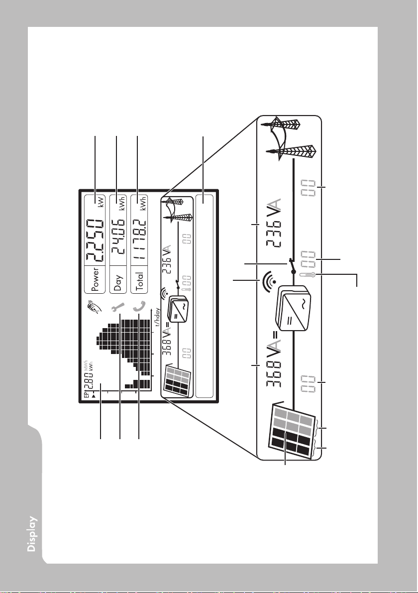
Tapping on the lower lid:
• Activating the background illumination
• Switching through the energy values of the past 16 feed-in hours to
the daily energy values of the past 16 days
• Switching through the line display
Current output
Daily energy
Total energy generated since the
Sunny Boy was installed
Text line for displaying an event
Bluetooth connection to other Sunny Boys
Input voltage / input current
Grid relay
Grid event number
Sunny Boy event number
Power reduction due to excessive temperature
• Cleaning the fan, if necessary (only for Sunny Boy 4000TL/5000TL)
• Sunny Boy might need better ventilation
PV generator event number
Sunny Boy 4000TL / 5000TL:
switching between input A and B
every 10 seconds
Sunny Boy 3000TL: no switching
Power range of the past 16 feed-in hours or
energy yield of past 16 days (switching the
display is done by tapping on the display)
Failure that can be removed on-site
(see chapter 10.2 )
Device fault:
Contact the SMA Serviceline.
Output voltage / output current
AB
Page 3

SMA Solar Technology AG Table of Contents
Table of Contents
1 Notes on this manual. . . . . . . . . . . . . . . . . . . . . . . . . . . . . . 6
1.1 Validity . . . . . . . . . . . . . . . . . . . . . . . . . . . . . . . . . . . . . . . . . . . . 6
1.2 Target group . . . . . . . . . . . . . . . . . . . . . . . . . . . . . . . . . . . . . . . . 6
1.3 Additional Information . . . . . . . . . . . . . . . . . . . . . . . . . . . . . . . . 6
1.4 Symbols Used . . . . . . . . . . . . . . . . . . . . . . . . . . . . . . . . . . . . . . . 7
2 Safety . . . . . . . . . . . . . . . . . . . . . . . . . . . . . . . . . . . . . . . . . . 8
2.1 Appropriate usage . . . . . . . . . . . . . . . . . . . . . . . . . . . . . . . . . . . 8
2.2 Safety instructions . . . . . . . . . . . . . . . . . . . . . . . . . . . . . . . . . . . 11
2.3 Explanation of Symbols . . . . . . . . . . . . . . . . . . . . . . . . . . . . . . 12
2.3.1 Symbols on the Inverter. . . . . . . . . . . . . . . . . . . . . . . . . . . . . . . . . . . . . . . . . 12
2.3.2 Symbols on the Type Label . . . . . . . . . . . . . . . . . . . . . . . . . . . . . . . . . . . . . . 13
3 Unpacking. . . . . . . . . . . . . . . . . . . . . . . . . . . . . . . . . . . . . . 14
3.1 Scope of delivery . . . . . . . . . . . . . . . . . . . . . . . . . . . . . . . . . . . 14
3.2 Identifying the Inverter . . . . . . . . . . . . . . . . . . . . . . . . . . . . . . . 14
4 Mounting. . . . . . . . . . . . . . . . . . . . . . . . . . . . . . . . . . . . . . . 15
4.1 Safety . . . . . . . . . . . . . . . . . . . . . . . . . . . . . . . . . . . . . . . . . . . . 15
4.2 Selecting the Mounting Location. . . . . . . . . . . . . . . . . . . . . . . . 15
4.3 Mounting the Inverter with the Wall Mounting Bracket . . . . . . 17
4.4 Mounting the inverter with a top hat rail. . . . . . . . . . . . . . . . . . 21
5 Electrical Connection . . . . . . . . . . . . . . . . . . . . . . . . . . . . . 24
5.1 Safety . . . . . . . . . . . . . . . . . . . . . . . . . . . . . . . . . . . . . . . . . . . . 24
5.2 Overview of the Connection Area . . . . . . . . . . . . . . . . . . . . . . 24
5.3 Connection to the Power Distribution Grid (AC). . . . . . . . . . . . 26
5.3.1 Conditions for the AC Connection . . . . . . . . . . . . . . . . . . . . . . . . . . . . . . . . 26
5.3.2 Connecting the Inverter to the Public Grid (AC) . . . . . . . . . . . . . . . . . . . . . . 29
5.3.3 Additional Grounding of the Enclosure. . . . . . . . . . . . . . . . . . . . . . . . . . . . . 32
Installation Guide SB30TL_40TL_50TL-IA-IEN120231 3
Page 4

Table of Contents SMA Solar Technology AG
5.4 Connection of the PV Generator (DC) . . . . . . . . . . . . . . . . . . . 33
5.4.1 Conditions for the DC connection for Sunny Boy 3000TL . . . . . . . . . . . . . . 33
5.4.2 Conditions for the DC connection for Sunny Boy 4000TL/5000TL . . . . . . . 34
5.4.3 Assembling the DC plug connector. . . . . . . . . . . . . . . . . . . . . . . . . . . . . . . . 36
5.4.4 Opening the DC Plug Connector . . . . . . . . . . . . . . . . . . . . . . . . . . . . . . . . . 38
5.4.5 Connecting the PV Generator (DC) . . . . . . . . . . . . . . . . . . . . . . . . . . . . . . . 39
5.5 Setting the Country Standard and Display Language . . . . . . . 42
5.5.1 Checking the Country Standard . . . . . . . . . . . . . . . . . . . . . . . . . . . . . . . . . . 44
5.5.2 Setting the Country Standard and Language using Rotary Switches . . . . . . 47
5.6 Communication. . . . . . . . . . . . . . . . . . . . . . . . . . . . . . . . . . . . . 48
5.6.1 Bluetooth . . . . . . . . . . . . . . . . . . . . . . . . . . . . . . . . . . . . . . . . . . . . . . . . . . 48
5.6.2 Multi-function relay . . . . . . . . . . . . . . . . . . . . . . . . . . . . . . . . . . . . . . . . . . . . 49
5.6.3 Communication module . . . . . . . . . . . . . . . . . . . . . . . . . . . . . . . . . . . . . . . . 52
6 Commissioning . . . . . . . . . . . . . . . . . . . . . . . . . . . . . . . . . . 53
6.1 Commissioning the Inverter. . . . . . . . . . . . . . . . . . . . . . . . . . . . 53
6.2 Display Messages during Initialization . . . . . . . . . . . . . . . . . . . 54
6.3 Self-Test in accordance with DK 5940, Ed. 2.2
(Applies to Italy Only). . . . . . . . . . . . . . . . . . . . . . . . . . . . . . . . 55
6.3.1 Starting the Self-Test . . . . . . . . . . . . . . . . . . . . . . . . . . . . . . . . . . . . . . . . . . . 55
6.3.2 Test Sequence . . . . . . . . . . . . . . . . . . . . . . . . . . . . . . . . . . . . . . . . . . . . . . . . 56
6.3.3 Interruption of the Self-Test . . . . . . . . . . . . . . . . . . . . . . . . . . . . . . . . . . . . . . 59
6.3.4 Restarting the Self-Test. . . . . . . . . . . . . . . . . . . . . . . . . . . . . . . . . . . . . . . . . . 59
7 Opening and closing . . . . . . . . . . . . . . . . . . . . . . . . . . . . . 60
7.1 Safety . . . . . . . . . . . . . . . . . . . . . . . . . . . . . . . . . . . . . . . . . . . . 60
7.2 Opening the Inverter. . . . . . . . . . . . . . . . . . . . . . . . . . . . . . . . . 61
7.3 Closing the Inverter. . . . . . . . . . . . . . . . . . . . . . . . . . . . . . . . . . 64
8 Maintenance and cleaning . . . . . . . . . . . . . . . . . . . . . . . . 66
8.1 Checking Heat Dissipation . . . . . . . . . . . . . . . . . . . . . . . . . . . . 66
8.1.1 Clean fan (only with Sunny Boy 4000TL/5000TL). . . . . . . . . . . . . . . . . . . . 66
8.1.2 Check fan (only with Sunny Boy 4000TL/5000TL) . . . . . . . . . . . . . . . . . . . 68
4 SB30TL_40TL_50TL-IA-IEN120231 Installation Guide
Page 5

SMA Solar Technology AG Table of Contents
8.2 Checking the Electronic Solar Switch (ESS) for Wear . . . . . . . 69
9 Slot for SD card . . . . . . . . . . . . . . . . . . . . . . . . . . . . . . . . . 70
10 Messages . . . . . . . . . . . . . . . . . . . . . . . . . . . . . . . . . . . . . . 71
10.1 Event messages. . . . . . . . . . . . . . . . . . . . . . . . . . . . . . . . . . . . . 71
10.2 Error messages . . . . . . . . . . . . . . . . . . . . . . . . . . . . . . . . . . . . . 72
11 Troubleshooting . . . . . . . . . . . . . . . . . . . . . . . . . . . . . . . . . 79
11.1 Checking the PV Generator for a Ground Fault . . . . . . . . . . . . 79
11.2 Checking the Function of the Varistors . . . . . . . . . . . . . . . . . . . 81
12 Decommissioning . . . . . . . . . . . . . . . . . . . . . . . . . . . . . . . . 85
12.1 Dismantling the Inverter. . . . . . . . . . . . . . . . . . . . . . . . . . . . . . . 85
12.2 Replacing the Enclosure Lid . . . . . . . . . . . . . . . . . . . . . . . . . . . 85
12.3 Packaging the Inverter . . . . . . . . . . . . . . . . . . . . . . . . . . . . . . . 87
12.4 Storing the Inverter . . . . . . . . . . . . . . . . . . . . . . . . . . . . . . . . . . 87
12.5 Disposing of the Inverter . . . . . . . . . . . . . . . . . . . . . . . . . . . . . . 87
13 Technical data. . . . . . . . . . . . . . . . . . . . . . . . . . . . . . . . . . . 88
13.1 Sunny Boy 3000TL . . . . . . . . . . . . . . . . . . . . . . . . . . . . . . . . . . 88
13.2 Sunny Boy 4000TL . . . . . . . . . . . . . . . . . . . . . . . . . . . . . . . . . . 92
13.3 Sunny Boy 5000TL . . . . . . . . . . . . . . . . . . . . . . . . . . . . . . . . . . 96
14 Accessories . . . . . . . . . . . . . . . . . . . . . . . . . . . . . . . . . . . . 100
15 Contact . . . . . . . . . . . . . . . . . . . . . . . . . . . . . . . . . . . . . . . 101
Installation Guide SB30TL_40TL_50TL-IA-IEN120231 5
Page 6

Notes on this manual SMA Solar Technology AG
1 Notes on this manual
1.1 Validity
This manual describes the assembly, installation, commissioning and maintenance of the following
SMA inverters:
• Sunny Boy 3000TL (SB 3000TL-20)
• Sunny Boy 4000TL (SB 4000TL-20)
• Sunny Boy 5000TL (SB 5000TL-20)
Keep this guide in a convenient place for future reference.
1.2 Target group
This manual is for qualified electricians. The tasks described in this manual may be performed by
electrically qualified persons only.
1.3 Additional Information
You will find further information on special topics such as designing a line circuit breaker or the
description of the parameters and measurement readings in the download area at www.SMA.de/en.
Refer to the User Manual provided for detailed information on operating the inverter.
6 SB30TL_40TL_50TL-IA-IEN120231 Installation Guide
Page 7
SMA Solar Technology AG Notes on this manual
1.4 Symbols Used
The following types of safety precautions and general information are used in this manual:
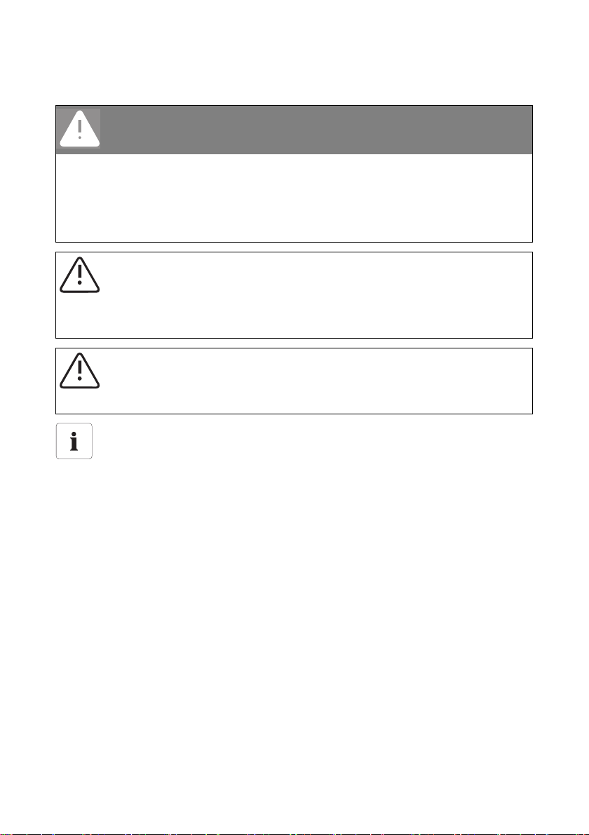
DANGER!
DANGER indicates a hazardous situation which, if not avoided, will result in death or
serious injury.
WARNING!
WARNING indicates a safety instruction, the failure to observe which will result in
immediate death or serious injury.
CAUTION!
CAUTION indicates a hazardous situation which, if not avoided, could result in minor or
moderate injury.
NOTICE!
NOTICE indicates a situation that can result in property damage if not avoided.
Information
Information provides tips that are valuable for the optimal installation and operation of
your product.
☑ This symbol indicates the result of an action.
Installation Guide SB30TL_40TL_50TL-IA-IEN120231 7
Page 8
Safety SMA Solar Technology AG
2 Safety
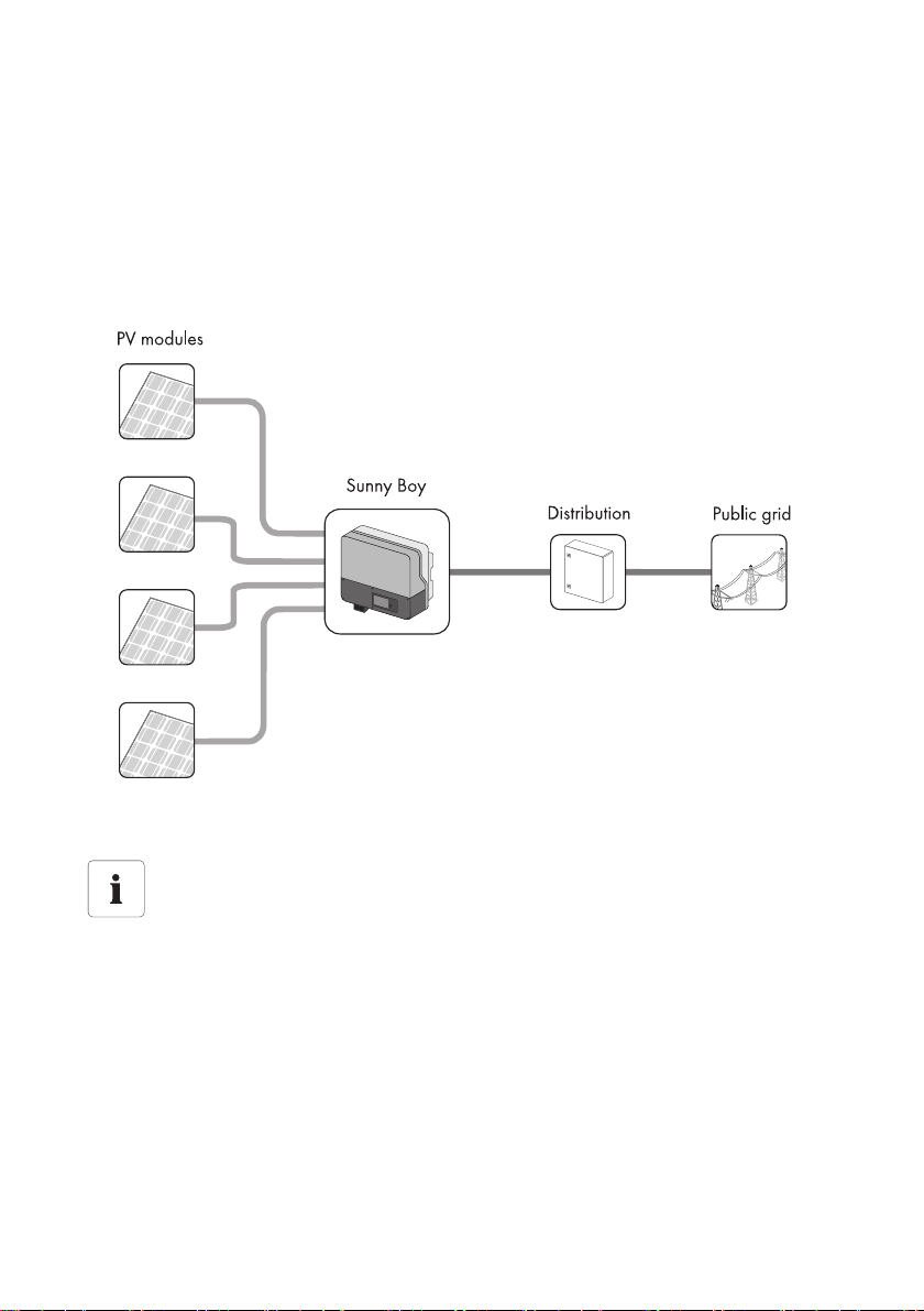
2.1 Appropriate usage
The Sunny Boy is a PV inverter which converts the DC current of a PV generator into AC current and
feeds it into the public grid.
Principle of a PV System with this Sunny Boy
The inverter may only be operated with PV generators (PV modules and cabling) of protection class
II. Do not connect any sources of energy other than PV modules to the inverter.
Capacitive Discharge Currents
PV modules with large capacities relative to ground, such as thin-film modules with cells on
a metallic substrate, are only to be implemented if their coupling capacity does not exceed
1,400 nF.
During grid feeding, a discharge current flows from the cells to ground. The amount of
current depends on the manner in which the modules are installed (e.g. foil on metal roof)
and on the weather (rain, snow). This "normal" discharge current may not exceed 50 mA
due to the fact that the inverter would otherwise automatically disconnect from the grid as
a protective measure. For further information on this subject, see the Technical Information
"Capacitive Discharge Currents" in the download area at www.SMA.de/en.
8 SB30TL_40TL_50TL-IA-IEN120231 Installation Guide
Page 9

SMA Solar Technology AG Safety
When designing the PV system, ensure that the values comply with the permitted operating range of all
components at all times. The free design program "Sunny Design" (www.SMA.de/en/SunnyDesign) will
assist you. The manufacturer of the PV modules must have approved the modules for use with this inverter.
You must also ensure that all measures recommended by the module manufacturer for long-term
maintenance of the module properties are taken (see also Technical Information "Module Technology",
in the download area of www.SMA.de/en).
Do not use the inverter for purposes other than those described here. Alternative uses, modifications
to the inverter or the installation of components not expressly recommended or sold by
SMA Solar Technology AG void the warranty claims and operation permission.
Installation Guide SB30TL_40TL_50TL-IA-IEN120231 9
Page 10

Safety SMA Solar Technology AG
Certified Countries
The Sunny Boy 3000TL/4000TL/5000TL (with according configuration) fulfill the requirements
specified in the following standards and directives (dated: 2010/11):
• VDE 0126-1-1 (02.2006)
• C10/C11 (2009/05)*
• PPC (2006/06)
•PPDS
• DK 5940 Ed. 2.2 (2006/02)
• EN 50438
• I.S. EN 50438**
• NEN EN 50438
• MSA EN 50438
• SS-EN 50438
• UTE C15-712-1
• RD 1663/2000 (2000)***
• RD 661/2007***
• G83/1-1 (2003/09)
• AS4777 (2005)
• IEC-utility Meeting 216
• KEMCO PV501 (2008) (only applies for SB 3000TL-20/V 0158)
* Only possible when the phase voltage is 230 V.
** On request
*** In the event of restrictions in certain regions, contact the SMA Serviceline.
SMA Solar Technology AG can preset special grid parameters for other countries/installation
locations according to customer requests, after evaluation by SMA Solar Technology AG.
You can make later modifications yourself by changing software parameters with respective
communication products (e.g. Sunny WebBox or Sunny Explorer). To change grid-relevant
parameters, you need a personal access code - the so-called SMA Grid Gua rd Code. The applica tio n
form for the personal access code is located in the download area at www.SMA.de/en, in the
"Certificate" category for each inverter.
10 SB30TL_40TL_50TL-IA-IEN120231 Installation Guide
Page 11
SMA Solar Technology AG Safety
2.2 Safety instructions
DANGER!
Danger to life due to high voltages in the inverter.
• All work on the inverter may only be carried out by qualified personnel.
• T he a ppl iance is not to b e used by childre n or per son s with re duced physical, sensory
or mental capabilities, or lack of experience and knowledge, unless they have been
given supervision or instruction.
• Children should be supervised to ensure that they do not play with the appliance.
CAUTION!
Parts of the enclosure can become hot - risk of burn injuries!
During operation, the upper lid of the enclosure and the enclosure body may become hot.
• Only touch the lower enclosure lid during operation.
CAUTION!
Possible damage to health as a result of the effects of radiation!
• Do not stay closer than 20 cm to the inverter for any length of time.
Grounding the PV generator
Comply with the local regulations for grounding the modules and the PV generator.
SMA Solar Technology AG recommends connecting the generator frame and other
electrically conductive surfaces in a manner which ensures continuous conduction, and
grounding these to ensure maximum protection for systems and personnel.
Installation Guide SB30TL_40TL_50TL-IA-IEN120231 11
Page 12
Safety SMA Solar Technology AG
2.3 Explanation of Symbols
This section gives an explanation of all the symbols found on the inverter and on the type label.
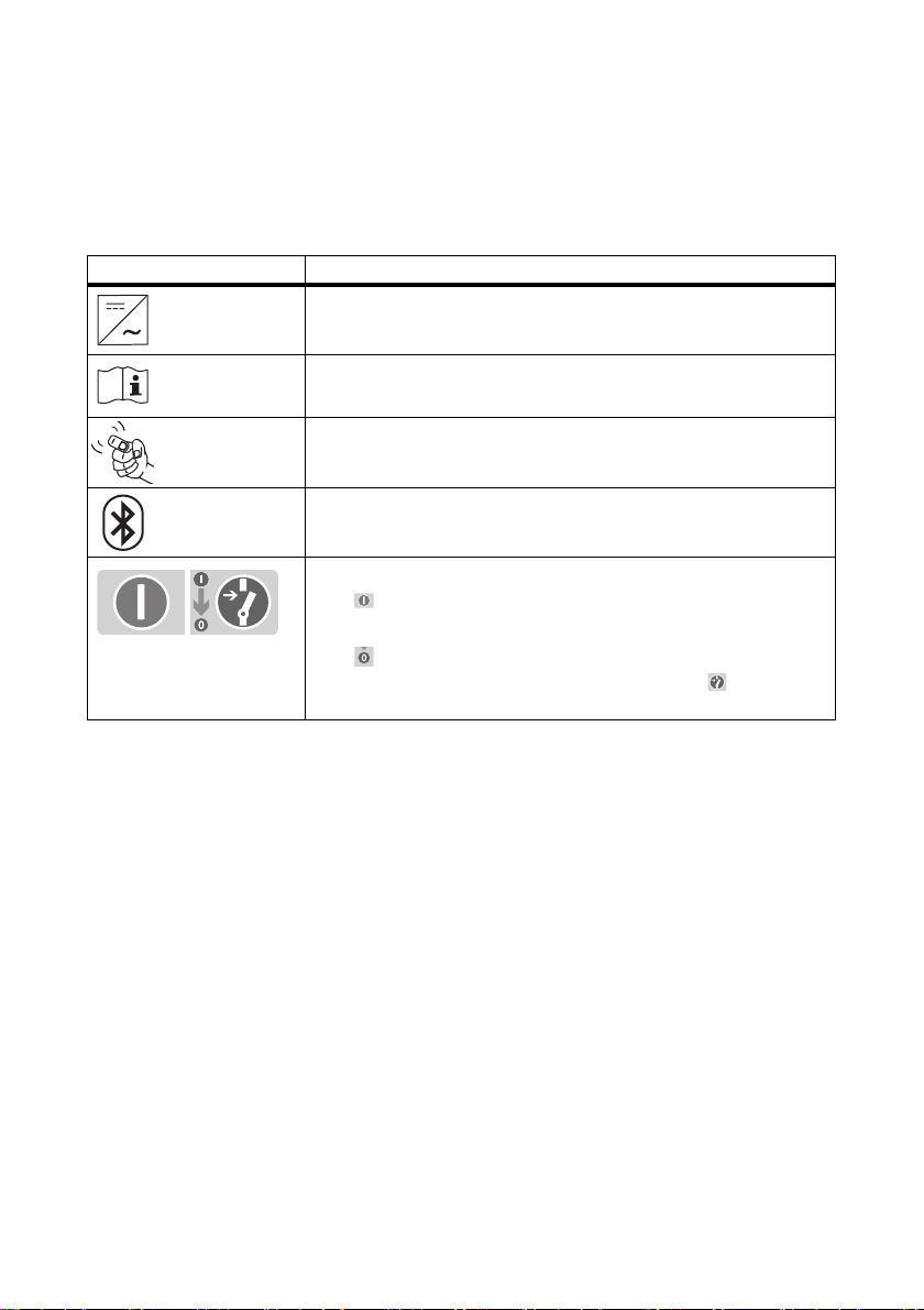
2.3.1 Symbols on the Inverter
Icon Explanation
Operation Display.
Indicates the operation condition of the inverter.
An error has occurred.
Read section 11”Troubleshooting” (page79) to remedy the error.
Tap to switch on the display light and switch to the next display
message.
Bluetooth
Shows the status of Bluetooth Communication.
Electronic Solar Switch (ESS) DC load disconnection unit
®
Wireless Technology.
• Wh en t he E lect ron ic S ola r Sw itc h is p lug ged in, the D C ci rcu it
is closed.
• To int err upt the DC c ircuit a nd d isconne ct t he inver ter securely
under load, you have to disconnect the inverter as described
in section 7.2”Opening the Inverter” (page61).
12 SB30TL_40TL_50TL-IA-IEN120231 Installation Guide
Page 13
SMA Solar Technology AG Safety
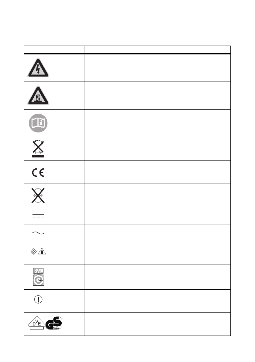
2.3.2 Symbols on the Type Label
Icon Explanation
Beware of dangerous electrical voltage.
The inverter operates at high voltages. All work on the inverter may
only be carried out by qualified personnel.
Beware of hot surface.
The inverter can become hot during operation. Avoid contact during
operation.
Observe all documentation that accompanies the inverter.
The inverter must not be disposed of together with household waste.
For more information on disposal, see section 12.5”Disposing of the
Inverter” (page87).
CE mark.
The inverter complies with the requirements of the applicable EC
guidelines.
The inverter is transformerless.
Direct Current (DC)
Alternating current (AC)
Protection rating IP54.
The inverter is protected against dust deposits in the interior and
against splashes of water from all angles.
RAL quality mark for solar products.
The inverter complies with the requirements of the German Institute for
Quality Assurance and Labeling.
Device class label.
The product is equipped with a wireless component that complies with
the harmonized standards.
Certified safety
The inverter complies with the requirements of the Equipment and
Product Safety Act in Europe.
Installation Guide SB30TL_40TL_50TL-IA-IEN120231 13
Page 14
Unpacking SMA Solar Technology AG
3 Unpacking
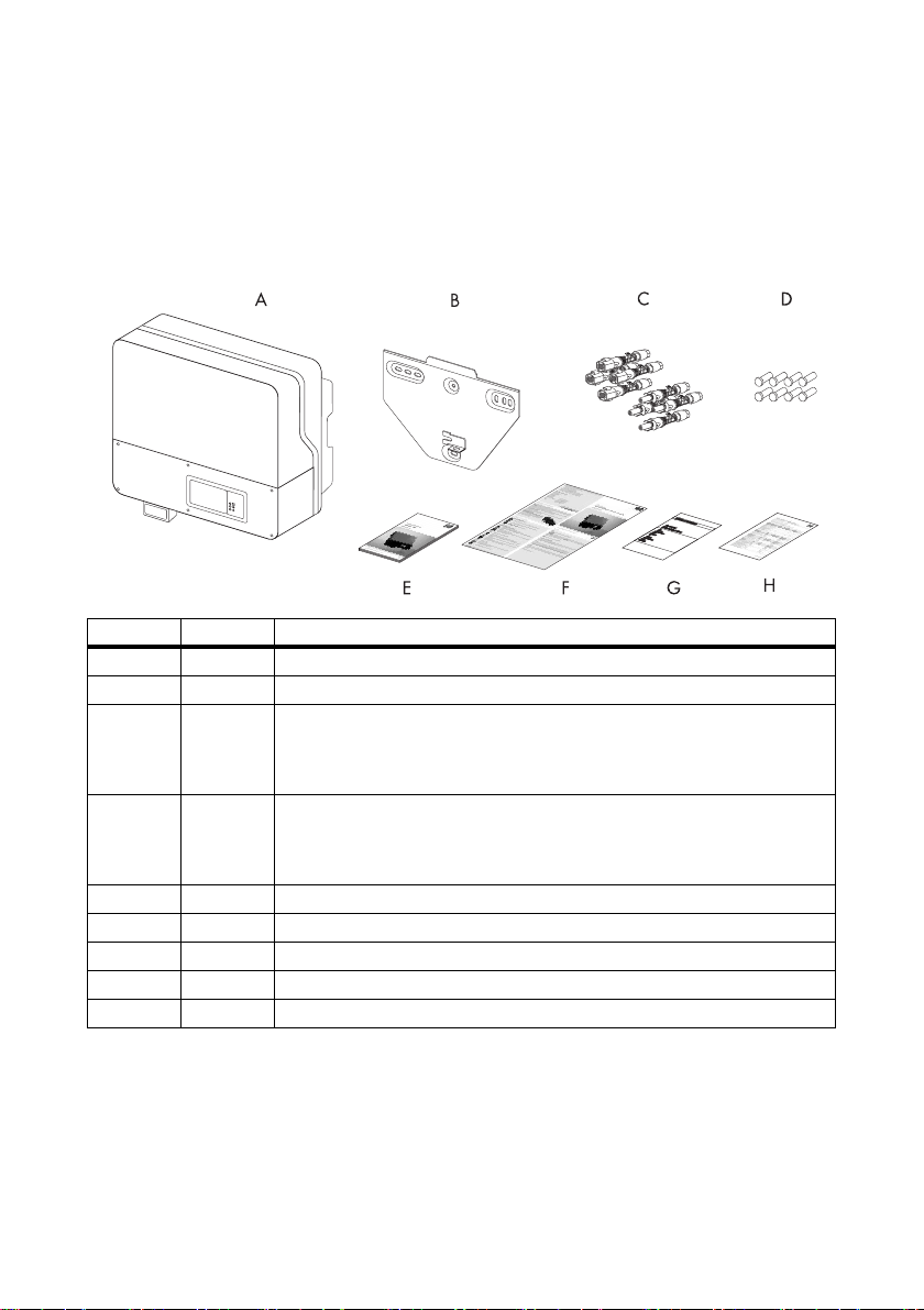
3.1 Scope of delivery
Check the delivery for completeness and any visible external damage. Contact your dealer if anything
is damaged or missing.
Object Number Description
A 1 Sunny Boy
B 1 Wall-mounting bracket
C 4/8 DC plug connector
Sunny Boy 3000TL: 4 units (2 x positive, 2 x negative)
Sunny Boy 4000TL/5000TL: 8 units (4 x positive, 4 x negative)
D 4/8 Sealing plugs for DC plug connectors
Sunny Boy 3000TL: 4 units
Sunny Boy 4000TL/5000TL: 8 units
E 1 Installation Guide
F 1User Manual
G 1 Set of documents with explanations and certificates
H 1 Supplementary sheet with inverter factory settings
optional 1 Installation Guide for communication module
3.2 Identifying the Inverter
You can identify the inverter using the type label. The type plate is on the right side of the enclosure.
The serial number (Serial no.) and the type (Type/Model) of the product, as well as device-specific
characteristics are specified on the type label.
14 SB30TL_40TL_50TL-IA-IEN120231 Installation Guide
Page 15
SMA Solar Technology AG Mounting
4 Mounting
4.1 Safety
DANGER!
Danger to life due to fire or explosion.
Despite careful construction, electrical devices can cause fires.
• Do not mount the inverter on flammable construction materials.
• Do not mount the inverter in areas where highly flammable materials are stored.
• Do not mount the inverter in areas with a risk of explosion.
CAUTION!
Parts of the enclosure can become hot - risk of burn injuries!
• Mount the inverter in such a way that it cannot be touched inadvertently during
operation.
CAUTION!
Risk of injury due to the heavy weight of the inverter.
• Take the inverter's weight of approx. 25 kg into account for mounting.
4.2 Selecting the Mounting Location
Consider the following points when selecting where to install:
• The mounting method and location must be suitable for the inverter's weight and dimensions
(see section 13”Technical data” (page88)).
• Mount on a solid surface.
• The mounting location must at all times be clear and have safe access without the use of
additional aids such as scaffolding or lifting platforms. Any possible service actions are
otherwise limited.
Installation Guide SB30TL_40TL_50TL-IA-IEN120231 15
Page 16
Mounting SMA Solar Technology AG
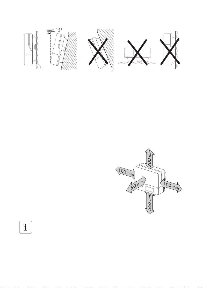
• Mount vertically or tilted backward by max. 15°.
• The connection area must point downwards.
• Never mount the device with a forward tilt.
• Never install the device with a sideways tilt.
• Do not mount horizontally.
• Mount at eye level to allow operating status to be read at all times.
• The ambient temperature should be below 40 °C to ensure optimal operation.
• Do not expose the inverter to direct sunlight to avoid power reduction due to excessive heating.
• I n li vin g areas , do not mou nt t he unit on p las ter boa rd wall s or similar to avoid audible vibrations.
The inverter can make noises when in use, which may be perceived as a nuisance in a living
area.
• Observe the minimum clearances to walls, other
inverters, or objects as shown in the diagram in
order to ensure sufficient heat dissipation and
sufficient space for removing the Electronic Solar
Switch.
Multiple inverters installed in areas with high ambient temperatures
There must be sufficient clearance between the individual inverters to ensure the cooling air
from the adjacent inverter flows freely.
If necessary, increase the clearance spaces and make sure there is enough ventilation to
ensure sufficient cooling of the inverters.
16 SB30TL_40TL_50TL-IA-IEN120231 Installation Guide
Page 17
SMA Solar Technology AG Mounting
4.3 Mounting the Inverter with the Wall Mounting Bracket
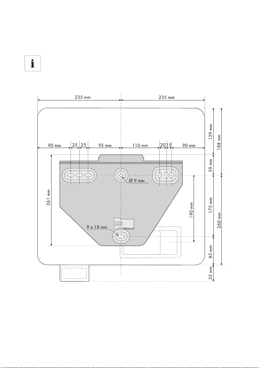
1. Use the wall mounting bracket as a drilling template and mark the positions of the drill holes.
Number of drill holes used
• When mounting onto the wall, use at least 2 of the horizontal holes and the lowest
hole in the middle.
• Use the two holes in the center when mounting the device to a pillar.
Installation Guide SB30TL_40TL_50TL-IA-IEN120231 17
Page 18
Mounting SMA Solar Technology AG
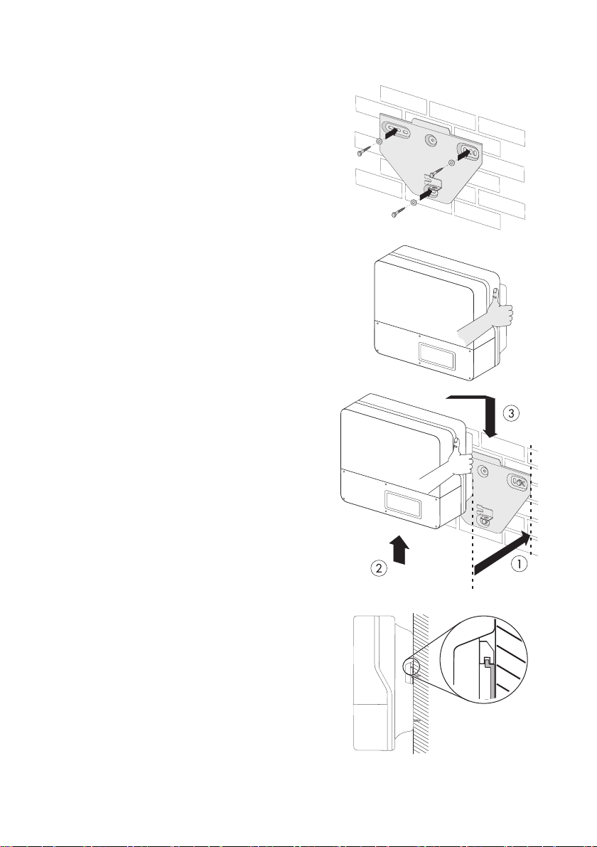
2. At tac h the wa ll m oun ting bra cke t using app rop ria te
screws (diameter min. 6 mm) and washers (outer
diameter min. 18 mm).
3. Transport the inverter using the grip recesses on the
sides.
4. Attach the inverter to the wall bracket slightly to the
left of its final position.
The right edge of the rear panel of the inverter has
to be flush with the right edge of the wall mounting
bracket.
5. Check both sides of the inverter to ensure that it is
correctly in place.
18 SB30TL_40TL_50TL-IA-IEN120231 Installation Guide
Page 19
SMA Solar Technology AG Mounting
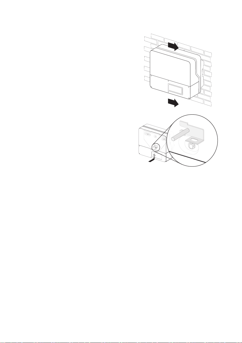
6. Push the inverter to the right on the wall mounting
bracket, until it locks into place with the locking bolt
on the back wall.
7. Check to ensure that the inverter is correctly seated.
☑ The inverter is now securely mounted to the wall.
Installation Guide SB30TL_40TL_50TL-IA-IEN120231 19
Page 20
Mounting SMA Solar Technology AG
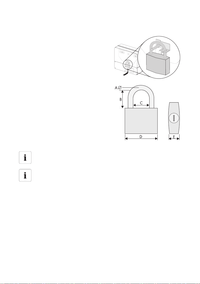
Optional Theft Protection
To protect the inverter from theft, you can lock it to the
wall mounting bracket with a padlock.
The lock must meet the following requirements:
•Size:
A: 6 mm … 10 mm diameter
B: 21 mm … 35 mm
C: 20 mm … 33 mm
D: 40 mm … 60 mm
E: 13 mm … 21 mm
•Stainless
• Hardened shackle
• Secured lock cylinder
Storage of the key
Store the key carefully for possible service purposes.
Outdoor Installation
Always use a lock suitable for outdoor installation. Regularly check the correct function of
the padlock.
20 SB30TL_40TL_50TL-IA-IEN120231 Installation Guide
Page 21
SMA Solar Technology AG Mounting
4.4 Mounting the inverter with a top hat rail
Requirements for installing the top hat rail
• Use a TH-35-7.5 supporting rail compliant with DIN EN 60715.
• Use stainless steel top hat rail and screws to prevent contact corrosion.
• Install on level ground only.
• Use fastening material suitable for the surface. Please observe the weight of the inverter.
Procedure
1. Use the top hat rail as a drilling template and mark the positions of the drill holes.
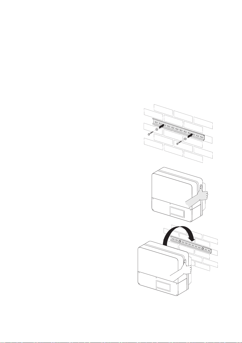
2. Attach the top-hat rail using appropriate screws
(diameter min. 6 mm) and washers (outer diameter
min. 18 mm).
Secure one screw at least every 300 mm.
3. Transport the inverter using the grip recesses on the
sides.
4. Suspend the inverter on the top hat rail using the
opening on its rear wall.
Installation Guide SB30TL_40TL_50TL-IA-IEN120231 21
Page 22
Mounting SMA Solar Technology AG
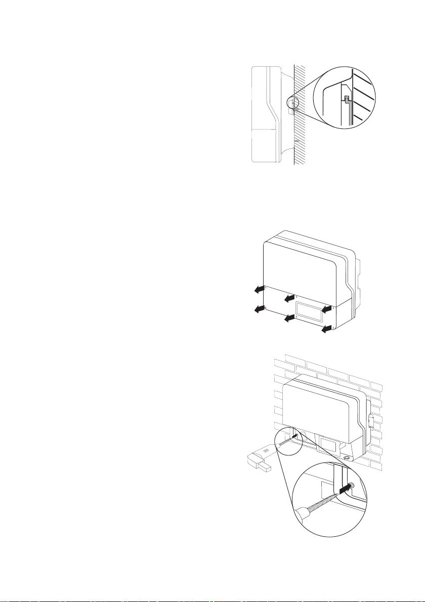
5. Check both sides of the inverter to ensure that it is
correctly in place.
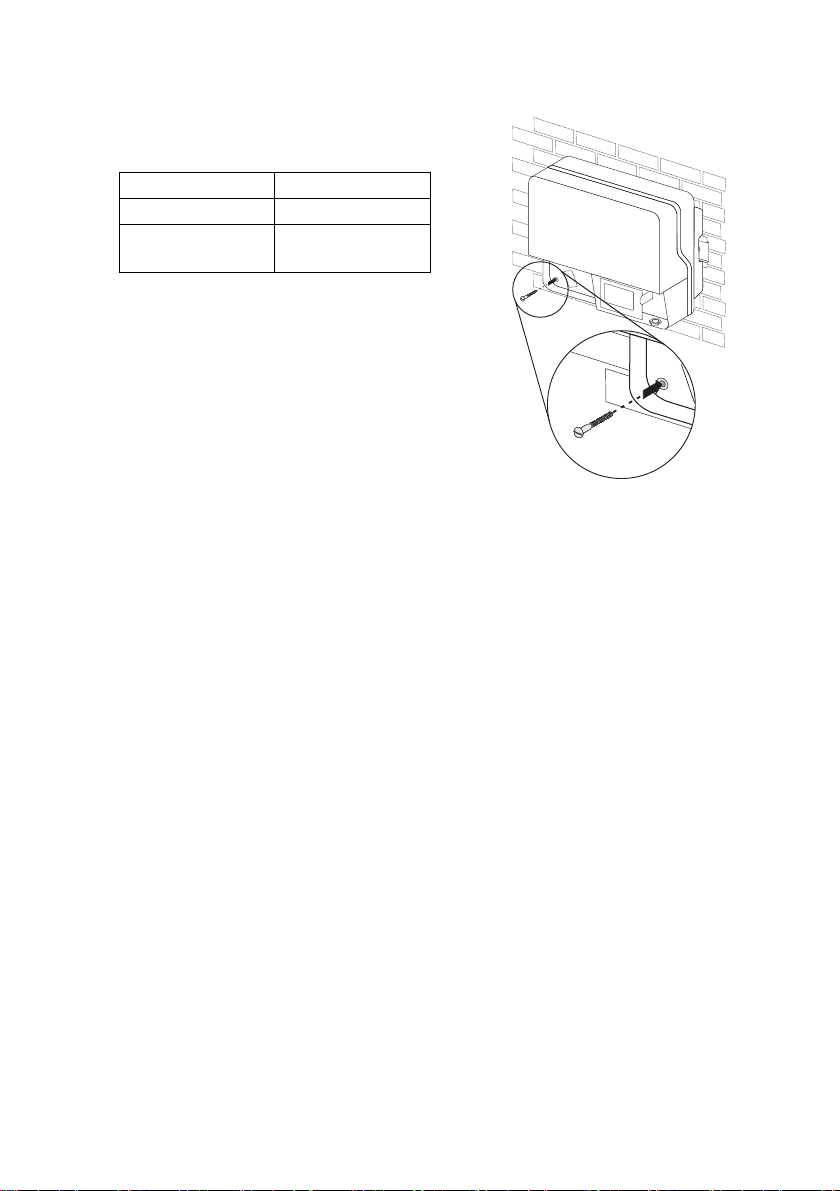
Securing the Inverter Against Excavation
Additionally secure the inverter in the wall using screws.
1. Remove the Electronic Solar Switch downwards.
2. Loosen all 6 captive screws and remove lid.
3. Drill through the back wall of the enclosure.
4. Use a suitable drill bit with a minimum length of
120 mm.
5. Insert suitable wall anchor.
22 SB30TL_40TL_50TL-IA-IEN120231 Installation Guide
Page 23
SMA Solar Technology AG Mounting
6. Fasten the inverter.
The screw must meet the following requirements:
Length: at least 100 mm
Diameter: 8 mm
Screw head No outside hexagon,
no countersunk head
☑ The inverter is protected against excavation.
Installation Guide SB30TL_40TL_50TL-IA-IEN120231 23
Page 24
Electrical Connection SMA Solar Technology AG
5 Electrical Connection
5.1 Safety
NOTICE!
Damage to the inverter through electrostatic discharges.
Internal components of the inverter can be irreparably damaged by static discharge.
• Ground yourself before you touch a component.
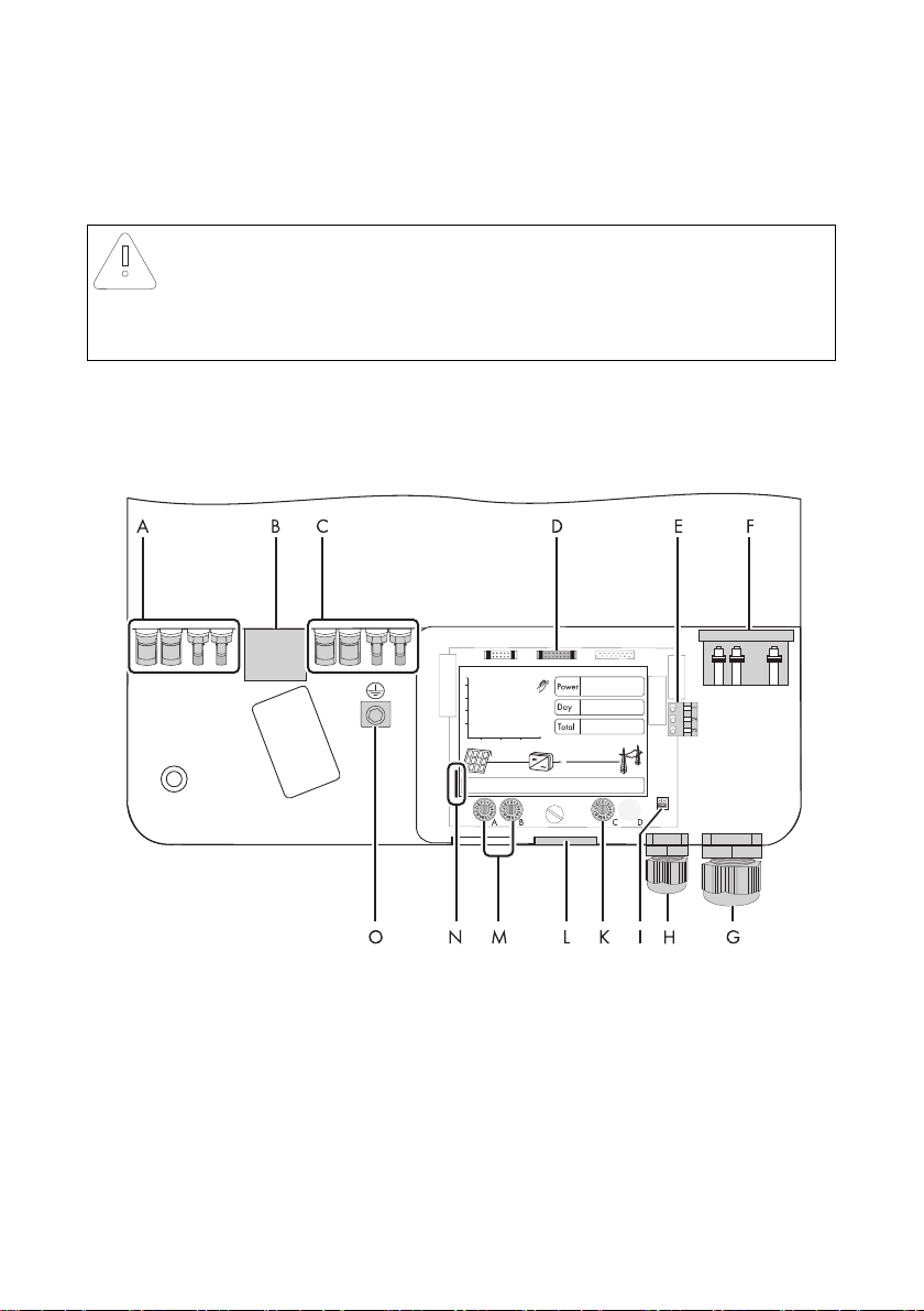
5.2 Overview of the Connection Area
The following figure shows the assignment of the individual connection areas, enclosure openings and
cable glands of the inverter.
24 SB30TL_40TL_50TL-IA-IEN120231 Installation Guide
Page 25
SMA Solar Technology AG Electrical Connection
Object Description
A DC plug connectors for connecting the strings (input zone A)
B Electronic Solar Switch (ESS) socket
C DC plug connectors for connecting the strings (input zone B) (only with Sunny Boy
4000TL/5000TL)
D Connector for optional communication via RS485
E Connection terminal for multi-function relays
F Terminals for grid connection (AC)
G Cable gland for grid connection (AC) (12 mm … 25 mm)
H Cable gland (6 mm … 12 mm) for the optional connection of the multi-function
relay
I Jumper slot for setting the language to English
K Rotary switch for the configuration of Bluetooth communication
L Enclosure opening for optional communication via RS485
M Rotary switch to set the country of installation and the display language
N Slot for SD card
O Ground terminal to additionally ground the inverter
Installation Guide SB30TL_40TL_50TL-IA-IEN120231 25
Page 26
Electrical Connection SMA Solar Technology AG
5.3 Connection to the Power Distribution Grid (AC)
5.3.1 Conditions for the AC Connection
• Comply with the connection requirements of your utility operator.
Residual current protective device
The inverter is equipped with an integrated all-pole sensitive failure current monitoring unit. The
inverter can automatically distinguish between real fault currents and "normal" capacitive leakage
currents.
If an external RCD or residual current breaker is strictly required, you must use a switch that triggers
at a failure current of 100 mA or higher.
Cable sizing
The grid impedance of the AC cable must not exceed 1 ohm. Otherwise, the inverter will disconnect
at full feed capacity due to excessive voltage at the feed-in point.
The conductor cross-section should be dimensioned such that cable losses do not exceed 1 % at
nominal power. Use "Sunny Design" (www.SMA.de/en/SunnyDesign) for this.
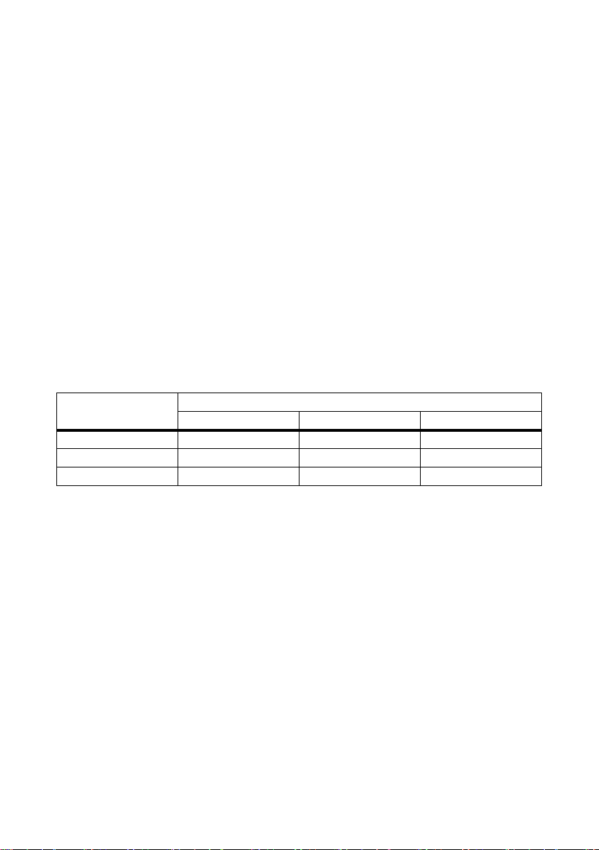
The maximum cable lengths relative to the conductor cross-section are shown in the following table.
Conductor crosssection
4.0 mm² 23.5 m Not recommended Not recommended
6.0 mm² 35.2 m 23.3 m 18.6 m
10.0 mm² 58.7 m 38.8 m 31.1 m
The conductor cross-section required in individual cases depends on the following factors, among
others:
• Ambient temperature,
•Routing method,
• Cable losses,
• Valid installation requirements of the respective country (installation location).
SB 3000TL-20 SB 4000TL-20 SB 5000TL-20
Maximum cable length
26 SB30TL_40TL_50TL-IA-IEN120231 Installation Guide
Page 27
SMA Solar Technology AG Electrical Connection
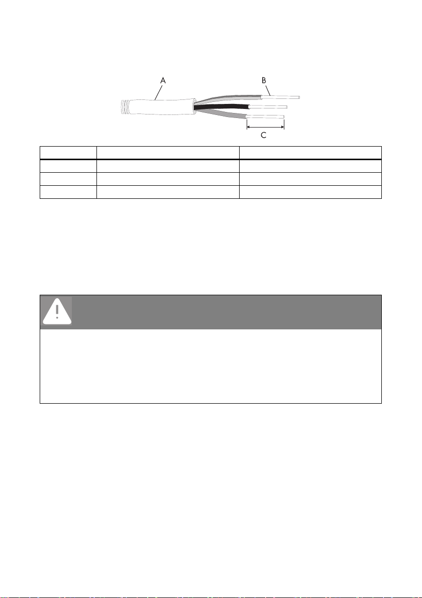
Cable Requirements
Object Description Value
A External diameter 12 mm ... 25 mm
B Cross-section of insulated conductor Max. 10 mm²
C Strip insulation Approx. 12 mm
Load disconnection unit
You must install a separate line circuit breaker for each inverter in order to ensure that the inverter
can be securely disconnected under load. The maximum permissible rating is located in section
13”Technical data” (page88).
Detailed information and examples for the design of a line circuit breaker can be found in the
Technical Information "Line Circuit Breaker" in the SMA Solar Technology AG download area at
www.SMA.de/en.
DANGER!
Danger to life due to fire.
When more than one inverter is connected to the same line circuit breaker, the protective
function of the line circuit breaker is no longer guaranteed. It can result in a cable fire or
the destruction of the inverter.
• Never connect several inverters to the same line circuit breaker.
• Observe the maximum permissible fuse protection of the inverter when selecting the
line circuit breaker.
Installation Guide SB30TL_40TL_50TL-IA-IEN120231 27
Page 28
Electrical Connection SMA Solar Technology AG
DANGER!
Danger to life due to fire.
Wh en a pro duc er ( inv ert er) and a co nsu mer are con nected t o th e same line circuit breaker,
the protective function of the line circuit breaker is no longer guaranteed. The current from
the inverter and the grid can accumulate to overcurrent which is not be detected by the line
circuit breaker.
• Never connect consumers between the
inverter and the line circuit breaker
without protection.
• Always protect consumers separately.
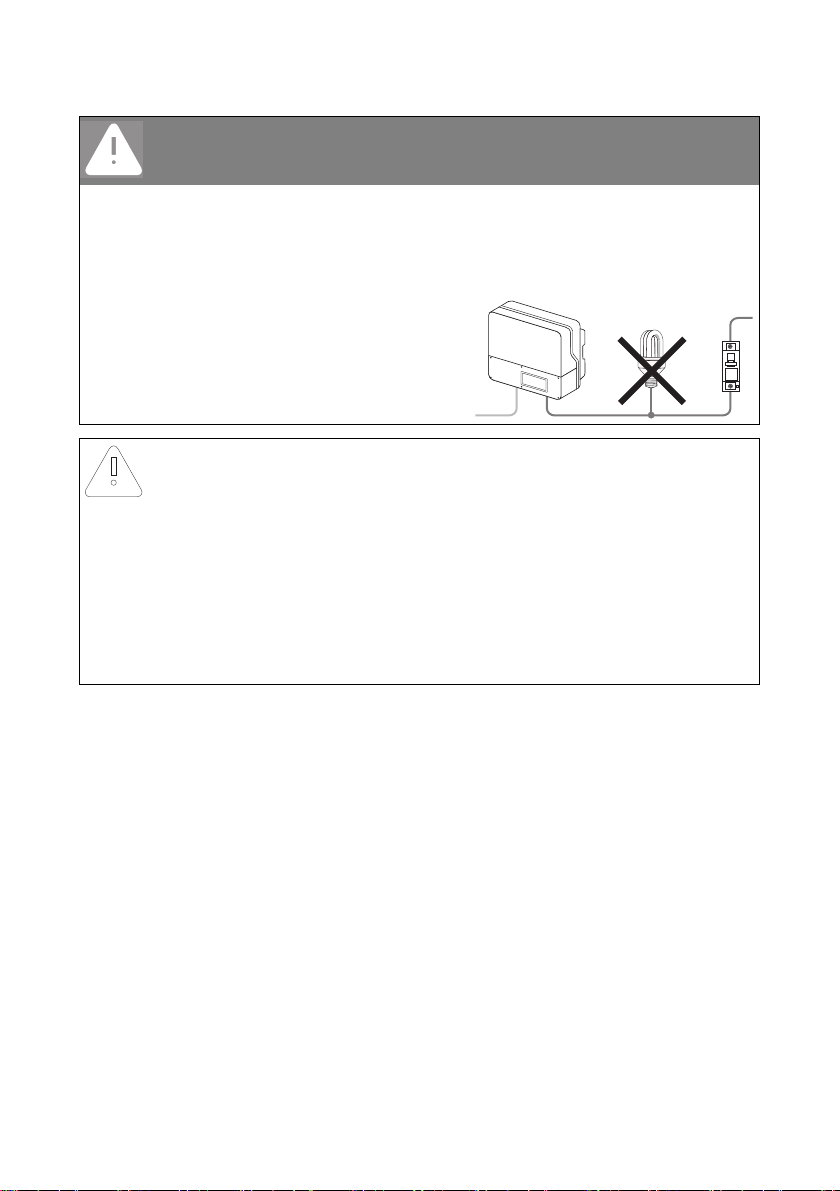
NOTICE!
Damage to the inverter by using screw type fuse elements as a load
disconnection unit.
A screw type fuse element, e.g. D system (Diazed) or D0 system (Neozed) is not a load
disconnection unit, and thus must not be used as a load disconnection unit. A screw type
fuse element is only used as cable protection.
When disconnecting under load using a screw type fuse element, the inverter can be
damaged.
• Use only a load disconnection switch or a line circuit breaker as a lo ad d isc onn ect ion
unit.
28 SB30TL_40TL_50TL-IA-IEN120231 Installation Guide
Page 29
SMA Solar Technology AG Electrical Connection
5.3.2 Connecting the Inverter to the Public Grid (AC)
1. Check that the grid voltage is within the permissible voltage range.
The exact operating range of the inverter is specified in the operation parameters. The
corresponding document is located in the download area at www.SMA.de/en, in the
"Technical Description" category of the respective inverter.
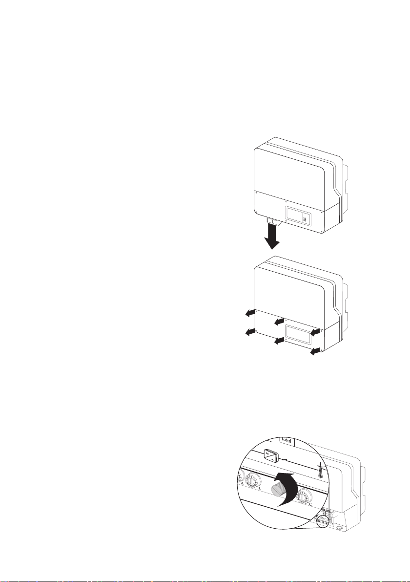
2. Disconnect the line circuit breaker and secure against re-connection.
3. Remove the Electronic Solar Switch.
4. Loosen all 6 captive screws and remove lid.
5. Check the correct country setting of the inverter using the supplement provided against the
factory settings.
If the inverter is not set to the desired country standard, then adjust the country standard as
de scr ibe d in sec tio n 5. 5.2”Se tti ng t he C oun try Sta nda rd a nd L ang uag e us ing Rot ary Swi tch es”
(page47).
6. Fo r ea sy c onnect ion , lo ose n the dis play scr ews until
the display raises.
– Flip up the display until it clicks into place.
Installation Guide SB30TL_40TL_50TL-IA-IEN120231 29
Page 30
Electrical Connection SMA Solar Technology AG
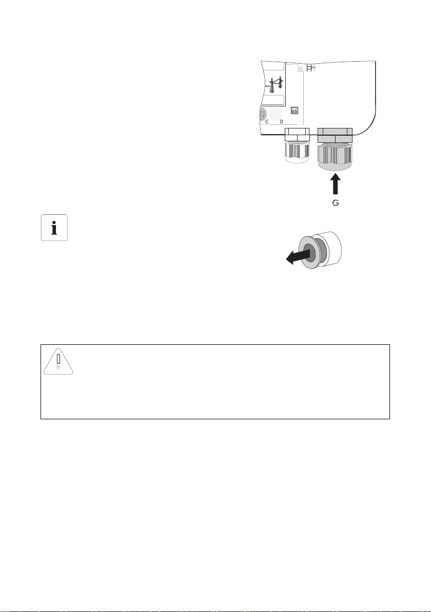
7. Unscrew the AC cable gland's lock nut (G) and
remove the filler-plug from the cable gland.
Seal in the AC cable gland
There is a two-part seal in the cable gland.
Remove the internal insert if necessary, e.g. to
lay a thicker cable.
The following guideline values apply:
• Cable cross-section with seal and insert: 12 mm … 16 mm
• Cable cross-section with seal only and without insert: 15 - 21 mm
8. Pull the cable through.
9. Raise the AC clamp terminals as far as they will go.
NOTICE!
Risk of fire when connecting 2 conductors to a single terminal
If 2 conductors are connected to one terminal, a poor electrical contact can result in
overheating or a risk of fire.
• Never connect more than one conductor per terminal.
30 SB30TL_40TL_50TL-IA-IEN120231 Installation Guide
Page 31

SMA Solar Technology AG Electrical Connection
10. Connect L, N and the protective conductor (PE) to
the AC terminal in accordance with the label.
To do t his , th e insula ted PE condu cto r mu st b e 5 mm
longer than the insulated L and N conductors!
L and N must not be swapped.
CAUTION!
Danger of crushing when terminals snap shut!
The terminals close by snapping down fast and hard.
• Press the terminals down with your thumb, do not grip the entire terminal on all sides.
• Keep fingers away from the terminals.
11. Close all terminals of the AC terminal again until they snap into place.
12. Fold down the display and screw it tightly.
13. Tighten the lock nut firmly to the cable gland.
DANGER!
Danger to life due to high voltages in the inverter.
• Do not switch on the line circuit breaker until the PV generator has been connected
and the inverter is securely closed.
☑ The inverter is now connected to the public grid (AC).
Installation Guide SB30TL_40TL_50TL-IA-IEN120231 31
Page 32

Electrical Connection SMA Solar Technology AG
5.3.3 Additional Grounding of the Enclosure
If a second protective conductor connection is required in the country of installation, you can also
ground the inverter using a second protective conductor on the connection terminal on the enclosure.
Procedure
1. Undo screw (A) by half way.
2. Insert the stripped grounding cable (D) under the
clamping clip (C) (max. cross-section 16 mm²).
3. Fasten terminal (C).
The toothing of the lock washer (B) must face
toward the terminal clamp.
☑ The inverter's enclosure is additionally grounded.
You can ground multiple inverters as shown in the diagram below:
32 SB30TL_40TL_50TL-IA-IEN120231 Installation Guide
Page 33

SMA Solar Technology AG Electrical Connection
5.4 Connection of the PV Generator (DC)
5.4.1 Conditions for the DC connection for Sunny Boy 3000TL
2 strings can be connected to the Sunny Boy 3000TL.
Use of Adaptors
Adaptors (branch connectors) must not be visible or freely accessible in the immediate
surroundings of the inverter.
• The DC circuit may not be interrupted by adaptors.
• Observe the procedure for disconnecting the inverter as described in section
7.2”Opening the Inverter” (page61).
• Requirements for the PV modules of the connected strings:
– Same type
–Same number
– Identical alignment
– Identical tilt
•The connecting cables of the PV modules must be fitted with plug connectors. You will find the
necessary DC plug connector for DC connection in the delivery.
Installation Guide SB30TL_40TL_50TL-IA-IEN120231 33
Page 34

Electrical Connection SMA Solar Technology AG
• The following limit values at the DC input of the inverter must not be exceeded:
maximum input voltage Maximum input current
550 V 17.0 A
5.4.2 Conditions for the DC connection for Sunny Boy 4000TL/5000TL
The inverter has two input zones "A" and "B", each with its own MPP tracker. 2 strings can be
connected to each input zone.
Use of Adaptors
Adaptors (branch connectors) must not be visible or freely accessible in the immediate
surroundings of the inverter.
• The DC circuit may not be interrupted by adaptors.
• Observe the procedure for disconnecting the inverter as described in section
7.2”Opening the Inverter” (page61).
34 SB30TL_40TL_50TL-IA-IEN120231 Installation Guide
Page 35

SMA Solar Technology AG Electrical Connection
• For each input zone (A or B), the following are the requirements for the PV modules of the
connected strings:
– Same type
–Same number
– Identical alignment
– Identical tilt
• When connecting just 2 identical strings, it is more efficient to connect these to only one input
zone also.
Exception: shaded strings or if the total input current is more than 15 A.
No mixed connections between input zones
,
For instance, if the positive pole of a string is connected at input zone A and the negative
pole at input zone B, this is called a mixed connection.
Only connect strings at one input zone and never mix the input zones A and B!
Otherwise, the inverter no longer fulfills the requirements of the EMC Directive (Directive
on the electromagnetic compatibility of a device) and therefore loses its operation license.
•The connecting cables of the PV modules must be fitted with plug connectors. You will find the
necessary DC plug connector for DC connection in the delivery.
• The following limit values at the DC input of the inverter must not be exceeded:
maximum input voltage Maximum input current
Input area A Input area B
550 V 15.0 A 15.0 A
Installation Guide SB30TL_40TL_50TL-IA-IEN120231 35
Page 36

Electrical Connection SMA Solar Technology AG
5.4.3 Assembling the DC plug connector
In order to connect to the inverter, all connection cables of the PV modules must be equipped with the
DC plug connectors provided.
To ass emb le t he D C pl ug c onne cto rs, pro cee d as fol low s: En sur e the plug connectors have the correct
polarity. The DC plug connectors have the symbols "+" and " − ".
Cable Requirements
• Use a PV1-F cable.
Procedure
1. Insert the stripped cable into the plug up to the limit.
2. Press the clamping clip down until it audibly snaps
into place.
3. Ensure the cable is correctly in place.
Result Measure
☑ If the conductors are visible in the hollow
cavity of the clamping clip, the cable is in
the correct position.
36 SB30TL_40TL_50TL-IA-IEN120231 Installation Guide
• Proceed to step 4.
Page 37

SMA Solar Technology AG Electrical Connection
Result Measure
☑ If the conductors are not visible in the
hollow cavity, the cable is not in the correct
position.
• Loosen the clamping bracket with the help
of a screwdriver. The width of the
screwdriver should be 3.5 mm.
• Remove cable and start again from step 1.
4. Push the threaded joint to the thread and screw into place with a torque of 2 Nm.
☑ The DC connectors are now assembled and can be connected to the inverters, as described in
section 5.4.5”Connecting the PV Generator (DC)” (page39).
Installation Guide SB30TL_40TL_50TL-IA-IEN120231 37
Page 38

Electrical Connection SMA Solar Technology AG
5.4.4 Opening the DC Plug Connector
1. Screw the threaded joint off.
2. To release the plug connector, slot a screw driver
into the side catch mechanism and lever out. The
width of the screwdriver should be 3.5 mm.
3. Carefully pull the DC connector apart.
4. Loosen the clamping bracket with the help of a
screwdriver. The width of the screwdriver should be
3.5 mm.
5. Remove the cable.
☑ The cable is now removed from the DC plug connector.
38 SB30TL_40TL_50TL-IA-IEN120231 Installation Guide
Page 39

SMA Solar Technology AG Electrical Connection
5.4.5 Connecting the PV Generator (DC)
DANGER!
Danger to life due to high voltages in the inverter.
• Before connecting the PV generator, ensure that the line circuit breaker is switched
off and that it cannot be reactivated.
NOTICE!
Excessive voltages can destroy the measuring device!
• Only use measuring devices with a DC input voltage range up to at least 1,000 V.
1. Check the connection cables of the PV modules for
correct polarity and make sure that the maximum
input voltage of the inverter is not exceeded.
At an ambient temperature above 10°C, the open
circuit voltage of the PV modules must not be more
than 90% of the maximum inverter input voltage.
Otherwise, check the system design and the PV
mo dul e co nne cti on. If this i s no t do ne, the ma xim um
inverter input voltage can be exceeded at low
ambient temperatures.
NOTICE!
Destruction of the inverter due to overvoltage.
If the voltage of the PV modules exceeds the maximum input voltage of the inverter, it can
be destroyed by the overvoltage. All warranty claims become void.
• Do not connect strings with an open circuit voltage greater than the maximum input
voltage of the inverter.
• Check the system design.
2. Check the strings for ground faults, as described in section 11.1”Checking the PV Generator
for a Ground Fault” (page79).
DANGER!
Risk of lethal electric shock.
• Do not connect strings with ground faults.
•First, rectify the ground fault in the respective string.
Installation Guide SB30TL_40TL_50TL-IA-IEN120231 39
Page 40

Electrical Connection SMA Solar Technology AG
3. Check the DC connector for correct polarity and
connect it. To release the DC connectors see section
7.2”Opening the Inverter” (page61).
The Sunny Boy 3000TL is equipped with input
zone A only!
4. To create the sealing on the inverter, all the DC
inputs have to be closed as follows:
– Insert the provided sealing plugs into the
unneeded DC plug connectors.
Do not insert the sealing plugs into the DC
inputs on the inverter.
– Insert the DC plug connectors with sealing plugs
into t he cor respondin g DC in puts on the inver ter.
5. Close the lid again using the 6 screws.
Tighten the screws with 1.4 Nm torque in the order
shown in the figure on the right.
40 SB30TL_40TL_50TL-IA-IEN120231 Installation Guide
Page 41

SMA Solar Technology AG Electrical Connection
6. Check the Electronic Solar Switch for wear, as
described in section 8.2”Checking the Electronic
Solar Switch (ESS) for Wear” (page69) and
attach it firmly.
NOTICE!
Damage to Electronic Solar Switch.
If it is not correctly connected, the Electronic Solar Switch can be damaged.
• Plug the handle firmly onto the socket of the Electronic Solar Switch.
• The holder must close flush with the enclosure.
• Check that the handle is securely in place.
☑ The PV generator is now connected.
You can now commission the inverter as described in section 6”Commissioning” (page53).
Other connection options are optional (see section 5.6”Communication” (page48)).
Installation Guide SB30TL_40TL_50TL-IA-IEN120231 41
Page 42

Electrical Connection SMA Solar Technology AG
5.5 Setting the Country Standard and Display Language
The inverter can be configured for various countries. This is carried out via the two rotary switches in
the inverter before commissioning or via the configuration of the "CntrySet" or "Set country standard"
parameters via a communication device (z. B. Sunny WebBox or Sunny Explorer) once you have
commissioned the inverter.
The switch position 0 / 0 indicates the delivered state. If you have ordered the inverter with specific
country settings, these will have already been preset in the factory via a communication device. In this
case, you will not be able to recognize the setting by the switch position. If changes are made via the
rotary switches or via a communication device, the default grid parameters are overwritten. They
cannot be restored, but have to be re-entered via a communication device. The display language can
be changed anytime independently of the grid parameters using the rotary switches. In this way, the
default grid parameters remain unchanged, but the display messages are shown in the set language.
For devices ordered without any specified country of installation, the standard setting is
"VDE0126-1-1" and the language is "German".
Changes will be immediately accepted after switching the line circuit breaker on. If an
unprogrammed switch setting is selected, the inverter issues an error message on the display and the
last valid setting is retained.
SMA Grid Guard Protected Country Data Sets
In some countries, the local power supply line requirements demand a mechanism which prevents the
parameters for grid feeding from being able to be changed. Some country data sets are therefore
protected and can only be unlocked with a personal access code, the so-called SMA Grid Guard
Code.
SMA Grid guard protected country data sets are automatically blocked for 10 feed-in hours after
commissioning, or after the last alteration. If the country data set is changed after these 10 feed-in
hours, the inverter will not accept the changes and displays the error message "Grid parameter
locked". If, however, a later change to the country data set only relates to a change of the display
language via the rotary switches in the inverter, this change is immediately taken on.
42 SB30TL_40TL_50TL-IA-IEN120231 Installation Guide
Page 43

SMA Solar Technology AG Electrical Connection
It is also possible to set country data sets (parameter "CntrySet" and/or "Set country standard"), and
to lock or unlock these manually via a communication device. To lock, you have to enter the digit
sequence "54321" instead of the password into the SMA Grid Guard Code field. The data set can
only be unlocked by entering a personal, 10-digit SMA Grid Guard Code which is valid for a
maximum of 10 grid-feed hours. The application form for the personal access code is located in the
download area at www.SMA.de/en, in the "Certificate" category for each inverter. The language is
configurable without a password independent of the country data set.
Changing of parameters in SMA Grid Guard protected country data sets
If the parameters within protected country data sets are changed, these are no longer
protected and instead of the standard, "ADJ" or "Special setting" is displayed. In this case,
the parameters are not changed automatically after 10 grid-feed hours, but have to be
manually locked. To manually lock the parameters, set the SMA Grid Guard Code to
"54321".
Further information on parameter settings
Detailed information on how to proceed with respect to setting and changing parameters
is available in the respective User Manual for your software.
Th e la st c han ge (exe cute d via rot ary swi tch or com mun ica tio n device ) is alw ays ver ified a nd a cti vat ed
if applicable. Consequently, the switch position may not necessarily show the actual country
configuration.
Installation Guide SB30TL_40TL_50TL-IA-IEN120231 43
Page 44

Electrical Connection SMA Solar Technology AG
5.5.1 Checking the Country Standard
Check whether the inverter is set to the installation country.
Before commissioning:
• Check that the country setting of the inverter is correct using the supplement provided and
comparing this to the the factory settings of the inverter.
After commissioning:
• Check that the country standard is correct on the basis of the display message during
(re-)commissioning (see section 6”Commissioning” (page53)).
or
• Check that the country standard is correct on the basis of the "SMA grid guard" measuring
channel via a communication device.
Display language
Once you have set the country standard, you can always set the display language later
using rotary switch B. However, you have to then set the rotary switch A to "0" in order to
keep the country data set.
The settings of each country data set are specified in the operation parameters. The parameters can
be read out using a communication device. The description of the operating parameter is available
in the download area at www.SMA.de/en in the category "Technical Description" of the respective
inverter.
(A) (B) Country data set Display language Grid guard
Country
protection
0 0 Delivery state Delivery state Dependent on
parameter set
0 1 Retained English Dependent on
parameter set
0 2 Retained German Dependent on
parameter set
0 3 Retained French Dependent on
parameter set
0 4 Retained Spanish Dependent on
parameter set
0 5 Retained Italian Dependent on
parameter set
0 6 Retained Not used* Dependent on
parameter set
0 7 Retained Not used* Dependent on
parameter set
Dependent on
parameter set
Dependent on
parameter set
Dependent on
parameter set
Dependent on
parameter set
Dependent on
parameter set
Dependent on
parameter set
Dependent on
parameter set
Dependent on
parameter set
1 0 VDE0126-1-1 German Yes Germany,
Switzerland,
44 SB30TL_40TL_50TL-IA-IEN120231 Installation Guide
Page 45

SMA Solar Technology AG Electrical Connection
(A) (B) Country data set Display language Grid guard
Country
protection
1 8 VDE0126-1-1 French Yes Switzerland,
France
1 9 VDE0126-1-1 B
a)
French Yes France
2 0 VDE0126-1-1 Italian Yes Switzerland
2 8 AS4777.3 English No Australia
3 0 DK5940E2.2 Italian No Italy
3 8 DK5940E2.2 German No Italy
4 0 RD1663-A Spanish Yes Spain
4 1 RD1663/661-A Spanish Yes Spain
4 8 PPC Not used* No Greece
4 9 PPC English No Greece
58G83/1 English No England
6 0 EN50438 German Yes Various EU
countries
6 1 EN50438 English Yes Various EU
countries
6 2 EN50438 French Yes Various EU
countries
6 3 EN50438 Italian Yes Various EU
countries
6 4 EN50438 Spanish Yes Various EU
countries
6 5 EN50438 Not used* Yes Various EU
countries
6 6 EN50438 Not used* Yes Various EU
countries
7 0 EN50438-CZ Not used* Yes Czech Republic
7 1 EN50438-CZ English Yes Czech Republic
7 2 EN50438-CZ German Yes Czech Republic
7 8 C10/11 French Yes Belgium
7 9 C10/11 English Yes Belgium
7 A C10/11 German Yes Belgium
C 0 Customer English No Flexibility
C 1 Customer German No Flexibility
C 2 Customer French No Flexibility
C 3 Customer Spanish No Flexibility
C 4 Customer Italian No Flexibility
Installation Guide SB30TL_40TL_50TL-IA-IEN120231 45
Page 46

Electrical Connection SMA Solar Technology AG
(A) (B) Country data set Display language Grid guard
Country
protection
C 5 Customer Not used* No Flexibility
C 6 Customer Not used* No Flexibility
D 0 Off-Grid 60 Hz English No Flexibility
D 1 Off-Grid 60 Hz German No Flexibility
D 2 Off-Grid 60 Hz French No Flexibility
D 3 Off-Grid 60 Hz Spanish No Flexibility
D 4 Off-Grid 60 Hz Italian No Flexibility
D 5 Off-Grid 60 Hz Not used* No Flexibility
D 6 Off-Grid 60 Hz Not used* No Flexibility
E 0 Off-Grid 50 Hz English No Flexibility
E 1 Off-Grid 50 Hz German No Flexibility
E 2 Off-Grid 50 Hz French No Flexibility
E 3 Off-Grid 50 Hz Spanish No Flexibility
E 4 Off-Grid 50 Hz Italian No Flexibility
E 5 Off-Grid 50 Hz Not used* No Flexibility
E 6 Off-Grid 50 Hz Not used* No Flexibility
a) Special setting: Bluetooth transmission power reduced (in accordance with French standards)
*) Currently not used. The previously configured display language remains set.
Should the inverter not be set to the installation country, you have several options to configure the
country standard required.
• Setting via 2 rotary switches, as described in section 5.5.2”Setting the Country Standard and
Language using Rotary Switches” (page47).
• Alternatively you can conduct the settings via the "CntrySet" or "Set country standard"
parameters with a communication device, once you have commissioned the inverter.
• If you require adjusted parameter settings for your installation location, you can change these
with the help of a communication device.
46 SB30TL_40TL_50TL-IA-IEN120231 Installation Guide
Page 47

SMA Solar Technology AG Electrical Connection
5.5.2 Setting the Country Standard and Language using Rotary Switches
1. Open the inverter as described in section 7.2”Opening the Inverter” (page61).
2. Set the arrows on both rotary switches (A and B)
using a screwdriver to the desired positions
(see table in section 5.5.1”Checking the Country
Standard” (page44)). Use a screwdriver with a
width of 2.5 mm.
Jumper for English language
You can also set the language to English by
means of a jumper (e.g. for service purposes).
• T o do so, plu g th e ju mpe r on to t he u ppe r
two pins as shown on the right.
3. Close the inverter as described in section 7.3”Closing the Inverter” (page64).
Installation Guide SB30TL_40TL_50TL-IA-IEN120231 47
Page 48

Electrical Connection SMA Solar Technology AG
5.6 Communication
5.6.1 Bluetooth
Communication via Bluetooth with a communication device is activated as standard. Networking via
Bluetooth with other inverters is deactivated ex works.
The following configuration settings are possible via a rotary switch (switch C):
Switch position
(NetID)
0Off
1Communication via Bluetooth with communication device possible, no
2 ... F Networking with other inverters
In order to restrict communication via Bluetooth between the inverters of your system and those of
neighboring systems, you can assign an individual NetID to the inverters of your system (switch
position 2 ... F). This, however, is only necessary if neighboring systems are within a radius of 500 m.
So tha t all inver ters i n your syst em are dete cted by you r comm unication device, all inverters must have
the same NetID.
Setting
networking with other inverters (factory setting)
Procedure
1. Open the inverter as described in section 7.2”Opening the Inverter” (page61).
2. Set the arrow on the rotary switch (C) to the
required position using a screwdriver (2.5 mm).
Use a screwdriver with a width of 2.5 mm.
3. Close the inverter as described in section
7.3”Closing the Inverter” (page64).
Acceptance of settings
The Bluetooth settings will first be accepted upon commissioning the inverter.
48 SB30TL_40TL_50TL-IA-IEN120231 Installation Guide
Page 49

SMA Solar Technology AG Electrical Connection
5.6.2 Multi-function relay
The inverter is equipped with a multi-function relay as standard. This can be activated simultaneously
with the red error LED beside the display. Other functions of the multi-functional relay are outlined in
the Technical Description "Multi-functional relay and OptiTrac Global Peak" in the download area at
www SMA de. These additional functions can be later retrofitted via a firmware update.
Here you can connect separate loads both in the event of errors and for trouble-free operation.
The following table contains the maximum permissible voltages and currents:
Voltage Electricity
AC Max. 240 V Max. 1.0 A
DC Max. 30 V Max. 1.0 A
Cable Requirements
Position Description Value
A Cable type Double insulated
B External diameter 5 mm … 12 mm
C Cross-section of insulated conductor 0.08 mm² … 2.5 mm²
D Strip insulation max. 8 mm
E Stripping length max. 15 mm
The cable type and cable-laying method must be appropriate to the application and location.
Line circuit breaker
If you are connecting the multi-function relay to the public grid, it must be protected with a separate
line circuit breaker.
Installation Guide SB30TL_40TL_50TL-IA-IEN120231 49
Page 50

Electrical Connection SMA Solar Technology AG
Connection plan
50 SB30TL_40TL_50TL-IA-IEN120231 Installation Guide
Page 51

SMA Solar Technology AG Electrical Connection
Connection procedure
1. Open the inverter as described in section 7.2”Opening the Inverter” (page61).
2. Loosen the cable gland's lock nut (H) slightly and
remove the filler-plug from the cable gland.
Seal in the cable gland
There is a two-part seal in the cable gland.
Remove the internal insert if necessary, e.g. to
lay a thicker cable.
The following guideline values apply:
• Cable diabmeter with seal and insert: 5 mm … 7 mm
• Cable diameter with seal and without insert: 7 mm …13 mm
DANGER!
Danger to life due to high voltages in the inverter.
• Do not use cables with single-layer insulation.
• Strip cable to a maximum length of 15 mm.
3. Insert the cable into each inverter.
4. Strip max. 8 mm off the insulated conductors.
Installation Guide SB30TL_40TL_50TL-IA-IEN120231 51
Page 52

Electrical Connection SMA Solar Technology AG
5. Connect wires to the terminal using a screwdriver.
The connection plan shows where the wires must be
connected, depending on whether you require an
operating or an error message.
6. Tighten the lock nut firmly to the cable gland.
7. Close the inverter as described in section 7.3”Closing the Inverter” (page64).
8. Switch on supply voltage
☑The multifunction relay is now operational.
5.6.3 Communication module
The inverter can be equipped with a communication module in order to engage in wire-linked
communication with special data acquisition devices (e.g. Sunny WebBox) or a PC with
corresponding software (e.g. Sunny Data Control).
A detailed circuit diagram and installation description can be found in the communication module
manual.
52 SB30TL_40TL_50TL-IA-IEN120231 Installation Guide
Page 53

SMA Solar Technology AG Commissioning
6 Commissioning
6.1 Commissioning the Inverter
1. Check the following requirements before commissioning:
– Correct installation (see section 4.3 or section 4.4 )
– Correct country configuration (see section 5.5.1 ).
– Correct connection of the AC cable (grid)
– Correct connection of protective earth
– Complete connection of all DC cables (PV strings)
– Unnecessary DC inputs are closed with the corresponding DC connectors and sealing plugs.
– All enclosure openings are closed.
– The enclosure lid is securely screwed in place
– Electronic Solar Switch is securely plugged
– Correct installation of AC distribution
–The line circuit breaker is laid out correctly
2. Switch on the line circuit breaker.
3. If connected, switch on the multi-function relay power supply.
Self test in accordance with DK 5940, Ed. 2.2 for initial commissioning
(applies to Italy only)
The Italian DK 5940 standard prescribes that an inverter can only operate on the public
grid after the disconnection times for overvoltage, undervoltage, minimum frequency and
maximum frequency have been checked.
If you have configured the DK5940E2.2 country data set, then start the self-test as
described in section 6.3”Self-Test in accordance with DK 5940, Ed. 2.2 (Applies to Italy
Only)” (page55). The test takes approx. 3 minutes.
Installation Guide SB30TL_40TL_50TL-IA-IEN120231 53
Page 54

Commissioning SMA Solar Technology AG
4. Check whether the display and LEDs are indicating a normal operating state.
LED Color Description
A Green Glowing: operation
Flashing:
The network connection
conditions have not yet
been reached Wait for
sufficient irradiation.
BRedDisturbance
CBlueBluetooth communication is
active
☑ Successful commissioning is indicated by a glowing or blinking green LED.
The meaning of the illuminated red LED and the meaning of the event numbers on the display
are described in section 10.2”Error messages” (page72).
6.2 Display Messages during Initialization
Display messages
The display messages shown in this section serve as examples and can, depending on the
country setting, differ from the display messages of your inverter.
• Firstly, the firmware version of the internal
processors appears in the text lines.
• After an interval of 5 seconds, or after tapping on
the enclosure lid, the serial number (or the
description of the inverter) and the NET ID for
communication via Bluetooth will appear. The
description of the inverter can be changed with a
communication device.
• After a further 5 seconds, or when you tap again,
the configured country standard is displayed
(example: "VDE0126-1-1").
• After a further 5 seconds, or when you tap again,
the configured language is displayed (example:
"Language German").
• During normal operation, the text line of the display will subsequently be clear. See section
10 ”M ess age s” ( pag e7 1) f or p oss ibl e ev ent mes sages wh ich may be displayed in the text line,
and their meaning.
54 SB30TL_40TL_50TL-IA-IEN120231 Installation Guide
Page 55

SMA Solar Technology AG Commissioning
6.3 Self-Test in accordance with DK 5940, Ed. 2.2 (Applies to Italy Only)
6.3.1 Starting the Self-Test
You can start the self-test by tapping on the enclosure lid. Prerequisite here is that the country
configuration of the inverter has been set to Italy (DK5940E2.2) or a reconfiguration based on the
DK5940E2.2 country data set has been carried out. In addition, an undisturbed feed-in operation
must be possible.
Display Language during the Self-Test
Independent of the configured language, the display messages for the self-test will always
be displayed in Italian.
Proceed as follows for checking the disconnection times:
1. Commission the inverter as described in section 6”Commissioning” (page53).
☑ The inverter is now in the initialization phase.
– Firstly, the firmware version of the internal processors appears in the text lines.
– After 5 seconds or after tapping the enclosure lid, the serial number or the description of
the inverter appears. The description of the inverter can be changed with a
communication device.
– After a further 5 seconds, or when you tap
again, the configured standard is displayed.
2. In order to start the self-test, tap on the enclosure
cover within 10 seconds.
☑ The message shown on the right appears in the
display.
3. Now activate the self-test within 20 seconds by tapping on the enclosure lid again.
☑ Once you have started the test sequence, the inverter checks the disconnection times for
overvoltage, undervoltage, maximum frequency and minimum frequency one after the other.
During the tests, the inverter shows the values in the display which are described in section
6.3.2”Test Sequence” (page56).
Installation Guide SB30TL_40TL_50TL-IA-IEN120231 55
Page 56

Commissioning SMA Solar Technology AG
6.3.2 Test Sequence
Note the values which are displayed during the test sequence. These values must be entered into a
test p rotocol. T he test results of the indi vidual tes ts are displaye d thre e times one after t he oth er. When
the inverter has carried out the 4 tests, it switches to normal operation. The original calibration values
are reset.
Current Values in the Display
During the self-test the actual voltage, the feed-in current and the frequency is displayed
above the text rows independent of the test values.
Overvoltage Test
The inverter begins with the overvoltage test and shows
the adjacent display message for 5 seconds.
During the test sequence, the voltage limit applied is
shown in the display of the inverter. The voltage limit is
reduced successively until the shut-down threshold is
achieved and the inverter disconnects from the grid.
Once the inverter has disconnected from the grid, the display successively shows the following values,
each for 10 seconds:
•Disconnection value,
•Calibration value,
•Reaction time.
The change between the first and second display takes places every 2.5 seconds.
56 SB30TL_40TL_50TL-IA-IEN120231 Installation Guide
Page 57

SMA Solar Technology AG Commissioning
Undervoltage Test
The undervoltage test follows the overvoltage test and the
inverter issues the adjacent display message for 5
seconds.
During the test sequence, the voltage limit applied is
shown in the display of the inverter. The voltage limit is
increased successively until the shutdown threshold is
reached and the inverter disconnects from the grid.
Once the inverter has disconnected from the grid, the display successively shows the following values,
each for 10 seconds:
•Disconnection value,
•Calibration value,
•Reaction time.
The change between the first and second display takes places every 2.5 seconds.
Installation Guide SB30TL_40TL_50TL-IA-IEN120231 57
Page 58

Commissioning SMA Solar Technology AG
Maximum Frequency
Th e maxim um f req uency t est follow s th e under vol tag e test
and the inverter issues the adjacent display message for
5 seconds.
During the test sequence, the frequency limit applied is
shown in the display of the inverter. The frequency limit is
reduced successively until the shutdown threshold is
reached and the inverter disconnects from the grid.
Once the inverter has disconnected from the grid, the display successively shows the following values,
each for 10 seconds:
•Disconnection value,
•Calibration value,
•Reaction time.
The change between the first and second display takes places every 2.5 seconds.
58 SB30TL_40TL_50TL-IA-IEN120231 Installation Guide
Page 59

SMA Solar Technology AG Commissioning
Minimum Frequency
After the maximum frequency test, the minimum frequency
test takes place and the inverter shows the adjacent
display message for 5 seconds.
During the test sequence, the frequency limit applied is
shown in the display of the inverter. The frequency limit is
increased successively until the shutdown threshold is
reached and the inverter disconnects from the grid.
Once the inverter has disconnected from the grid, the display successively shows the following values,
each for 10 seconds:
•Disconnection value,
•Calibration value,
•Reaction time.
The change between the first and second display takes places every 2.5 seconds.
6.3.3 Interruption of the Self-Test
If, during the self-test, an unexpected disconnection requirement occurs, the self-test is interrupted. The
same applies if the DC voltage is so low that the feed-in can not be continued.
• The inverter then shows the adjacent display
message for 10 seconds.
• Restart the self-test as described in the following
section 6.3.4”Restarting the Self-Test” (page59).
6.3.4 Restarting the Self-Test
In order to restart the self-test, proceed as follows:
1. Disconnect the line circuit breaker and secure against re-connection.
2. If it is connected, disconnect the multi-function relay power supply.
3. Disconnect the Electronic Solar Switch from the inverter for 5 minutes and then connect it again.
☑ The inverter is now in the initialization phase and you can restart the self-test, as described in
section 6.3.1”Starting the Self-Test” (page55) from step 3.
Installation Guide SB30TL_40TL_50TL-IA-IEN120231 59
Page 60

Opening and closing SMA Solar Technology AG
7 Opening and closing
7.1 Safety
DANGER!
Danger to life due to high voltages in the inverter.
Observe the following points before opening the inverter:
• Disconnect the line circuit breaker and secure against re-connection.
• If it is connected, switch off the power supply to the multifunction relay and prevent it
from switching back on.
DANGER!
Risk of lethal electric shock.
If the DC plug connectors are pulled out without first disconnecting the Electronic Solar
Switch, a dangerous electric arc can occur.
• Remove the Electronic Solar Switch first.
• T hen ope n th e li d an d di sco nne ct t he D C
connectors.
NOTICE!
Damage to the inverter through electrostatic discharges.
Internal components of the inverter can be irreparably damaged by electrostatic
discharge.
• Ground yourself before you touch a component.
60 SB30TL_40TL_50TL-IA-IEN120231 Installation Guide
Page 61

SMA Solar Technology AG Opening and closing
7.2 Opening the Inverter
1. Disconnect the line circuit breaker and secure against re-connection.
2. If it is connected, switch off the power supply to the multifunction relay and prevent it from
switching back on.
3. Remove the Electronic Solar Switch.
4. Loosen all 6 captive screws and remove the lower
lid.
5. Using a current probe, ensure that there is no
current to all DC cables.
☑ If there is a current present, check the
installation.
Installation Guide SB30TL_40TL_50TL-IA-IEN120231 61
Page 62

Opening and closing SMA Solar Technology AG
6. Unlock all DC connectors using a screwdriver. Use
a screwdriver with a width of 3.5 mm.
– Insert a screwdriver into one of the side slits (1).
– Lever the screwdriver upward and pull out the
plug connector (2).
7. Wait until the LEDs, display and, if applicable, fault indicator have gone out.
8. Verify the absence of voltage L with respect to N at
the AC terminal with an appropriate meter.
☑ If there is a voltage present, check the
installation.
9. Verify th e abse nce of volt age L with resp ect to PE at
the AC terminal with an appropriate meter.
☑ If there is a voltage present, check the
installation.
62 SB30TL_40TL_50TL-IA-IEN120231 Installation Guide
Page 63

SMA Solar Technology AG Opening and closing
10. Verify the absence of voltage to ground at the
multifunction relay.
☑ If there is a voltage present, check the
installation.
☑ The inverter is now open and free of voltage.
Installation Guide SB30TL_40TL_50TL-IA-IEN120231 63
Page 64

Opening and closing SMA Solar Technology AG
7.3 Closing the Inverter
1. Check the DC plug connectors for correct polarity
and connect them to the inverter. To release the
DC connectors see section 7.2”Opening the
Inverter” (page61).
2. To create the sealing on the inverter, all the DC
inputs have to be closed as follows:
– Insert the provided sealing plugs into the
unneeded DC plug connectors.
Do not insert the sealing plugs into the DC
inputs on the inverter.
– Insert the DC plug connectors with sealing plugs
into t he cor respondin g DC in puts on the inver ter.
DANGER!
Risk of lethal electric shock.
• Only connect the Electronic Solar Switch when the lid is closed.
• Only operate the inverter when the lid is closed so that the DC plug connectors
cannot be disconnected easily.
64 SB30TL_40TL_50TL-IA-IEN120231 Installation Guide
Page 65

SMA Solar Technology AG Opening and closing
3. Close the lower lid with the 6 screws.
Tighten the screws with 1.4 Nm torque in the order
shown in the figure on the right.
4. Check the Electronic Solar Switch for wear, as described in section 8.2 ”C hec kin g th e El ect ronic
Solar Switch (ESS) for Wear” (page69).
NOTICE!
Damage to the Electronic Solar Switch by incorrect connection.
• Firmly connect the Electronic Solar
Switch.
• Check firm position of the Electronic
Solar Switch.
The handle of the
Electronic Solar Switch must be flush
with the enclosure.
5. If connected, switch on the multi-function relay power supply.
6. Switch on the line circuit breaker.
7. Check whether the display and the LEDs indicate
normal operating mode (see section
6”Commissioning” (page53)).
☑ The inverter is now closed and in operation.
Installation Guide SB30TL_40TL_50TL-IA-IEN120231 65
Page 66

Maintenance and cleaning SMA Solar Technology AG
8 Maintenance and cleaning
8.1 Checking Heat Dissipation
If the inverter regularly reduces its output due to too high warming (temperature symbol on the display
illuminates), this can be caused by the following:
• The cooling fins on the rear side of the enclosure are clogged with dirt.
– Clean the cooling fins with a soft brush.
• The ventilation ducts at the top are clogged with dirt.
– Clean the ventilation ducts with a soft brush.
• The fan is clogged (only with Sunny Boy 4000TL/5000TL).
– Clean the fan as described in section 8.1.1”Clean fan (only with Sunny Boy 4000TL/
5000TL)” (page66).
8.1.1 Clean fan (only with Sunny Boy 4000TL/5000TL)
1. Open the inverter as described in section 7.2”Opening the Inverter” (page61).
2. Wait for the fan to stop rotating.
3. If the fan enclosure is just covered in loose dust, clean the enclosure at the rear of the inverter
with a vacuum cleaner.
4. If you do not achieve satisfactory results with a vacuum cleaner, dismantle the fans for cleaning.
– Unlock and remove the plug connector (A) of
the fan.
– Push both latches of the fan (B) to the fan and
remove the enclosure with fan.
66 SB30TL_40TL_50TL-IA-IEN120231 Installation Guide
Page 67

SMA Solar Technology AG Maintenance and cleaning
– Push the upper and lower latches on the fan (C)
outwards and push the fan out of the fan
enclosure from the rear side.
5. Clean the fan enclosure with a soft brush, a paint brush, a cloth or pressurized air.
6. Clean the fan with a soft brush, a paint brush, or a damp cloth.
NOTICE!
Damage to the fan due to the use of compressed air.
• Do not use pressurized air to clean the fan. This can damage the fan.
7. After cleaning, reassemble everything in reverse order.
– The arrows on the fan enclosure and the fan
must point to the right during assembly.
– The fastening clips on the right side of the fan
enclosure must catch underneath the enclosure
wall when inserting them into the inverter.
☑ The fan has been cleaned.
8. Close the inverter as described in section 7.3”Closing the Inverter” (page64).
9. Check the functioning of the fan as described in the following section 8.1.2”Check fan (only
with Sunny Boy 4000TL/5000TL)” (page68).
Installation Guide SB30TL_40TL_50TL-IA-IEN120231 67
Page 68

Maintenance and cleaning SMA Solar Technology AG
8.1.2 Check fan (only with Sunny Boy 4000TL/5000TL)
Checking the Fan
To test the fan you will need a special data logging device (e.g. Sunny WebBox) or a PC
with appropriate software (e.g. Sunny Explorer) in order to change the parameters of the
inverter.
You will also need the installer password to access the installer mode.
1. Enter the installer password.
2. Set the "CoolSys.FanTst" parameter or "Fan test" to "on" in the installer mode.
3. Check the air-flow of the fan.
The inverter sucks air in from underneath and then blows it back out on the upper left side. Listen
for any unusual noise, which could indicate incorrect installation or that the fans are faulty.
4. After the test, set the parameter "CoolSys.FanTst" or "Fan test" back to the "off" position.
☑ You have finished checking the fan.
68 SB30TL_40TL_50TL-IA-IEN120231 Installation Guide
Page 69

SMA Solar Technology AG Maintenance and cleaning
8.2 Checking the Electronic Solar Switch (ESS) for Wear
Check the Electronic Solar Switch for wear before plugging it in.
Result Measure
☑ The metal tongues inside the
connector are not damaged or
discolored.
• Insert the handle of the Electronic Solar Switch
securely in the socket on the underside of the
enclosure.
• Re-commission the inverter as described in section
6”Commissioning” (page53).
☑ The metal tongues inside the
connector have a brown
discoloration or are burned out.
The Electronic Solar Switch can no longer safely
disconnect the DC side.
• Replace the Electronic Solar Switch handle before
attaching it again (for the order number see
section 14”Accessories” (page100).
• Re-commission the inverter as described in section
6”Commissioning” (page53).
Installation Guide SB30TL_40TL_50TL-IA-IEN120231 69
Page 70

Slot for SD card SMA Solar Technology AG
9 Slot for SD card
Th e SD car d is u sed to r ead i n files, if, under consultation with the SMA Servi celine, a f irmwa re update
is necessary.
SMA Solar Technology AG will send you a file with the firmware update by email or on an SD card
or will make the file available in the download area at www.SMA.de/en.
You will find the description of the firmware update in the download area at www.SMA.de/en.
Properties of the SD Card
Use an SD card that is FAT16 or FAT32 formatted and has a maximum storage capacity
of 2 GB.
Use the SD card exclusively for this inverter. Do not save any multimedia files or other
unsuitable files on the SD card.
70 SB30TL_40TL_50TL-IA-IEN120231 Installation Guide
Page 71

SMA Solar Technology AG Messages
10 Messages
No display in the event of insufficient DC voltage
Measurements and the issuing of messages are only possible when there is sufficient DC
voltage.
10.1 Event messages
During an update, the relevant display message is shown in the text line of the display.
Display Description
< Avvio Autotest > Only relevant for an installation in Italy: start the self-
test by tapping on the display according to DK 5940
(see section 6.3”Self-Test in accordance with DK
5940, Ed. 2.2 (Applies to Italy Only)” (page55)).
< Inst. code valid > The SMA guard grid code entered is valid.
The configured country data set is now unblocked
and can be changed.
If the configured country data set is protected, the
unlocking is valid for a maximum of 10 feed-in hours.
< No new update SDcard > There is no update file relevant for this inverter on the
SD card or the available update has already been
carried out.
< Grid param.unchanged > The selected switch setting is not programmed or
there is no country data set available on the SD card.
< Parameters set successfully > A new country data set has been configured.
< SD card is read > The inverter is currently reading the SD card.
< Set parameter > The inverter sets the parameters.
< Update completed > The inverter has successfully completed the update.
< Update Bluetooth > Successful update of the Bluetooth components.
< Update display > Successful update of display.
< Update main CPU > Successful update of inverter component.
< Update communication > Successful update of communication component.
< Update RS485I module > Successful update of communication interface.
< Upd. language table > Successful update of language table.
< Update file OK > The update file found is valid.
Installation Guide SB30TL_40TL_50TL-IA-IEN120231 71
Page 72

Messages SMA Solar Technology AG
10.2 Error messages
When errors occur, a display message including the corresponding event number will appear in the
text line of the display. By tapping on the enclosure lid, multi-line messages can be switched further.
If the error persists for a prolonged period, the red LED lights on and the fault signaler is activated
(if connected).
In addition, depending on the severity of the fault the
"wrench" or "telephone receiver" symbol on the display
will light up.
• Wrench: signifies a failure which can be remedied
on site.
• Telephone receiver: signifies device failure Contact
the SMA Serviceline.
Event no. Display message and cause Corrective measures
1< Grid fault >
The grid voltage has exceeded the
permissible range. This error can have the
following causes:
• The grid voltage at the point of
connection of the inverter is too high.
• Grid impedance at the connection
point of the inverter is too high.
For safety reasons, the inverter disconnects
itself from the grid.
2< Grid fault >
The grid voltage has fallen below the
permissible range. This error can have the
following causes:
•Grid disconnected
• AC cable damaged
• The grid voltage at the point of
connection of the inverter is too low.
For safety reasons, the inverter disconnects
itself from the grid.
• Check the grid current and grid
connection on the inverter.
If the grid voltage lies outside the
acceptable range because of local grid
conditions, ask the utility provider if the
voltage can be adjusted at the feed-in point
or if it would agree to changes in the values
of the monitored operational limits.
If the grid voltage lies within the tolerance
range, yet this error is still being displayed,
contact the SMA Serviceline.
• Check the triggering of the line circuit
breaker.
• Check the grid current and the grid
connection on the inverter.
If the grid voltage lies outside the
acceptable range because of local grid
conditions, ask the utility provider if the
voltage can be adjusted at the feed-in point
or if it would agree to changes in the values
of the monitored operational limits.
If the grid voltage lies within the tolerance
range, yet this error is still being displayed,
contact the SMA Serviceline.
72 SB30TL_40TL_50TL-IA-IEN120231 Installation Guide
Page 73

SMA Solar Technology AG Messages
Event no. Display message and cause Corrective measures
3< Grid fault >
The average grid voltage over 10 minutes
is no longer within the permissible range.
This can have the following causes:
• The grid voltage at the point of
connection of the inverter is too high.
• Grid impedance at the connection
point of the inverter is too high.
The inverter disconnects to assure
compliance with the voltage quality of the
grid.
4< Grid fault >
The inverter has left the grid parallel
operation and for safety reasons
• C hec k th e gr id v olt age at t he p oin t of
connection of the inverter:
If due to local grid conditions the grid
voltage exceeds the configured limiting
value, ask the utility provider whether the
voltage can be adjusted at the feed-in
point, or whether it would agree to a
modification of the limiting value for
voltage quality monitoring.
If the grid voltage is continually within the
acceptable range, and this error is still
displayed, contact the SMA Serviceline.
• Check the power supply line for
strong, short-term frequency
variations.
interrupted feeding-in.
5< Grid fault >
The grid frequency is not within the
permissible range. For safety reasons, the
inverter disconnects itself from the grid.
• If possible, check the grid frequency
and observe how often major
deviations occur.
If repeated frequency variations occur and
as a result this error occurs, ask the utility
provider if it would agree to modify the
operating parameter.
Discuss the proposed parameters with the
SMA Serviceline.
6< Grid fault >
The internal inverter monitoring has
detected an impermissibly high proportion
of direct current in the grid current.
• Check the grid connection for direct
current.
• If this is a recurrent phenomenon,
check with the utility provider
whether it is possible to raise the
limiting value of monitoring.
7 < Frq. not permitted >
The grid frequency has left the allowable
range. For safety reasons, the inverter
disconnects itself from the grid.
• As far as possible, check the grid
frequency and observe how often
major fluctuations occur.
If repeated frequency variations occur and
as a result this error occurs, ask the utility
provider if it would agree to modify the
operating parameter.
Discuss the proposed parameters with the
SMA Serviceline.
Installation Guide SB30TL_40TL_50TL-IA-IEN120231 73
Page 74

Messages SMA Solar Technology AG
Event no. Display message and cause Corrective measures
8 < Waiting for grid voltage >
< Grid failure >
< Check fuse >
•Check fuse.
• Check AC installation.
• Check whether there is a general
black-out.
9 < PE conn. missing >
< Check connection >
• Check AC installation.
• Connect the PE cable to the AC
terminal as described in section
5.3.2”Connecting the Inverter to the
Public Grid (AC)” (page29).
10 < L / N swapped >
< Check connection >
• Adjust the connection as described in
section 5.3.2”Connecting the
Inverter to the Public Grid (AC)”
(page29).
11 < Installation fault >
< Check connection >
Second phase connected to N.
33 < Unstable operation >
The supply at the DC input of the inverter is
not sufficient for stable operation. The
reason for this could be snow-covered PV
modules.
34 < DC overvoltage >
< Disconnect generator >
The DC input voltage connected to the
inverter is too high.
• Adjust the connection as described in
section 5.3.2”Connecting the
Inverter to the Public Grid (AC)”
(page29).
• Wait for higher irradiation.
• If this event recurs at medium
irradiation, check the PV system
design and correct the connection of
the PV generator.
• Immediately disconnect the
inverter from the PV generator,
as described in section
7.2”Opening the Inverter”
(page61)! Otherwise, the
inverter may be destroyed.
• Check the DC voltage of the strings
for adherence to the maximum input
voltage of the inverter, before you reconnect the inverter to the PV
generator.
35 < Insulation resist. >
< Check generator >
The inverter has detected a ground fault in
the PV generator.
• Check the strings for ground faults, as
described in section 11.1”Checking
the PV Generator for a Ground
Fault” (page79).
• The installer of the PV generator must
remedy the ground faults before you
re-connect the affected string.
74 SB30TL_40TL_50TL-IA-IEN120231 Installation Guide
Page 75

SMA Solar Technology AG Messages
Event no. Display message and cause Corrective measures
36 < High discharge curr. >
< Check generator >
The discharge current from the inverter and
the PV generator is too high.
Th is c an b e caused by a su dde n gr oun din g
fault, failure current or an actual fault in the
device.
• Check the strings for ground faults, as
described in section 11.1”Checking
the PV Generator for a Ground
Fault” (page79).
• The installer of the PV generator must
remedy the ground faults before you
re-connect the affected string.
The inverter interrupts grid feed
immediately after exceeding a limiting
value and then automatically re-connects
to the grid.
37 < Resid.curr.too.high >
< Check generator >
• Check the strings for ground faults, as
described in section 11.1”Checking
the PV Generator for a Ground
Fault” (page79).
• The installer of the PV generator must
remedy the ground faults before you
re-connect the affected string.
38 < DC overcurrent >
< Check generator >
An overcurrent condition occurs on the DC
If this event occurs often:
• Check the layout and the wiring of
the PV generator.
side of the inverter and it switches off.
39 < Waiting for DC start conditions >
< Start cond. not met >
The input power or the voltage of the PV
modules is not sufficient for feeding into the
grid.
60 - 64 < Self diagnosis >
< Interference device >
65 < Self diagnosis >
< Overtemperature >
Inverter switches off due to excess
temperature.
66 < Self diagnosis >
< Overload >
• Wait for higher irradiation.
• If this event recurs at medium
irradiation, check the PV system
design and correct the connection of
the PV generator.
• Contact the SMA Serviceline
(see section 15”Contact”
(page101)).
• Ensure sufficient ventilation.
• Check heat dissipation, as described
in section 8.1”Checking Heat
Dissipation” (page66).
• Contact the SMA Serviceline
(see section 15”Contact”
(page101)).
Installation Guide SB30TL_40TL_50TL-IA-IEN120231 75
Page 76

Messages SMA Solar Technology AG
Event no. Display message and cause Corrective measures
67 < Comm. disturbed >
A fault has occurred in the internal
communication of the inverter. However,
the inverter continues feeding into the grid.
68 < Self diagnosis >
< Input A defective >
69 < Self diagnosis >
< Input B defective >
70 < Sensor fault fan permanently on >
If this event occurs often:
• Contact the SMA Serviceline
• (see section 15”Contact”
(page101)).
• Contact the SMA Serviceline
(see section 15”Contact”
(page101)).
• Contact the SMA Serviceline
(see section 15”Contact”
(page101)).
• Contact the SMA Serviceline
(see section 15”Contact”
(page101)).
71 < SD card defective > Re-format the SD card.
• Re-save the files to the SD card.
< Parameter file not found or defective > • Copy the parameter file into the card
drive:\PARASET directory.
< Param. setting failed > • Check the parameters for valid
values.
• Ensure change rights via SMA Grid
Guard Code.
< Update file defect. > • Re-format the SD card.
• Re-save the files to the SD card.
< No update file found > • Copy the update file into the SD card
drive:\UPDATE directory.
72 < Data stor. not poss. >
Internal device fault: however, the inverter
continues to feed in.
•If this fault occurs often, contact the
SMA Serviceline (see section
15”Contact” (page101)).
76 SB30TL_40TL_50TL-IA-IEN120231 Installation Guide
Page 77

SMA Solar Technology AG Messages
Event no. Display message and cause Corrective measures
73 < Update main CPU failed >
Internal device fault.
< Update RS485I module failed >
Internal device fault: however, the inverter
continues to feed in.
< Update BT failed >
• Contact the SMA Serviceline
(see section 15”Contact”
(page101)).
• Re-try update.
•If this fault occurs again, contact the
SMA Serviceline (see section
15”Contact” (page101)).
Internal device fault: however, the inverter
continues to feed in.
< Upd. display failed >
Internal device fault: however, the inverter
continues to feed in.
< Update language table failed >
Internal device fault: however, the inverter
continues to feed in.
74 < Varistor defective > • Check the varistors as described in
section 11.2”Checking the Function
of the Varistors” (page81).
80 < Derating occurred >
The delivered power of the inverter was
reduced below nominal power due to a
too-high temperature for more than 10
minutes.
If this event occurs often:
• Ensure sufficient ventilation.
• Check heat dissipation, as described
in section 8.1”Checking Heat
Dissipation” (page66).
Installation Guide SB30TL_40TL_50TL-IA-IEN120231 77
Page 78

Messages SMA Solar Technology AG
Event no. Display message and cause Corrective measures
90 < Inst. code invalid >
The SMA Grid Guard Code entered
• A valid SMA Grid Guard Code has
been entered.
(personal installer password) is invalid.
< Grid param. locked >
The current country data set is locked.
< Abort self-test >
• Enter the valid SMA Grid Guard
Code for changing the country data
set.
• Contact the SMA Serviceline
(see section 15”Contact”
(page101)).
< Changing grid param. not possible >
• The selected rotary switch setting for
the country configuration is not
• Check the setting of the rotary
switches (see section 5.4.2).
• Enter the SMA Grid Guard Code.
programmed.
• The parameters to be changed are
protected.
< Ensure DC supply >
• DC voltage at the DC input is not
sufficient to run the main CPU.
• Ensure sufficient DC voltage
(green LED lights up or flashes).
78 SB30TL_40TL_50TL-IA-IEN120231 Installation Guide
Page 79

SMA Solar Technology AG Troubleshooting
11 Troubleshooting
11.1 Checking the PV Generator for a Ground Fault
If the inverter displays event number "35", "36" or "37", there is probably a ground fault in the PV
generator.
Check the strings for ground faults as described in the following:
1. Open the inverter as described in section 7.2”Opening the Inverter” (page61).
Notice!
Excessive voltages can destroy the measuring device!
• Only use measuring devices with a DC input voltage range up to at least 1,000 V.
2. Measure the voltages between the plus pole of the
strings and the ground potential (PE).
3. Measure the voltages between the minus pole of
the strings and the ground potential (PE).
4. Measure the voltages between the plus pole and
the minus pole of each string.
☑ If the voltages measured are stable and the total of the voltages from the plus pole against
ground potential and the minus pole against ground potential of a string roughly
corresponds to the voltage between the plus pole and minus pole, then there is a ground
fault.
Installation Guide SB30TL_40TL_50TL-IA-IEN120231 79
Page 80

Troubleshooting SMA Solar Technology AG
Result Measure
☑ You have found a ground fault. • The installer of the PV generator must remedy
the ground fault in the affected string before
you may reconnect the string to the inverter.
The illustration below shows the location of
the ground fault.
• Do not reconnect the faulty string.
• Re-commission the inverter as described in
section 6.1”Commissioning the Inverter”
(page53).
☑You have not found a ground fault. It is likely that one of the thermally monitored
varistors is defective.
• Check the function of the varistors as
described in section 11.2”Checking the
Function of the Varistors” (page81).
Location of the ground fault
The approximate position of the ground fault can be determined from the ratio of the measured
voltages between the plus pole against ground potential (PE) and the minus pole against
ground potential (PE).
Example:
In this case, the ground fault is between the second and third PV module.
☑ The ground fault check is finished.
80 SB30TL_40TL_50TL-IA-IEN120231 Installation Guide
Page 81

SMA Solar Technology AG Troubleshooting
11.2 Checking the Function of the Varistors
If the inverter displays the event number "74", then one of the varistors is probably defective.
Varistors are wear parts. Their functional efficiency diminishes with age or following repeated
responses as a result of overvoltages. It is therefore possible that one of the thermally monitored
varistors has lost its protective function.
Check the varistors as described below:
1. Open the inverter as described in section 7.2”Opening the Inverter” (page61).
DANGER!
Danger to life due to high voltages in the inverter.
• W ait 5 mi nut es be for e op eni ng t he up per lid , in ord er t o all ow time for the capacitors
to discharge.
2. Release the upper lid screws.
3. Pull the lid at the upper edge towards the front.
4. Push the lid upwards and remove it.
Installation Guide SB30TL_40TL_50TL-IA-IEN120231 81
Page 82

Troubleshooting SMA Solar Technology AG
NOTICE!
Damage to the inverter through electrostatic discharges.
Components on the inside of the inverter may be irreparably damaged due to electrostatic
discharge.
• Ground yourself before you touch a component.
Position of Varistors
You can determine the position of the varistors using the illustration below.
Observe the following allocation of the
terminals:
• Terminal A: outer terminal
(Varistor connection with loop [crimp])
• Terminal B: middle terminal
• Terminal C: outer terminal
(Varistor connection without loop
[crimp])
5. Use a multimeter to ensure that all of the varistors in
the installed state have a conducting connection
between connectors B and C.
The Sunny Boy 3000TL only has 2 varistors.
Result Measure
☑There is a conducting connection. There is probably a different fault in the inverter.
• Continue with step 9.
• Contact the SMA Serviceline (see section
15”Contact” (page101)).
82 SB30TL_40TL_50TL-IA-IEN120231 Installation Guide
Page 83

SMA Solar Technology AG Troubleshooting
Result Measure
☑There is no conducting
connection.
The respective varistor is defective and must be replaced.
Varistor failure is generally due to influences which affect
all varistors similarly (temperature, age, induced
overvoltage). SMA Solar Technology AG recommends
that you replace both varistors.
The varistors are specially manufactured for use in the
inverter and are not commercially available. You must
order replacement varistors directly from SMA Solar
Technology AG (see section 14”Accessories”
(page100)).
•To replace the part, proceed to step 6.
6. Insert an insertion tool into the openings of the
terminal contacts (1).
☑ This releases the terminals.
If you do not receive an insertion tool for operating
the terminal clamps with your replacement
varistors, please contact SMA Solar Technology
AG. As an alternative, the terminal contacts can be
operated using a 3.5 mm wide screwdriver.
7. Varistor entnehmen (2).
8. Insert new varistor (3).
The pole with the small loop (crimp) must be
mounted into terminal A when reinstalling it (3).
9. Attach the lid so that it is in a vertical position.
Installation Guide SB30TL_40TL_50TL-IA-IEN120231 83
Page 84

Troubleshooting SMA Solar Technology AG
10. Fasten the screws and the washers half way.
11. Press the lid on the enclosure until it locks into place
at the top.
12. Tighten both lid screws with 2 Nm torque.
13. Close the lower lid and re-commission the inverter as described in section 7.3”Closing the
Inverter” (page64).
☑ The check and replacement of the varistors is completed.
84 SB30TL_40TL_50TL-IA-IEN120231 Installation Guide
Page 85

SMA Solar Technology AG Decommissioning
12 Decommissioning
12.1 Dismantling the Inverter
1. Open the inverter as described in section 7.2”Opening the Inverter” (page61).
2. If connected, remove communication cables from the inverter.
CAUTION!
Parts of the enclosure can become hot - risk of burn injuries!
• Wait 30 minutes before disassembling until the enclosure has cooled down.
3. If mounted with top hat rail: undo screw between wall and enclosure.
4. If necessary, open anti-theft lock.
5. Push the inverter to the left and remove from the wall-mount or the top hat rail.
12.2 Replacing the Enclosure Lid
In the event of a fault it can be that your inverter must be replaced. If this is the case, you will receive
a replacement device fitted with transport lids.
Prior to returning your inverter to SMA Solar Technology AG, you must swap over the upper and
lower lids of your inverter with the transport lid.
1. Dismantle the inverter as described in section 12.1”Dismantling the Inverter” (page85).
2. Release the upper lid screws.
3. Pull the upper lid at the lower edge towards the
front.
Installation Guide SB30TL_40TL_50TL-IA-IEN120231 85
Page 86

Decommissioning SMA Solar Technology AG
4. Push the lid upwards and remove it.
5. Remove the transport lid from the replacement
device in the same manner.
Now mount the two transport lids of the replacement device onto your inverter:
1. Place the upper lid so that it is in a vertical position.
2. Fasten the screws and the washers half way.
3. Pr ess the upp er l id o n th e en clo sur e un til it l ock s in to
place at the top.
86 SB30TL_40TL_50TL-IA-IEN120231 Installation Guide
Page 87

SMA Solar Technology AG Decommissioning
4. Tighten both lid screws with 2 Nm torque.
5. Screw the lower lid tight.
☑ Your inverter is now ready to be sent back to SMA Solar Technology AG.
6. Now mount the upper lid of your inverter onto the replacement device in the same manner.
7. Mount (see section 4”Mounting” (page15)) and connect (see section 5”Electrical
Connection” (page24)) the replacement device.
12.3 Packaging the Inverter
• If the original packaging is available, the inverter should be packed in its original packaging.
• If the original packaging is not available, use a cardboard box suitable for the weight and size
of the inverter.
12.4 Storing the Inverter
Store the inverter in a dry place where ambient temperatures are always between -25 °C and
+60 °C.
12.5 Disposing of the Inverter
Dispose of the inverter at the end of its service life in accordance with the disposal regulations for
electronic waste which apply at the installation location at that time. Alternatively, send it back to
SMA Solar Technology AG with shipping paid by sender, and labeled "ZUR ENTSORGUNG"
("FOR DISPOSAL") (for contact, see section Page 101).
Installation Guide SB30TL_40TL_50TL-IA-IEN120231 87
Page 88

Technical data SMA Solar Technology AG
13 Technical data
13.1 Sunny Boy 3000TL
DC Input
Maximum DC power at cos φ = 1 3,200 W
Maximum DC voltage* 550 V
MPP voltage range at AC nominal power 188 V … 440 V
DC nominal voltage 400 V
Minimum DC voltage 125 V
Start voltage, adjustable 150 V
Maximum input current 17 A
Maximum input current per string 17 A
Number of MPP trackers 1
Strings per MPP tracker 2
* Th e max imum o pen circ uit vo ltage , whi ch can occur at a cell te mperatu re of - 10 °C, may n ot exceed the m aximu m input v oltag e.
AC Output
AC nominal power at 230 V, 50 Hz 3,000 W
Maximum AC apparent power 3,000 VA
Nominal AC frequency 220 V / 230 V / 240 V
Nominal AC current at 220 V / 230 V / 240 V 13.6 A / 13 A / 12.5 A
Maximum AC current 16 A
Total harmonic distortion of output current at
AC THD voltage < 2 %,
AC power > 0.5 AC nominal power
AC voltage range* 180 V … 280 V
Nominal AC frequency* 50 Hz / 60 Hz
Operating range at nominal AC frequency 50 Hz 45 Hz … 55 Hz
Operating range at nominal AC frequency 60 Hz 55 Hz … 65 Hz
cos φ at nominal AC power 1
Supply phases 1
Connection phases 1
Overvoltage category** III
* Depends on country configuration
** Voltage surge resistance in accordance with IEC 60664-1
≤3%
88 SB30TL_40TL_50TL-IA-IEN120231 Installation Guide
Page 89

SMA Solar Technology AG Technical data
Protective Devices
DC reverse-polarity protection Short circuit diode
All-pole DC disconnection unit Electronic Solar Switch,
SUNCLIX DC plug connector
DC overvoltage protection Thermally monitored varistors
AC short circuit protection Current control
All-pole AC disconnection unit Automatic disconnection device
SMA Grid Guard 3
Maximum permissible fuse protection 32 A
Personnel protection Insulation monitoring: R
> 1 M Ω
iso
All-pole sensitive residual current monitoring unit
Climatic conditions in accordance with IEC 60721-3-4, installation type C, class
4K4H
Extended temperature range − 25 °C … +60 °C
Extended humidity range 0 % … 100 %
Extended air pressure range 79.5 kPa … 106 kPa
Climatic conditions in accordance with IEC 60721-3-4, transport type E, class 2K3
Temperaturbereich − 25 °C … +70 °C
General data
Width x height x depth with Electronic Solar Switch
Weight 22 kg
Length x width x height of packaging 594 mm x 594 mm x 360 mm
Transport weight 25 kg
Operating temperature range − 25 °C … +60 °C
Maximum operating altitude above mean sea
level
Noise emission, typical ≤ 25 dB(A)
Internal consumption in night mode < 0.5 W
Topology transformerless
Cooling concept convection
Electronics protection rating* IP65
Connection area protection rating* IP54
Protection class** I
* According to EN 60529
** in accordance with IEC 62103
Installation Guide SB30TL_40TL_50TL-IA-IEN120231 89
470 mm x 480 mm x 180 mm
2,000 m
Page 90

Technical data SMA Solar Technology AG
Features
DC connection SUNCLIX DC plug connector
AC connection Spring terminal
Display LC graphic display
Bluetooth Standard
RS485, galvanically isolated optional
Multi-function relay Standard
Electronic Solar Switch (ESS)
Electrical service life in the event of a short circuit,
A minimum of 50 switching operations
with a nominal current of 35 A
Maximum switching current 35 A
Maximum switching voltage 800 V
Maximum PV power 12 kW
Protection rating when plugged IP65
Protection rating when unplugged IP21
Torque
Upper lid screws 2.4 Nm
Lower lid screws 1.5 Nm
Additional ground terminal 6 Nm
SUNCLIX lock nuts 2 Nm
Grid forms
TN-C Suitable
TN-S Suitable
TN-C-S Suitable
TT Suitable, if U
N_PE
< 30 V
90 SB30TL_40TL_50TL-IA-IEN120231 Installation Guide
Page 91

SMA Solar Technology AG Technical data
Efficiency
Maximum efficiency η
European efficiency η
max
EU
97.0 %
96.3 %
Installation Guide SB30TL_40TL_50TL-IA-IEN120231 91
Page 92

Technical data SMA Solar Technology AG
13.2 Sunny Boy 4000TL
DC Input
Maximum DC power at cos φ = 1 4,200 W
Maximum DC voltage* 550 V
MPP voltage range at AC nominal power 175 V … 440 V
DC nominal voltage 400 V
Minimum DC voltage 125 V
Start voltage, adjustable 150 V
Maximum input current 2 x 15 A
Maximum input current per string 15 A
Number of MPP trackers 2
Strings per MPP tracker 2
* Th e max imum o pen circ uit vo ltage , whi ch can occur at a cell te mperatu re of - 10 °C, may n ot exceed the m aximu m input v oltag e.
AC Output
AC nominal power at 230 V, 50 Hz 4,000 W
Maximum AC apparent power 4,000 VA
Nominal AC frequency 220 V / 230 V / 240 V
Nominal AC current at 220 V / 230 V / 240 V 18.2 A / 17.4 A / 16.7 A
Maximum AC current 22 A
Total harmonic distortion of output current at
AC THD voltage < 2 %,
AC power > 0.5 AC nominal power
AC voltage range* 180 V … 280 V
Nominal AC frequency* 50 Hz / 60 Hz
Operating range at nominal AC frequency 50 Hz 45 Hz … 55 Hz
Operating range at nominal AC frequency 60 Hz 55 Hz … 65 Hz
cos φ at nominal AC power 1
Supply phases 1
Connection phases 1
Overvoltage category** III
* Depends on country configuration
** Voltage surge resistance in accordance with IEC 60664-1
≤3%
92 SB30TL_40TL_50TL-IA-IEN120231 Installation Guide
Page 93

SMA Solar Technology AG Technical data
Protective Devices
DC reverse-polarity protection Short circuit diode
All-pole DC disconnection unit Electronic Solar Switch,
SUNCLIX DC plug connector
DC overvoltage protection Thermally monitored varistors
AC short circuit protection Current control
All-pole AC disconnection unit Automatic disconnection device
SMA Grid Guard 3
Maximum permissible fuse protection 32 A
Personnel protection
Insulation monitoring: R
> 1 M Ω
iso
All-pole sensitive residual current monitoring unit
Climatic conditions in accordance with IEC 60721-3-4, installation type C, class
4K4H
Extended temperature range − 25 °C … +60 °C
Extended humidity range 0 % … 100 %
Extended air pressure range 79.5 kPa … 106 kPa
Climatic conditions in accordance with IEC 60721-3-4, transport type E, class 2K3
Temperaturbereich − 25 °C … +70 °C
General data
Width x height x depth with Electronic Solar Switch
Weight 25 kg
Length x width x height of packaging 594 mm x 594 mm x 360 mm
Transport weight 28 kg
Operating temperature range − 25 °C … +60 °C
Maximum operating altitude above mean sea
level
Noise emission, typical ≤ 29 dB(A)
Internal consumption in night mode < 0.5 W
Topology transformerless
Cooling concept OptiCool: temperature-controlled fan
Electronics protection rating* IP65
Connection area protection rating* IP54
Protection class** I
* According to EN 60529
** in accordance with IEC 62103
Installation Guide SB30TL_40TL_50TL-IA-IEN120231 93
470 mm x 480 mm x 180 mm
2,000 m
Page 94

Technical data SMA Solar Technology AG
Features
DC connection SUNCLIX DC plug connector
AC connection Spring terminal
Display LC graphic display
Bluetooth Standard
RS485, galvanically isolated optional
Multi-function relay Standard
Electronic Solar Switch (ESS)
Electrical service life in the event of a short circuit,
A minimum of 50 switching operations
with a nominal current of 35 A
Maximum switching current 35 A
Maximum switching voltage 800 V
Maximum PV power 12 kW
Protection rating when plugged IP65
Protection rating when unplugged IP21
Torque
Upper lid screws 2.4 Nm
Lower lid screws 1.5 Nm
Additional ground terminal 6 Nm
SUNCLIX lock nuts 2 Nm
Grid forms
TN-C Suitable
TN-S Suitable
TN-C-S Suitable
TT Suitable, if U
N_PE
< 30 V
94 SB30TL_40TL_50TL-IA-IEN120231 Installation Guide
Page 95

SMA Solar Technology AG Technical data
Efficiency
Maximum efficiency η
European efficiency η
max
EU
97.0 %
96.2 %
Installation Guide SB30TL_40TL_50TL-IA-IEN120231 95
Page 96

Technical data SMA Solar Technology AG
13.3 Sunny Boy 5000TL
DC Input
Maximum DC power at cos φ = 1 5,300 W
Maximum DC voltage* 550 V
MPP voltage range at AC nominal power 175 V … 440 V
DC nominal voltage 400 V
Minimum DC voltage 125 V
Start voltage, adjustable 150 V
Maximum input current 2 x 15 A
Maximum input current per string 15 A
Number of MPP trackers 2
Strings per MPP tracker 2
* Th e max imum o pen circ uit vo ltage , whi ch can occur at a cell te mperatu re of - 10 °C, may n ot exceed the m aximu m input v oltag e.
AC Output
AC nominal power at 230 V, 50 Hz 4,600 W
Maximum AC apparent power 5,000 VA
Nominal AC frequency 220 V / 230 V / 240 V
Nominal AC current at 220 V / 230 V / 240 V 20.9 A / 20 A / 19.2 A
Maximum AC current 22 A
Total harmonic distortion of output current at AC
THD voltage < 2 %
AC power > 0.5 AC nominal power
AC voltage range* 180 V … 280 V
Nominal AC frequency* 50 Hz / 60 Hz
Operating range at nominal AC frequency 50 Hz 45 Hz … 55 Hz
Operating range at nominal AC frequency 60 Hz 55 Hz … 65 Hz
cos φ at nominal AC power 1
Supply phases 1
Connection phases 1
Overvoltage category** III
* Depends on country configuration
** Voltage surge resistance in accordance with IEC 60664-1
≤3%
96 SB30TL_40TL_50TL-IA-IEN120231 Installation Guide
Page 97

SMA Solar Technology AG Technical data
Protective Devices
DC reverse-polarity protection Short circuit diode
All-pole DC disconnection unit Electronic Solar Switch,
SUNCLIX DC plug connector
DC overvoltage protection Thermally monitored varistors
AC short circuit protection Current control
All-pole AC disconnection unit Automatic disconnection device SMA Grid
Guard 3
Maximum permissible fuse protection 32 A
Personnel protection
Insulation monitoring: R
> 1 M Ω
iso
All-pole sensitive residual current monitoring unit
Climatic conditions in accordance with IEC 60721-3-4, installation type C,
class 4K4H
Extended temperature range − 25 °C … +60 °C
Extended humidity range 0 % … 100 %
Extended air pressure range 79.5 kPa … 106 kPa
Climatic conditions in accordance with IEC 60721-3-4, transport type E, class 2K3
Temperaturbereich − 25 °C … +70 °C
General data
Width x height x depth with Electronic Solar Switch
Weight 25 kg
Length x width x height of packaging 594 mm x 594 mm x 360 mm
Transport weight 28 kg
Operating temperature range − 25 °C … +60 °C
Maximum operating altitude above mean sea
level
Noise emission, typical ≤ 29 dB(A)
Internal consumption in night mode < 0.5 W
Topology transformerless
Cooling concept OptiCool: temperature-controlled fan
Electronics protection rating* IP65
Connection area protection rating* IP54
Protection class** I
* According to EN 60529
** in accordance with IEC 62103
Installation Guide SB30TL_40TL_50TL-IA-IEN120231 97
470 mm x 480 mm x 180 mm
2,000 m
Page 98

Technical data SMA Solar Technology AG
Features
DC connection SUNCLIX DC plug connector
AC connection Spring-type terminal
Display LC graphic display
Bluetooth Standard
RS485, galvanically isolated optional
Multi-function relay Standard
Electronic Solar Switch (ESS)
Electrical service life in the event of a short circuit,
A minimum of 50 switching operations
with a nominal current of 35 A
Maximum switching current 35 A
Maximum switching voltage 800 V
Maximum PV power 12 kW
Protection rating when plugged IP65
Protection rating when unplugged IP21
Torque
Upper lid screws 2.4 Nm
Lower lid screws 1.5 Nm
Additional ground terminal 6 Nm
SUNCLIX lock nuts 2 Nm
Grid forms
TN-C Suitable
TN-S Suitable
TN-C-S Suitable
TT Suitable, if U
N_PE
< 30 V
98 SB30TL_40TL_50TL-IA-IEN120231 Installation Guide
Page 99

SMA Solar Technology AG Technical data
Efficiency
Maximum efficiency η
European efficiency η
max
EU
97.0 %
96.5 %
Installation Guide SB30TL_40TL_50TL-IA-IEN120231 99
Page 100

Accessories SMA Solar Technology AG
14 Accessories
You will find the corresponding accessories and replacement parts for your product in the following
overview. If required, you can order these from SMA Solar Technology AG or your dealer.
Description Brief description SMA order number
SB 3000TL-20 SB 4000TL-20
SB 5000TL-20
Replacement varistors Set of thermally
monitored varistors
ESS handle Electronic Solar Switch
holder as spare part
RS485 upgrade kit RS485 interface DM-485CB-10 DM-485CB-10
SUNCLIX DC plug
connector
Field plug for conductor
cross-sections of
2.5 mm² … 6 mm²
SB-TV4 (2 units) MSWR-TV8 (3 units)
ESS-HANDLE:05 ESS-HANDLE:05
SUNCLIX-FC6-SET SUNCLIX-FC6-SET
100 SB30TL_40TL_50TL-IA-IEN120231 Installation Guide
 Loading...