

Page 1
EN
PV Inverter
SUNNY BOY 2500/3000
Installation Manual
SB25-30-IA-en-51 | IMEN-SB25_30 | Version 5.1
Page 2

Page 3

SMA Solar Technology AG Table of Contents
Table of Contents
1 Information on this Manual. . . . . . . . . . . . . . . . . . . . . . . . . 7
1.1 Validity . . . . . . . . . . . . . . . . . . . . . . . . . . . . . . . . . . . . . . . . . . . . 7
1.2 Target Group . . . . . . . . . . . . . . . . . . . . . . . . . . . . . . . . . . . . . . . 7
1.3 Additional Information . . . . . . . . . . . . . . . . . . . . . . . . . . . . . . . . 7
1.4 Symbols Used . . . . . . . . . . . . . . . . . . . . . . . . . . . . . . . . . . . . . . . 8
2 Safety . . . . . . . . . . . . . . . . . . . . . . . . . . . . . . . . . . . . . . . . . . 9
2.1 Intended Use. . . . . . . . . . . . . . . . . . . . . . . . . . . . . . . . . . . . . . . . 9
2.2 Safety Precautions. . . . . . . . . . . . . . . . . . . . . . . . . . . . . . . . . . . 10
2.3 Explanation of Symbols . . . . . . . . . . . . . . . . . . . . . . . . . . . . . . 12
2.3.1 Symbols on the Inverter. . . . . . . . . . . . . . . . . . . . . . . . . . . . . . . . . . . . . . . . . 12
2.3.2 Symbols on the Type Label . . . . . . . . . . . . . . . . . . . . . . . . . . . . . . . . . . . . . . 13
3 Unpacking. . . . . . . . . . . . . . . . . . . . . . . . . . . . . . . . . . . . . . 14
3.1 Scope of Delivery . . . . . . . . . . . . . . . . . . . . . . . . . . . . . . . . . . . 14
3.2 Identifying the Inverter . . . . . . . . . . . . . . . . . . . . . . . . . . . . . . . 15
4 Mounting. . . . . . . . . . . . . . . . . . . . . . . . . . . . . . . . . . . . . . . 16
4.1 Safety . . . . . . . . . . . . . . . . . . . . . . . . . . . . . . . . . . . . . . . . . . . . 16
4.2 Selecting the Mounting Location. . . . . . . . . . . . . . . . . . . . . . . . 16
4.3 Mounting the Inverter with the Wall Mounting Bracket . . . . . . 18
5 Electrical Connection . . . . . . . . . . . . . . . . . . . . . . . . . . . . . 20
5.1 Overview of the Connection Area . . . . . . . . . . . . . . . . . . . . . . 20
5.1.1 Exterior View . . . . . . . . . . . . . . . . . . . . . . . . . . . . . . . . . . . . . . . . . . . . . . . . . 20
5.1.2 Interior View . . . . . . . . . . . . . . . . . . . . . . . . . . . . . . . . . . . . . . . . . . . . . . . . . 21
5.2 Connection to the Power Distribution Mains (AC) . . . . . . . . . . 22
5.2.1 Conditions for the AC Connection . . . . . . . . . . . . . . . . . . . . . . . . . . . . . . . . 22
5.2.2 Connecting the Inverter to the Power Distribution Mains (AC) . . . . . . . . . . . 24
5.2.3 Connecting Additional Earthing . . . . . . . . . . . . . . . . . . . . . . . . . . . . . . . . . . 27
Installation Manual SB25-30-IA-en-51 3
Page 4

Table of Contents SMA Solar Technology AG
5.3 Setting the Display Language . . . . . . . . . . . . . . . . . . . . . . . . . . 28
5.4 PV Array Connection (DC) . . . . . . . . . . . . . . . . . . . . . . . . . . . . 28
5.4.1 Conditions for the DC Connection . . . . . . . . . . . . . . . . . . . . . . . . . . . . . . . . 28
5.4.2 Assembling the DC Connectors. . . . . . . . . . . . . . . . . . . . . . . . . . . . . . . . . . . 29
5.4.3 Opening the DC Connector . . . . . . . . . . . . . . . . . . . . . . . . . . . . . . . . . . . . . 31
5.4.4 Connecting the PV Array (DC) . . . . . . . . . . . . . . . . . . . . . . . . . . . . . . . . . . . 32
5.5 Communication. . . . . . . . . . . . . . . . . . . . . . . . . . . . . . . . . . . . . 35
5.6 Setting the Mains and Country Parameters . . . . . . . . . . . . . . . 36
5.6.1 Setting the Installation Country . . . . . . . . . . . . . . . . . . . . . . . . . . . . . . . . . . . 36
5.6.2 Setting Stand-alone Mains Operation. . . . . . . . . . . . . . . . . . . . . . . . . . . . . . 36
6 Commissioning . . . . . . . . . . . . . . . . . . . . . . . . . . . . . . . . . . 37
6.1 Commissioning the Inverter. . . . . . . . . . . . . . . . . . . . . . . . . . . . 37
6.2 Display Messages during the Startup Phase. . . . . . . . . . . . . . . 38
6.3 Self-test in Accordance with DK 5940, Ed. 2.2
(Applies to Italy Only). . . . . . . . . . . . . . . . . . . . . . . . . . . . . . . . 39
6.3.1 Starting the Self-test by Tapping . . . . . . . . . . . . . . . . . . . . . . . . . . . . . . . . . . 39
6.3.2 Completion of the Self-test. . . . . . . . . . . . . . . . . . . . . . . . . . . . . . . . . . . . . . . 39
7 Opening and Closing. . . . . . . . . . . . . . . . . . . . . . . . . . . . . 44
7.1 Safety . . . . . . . . . . . . . . . . . . . . . . . . . . . . . . . . . . . . . . . . . . . . 44
7.2 Opening the Inverter. . . . . . . . . . . . . . . . . . . . . . . . . . . . . . . . . 44
7.3 Closing the Inverter. . . . . . . . . . . . . . . . . . . . . . . . . . . . . . . . . . 47
8 Maintenance and Cleaning. . . . . . . . . . . . . . . . . . . . . . . . 49
8.1 Cleaning the Inverter. . . . . . . . . . . . . . . . . . . . . . . . . . . . . . . . . 49
8.2 Checking the Electronic Solar Switch for Wear . . . . . . . . . . . . 49
9 Troubleshooting . . . . . . . . . . . . . . . . . . . . . . . . . . . . . . . . . 51
9.1 Blink Codes. . . . . . . . . . . . . . . . . . . . . . . . . . . . . . . . . . . . . . . . 51
9.2 Error Messages. . . . . . . . . . . . . . . . . . . . . . . . . . . . . . . . . . . . . 52
9.3 Red LED is Permanently Lit . . . . . . . . . . . . . . . . . . . . . . . . . . . . 55
4 SB25-30-IA-en-51 Installation Manual
Page 5

SMA Solar Technology AG Table of Contents
9.3.1 Checking the PV Array for Earth Faults . . . . . . . . . . . . . . . . . . . . . . . . . . . . . 56
9.3.2 Checking the Function of the Varistors . . . . . . . . . . . . . . . . . . . . . . . . . . . . . 58
10 Decommissioning . . . . . . . . . . . . . . . . . . . . . . . . . . . . . . . . 60
10.1 Unmounting the Inverter . . . . . . . . . . . . . . . . . . . . . . . . . . . . . . 60
10.2 Packing the Inverter. . . . . . . . . . . . . . . . . . . . . . . . . . . . . . . . . . 61
10.3 Storing the Inverter . . . . . . . . . . . . . . . . . . . . . . . . . . . . . . . . . . 61
10.4 Disposing of the Inverter . . . . . . . . . . . . . . . . . . . . . . . . . . . . . . 61
11 Technical Data . . . . . . . . . . . . . . . . . . . . . . . . . . . . . . . . . . 62
11.1 Sunny Boy 2500 . . . . . . . . . . . . . . . . . . . . . . . . . . . . . . . . . . . 62
11.2 Sunny Boy 3000 . . . . . . . . . . . . . . . . . . . . . . . . . . . . . . . . . . . 66
12 Accessories . . . . . . . . . . . . . . . . . . . . . . . . . . . . . . . . . . . . . 70
13 Contact . . . . . . . . . . . . . . . . . . . . . . . . . . . . . . . . . . . . . . . . 71
Installation Manual SB25-30-IA-en-51 5
Page 6

Table of Contents SMA Solar Technology AG
6 SB25-30-IA-en-51 Installation Manual
Page 7

SMA Solar Technology AG Information on this Manual
1 Information on this Manual
1.1 Validity
This manual describes the mounting, installation, commissioning, maintenance, and troubleshooting
procedures for the following SMA inverters:
• Sunny Boy 2500 (SB 2500, SB 2500-IT)
• Sunny Boy 3000 (SB 3000, SB 3000-IT)
Keep this manual in a convenient place for future reference.
1.2 Target Group
This manual is for electrically qualified persons. The tasks described in this manual may be performed
by electrically qualified persons only.
1.3 Additional Information
You will find further information on special topics such as designing a miniature circuit-breaker or the
description of the operating parameters in the download area at www.SMA.de/en.
Refer to the user manual provided for detailed information on operating the inverter.
Installation Manual SB25-30-IA-en-51 7
Page 8
Information on this Manual SMA Solar Technology AG
1.4 Symbols Used
The following types of safety precautions and general information are used in this manual:
DANGER!
G
DANGER indicates a hazardous situation which, if not avoided, will result in death or
serious injury.
WARNING!
WARNING indicates a hazardous situation which, if not avoided, could result in death or
serious injury.
CAUTION!
CAUTION indicates a hazardous situation which, if not avoided, could result in minor or
moderate injury.
NOTICE!
NOTICE indicates a situation which, if not avoided, could result in property damage.
Information
Information provides tips that are valuable for the optimal installation and operation of
your product.
☑ This symbol indicates the result of an action.
8 SB25-30-IA-en-51 Installation Manual
Page 9
SMA Solar Technology AG Safety
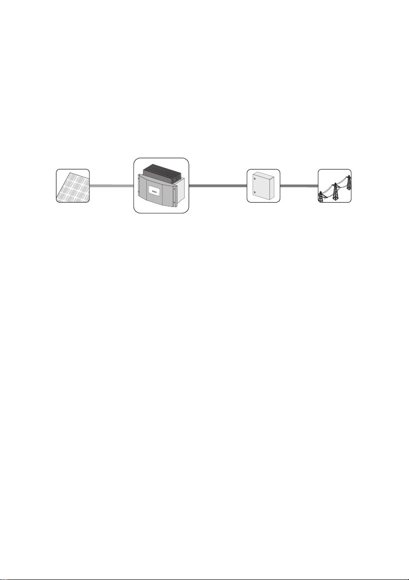
Public grid
PV modules
Sunny Boy
Distribution
2 Safety
2.1 Intended Use
The Sunny Boy is a PV inverter which converts the DC current of the PV array to AC current and feeds
it into the power distribution mains.
Principle of a PV Plant with this Sunny Boy
The Sunny Boy may only be operated with PV arrays (modules and cabling) of protection class II.
Do not connect any energy sources other than PV modules to the Sunny Boy.
When designing the PV plant, ensure that the values comply with the permitted operating range of all
components at all times. The free design program "Sunny Design" (www.SMA.de/en/SunnyDesign)
will assist you. The manufacturer of the PV modules must have approved the modules for use with this
Sunny Boy device . You must a lso en sure that a ll measure s recommended by the module manufacturer
regarding long-term maintenance of the module properties are taken (see also Technical Information
"Module Technology" in the download area of www.SMA.de/en).
Do not use the Sunny Boy for purposes other than those described here. Alternative uses,
modifications to the Sunny Boy or the installation of component parts not expressly recommended or
sold by SMA Solar Technology AG shall void any warranty claims and the operation permission.
Installation Manual SB25-30-IA-en-51 9
Page 10
Safety SMA Solar Technology AG
2.2 Safety Precautions
DANGER!
Danger to life due to high voltages in the inverter
• All work on the inverter may only be carried out by an electrically qualified person.
CAUTION!
Risk of burns due to hot enclosure parts
• Do not touch the enclosure during operation.
• Only touch the lid during operation.
WARNING!
Risk of electric shock when pulling out the DC connectors under load
If you disconnect the DC connectors from the inverter under load, an electric arc may
occur, leading to electric shock and burns.
• If the inverter is not equipped with an Electronic Solar Switch and the regulations
valid at the installation site require an external DC switch-disconnector, install an
external DC switch-disconnector.
• Switch off the AC miniature circuit-breaker and disconnect the inver ter on t he D C si de
before pulling out the DC connectors.
NOTICE!
Dust and water intrusion can damage the inverter.
If the inverter is equipped with an Electronic Solar Switch, it will only provide IP21 degree
of protection once the Electronic Solar Switch has been pulled out. The inverter is therefore
no longer protected against water and dust intrusion. In order to also maintain degree of
protection IP65 during temporary decommissioning, proceed as follows:
• Unlock and disconnect all DC connectors.
• Open all DC connectors and remove the cables.
• Close all DC inputs with the corresponding DC connectors and the supplied sealing
plugs.
• If an Electronic Solar Switch is installed, reattach the Electronic Solar Switch firmly.
10 SB25-30-IA-en-51 Installation Manual
Page 11
SMA Solar Technology AG Safety
NOTICE!
Damage to the inverter due to moisture and dust intrusion
If the Electronic Solar Switch is not plugged in or incorrectly plugged in during operation,
moisture and dust can penetrate the inverter.
If the Electronic Solar Switch is not correctly plugged in, this can cause contacts to wear in
the Electronic Solar Switch or the Electronic Solar Switch might fall down. This can result in
yield loss and damage to the Electronic Solar Switch.
Always plug in the Electronic Solar Switch as described in the following:
• Do not tighten the screw in the Electronic Solar Switch.
• Firmly plug in the Electronic Solar Switch until it is flush with the enclosure.
• Ensure that the maximum distance between the Electronic Solar Switch and the
enclosure is 1 mm.
PV array earthing
Comply with local regulations when earthing the modules and the PV array.
SMA Solar Technology AG recommends connecting the array frame and other electr ically
conductive surfaces so that there is continuous conduction and to earth them in order to
ensure maximum protection for installations and persons.
Installation Manual SB25-30-IA-en-51 11
Page 12
Safety SMA Solar Technology AG
2.3 Explanation of Symbols
This section gives an explanation of all the symbols found on the inverter and on the type label.
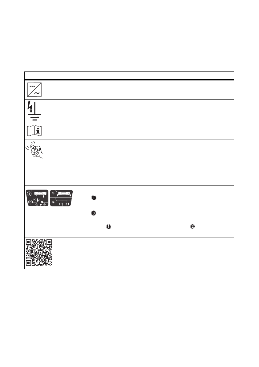
2.3.1 Symbols on the Inverter
Symbol Explanation
Operation display
Indicates the operating state of the inverter.
Ground fault or varistor defective
Read Section 9.3 "Red LED is Permanently Lit" (page55).
Error or fault
Read Section 9 "Troubleshooting" (page51).
You can operate the display by tapping on the enclosure lid:
• Tapping once: the backlight switches on or the display scrolls to the
next display message.
• Tapping twice in quick succession*: the inverter shows the display
messages from the startup phase again (see Section 6.2 "Display
Messages during the Startup Phase" (page38)).
DC switch-disconnector Electronic Solar Switch (ESS)**
• When the Electronic Solar Switch is plugged in, the electric DC
circuit is closed.
• To interrupt the electric DC circuit and disconnect the inverter
securely under load, you have to first pull out the Electronic Solar
Switch and then remove all DC connectors as described in
Section 7.2 "Opening the Inverter" (page44).
QR-Code
You will find information on the SMA bonus programme at
www.SMA-Bonus.com.
®
*** for SMA bonus program
* This function is valid from firmware version 4.00, not for SB 2500-IT/3000-IT
** Optional
*** QR-Code is a registered trademark of DENSO WAVE INCORPORATED.
12 SB25-30-IA-en-51 Installation Manual
Page 13
SMA Solar Technology AG Safety
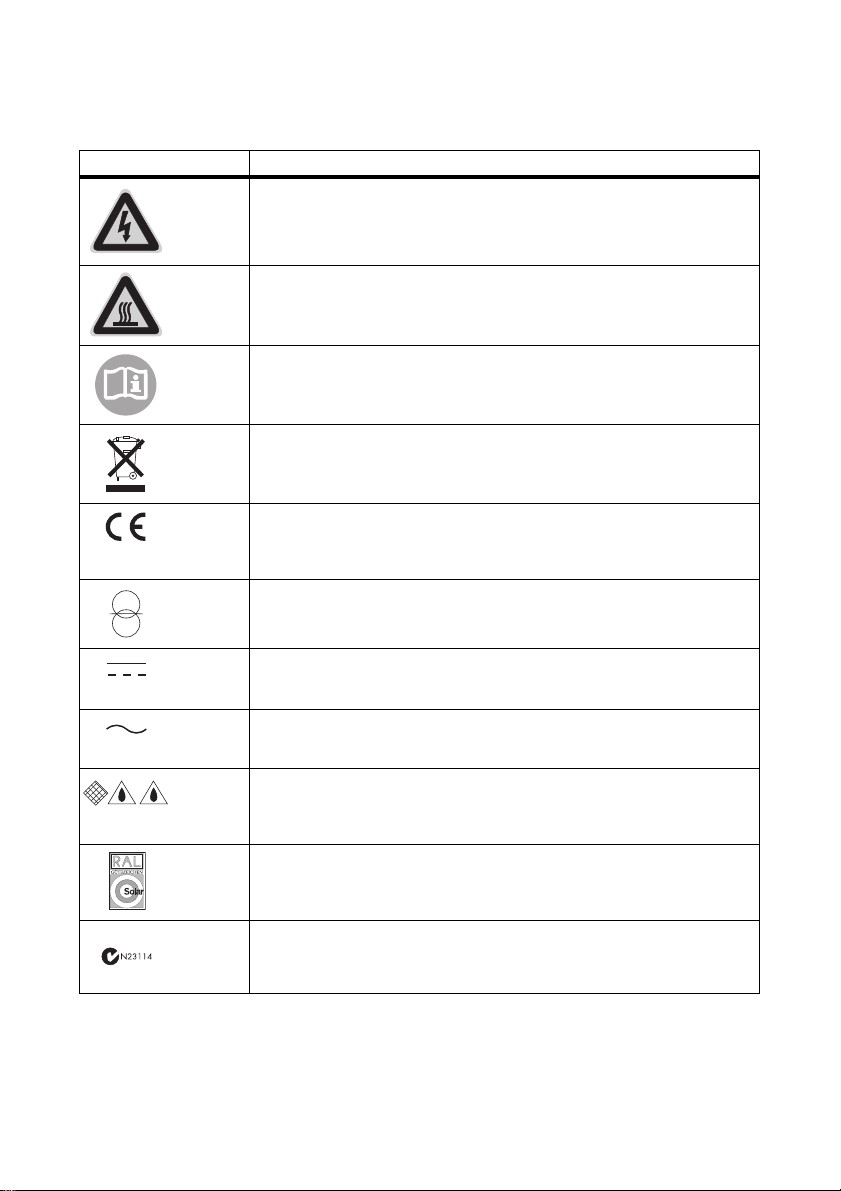
2.3.2 Symbols on the Type Label
Symbol Explanation
Beware of hazardous voltage.
The inverter operates at high voltages. All work on the inverter may only be
carried out by an electrically qualified person.
Beware of hot surface.
The inverter can become hot during operation. Avoid contact during
operation.
Observe all documentation that accompanies the inverter.
Th e in ver ter must not be d isp ose d of tog eth er w ith the h ous eho ld waste. For
more information on disposal, see Section 10.4 "Disposing of the Inverter"
(page61).
CE marking
The inverter complies with the requirements of the applicable EC
guidelines.
The inverter has a transformer
Direct current (DC)
Alternating current (AC)
Degree of protection IP65
The inverter is protected against dust intrusion and water jets from any
angle.
RAL quality mark for solar products
The inverter complies with the requirements of the German Institute for
Quality Assurance and Labeling.
Australian mark of conformity
Installation Manual SB25-30-IA-en-51 13
Page 14
Unpacking SMA Solar Technology AG
(
N
a
m
e
d
e
s
G
e
rä
t
e
s
)
:
B
it
te
f
ü
lle
n
S
ie
d
ie
f
o
lg
e
n
d
e
n
F
e
ld
e
r
a
u
s
:
(Name des Gerätes):
Bitte füllen Sie die folgenden Felder aus:
:
Ty
p
:
S
e
r
i
e
n
n
u
m
m
e
r
:
D
a
t
u
m
d
e
r
I
n
b
e
t
r
i
e
b
n
a
h
m
e
:
A
n
s
c
h
r
i
f
t
:
I
n
s
t
a
l
l
a
t
i
o
n
s
b
e
t
r
i
e
b
Typ:
Seriennummer:
Datum der Inbetriebnahme:
Anschrift:
Installationsbetrieb
Ty
p
:
S
e
r
i
e
n
n
u
m
m
e
r
:
D
a
t
u
m
d
e
r
I
n
b
e
t
r
i
e
b
n
a
h
m
e
:
A
n
s
c
h
r
i
f
t
:
I
n
s
t
a
l
l
a
t
i
o
n
s
b
e
t
r
i
e
b
Typ:
Seriennummer:
Datum der Inbetriebnahme:
Anschrift:
Installationsbetrieb
G
e
w
ä
h
r
le
i
s
tu
n
g
s
u
n
d
G
a
r
a
n
t
ie
b
e
d
in
g
u
n
g
e
n
Gewährleistungs- und Garantiebedingungen
F
GH
I
K
L
MN
E
+
+
+
_
_
_
3 Unpacking
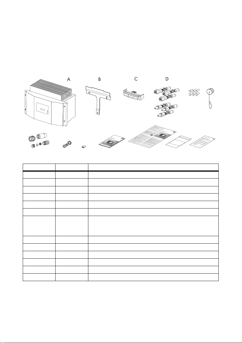
3.1 Scope of Delivery
Check the delivery for completeness and for any visible external damage. Contact your specialty
retailer if anything is damaged or missing.
Object Quantity Description
A 1Sunny Boy
B 1 Wall mounting bracket
C 1 Electronic Solar Switch (ESS)*
D 6 (2) DC connector (3 x positive, 3 x negative)**
E 6 (2) Sealing plug for DC connectors***
F 1 Protective cap for AC jack on inverter
G 1 AC connection socket: jack element, threaded sleeve,
PG13.5 pressure screw, PG13.5 sealing ring,
PG13.5 fastening case, PG16 cable gland
H 1 M6x12 cheese-head screw and conical spring washer
I 1Jumper
K 1 Installation manual
L 1 User manual
M 1 Document set with explanations and certificates
N 1 Supplementary sheet with inverter default settings
* Optional
** For inverters without ESS: 1 x positive, 1 x negative
*** For inverters without ESS: 2 sealing plugs
14 SB25-30-IA-en-51 Installation Manual
Page 15

SMA Solar Technology AG Unpacking
3.2 Identifying the Inverter
You can identify the inverter using the type label. The type label is on the right-hand side of the
enclosure.
The serial number (Serial No.) and the type (Type/Model) of the inverter, as well as device-specific
characteristics are specified on the type label.
Installation Manual SB25-30-IA-en-51 15
Page 16
Mounting SMA Solar Technology AG
4 Mounting
4.1 Safety
DANGER!
Danger to life due to fire or explosion
Despite careful construction, electrical devices can cause fires.
• Do not mount the inverter on flammable construction materials.
• Do not mount the inverter in areas where highly flammable materials are stored.
• Do not mount the inverter in a potentially explosive atmosphere.
CAUTION!
Risk of burns due to hot enclosure parts
• Mount the inverter in such a way that the enclosure cannot be touched inadvertently.
CAUTION!
Risk of injury due to the heavy weight of the inverter
• Take the inverter's weight of approx. 32 kg into account for mounting.
4.2 Selecting the Mounting Location
Consider the following requirements when selecting the mounting location:
• The mounting method and location must be suitable for the inverter's weight and dimensions
(see Section 11 "Technical Data" (page62)).
• Mount on a solid surface.
• The mounting location must at all times be clear and safely accessible without the use of
additional aids such as scaffolding or lifting platforms. Non-fulfillment of these criteria may
restrict servicing.
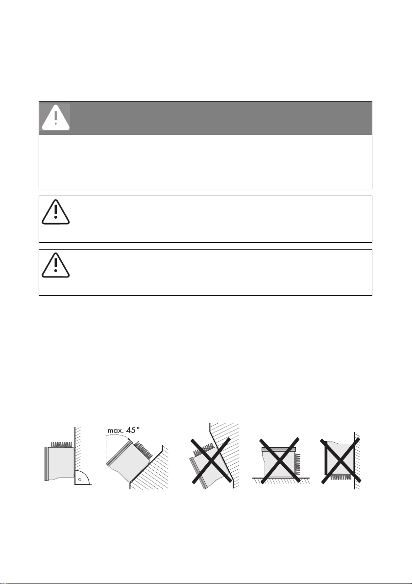
• Mount vertically or tilted backwards by max. 45°.
16 SB25-30-IA-en-51 Installation Manual
Page 17
SMA Solar Technology AG Mounting
• The connection area must point downward.
• Never mount the device with a forward tilt.
• Never mount the device with a sideways tilt.
• Do not mount horizontally.
• Install at eye level in order to allow operating states to be read at all times.
• To ensure optimal operation, the ambient temperature should be below 40°C.
• Do not expose the inverter to direct solar irradiation as this can cause excessive heating and
thus power reduction.
• I n a l ivi ng a rea, do n ot m oun t the uni t on pla sterboa rd w all s (o r si milar) i n or der to avoid aud ibl e
vibrations. When in use, the inverter emits noises which may be perceived as a nuisance in a
living area.
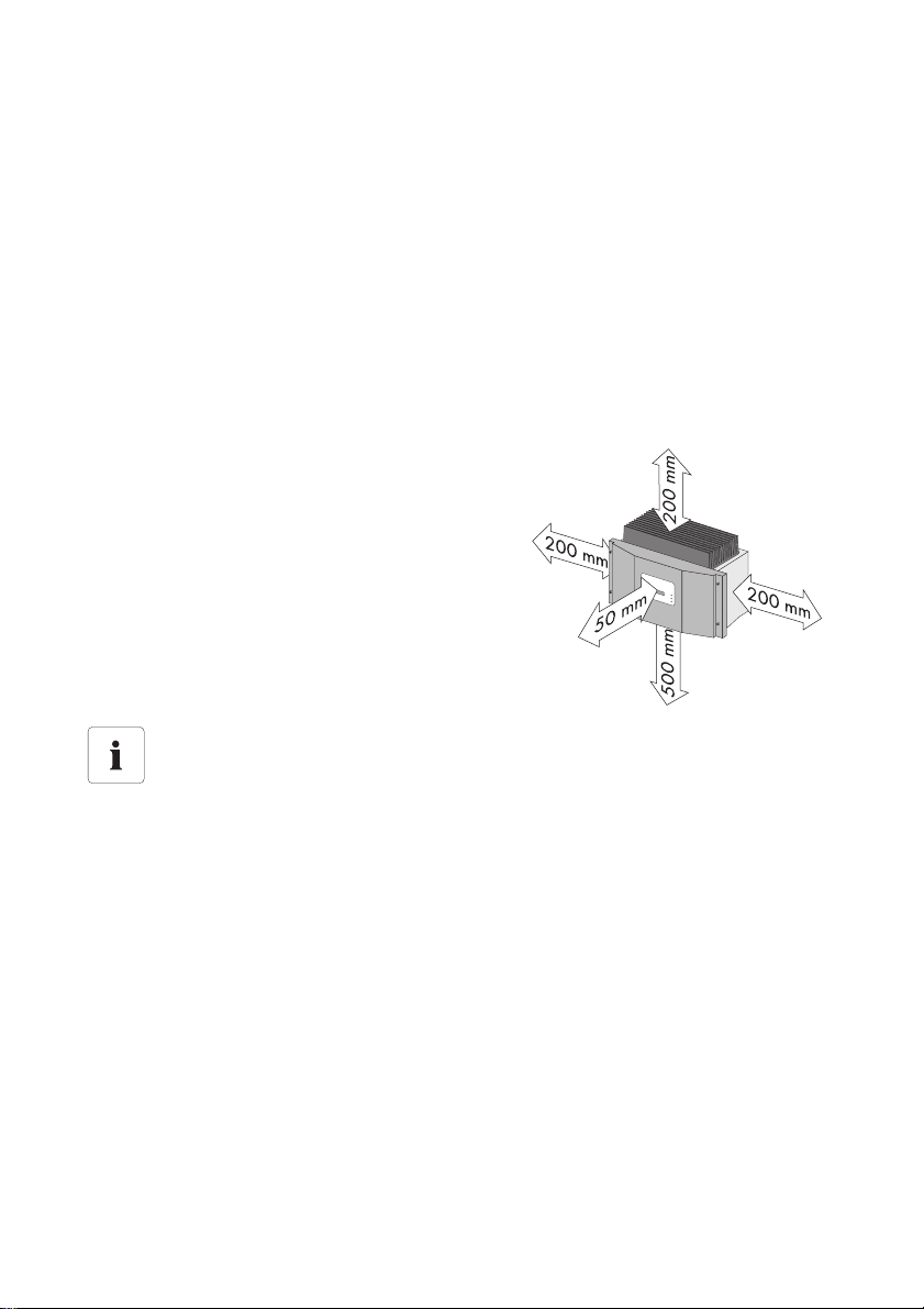
• Observe the minimum clearances to walls, other
inverters or objects as shown in the diagram in
order to ensure sufficient heat dissipation and
sufficient space for removing the Electronic Solar
Switch.
Multiple inverters installed in areas with high ambient temperatures
If necessary, increase the clearance spaces and make sure there is enough fresh-air supply
to ensure sufficient cooling of the inverters.
Installation Manual SB25-30-IA-en-51 17
Page 18
Mounting SMA Solar Technology AG
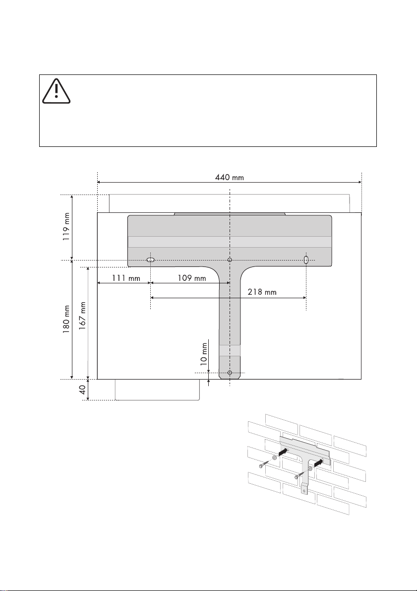
4.3 Mounting the Inverter with the Wall Mounting Bracket
CAUTION!
Risk of injury due to the heavy weight of the inverter
• Take the inverter's weight of approx. 32 kg into account for mounting.
• Use mounting material suitable for the surface when attaching the wall mounting
bracket.
1. Use the wall mounting bracket as a drilling template and mark the positions of the drill holes.
2. Attach the wall mounting bracket to the wall using
appropriate screws and washers.
18 SB25-30-IA-en-51 Installation Manual
Page 19
SMA Solar Technology AG Mounting
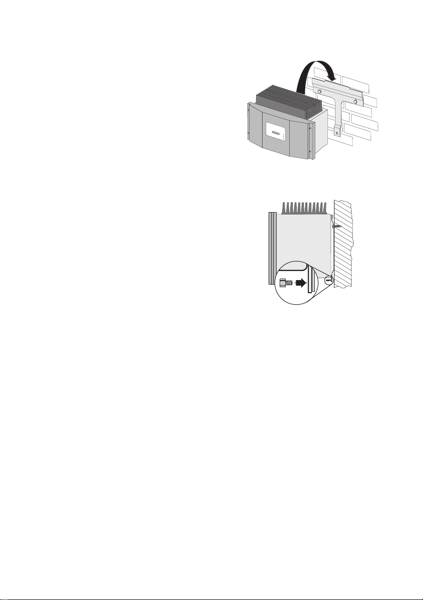
3. Mount the inverter with its upper anchorage
br ack et o n th e wa ll m oun tin g br ack et i n su ch a way
that it cannot slide out of the bracket sideways.
4. If a second protective conductor is required in the
country of installation, earth the inverter and fix it
se cur ely as d esc rib ed i n Se cti on 5 .2. 3 "Co nne cti ng
Additional Earthing" (page27).
5. If a second protective conductor is not required, fix
the inverter securely using the enclosed M6x12
screw.
6. Check to ensure that the inverter is securely in place.
☑The inverter is mounted to the wall.
Installation Manual SB25-30-IA-en-51 19
Page 20
Electrical Connection SMA Solar Technology AG
5 Electrical Connection
NOTICE!
Electrostatic discharges can damage the inverter.
Internal component parts of the inverter can be irreparably damaged by static electric
discharge.
• Earth yourself before touching a component part.
5.1 Overview of the Connection Area
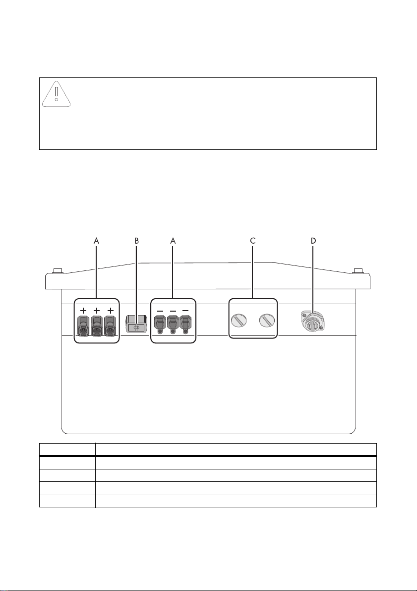
5.1.1 Exterior View
The following figure shows the assignment of the individual connection areas on the bottom of the
inverter.
Object Description
A DC connectors for connecting the PV strings*
B Jack for connecting the DC switch-disconnector Electronic Solar Switch (ESS)**
C Enclosure opening with filler-plugs for communication
D Jack for AC connection
* If you have ordered the inverter without ESS, the inverter is equipped with 1 negative and 1 positive DC connector.
** Optional
20 SB25-30-IA-en-51 Installation Manual
Page 21
SMA Solar Technology AG Electrical Connection
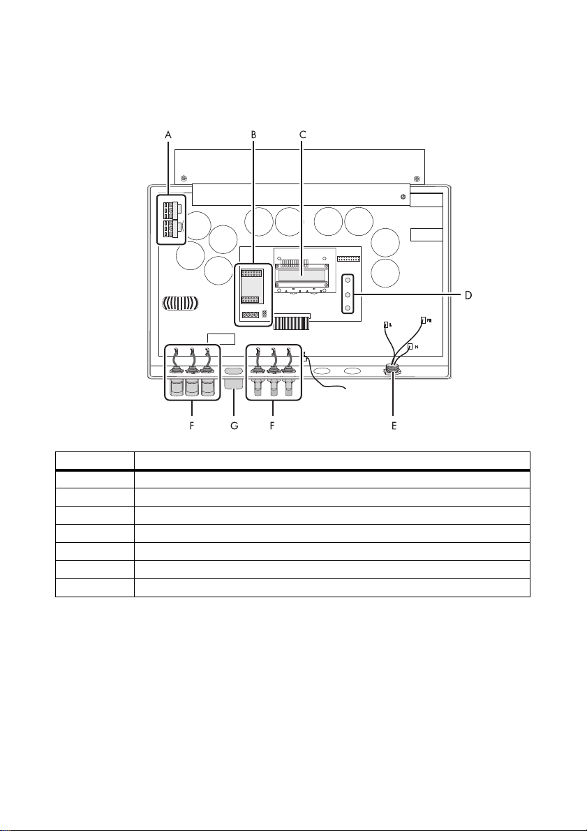
5.1.2 Interior View
The following figure shows the various components and connection areas of the open inverter.
Object Description
A Varistors
B Connection area and slots for optional communication via RS485
C Display
D Operating status LEDs
E Jack for AC connection
F DC connector*
G Jack for the Electronic Solar Switch (ESS)**
* If you have ordered the inverter without ESS, the inverter is equipped with 1 negative and 1 positive DC connector.
** Optional
Installation Manual SB25-30-IA-en-51 21
Page 22
Electrical Connection SMA Solar Technology AG
D
B
A
C
5.2 Connection to the Power Distribution Mains (AC)
5.2.1 Conditions for the AC Connection
Connection requirements of the network operator
Comply with the connection requirements of your network operator.
Cable dimensioning
Use Sunny Design version 2.0 or higher for dimensioning the conductor cross-sectional areas
(see Sunny Design programme at www.SMA.de/en).
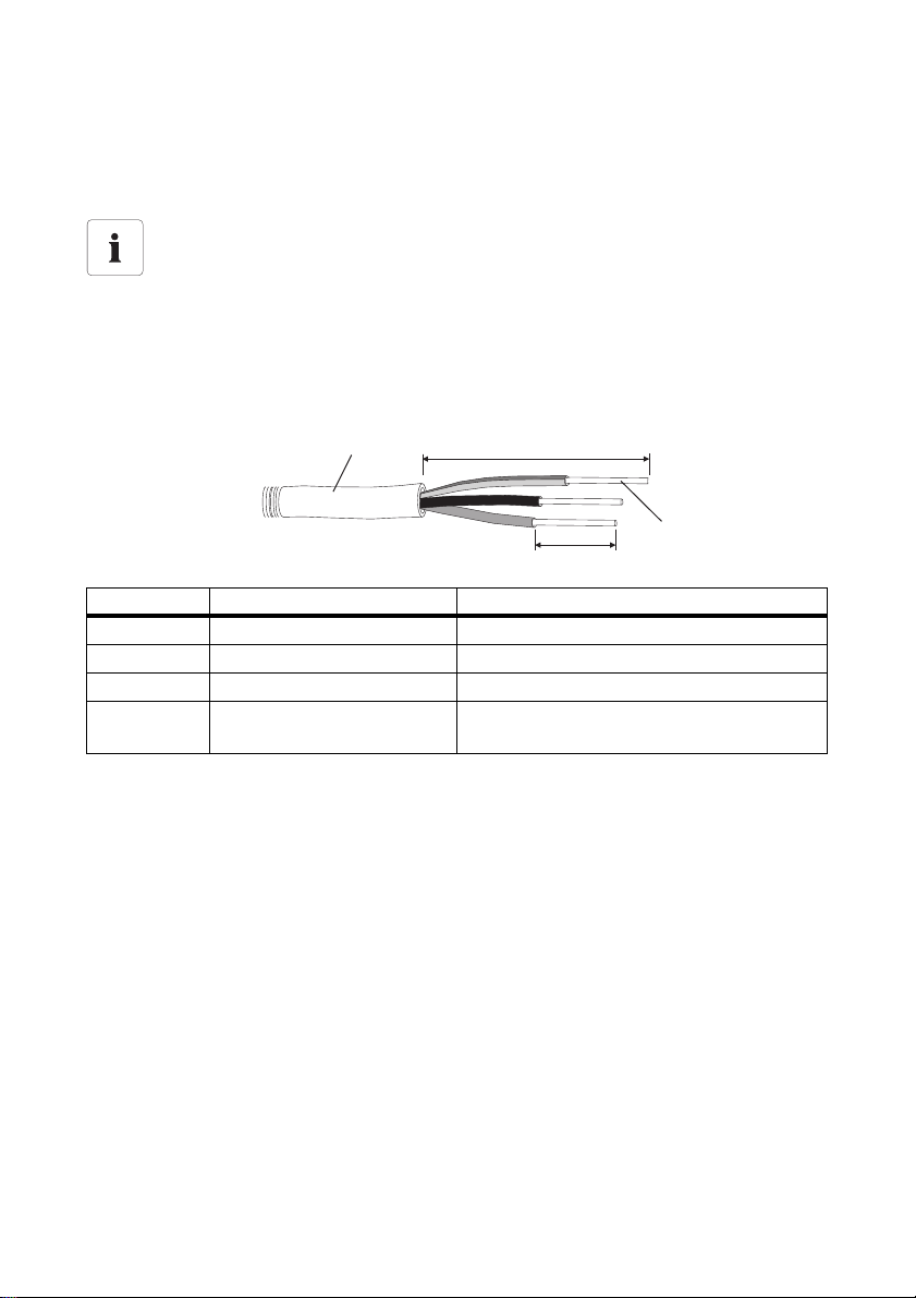
Cable requirements
Position Designation Value
A External diameter 9 mm … 17 mm
B Stripping length 30 mm
C Conductor cross-section Max. 2.5 mm²
D Length of insulation to be
stripped off
4mm…5mm
22 SB25-30-IA-en-51 Installation Manual
Page 23
SMA Solar Technology AG Electrical Connection
Load Disconnection Unit
You must install a separate miniature circuit-breaker for each inverter in order to ensure that the
inverter can be securely disconnected under load. The maximum permissible fuse protection can be
found in Section 11 "Technical Data" (page62).
Detailed information and examples for the rating of a miniature circuit-breaker can be found in the
Technical Information "Miniature Circuit-breaker" in the SMA Solar Technology AG download area
at www.SMA.de/en.
DANGER!
Danger to life due to fire
When more than 1 inverter is connected in parallel to the same miniature circuit-breaker,
the protective function of the miniature circuit-breaker is no longer guaranteed. It can result
in a cable fire or destruction of the inverter.
• Never connect several inverters to a single miniature circuit-breaker.
• Observe the maximum permissible fuse protection of the inverter when selecting the
miniature circuit-breaker.
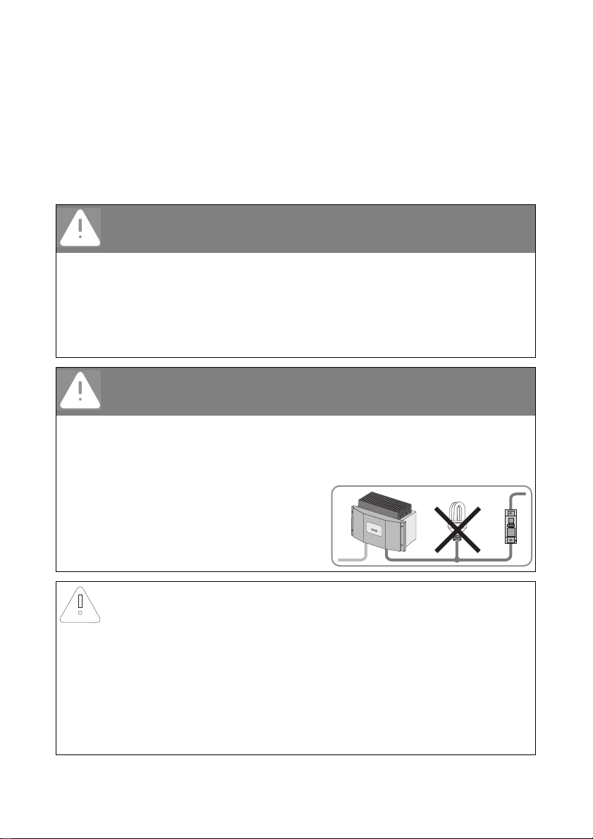
DANGER!
Danger to life due to fire
When a generator (inverter) and a load are connected to the same miniature circuitbreaker, the protective function of the miniature circuit-breaker is no longer guaranteed.
The currents from the inverter and the mains can accumulate to overcurrents that are not
detected by the miniature circuit-breaker.
• Never connect loads between the
inverter and the miniature circuitbreaker without protection.
• Always protect loads separately.
NOTICE!
Damage to the inverter by using screw type fuse elements as a load
disconnection unit
A screw type fuse element, e.g. DIAZED fuse or NEOZED fuse, is not a switch-disconnector,
and thus may not be used as a load disconnection unit. A screw type fuse element serves
as cable protection only.
When disconnecting under load using a screw type fuse element, the inverter can be
damaged.
• Use o nly a switc h-disconnecto r or a mi niatu re circuit-bre aker as a load discon necti on
unit.
Installation Manual SB25-30-IA-en-51 23
Page 24

Electrical Connection SMA Solar Technology AG
5.2.2 Connecting the Inverter to the Power Distribution Mains (AC)
Overview of the AC connection socket
Object Description
A Jack element
B Threaded sleeve
C PG13.5 sealing ring
D PG13.5 fastening case
E PG13.5 pressure screw (for a cable diameter between 9 mm … 13.5 mm)
F PG16 cable gland (for a cable diameter between 13.5 mm ... 17 mm)
Procedure
1. Choose an appropriate gland for the AC cable.
2. Check the line voltage and compare with "V
The exact operating range of the inverter is specified in the operating parameters. The
corresponding document can be found in the download area at www.SMA.de/en, in the
"Technical Description" category of the respective inverter.
3. Switch off the miniature circuit-breaker, ensure that the device cannot be unintentionally or
accidentally reconnected, and ensure that no voltage is present.
4. Strip approx. 30 mm from the AC cable.
5. Shorten L and N by 5 mm.
6. Strip 4 to 5 mm of insulation from the AC cable conductors.
7. Pass the pressure screw and/or cable gland and threaded sleeve over the AC cable.
24 SB25-30-IA-en-51 Installation Manual
" on the type label.
AC nom
Page 25

SMA Solar Technology AG Electrical Connection
Size used Procedure
PG13.5 • Push the sealing ring into the
fastening case.
• Slide the PG13.5 pressure
screw and the fastening case
including the sealing ring
over the AC cable.
• Slide the threaded sleeve
over the AC cable.
PG16 • Slide the PG16 cable gland
over the AC cable.
• Slide the threaded sleeve
over the AC cable.
8. Insert the protective conductor PE (green-yellow)
into the screw terminal with the earthing sign on the
jack element and tighten the screw.
9. Insert the neutral conductor N (blue) into screw
terminal 1 on the jack element and tighten the
screw.
10. Insert phase L (brown or black) into screw terminal 2
on the jack element and tighten the screw.
11. Leave screw terminal 3 on the jack element free.
12. Make sure the insulated conductors are securely
connected.
13. Screw the threaded sleeve onto the jack element.
Installation Manual SB25-30-IA-en-51 25
Page 26

Electrical Connection SMA Solar Technology AG
14. Tighten the pressure screw or cable gland onto the threaded sleeve.
Size used Procedure
PG13.5
The fastening case along with the sealing ring is pressed into the threaded
sleeve and can no longer be seen.
PG16 • Tighten the swivel nut of the
cable gland.
☑ AC connection socket has been screwed together.
15. If the AC connection socket is not immediately connected to the inverter, close the AC plug on
the inverter with the protective cap provided.
16. Insert the AC connection socket into the AC jack on
the inverter. Remove the protective cap
beforehand, if required.
17. Screw the threaded ring of the AC connection
socket tightly onto the AC jack on the inverter. The
threaded ring serves to seal and relieve strain on
the AC connection socket.
☑ The AC cable is connected to the inverter.
DANGER!
Danger to life due to high voltages in the inverter.
• Do not switch on the miniature circuit-breaker until the PV array has been connected
and the inverter is securely closed.
26 SB25-30-IA-en-51 Installation Manual
Page 27

SMA Solar Technology AG Electrical Connection
5.2.3 Connecting Additional Earthing
If a second protective conductor, additional earthing or equipotential bonding is required, you can
additionally earth the inverter on the enclosure.
Overview of the additional earthing
Object Description
A M6x12 cheese-head screw (included in the scope of delivery)
B Washer
C Terminal lug (M6) with protective conductor
D Conical spring washer (included in the scope of delivery)
E Metal bracket on the underside of the enclosure
F Wall mounting bracket of the inverter
Procedure
1. Align washer, terminal lug with protective
conductor and conical spring washer on the
cheese-head screw. The teeth of the conical spring
washer must be facing the metal bracket.
2. Insert the cheese-head screw into the metal bracket
on the underside of the enclosure and tighten it to
the wall mounting bracket. Tighten the cheese-head
screw to a torque of 6 Nm.
3. Make sure that the contact between the protective
conductor and the enclosure is in accordance with
the regulations valid for the country of installation.
Installation Manual SB25-30-IA-en-51 27
Page 28

Electrical Connection SMA Solar Technology AG
5.3 Setting the Display Language
You can set the language of the display using the switches at the bott om of the dis pla y as sembly i nsi de
the inverter.
Procedure
1. Open the inverter as described in Section 7.2 "Opening the Inverter" (page44).
2. Set the switches to the required language, as
shown below.
Language Switch S2 Switch S1
German B B
English B A
French A B
Spanish A A
The following switch settings apply for type SB 2500-IT/3000-IT inverters:
Language Switch S2 Switch S1
Italian B A
English A A
3. Close the inverter as described in Section 7.3 "Closing the Inverter" (page47).
☑ The display language is set.
5.4 PV Array Connection (DC)
5.4.1 Conditions for the DC Connection
Use of adaptors
Adaptors (Y plugs) must not be visible or freely accessible in the immediate surroundings
of the inverter.
• The electric DC circuit must not be interrupted by adaptors.
• Observe the procedure for disconnecting the inverter as described in Section 7.2
"Opening the Inverter" (page44).
• Requirements for the PV modules of the connected strings:
– Same type
– Same quantity
– Identical alignment
– Identical tilt
• T he c onn ect ing cab les of t he P V mo dul es m ust be e quipped wit h connectors. The DC connectors
for the DC connection are included in the delivery.
28 SB25-30-IA-en-51 Installation Manual
Page 29

SMA Solar Technology AG Electrical Connection
... ...
• The following limiting values at the DC input of the inverter must not be exceeded:
Inverter Maximum input voltage Maximum input current
SB 2500
SB 2500-IT
SB 3000
SB 3000-IT
DANGER!
Risk of lethal electric shock or fire
The maximum possible input current per string is limited by the connectors used. If the
connectors are overloaded, an electric arc may occur and there is a risk of fire.
• Ensure that the input current for each string does not exceed the maximum throughfault current of the connectors used.
600 V (DC) 12.0 A (DC)
600 V (DC) 12.0 A (DC)
5.4.2 Assembling the DC Connectors
For connection to the inverter, all connection cables of the PV modules must be equipped with the
DC connectors provided.
To assemble the DC connectors, proceed as follows. Ensure the connectors have the correct polarity.
The DC connectors have the symbols "+" and "‒".
Cable requirements:
• Use a PV1-F cable.
Procedure
1. Insert the stripped cable into the plug as far as
possible.
2. Press the clamping bracket down until it audibly
snaps into place.
Installation Manual SB25-30-IA-en-51 29
Page 30

Electrical Connection SMA Solar Technology AG
3. Ensure the cable is correctly in place.
Result Measure
☑ If the conductors are visible in the hollow
• Proceed to step 4.
cavity of the clamping bracket, the cable is
in the correct position.
☑ If the conductors are not visible in the
hollow cavity, the cable is not in the correct
position.
• Loosen the clamping bracket. For this
purpose, use a screwdriver with a blade
width of 3.5 mm.
• Remove the cable and start again from
step 1.
4. Push the cable gland toward the thread and fasten to a torque of 2 Nm.
☑ The DC connectors are assembled and can now be connected to the inverter as described in
Section 5.4.4 "Connecting the PV Array (DC)" (page32).
30 SB25-30-IA-en-51 Installation Manual
Page 31

SMA Solar Technology AG Electrical Connection
5.4.3 Opening the DC Connector
1. Unscrew the cable gland.
2. To release the plug, slot a screwdriver into the side
catch mechanism and lever out. For this purpose,
use a screwdriver with a blade width of 3.5 mm.
3. Carefully pull the DC connector apart.
4. Loosen the clamping bracket. For this purpose, use
a screwdriver with a blade width of 3.5 mm.
5. Remove the cable.
☑ The cable is removed from the DC connector.
Installation Manual SB25-30-IA-en-51 31
Page 32

Electrical Connection SMA Solar Technology AG
5.4.4 Connecting the PV Array (DC)
DANGER!
Danger to life due to high voltages in the inverter
• Before connecting the PV array, ensure that the miniature circuit-breaker is switched
off.
NOTICE!
Excessive voltages can destroy the measuring device.
• Only use measuring devices with a DC input voltage range up to at least 1 000 V.
1. Disconnect the miniature circuit-breaker and secure against reconnection.
2. If an external DC switch-disconnector is present, disconnect the external DC switchdisconnector.
3. If an Electronic Solar Switch is installed, pull the
Electronic Solar Switch downwards, slightly
towards the wall.
4. Check the connection cables of the PV modules for
correct polarity and make sure that the maximum
input voltage of the inverter is not exceeded.
At an ambient temperature above 10°C, the opencircuit voltage of the PV modules must not be more
than 90% of the maximum inverter input voltage.
Ot herwise , ch eck the p lan t desig n an d th e PV mod ule
circuitry. If this is not done, the maximum inverter
input voltage can be exceeded at low ambient
temperatures.
32 SB25-30-IA-en-51 Installation Manual
Page 33

SMA Solar Technology AG Electrical Connection
NOTICE!
Exceeding the maximum input voltage can destroy the inverter.
If the voltage of the PV modules exceeds the maximum input voltage of the inverter, it can
be destroyed by the overvoltage.
This will void all warranty claims.
• Do not connect strings with an open-circuit voltage greater than the maximum input
voltage of the inverter.
• Check the plant design.
5. Check the strings for ground faults as described in Section 9.3.1 "Checking the PV Array for
Earth Faults" (page56).
DANGER!
Risk of lethal electric shock.
• Do not connect strings with ground faults.
•First, rectify the earth fault in the respective string.
6. Check the DC connectors for correct polarity and connect them.
To unlock the DC connectors, see Section 7.2 "Opening the Inverter" (page44).
Installation Manual SB25-30-IA-en-51 33
Page 34

Electrical Connection SMA Solar Technology AG
+
1
2
+
+
7. In order to seal the inverter, all the DC inputs that are not required have to be closed with DC
connectors and sealing plugs:
Sealing plugs
•Do NOT insert the sealing plugs DIRECTLY into the DC inputs on the inverter.
– For unused DC connectors, push down the
clamping bracket and push the cable gland
toward the thread.
– Insert the sealing plug into the DC connector.
– Tighten the DC connector (torque: 2 Nm).
– Insert the DC connectors with sealing plugs into
the corresponding DC inputs on the inverter.
☑ The DC connectors click audibly into position.
8. Ensure that all DC connectors are securely in place.
34 SB25-30-IA-en-51 Installation Manual
Page 35

SMA Solar Technology AG Electrical Connection
9. If an Electronic Solar Switch is installed, check the
Electronic Solar Switch for wear, as described in
Section 8.2 "Checking the Electronic Solar Switch
for Wear" (page49), and reattach it firmly.
NOTICE!
Damage to the inverter due to moisture and dust intrusion
If the Electronic Solar Switch is not plugged in or incorrectly plugged in during operation,
moisture and dust can penetrate the inverter.
If the Electronic Solar Switch is not correctly plugged in, this can cause contacts to wear in
the Electronic Solar Switch or the Electronic Solar Switch might fall down. This can result in
yield loss and damage to the Electronic Solar Switch.
Always plug in the Electronic Solar Switch as described in the following:
• Do not tighten the screw in the Electronic Solar Switch.
• Firmly plug in the Electronic Solar Switch until it is flush with the enclosure.
• Ensure that the maximum distance between the Electronic Solar Switch and the
enclosure is 1 mm.
☑ The PV array is connected.
5.5 Communication
The inverter is equipped with a slot for communication interfaces in order to communicate with special
data capture devices (e.g., Sunny WebBox) or a PC with corresponding software
(e.g. Sunny Data Control or Sunny Explorer).
Refer to the communication interface manual for a detailed wiring diagram and a mounting
description.
The inverter's active power can be limited externally using the Power Reducer Box from
SMA Solar Technology AG. You will find detailed information on active power limitation in the
Technical Description "Operating Parameters" at www.SMA.de/en.
Installation Manual SB25-30-IA-en-51 35
Page 36

Electrical Connection SMA Solar Technology AG
5.6 Setting the Mains and Country Parameters
Changing mains-relevant and country parameters
To change mains-relevant parameters, you need a personal access code – the so-called
SMA Grid Guard code. The application form for the personal access code is available in
the download area at www.SMA.de/en, in the "Certificate" category of the respective
inverter.
Ensure that you discuss the changes to these parameters with your network operator.
A detailed description of the operating parameters for the inverter is available in the download area
at www.SMA.de/en in the category "Technical Description" of the respective inverter.
5.6.1 Setting the Installation Country
Using the "Default" parameter, you can set the installation country and/or the mains connection
standard valid for the country via a communication device (e.g., Sunny WebBox) or a PC with
corresponding software (e.g., Sunny Data Control or Sunny Explorer). This, however, is only required
if the inverter was originally ordered for another country. You can see the standard to which the
inverter was set upon delivery on the type label and on the included supplementary sheet with the
default settings.
5.6.2 Setting Stand-alone Mains Operation
To operate the inverter in a stand-alone mains system with Sunny Island, you must set the "Default"
parameter to stand-alone mains ("OFF-Grid") operation.
You have several possibilities to set the inverter to stand-alone mains operation:
• Setting via Sunny WebBox
or
• Setting via Sunny Data Control or Sunny Explorer
DANGER!
Danger to life due to high voltages in the event of outage of the
power distribution mains
If you set the inverter to stand-alone mains operation, it does not fulfill any country-specific
standards and guidelines. Therefore, in the event of power distribution mains outage, there
is a danger of backfeed.
• Never operate the inverter directly on the power distribution mains when set to
stand-alone mains operation.
36 SB25-30-IA-en-51 Installation Manual
Page 37

SMA Solar Technology AG Commissioning
6 Commissioning
6.1 Commissioning the Inverter
1. Check the following requirements before commissioning:
– The inverter is securely in place.
– Correct connection of the AC cable (mains)
– Complete connection of all DC cables (PV strings)
– Unused DC inputs are closed using the corresponding DC connectors and sealing plugs
– The enclosure lid is securely screwed in place.
– External DC switch-disconnecto r additionally connected if Electronic Solar Switch available,
the Electronic Solar Switch (ESS) is firmly in place
– The miniature circuit-breaker is correctly laid out
2. Switch on the miniature circuit-breaker.
☑ All three LEDs are lit or flashing: the startup phase is starting.
☑ Green LED is lit: commissioning was successful.
or
☑ Green LED flashes in case of insufficient irradiation: mains connection conditions have not
yet been reached. Wait for sufficient irradiation.
or
☑ The red or yellow LED is lit or flashing: a fault has occurred. Proceed to step 3.
A Green LED Operation
B Red LED Earth fault or varistor defective
C Yellow LED Fault
Self-test in accordance with DK 5940, Ed. 2.2 during initial start-up
(applies to Italy only)
The Italian DK 5940 standard prescribes that an inverter can only operate on the power
distribution mains after the disconnection times for overvoltage, undervoltage, minimum
frequency and maximum frequency have been checked.
Start the self-test as described in Section 6.3 "Self-test in Accordance with DK 5940, Ed.
2.2 (Applies to Italy Only)" (page39). The test takes approx. 8minutes.
3. Read Section 9 "Troubleshooting" (page51) and if necessary, eliminate the error or fault.
Installation Manual SB25-30-IA-en-51 37
Page 38

Commissioning SMA Solar Technology AG
SB xxx
Wrxxx
6.2 Display Messages during the Startup Phase
• After commissioning, the inverter displays the
device type in the startup phase.
• After 5 seconds or when you tap on the enclosure
lid again, the firmware version of the internal
processors is displayed by the inverter.
• After a further 5 seconds or when you tap again,
th e co nfi gur ed c oun try stan dar d is dis pla yed by t he
inverter (example: "VDE-AR-N4105").
Show the display messages again (valid from firmware version 4.00)
If you want to view the display messages of the startup phase again while in normal
operation, double tap on the enclosure lid.
38 SB25-30-IA-en-51 Installation Manual
Page 39

SMA Solar Technology AG Commissioning
6.3 Self-test in Accordance with DK 5940, Ed. 2.2 (Applies to Italy Only)
6.3.1 Starting the Self-test by Tapping
You can start testing the disconnection times by tapping on the enclosure lid. A prerequisite here is
that the rotary switch for language settings on the inverter has been set to Italy (IT/DK5940) or
"trimmed". Proceed as follows for checking the disconnection times:
1. Connect the PV array to the inverter. The inverter can only initialise if the PV array produces
enough power. It is therefore not possible to test the disconnection times at night.
2. Connect the inverter on the AC side. For this, you have to establish the AC connection
(AC pl ug or direct con nection) a nd/or swit ch on the mi niatur e circuit-breaker of the mains cable
(fuse or miniature circuit-breaker).
3. The inverter is now in the initialisation phase, i.e. all three LEDs are lit at the same time.
Start the self-test immediately after all three LEDs have gone out by tapping on the display of
the inverter.
4. The question of whether you would like to start the
test sequence appears in the display. Tap on the
display again within 30 seconds to confirm the
question.
Once you have started the test sequence, the inverter checks the disconnection times for overvoltage,
undervoltage, maximum frequency and minimum frequency one after the other. During the tests, the
inverter shows the values in the display which are described in Section 6.3.2 "Completion of the Selftest" (page39).
6.3.2 Completion of the Self-test
Note down the values which are displayed during the self-test. These values must be entered into a
test report. The test results of the individual tests are displayed three times, one after the other. The
respec-tive display message is displayed for 10 seconds.
The self-test changes the upper and lower disconnection thresholds for each protective function on a
linear basis with a modification of 0.05 Hz/s and 0.05 Vn/s for the frequency and voltage monitoring. As soon as the actual measured value is outside the permissible range (modified disconnection
threshold), the inverter disconnects itself from the mains. In this way, the inverter determines the reaction time and checks itself.
Installation Manual SB25-30-IA-en-51 39
Page 40

Commissioning SMA Solar Technology AG
Overvoltage Test
The inverter begins with the overvoltage test. During the
test sequence, the voltage limit applied is shown in the
display of the inverter.
The voltage limit is reduced successively until the
disconnection threshold is reached and the inverter
disconnects from the mains.
Once the inverter has disconnected from the mains, the display successively shows the following
values one after the other:
•Disconnection value,
•Calibration value,
•Reaction time,
• Current line voltage.
40 SB25-30-IA-en-51 Installation Manual
Page 41

SMA Solar Technology AG Commissioning
Undervoltage Test
After the overvoltage test, the inverter performs the
undervoltage test. During the test sequence, the current
calibration value of the voltage limit applied is shown in
the display of the inverter.
The voltage limit is increased successively until the
disconnection threshold is reached and the inverter
disconnects from the mains.
Once the inverter has disconnected from the mains, the display successively shows the following
values one after the other:
•Disconnection value,
•Calibration value,
•Reaction time,
• Current line voltage.
Installation Manual SB25-30-IA-en-51 41
Page 42

Commissioning SMA Solar Technology AG
Maximum Frequency
In a third step, the inverter tests the maximum frequency.
During the test sequence, the frequency limit applied is
shown in the display of the inverter.
The frequency limit is reduced successively until the
disconnection threshold is reached and the inverter
disconnects from the mains.
Once the inverter has disconnected from the mains, the display successively shows the following
values one after the other:
•Disconnection value,
•Calibration value,
•Reaction time,
• Current power frequency.
42 SB25-30-IA-en-51 Installation Manual
Page 43

SMA Solar Technology AG Commissioning
Minimum Frequency
In the last step, the inverter tests the minimum frequency.
During the test sequence, the frequency limit applied is
shown in the display of the inverter.
The frequency limit is increased successively until the
disconnection threshold is reached and the inverter
disconnects from the mains.
Once the inverter has disconnected from the mains, the display successively shows the following
values one after the other:
•Disconnection value,
•Calibration value,
•Reaction time,
• Current power frequency.
Once the inverter has carried out the four tests, it switches to "MPP operation (MPP)" mode. The
original calibration values are then re-set and the inverter automatically connects to the mains. If you
would like to carry out the test again, you must disconnect the inverter, i.e. disconnect it on the AC
and DC sides and then later recommission it. You can then restart the self-test as described in
Section 6.3.1 "Starting the Self-test by Tapping" (page39). The inverter starts again the test sequence
as described in Section 6.3.2 "Completion of the Self-test" (page39).
Installation Manual SB25-30-IA-en-51 43
Page 44

Opening and Closing SMA Solar Technology AG
7 Opening and Closing
7.1 Safety
DANGER!
Risk of lethal electric shock
Before opening the inverter, observe the following:
• Ensure that no voltage is present on the AC side.
• Ensure that neither voltage nor current is present on the DC side.
NOTICE!
Electrostatic discharges can damage the inverter.
The internal component parts of the inverter can be irreparably damaged by electrostatic
discharge.
• Earth yourself before touching a component part.
7.2 Opening the Inverter
1. Disconnect the miniature circuit-breaker and secure against reconnection.
2. If an external DC switch-disconnector is present, disconnect the external DC switchdisconnector.
3. If an Electronic Solar Switch is installed, pull the
Electronic Solar Switch downwards, slightly
towards the wall.
4. Using a current probe, ensure that no current is
present at any of the DC cables.
☑ If current is present, check the installation.
44 SB25-30-IA-en-51 Installation Manual
Page 45

SMA Solar Technology AG Opening and Closing
5. Unlock and disconnect all DC connectors. To do
this, insert the screwdriver into one of the side slits
(blade width: 3.5 mm) and pull the DC connectors
st rai ght dow n. D o NOT pul l ON T HE C ABL E wh ile
doing this.
☑ All DC connectors are disconnected from the
inverter. The inverter is completely disconnected
from the PV array.
6. Pull out the AC plug.
7. Check whether all LEDs and the display have gone out.
DANGER!
Danger to life due to high voltages in the inverter
The capacitors in the inverter require 15 minutes to discharge.
• Wait 15 minutes before opening the inverter.
Installation Manual SB25-30-IA-en-51 45
Page 46

Opening and Closing SMA Solar Technology AG
8. Ens ure tha t no vol tag e is pre sen t at the DC p lug s on
the inverter.
☑If voltage is present, check the installation.
9. Remove all screws from the enclosure lid and pull
the lid forward smoothly.
10. Remove the protective conductor (PE) connection
from the lid by loosening the PE connection lock on
the lid.
☑ The inverter is open and no voltage is present.
46 SB25-30-IA-en-51 Installation Manual
Page 47

SMA Solar Technology AG Opening and Closing
7.3 Closing the Inverter
1. Establish the protective conductor (PE) connection to the enclosure lid.
2. Attach the enclosure lid of the inverter by evenly
tightening the four lid screws.
3. Check the DC connectors for correct polarity and connect them.
To unlock the DC connectors, see Section 7.2 "Opening the Inverter" (page44).
4. Close all the DC inputs that are not needed as described in Section 5.4.4 "Connecting the PV
Array (DC)" (page32) to seal the inverter.
5. Attach the AC plug.
6. If an external DC switch-disconnector is available, connect the external DC switch-disconnector.
Installation Manual SB25-30-IA-en-51 47
Page 48

Opening and Closing SMA Solar Technology AG
7. If an Electronic Solar Switch is installed, check the
Electronic Solar Switch for wear, as described in
Section 8.2 "Checking the Electronic Solar Switch
for Wear" (page49), and reattach it firmly.
NOTICE!
Damage to the inverter due to moisture and dust intrusion
If the Electronic Solar Switch is not plugged in or incorrectly plugged in during operation,
moisture and dust can penetrate the inverter.
If the Electronic Solar Switch is not correctly plugged in, this can cause contacts to wear in
the Electronic Solar Switch or the Electronic Solar Switch might fall down. This can result in
yield loss and damage to the Electronic Solar Switch.
Always plug in the Electronic Solar Switch as described in the following:
• Do not tighten the screw in the Electronic Solar Switch.
• Firmly plug in the Electronic Solar Switch until it is flush with the enclosure.
• Ensure that the maximum distance between the Electronic Solar Switch and the
enclosure is 1 mm.
8. Switch on the miniature circuit-breaker.
9. Check whether the display and the LEDs indicate a
normal operating state
(see Section 6 "Commissioning" (page37)).
☑ The inverter is closed and in operation.
48 SB25-30-IA-en-51 Installation Manual
Page 49

SMA Solar Technology AG Maintenance and Cleaning
A
B
8 Maintenance and Cleaning
Impurities such as dust or airborne pollen can cause a buildup of heat that can lead to yield losses.
Also check the inverter and the cables for visible external damage. Repair, if necessary.
8.1 Cleaning the Inverter
If the inverter is dirty, clean the enclosure lid, the display and the LEDs with clear water and a cloth
only.
Also check the inverter and the cables for visible external damage. Repair, if necessary.
8.2 Checking the Electronic Solar Switch for Wear
Check the Electronic Solar Switch for wear before plugging it in. Depending on the shape of the
Electronic Solar Switch, you can estimate the wear on either the metal tongues (shape A) or on the
plastic (shape B).
Result Measure
☑ The metal tongues in the
Electronic Solar Switch are undamaged
and not discoloured (A).
1. Securely attach the Electronic Solar Switch
handle.
2. Commission the inverter as described in
Section 6 "Commissioning" (page37).
or
☑ The plastic in the Electronic Solar Switch is
undamaged (B).
Installation Manual SB25-30-IA-en-51 49
Page 50

Maintenance and Cleaning SMA Solar Technology AG
A
B
Result Measure
☑ The metal tongues in the
Electronic Solar Switch have a brown
discolouration or are burned through (A).
Th e El ectroni c So lar Swi tch can no l onger re liably
disconnect the DC side.
1. Replace the Electronic Solar Switch handle
before attaching it again (for the order
number, see Section 12 "Accessories"
(page70)).
2. Recommission the inverter as described in
Section 6 "Commissioning" (page37).
or
☑The plastic in the Electronic Solar Switch
shows thermal deformation (B).
50 SB25-30-IA-en-51 Installation Manual
Page 51

SMA Solar Technology AG Troubleshooting
9 Troubleshooting
If the inverter displays other blink codes or error messages than those described below, contact the
SMA Service Line.
You will also find a description of display messages during operation, status messages and
measurement channels in the user manual provided.
Do not perform any repairs that are not described here and take advantage of the 24-hour
replacement service (inverter ready for shipping and handed over to a freight-forwarding company
within 24 hours) and the SMA Solar Technology AG repair service instead.
9.1 Blink Codes
Green Red Yellow Status
Flashing Flashing Flashing OK (startup phase)
Is permanently lit Is not lit Is not lit OK (feed-in operation)
Is permanently lit Is not lit Earth fault or varistor defective
Is permanently lit OK (initialisation)
Flashing quickly
(3 x per second)
Flashing slowly
(1 x per second)
Goes out briefly
(approx. 1 x per second)
Is not lit Is not lit Is not lit At night: OK
Is not lit Is not lit OK (stop)
Is permanently lit Is not lit Earth fault or varistor defective
Is not lit Is not lit OK
(waiting, mains monitoring)
Is permanently lit Is not lit Earth fault or varistor defective
Is not lit Is not lit OK (derating)
Is permanently lit Is not lit Earth fault or varistor defective
(overnight shutdown)
During the day:
Electronic Solar Switch is not
attached
Is lit/flashing Fault
Is permanently lit Is not lit Earth fault or varistor defective
Is lit/fl ashing E arth fault or var isto r def ectiv e
and fault
Installation Manual SB25-30-IA-en-51 51
Page 52

Troubleshooting SMA Solar Technology AG
9.2 Error Messages
When a fault occurs, the inverter generates a message which depends on the operating mode and
the type of the fault detected.
Message Description and corrective measure
!PV-Overvoltage!
!DISCONNECT DC!
ACVtgRPro The 10-minute average line voltage is no longer within the permissible
Bfr-Srr Internal measurement comparison fault or hardware defect
Overvoltage at DC input
Overvoltage can destroy the inverter.
Corrective measures
Disconnect the inverter from the mains immediately.
1. Disconnect the miniature circuit-breaker.
2. If an external DC switch-disconnector is available, disconnect it.
3. If an Electronic Solar Switch is installed, remove it.
4. Remove all DC connectors.
5. Check the DC voltage:
– If the DC voltage is above the maximum input voltage, check the
plant design or contact the PV array installer.
– If the DC voltage is below the maximum input voltage,
reconnect the inverter to the PV array as described in
Section 5.4 "PV Array Connection (DC)" (page28).
If the message occurs again, disconnect the inverter again and contact
the SMA Service Line (see Section 13 "Contact" (page71)).
range. This can be caused by either of the following:
• The line voltage at the termination point is too high.
• The mains impedance at the termination point is too high.
The inverter disconnects from the mains to assure compliance with the
power quality.
Corrective measures
Check the line voltage at the termination point of the inverter:
• If, due to the local mains conditions, the line voltage is 253 V or
more, ask the network operator whether the voltage at the feed-in
po int ca n be adjuste d, or wh eth er t hey woul d agree t o an alte ration
of the limiting value of parameter "ACVtgRPro" for power quality
monitoring.
• If the line voltage is continually within the tolerance range and this
error message is still displayed, contact the SMA Service Line.
Corrective measures
• If this fault occurs frequently, contact the SMA Service Line.
52 SB25-30-IA-en-51 Installation Manual
Page 53

SMA Solar Technology AG Troubleshooting
Message Description and corrective measure
EEPROM Transition fault while data is being written or read from EEPROM. The
data is not relevant for safe operation.
This fault has no effect on the performance of the inverter.
EEPROM dBh EEPROM data is defective, the device has switched off because the loss
of data has disabled important functions of the inverter.
Corrective measures
• Contact the SMA Service Line.
EeRestore One of the duplicate records in the EEPROM is defective and has been
reconstructed without loss of data.
• This error message only serves to inform you and has no effect on
the performance of the inverter.
Fac-Bfr
Fac-Srr
FacFast
The power frequency is no longer within the permissible range
("Bfr" or "Srr" is an internal message of no relevance for the user).
The inverter disconnects itself from the power distribution mains for safety
reasons.
Corrective measures
• Check the mains connection and contact the network operator if
necessary.
• If the power frequency is within the tolerable range, but "Fac-Bfr",
"Fac-Srr"or "FacFast" faults are still displayed, contact the
SMA Service Line.
Imax Overc urrent on t he AC s ide. This message is di splaye d if th e current in the
AC mains is higher than specified.
Corrective measures
• Check the plant design and mains conditions.
K1-Close
K1-Open
Error during relay test
Corrective measures
• If this fault frequently occurs or occurs several times consecutively,
contact the SMA Service Line.
MSD-Fac
MSD-Vac
MSD-Timeout
Internal measurement comparison fault or hardware defect.
Corrective measures
• If this fault occurs frequently, contact the SMA Service Line.
offset The "offset" operating state is a normal operating state that occurs prior
to mains monitoring. If "offset" is displayed as an error, there is a fault in
the data logging.
Corrective measures
• If this fault occurs frequently, contact the SMA Service Line.
Installation Manual SB25-30-IA-en-51 53
Page 54

Troubleshooting SMA Solar Technology AG
Message Description and corrective measure
Earthfault The electrical insulation between the PV plant and earth is defective.
The resistance between the DC plus and/or DC minus connection and
earth is outside the defined limit range.
Corrective measures
• Check the insulation of the PV plant.
• Check the installation for earth faults as described in Section 9.3.1
"Checking the PV Array for Earth Faults" (page56).
ROM The inverter's firmware is faulty.
Corrective measures
• If this fault occurs frequently, contact the SMA Service Line.
Shutdown Temporary inverter fault.
Corrective measures
• Contact the SMA Service Line.
Vac-Bfr
Vac-Srr
The line voltage is no longer within the permissible range
("Bfr" or "Srr" is an internal message of no relevance for the user).
This fault can be caused by any of the following conditions:
• Mains disconnected (miniature circuit-breaker, fuse)
• AC cable is interrupted
• AC cable is highly resistive
The inverter disconnects itself from the power distribution mains for safety
reasons.
Corrective measures
• Check the line voltage and mains connection on the inverter.
• If the line voltage lies outside the acceptable range because of
local mains conditions, ask the network operator if the voltages can
be adjusted at the feed-in point or if they agree to changes in the
values of the monitored operating limits
(operating parameters: Vac-Min and Vac-Max).
• If the line voltage lies within the tolerance range, yet "Vac-Bfr" or
"Vac-Srr" faults are still displayed, contact the SMA Service Line.
54 SB25-30-IA-en-51 Installation Manual
Page 55

SMA Solar Technology AG Troubleshooting
Message Description and corrective measure
VpvMax
Vpv-Max
Overvoltage at DC input. The inverter may be damaged.
Corrective measures
Immediately disconnect the inverter from the mains.
1. Disconnect the miniature circuit-breaker.
2. If an external DC switch-disconnector is available, disconnect it.
3. If an Electronic Solar Switch is installed, remove it.
4. Remove all DC connectors.
5. Check the DC voltage:
– If the DC voltage is above the maximum input voltage, check the
plant design or contact the PV array installer.
– If the DC voltage is below the maximum input voltage,
reconnect the inverter to the PV array as described in
Section 5.4 "PV Array Connection (DC)" (page28).
If the message occurs again, disconnect the inverter again and contact
the SMA Service Line (see Section 13 "Contact" (page71)).
Watchdog
Watchdog Srr
Internal program run fault
Corrective measures
• If this fault occurs frequently, contact the SMA Service Line.
9.3 Red LED is Permanently Lit
If the red status display LED is permanently lit during operation, there is an earth fault in the PV array,
at least one of the varistors for overvoltage protection is defective or there is an insulation fault.
Procedure
1. Check for earth faults in the PV array as described in Section 9.3.1 "Checking the PV Array for
Earth Faults" (page56).
2. If the red LED continues to be lit, check the varistors as described in Section 9.3.2 "Checking the
Function of the Varistors" (page58).
Installation Manual SB25-30-IA-en-51 55
Page 56

Troubleshooting SMA Solar Technology AG
9.3.1 Checking the PV Array for Earth Faults
1. Disconnect the inverter from both the DC and AC sides as described in Section 7.2 "Opening
the Inverter" (page44).
DANGER!
Risk of lethal electric shock
• Only touch the cables of the PV array on their insulation.
• Do not connect strings with earth faults to the inverter.
NOTICE!
Excessive voltages can destroy the measuring device.
• Only use measuring devices with a DC input voltage range up to at least 1 000 V.
2. Measure the voltages between the positive pole of
each string and the earth potential (PE).
3. Measure the voltages between the negative pole of
each string and the earth potential (PE).
4. Measure the voltages between the positive and
negative poles of each string.
☑ An earth fault exists if the measured voltages are stable and the sum of the voltages from the
positive pole to the earth potential and from the negative pole to the earth potential of a
string is approximately equal to the voltage between the positive and negative poles.
56 SB25-30-IA-en-51 Installation Manual
Page 57

SMA Solar Technology AG Troubleshooting
Result Measure
☑You have found an earth fault. • The installer of the PV array must remedy the earth
fault in the affected string. You can determine the
location of the earth fault as described below.
•Do not reconnect the faulty string.
• Commission the inverter as described in
Section 6.1 "Commissioning the Inverter"
(page37).
☑You have found no earth fault. It is likely that one of the thermally monitored varistors is
defective.
• Check the varistors as described in
Section 9.3.2 "Checking the Function of the
Varistors" (page58).
Location of the Earth Fault
The approximate position of the earth fault can be determined from the ratio of the measured
voltages between the plus pole against earth potential and the minus pole against earth
potential (PE).
Example:
In this case, the earth fault is between the second and third PV modules.
☑ The earth fault check is finished.
Installation Manual SB25-30-IA-en-51 57
Page 58

Troubleshooting SMA Solar Technology AG
9.3.2 Checking the Function of the Varistors
Varistors are wear parts. Their functional efficiency diminishes with age or repeated strain as a result
of overvoltage. It is therefore possible that one of the thermally monitored varistors has lost its
protective function, and thus the red LED is lit.
Position of varistors
You can determine the position of the varistors using the illustration below.
Observe the following assignment of the
terminals:
• Terminal A: outer terminal (varistor
connection with loop [crimp])
• Terminal B: middle terminal
• Terminal C: outer terminal (varistor
connection without loop [crimp])
Check the function of the varistors as described below:
1. Open the inverter as described in Section 7.2 "Opening the Inverter" (page44).
2. Usi ng a mul tim ete r and wit h bo th v ari sto rs i nst all ed,
determine whether there is a conductive connection
between terminals B and C.
Result Measure
☑There is a conducting connection. There is probably a different error in the inverter.
• Contact the SMA Service Line
(see Section 13 "Contact" (page71)).
58 SB25-30-IA-en-51 Installation Manual
Page 59

SMA Solar Technology AG Troubleshooting
Result Measure
☑There is no conducting
connection.
The respective varistor is defective and must be replaced.
Varistor failure is generally due to influences which affect
all varistors similarly (temperature, age, induced
overvoltage). SMA Solar Technology AG recommends
that you replace both varistors.
The varistors are specially manufactured for use in the
in ver ter and are not com mer cia lly ava ila ble . Th ey m ust b e
ordered directly from SMA Solar Technology AG
(see Section 12 "Accessories" (page70)).
• To replace the varistors, proceed to step 3.
NOTICE!
Destruction of the inverter due to overvoltage
If varistors are missing, the inverter is no longer protected against overvoltages.
• Replacement varistors should be obtained as soon as possible.
•Do not operate the inverter without varistors in installations with a high risk of
overvoltages.
3. Insert an insertion tool into the openings of the
terminal contacts (1).
☑ The terminals will loosen.
If you do not receive an insertion tool for operating
the terminals with your replacement varistors,
contact SMA Solar Technology AG. As an
alternative, the individual terminal contacts can be
operated using a screwdriver with a blade width of
3.5 mm.
4. Remove the varistor (2).
5. Insert the new varistor (3).
The pole with the small loop (crimp) must be fitted
to terminal A when replacing the varistor.
6. Close the inverter as described in Section 7.3
"Closing the Inverter" (page47).
☑ The check and replacement of the varistors is
completed.
Installation Manual SB25-30-IA-en-51 59
Page 60

Decommissioning SMA Solar Technology AG
10 Decommissioning
10.1 Unmounting the Inverter
CAUTION!
Risk of injury due to the heavy weight of the inverter
• Note that the inverter weighs approx. 32 kg.
1. Open the inverter as described in Section 7.2 "Opening the Inverter" (page44).
2. Remove all cables from the inverter.
3. Close the inverter with the four screws.
4. Loosen the lower screw between the inverter and
the wall mounting bracket.
5. Lift the inverter off the wall mounting bracket.
☑ The inverter is unmounted.
60 SB25-30-IA-en-51 Installation Manual
Page 61

SMA Solar Technology AG Decommissioning
10.2 Packing the Inverter
If possible, always pack the inverter in its original packaging. If it is no longer available, you can also
use an equivalent box. The box must be completely closeable and made to support both the weight
and the size of the inverter.
10.3 Storing the Inverter
Store the inverter in a dry place where ambient temperatures are always between
‒25°C and +60°C.
10.4 Disposing of the Inverter
Dispose of the inverter at the end of its service life in accordance with the disposal regulations for
electronic waste which apply at the installation site at that time. Alternatively, send it back to
SMA Solar Technology AG with shipping paid by sender, and labeled "ZUR ENTSORGUNG"
("for disposal") (see Section 13 "Contact" (page71)).
Installation Manual SB25-30-IA-en-51 61
Page 62

Technical Data SMA Solar Technology AG
11 Technical Data
11.1 Sunny Boy 2500
DC Input
Maximum DC power at cos φ = 1 2 700 W
Maximum input voltage* 600 V
MPP voltage range 224 V … 480 V
Rated input voltage 300 V
Minimum input voltage 224 V
Start input voltage 300 V
Maximum input current 12 A
Maximum input current per string 12 A
Number of independent MPP inputs 1
Strings per MPP input with ESS 3
Strings per MPP input 1
* The maximum open-circuit voltage which can occur at a cell temperat ure of − 1 0°C, must not e xcee d the maxi mum inpu t vol tage .
AC Output
Rated power at 230 V, 50 Hz 2 300 W
Maximum apparent AC power 2 500 VA
Rated mains voltage 230 V
Nominal AC voltage 220 V/230 V/240 V
AC voltage range 160 V … 265 V
Nominal AC current at 220 V 10.5 A
Nominal AC current at 230 V 10.0 A
Nominal AC current at 240 V 9.6 A
Maximum output current 12.5 A
Total harmonic factor of output current at
AC THF voltage < 2%,
AC power > 0.5 AC rated power
Rated power frequency 50 Hz
AC power frequency 50 Hz/60 Hz
Operating range at AC power frequency 50 Hz 45.5 Hz … 54.5 Hz
Operating range at AC power frequency 60 Hz 55.5 Hz … 64.5 Hz
Power factor at rated power 1
Feed-in phases 1
Connection phases 1
≤3%
62 SB25-30-IA-en-51 Installation Manual
Page 63

SMA Solar Technology AG Technical Data
Overvoltage category according to IEC 60664-1
Maximum cable length at conductor cross-section
III
9m
of 1.5 mm²
Maximum cable length at conductor cross-section
15.5 m
of 2.5 mm²
Protective Devices
DC reverse polarity protection Short-circuit diode
Input-side disconnection device Electronic Solar Switch
DC overvoltage protection Thermally monitored varistors
AC short-circuit current capability Current control
Mains monitoring SMA Grid Guard 2.1
Maximum permissible fuse protection 16.0 A
Earth fault monitoring Insulation monitoring: R
>1MΩ
iso
Galvanic isolation Available
General Data
Width x height x depth with Electronic Solar Switch
Weight 28 kg
Length x width x height of packaging 532 mm x 392 mm x 318 mm
Transport weight 33.1 kg
Climatic category according to IEC 60721-2-1 4K4H
Operating temperature range − 25°C … +60°C
Maximum permissible value for relative humidity,
non-condensing
Maximum operating altitude above MSL 2 000 m
Noise emission (typical) ≤ 33 dB(A)
Power loss in night operation ≤ 0.25 W
Topology LF transformer
Cooling concept Convection
Electronics degree of protection according to
IEC 60529
440 mm x 339 mm x 214 mm
100%
IP65
Installation Manual SB25-30-IA-en-51 63
Page 64

Technical Data SMA Solar Technology AG
Country standards, as of 11/2011* VDE0126-1-1
AS4777
C10/11
PPDS
GBT19939-2005
PPC
EN 50438
RD1663
RD661
G83/1-1
DK5940
VDE-AR-N 4105
UTE C 15-712-1
*
EN 50438: does not apply to all country standard deviations of EN 50438.
DK 5940: only applies for SB 2500-IT.
Climatic Conditions in Accordance with IEC 60721-3-4, Installation Type C,
Category 4K4H
Extended temperature range − 25°C … +60°C
Extended humidity range 0% … 100%
Extended air pressure range 79.5 kPa … 106 kPa
Climatic Conditions in Accordance with IEC 60721-3-4, Transport Type E,
Category 2K3
Temperature range − 25°C … +70°C
Features
DC connection SUNCLIX DC connector
AC connection AC connector
Display LC text display
Bluetooth
RS485, galvanically isolated Optional
64 SB25-30-IA-en-51 Installation Manual
®
Wireless Technology Optional
Page 65

SMA Solar Technology AG Technical Data
Electronic Solar Switch (Optional)
El ect ric al e ndu ran ce i n th e ev ent of a s hor t ci rcu it,
Min. 50 switching processes
with a nominal current of 35 A
Maximum switching current 35 A
Maximum switching voltage 800 V
Maximum PV power 12 kW
Degree of protection when plugged IP65
Degree of protection when unplugged IP21
Torque
Enclosure lid screws 6.0 Nm
Additional earthing screw 6.0 Nm
Ch ees e-h ead scre w fo r at tac hin g th e enclos ure to
6.0 Nm
the wall mounting bracket
SUNCLIX swivel nut 2.0 Nm
RS485 communication connection 1.5 Nm
Grounding Systems
IT earthing system Suitable
TN-C earthing system Suitable
TN-S earthing system Suitable
TN-C-S earthing system Suitable
TT earthing system Suitable
Split phase Suitable
Efficiency
Maximum efficiency, η
European weighted efficiency, η
Installation Manual SB25-30-IA-en-51 65
max
EU
94.1%
93.2%
Page 66

Technical Data SMA Solar Technology AG
11.2 Sunny Boy 3000
DC Input
Maximum DC power at cos φ = 1 3 200 W
Maximum input voltage* 600 V
MPP voltage range 268 V … 480 V
Rated input voltage 350 V
Minimum input voltage 268 V
Start input voltage 330 V
Maximum input current 12 A
Maximum input current per string 12 A
Number of independent MPP inputs 1
Strings per MPP input with ESS 3
Strings per MPP input 1
* The maximum open-circuit voltage which can occur at a cell temperat ure of − 1 0°C, must not e xcee d the maxi mum inpu t vol tage .
AC Output
Rated power at 230 V, 50 Hz 2 750 W
Maximum apparent AC power 3 000 VA
Rated mains voltage 230 V
Nominal AC voltage 220 V/230 V/240 V
AC voltage range 160 V … 265 V
Nominal AC current at 220 V 12.5 A
Nominal AC current at 230 V 12.0 A
Nominal AC current at 240 V 11.5 A
Maximum output current 15.0 A
Total harmonic factor of output current at
AC THF voltage < 2%,
AC power > 0.5 AC rated power
Rated power frequency 50 Hz
AC power frequency 50 Hz/60 Hz
Operating range at AC power frequency 50 Hz 45.5 Hz … 54.5 Hz
Operating range at AC power frequency 60 Hz 55.5 Hz … 64.5 Hz
Power factor at rated power 1
Feed-in phases 1
Connection phases 1
≤3%
66 SB25-30-IA-en-51 Installation Manual
Page 67

SMA Solar Technology AG Technical Data
Overvoltage category according to IEC 60664-1
Maximum cable length at conductor cross-section
III
12.5 m
of 2.5 mm²
Protective Devices
DC reverse polarity protection Short-circuit diode
Input-side disconnection device Electronic Solar Switch
DC overvoltage protection Thermally monitored varistors
AC short-circuit current capability Current control
Mains monitoring SMA Grid Guard 2.1
Maximum permissible fuse protection 16.0 A
Earth fault monitoring Insulation monitoring: R
> 1 M Ω
iso
Galvanic isolation Available
General Data
Width x height x depth with Electronic Solar Switch
Weight 32 kg
Length x width x height of packaging 532 mm x 392 mm x 318 mm
Transport weight 36.6 kg
Climatic category according to IEC 60721-2-1 4K4H
Operating temperature range − 25°C … +60°C
Maximum permissible value for relative humidity,
non-condensing
Maximum operating altitude above MSL 2 000 m
Noise emission (typical) ≤ 30 dB(A)
Power loss in night operation ≤ 0.25 W
Topology LF transformer
Cooling concept Convection
Electronics degree of protection according to
IEC 60529
440 mm x 339 mm x 214 mm
100%
IP65
Installation Manual SB25-30-IA-en-51 67
Page 68

Technical Data SMA Solar Technology AG
Country standards, as of 11/2011* VDE0126-1-1
AS4777
C10/11
PPDS
GBT19939-2005
PPC
EN 50438
RD1663
RD661
G83/1-1
DK5940
VDE-AR-N 4105
UTE C 15-712-1
*
EN 50438: does not apply to all country standard deviations of EN 50438.
DK 5940: only applies for SB 3000-IT.
Climatic Conditions in Accordance with IEC 60721-3-4, Installation Type C,
Category 4K4H
Extended temperature range − 25°C … +60°C
Extended humidity range 0% … 100%
Extended air pressure range 79.5 kPa … 106 kPa
Climatic Conditions in Accordance with IEC 60721-3-4, Transport Type E,
Category 2K3
Temperature range − 25°C … +70°C
Features
DC connection SUNCLIX DC connector
AC connection AC connector
Display LC text display
Bluetooth Optional
RS485, galvanically isolated Optional
68 SB25-30-IA-en-51 Installation Manual
Page 69

SMA Solar Technology AG Technical Data
Electronic Solar Switch (Optional)
El ect ric al e ndu ran ce i n th e ev ent of a s hor t ci rcu it,
Min. 50 switching processes
with a nominal current of 35 A
Maximum switching current 35 A
Maximum switching voltage 800 V
Maximum PV power 12 kW
Degree of protection when plugged IP65
Degree of protection when unplugged IP21
Torque
Enclosure lid screws 6.0 Nm
Additional earthing screw 6.0 Nm
Ch ees e-h ead scre w fo r at tac hin g th e enclos ure to
6.0 Nm
the wall mounting bracket
SUNCLIX swivel nut 2.0 Nm
RS485 communication connection 1.5 Nm
Grounding Systems
IT earthing system Suitable
TN-C earthing system Suitable
TN-S earthing system Suitable
TN-C-S earthing system Suitable
TT earthing system Suitable
Split phase Suitable
Efficiency
Maximum efficiency, η
European weighted efficiency, η
Installation Manual SB25-30-IA-en-51 69
max
EU
95.0%
93.6%
Page 70

Accessories SMA Solar Technology AG
12 Accessories
You will find the corresponding accessories and spare parts for your product in the following
overview. If required, you can order these from SMA Solar Technology AG or your specialty retailer.
Designation Brief description SMA order number
Electronic Solar Switch ESS handle spare part ESS-HANDLE:01
Also indicate the inverter's
serial number.
Replacement varistors Set of thermally monitored varistors
(2 pcs.) including insertion tool
Insertion tool for replacing the
Insertion tool for varistor sets SB-TVWZ
varistors
Positive earthing set Retrofit kit for the positive connection
to earth of the DC input
Negative earthing set Retrofit kit for the negative
connection to earth of the DC input
RS485 retrofit kit RS485 interface 485PB-NR
Bluetooth
retrofit kit Bluetooth interface BTPBINV-NR
SUNCLIX DC connector Field plug for conductor cross-
sections of 2.5 mm² … 6 mm²
SB-TV4
ESHV-P-NR
ESHV-N-NR
SUNCLIX-FC6-SET
70 SB25-30-IA-en-51 Installation Manual
Page 71

SMA Solar Technology AG Contact
13 Contact
If you have technical problems concerning our products, contact the SMA Service Line. We need the
following data in order to provide you with the necessary assistance:
• Inverter type
• Inverter serial number
• Type and number of the PV modules connected
• Optional equipment, e.g. communication devices
• Blink code or display message of the inverter
SMA Solar Technology AG
Sonnenallee 1
34266 Niestetal, Germany
www.SMA.de
SMA Service Line
Inverters: +49 561 9522 1499
Communication: +49 561 9522 2499
Fax: +49 561 9522 4699
E‑Mail: ServiceLine@SMA.de
Installation Manual SB25-30-IA-en-51 71
Page 72

Page 73

Page 74

Page 75

SMA Solar Technology AG Legal Provisions
Legal Provisions
The information contained in this document is the property of SMA Solar Technology AG. Publishing its content, either partially or
in full, requires the written permission of SMA Solar Technology AG. Any internal company copying of the document for the
purposes of evaluating the product or its correct implementation is allowed and does not require permission.
SMA Factory Warranty
The current warranty conditions come enclosed with your device. These are also available online at www.SMA-Solar.com and can
be downloaded and are available on paper from the usual sales channels if required.
Trademarks
All trademarks are recognized even if these are not marked separately. Missing designations do not mean that a product or brand
is not a registered trademark.
The Bluetooth
Solar Technology AG is under licence.
QR Code
SMA Solar Technology AG
Sonnenallee 1
34266 Niestetal
Germany
Tel. +49 561 9522-0
Fax +49 561 9522-100
www.SMA.de
E-Mail: info@SMA.de
© 2004 to 2012 SMA Solar Technology AG. All rights reserved
®
wor d mark an d logos a re registe red trad emarks own ed by Blu etoo th SIG , Inc. an d any use of such mar ks by SMA
®
is a registered trademark of DENSO WAVE INCORPORATED.
Installation Manual SB25-30-IA-en-51 75
Page 76

ZZZ60$6RODUFRP
60$6RODU7HFKQRORJ\
60$6RODU7HFKQRORJ\$*
ZZZ60$GH
60$$XVWUDOLD3W\/WG
ZZZ60$$XVWUDOLDFRPDX
60$%HQHOX[EYEDVSUO
ZZZ60$%HQHOX[FRP
60$%HLMLQJ&RPPHUFLDO&RPSDQ\/WG
ZZZ60$&KLQDFRPFQ
60$&HQWUDO(DVWHUQ(XURSHVUR
ZZZ60$&]HFKFRP
60$)UDQFH6$6
ZZZ60$)UDQFHFRP
60$+HOODV$(
ZZZ60$+HOODVFRP
60$,EpULFD7HFQRORJtD6RODU6/8
ZZZ60$,EHULFDFRP
60$6RODU,QGLD3YW/WG
ZZZ60$,QGLDFRP
60$,WDOLD6UO
ZZZ60$,WDOLDFRP
60$-DSDQ..
ZZZ60$-DSDQFRP
60$7HFKQRORJ\.RUHD&R/WG
ZZZ60$.RUHDFRP
60$0LGGOH(DVW//&
ZZZ60$0HFRP
60$3RUWXJDO1LHVWHWDO6HUYLFHV8QLSHVVRDO/GD
ZZZ60$3RUWXJDOFRP
60$6RODU7KDLODQG&R/WG
ZZZ60$7KDLODQGFRP
60$6RODU8./WG
ZZZ60$8.FRP
 Loading...