

Page 1
CBL-DC-CMB1-10
Quick start guide
UM QS EN CBL-DC-CMB1-10
Page 2

Quick start guide
CBL-DC-CMB1-10
2014-11-05
Designation:
Revision:
This quick start guide is valid for:
Designation Revision Order No.
CBL-DC-CMB1-10 00 2400474
UM QS EN CBL-DC-CMB1-10
00
PHOENIX CONTACT 106183_en_00
Page 3
Please observe the following notes
User group of this manual
The use of products described in this manual is oriented exclusively to:
– Qualified electricians or persons instructed by them, who are familiar with applicable
standards and other regulations regarding electrical engineering and, in particular, the
relevant safety concepts.
– Qualified application programmers and software engineers, who are familiar with the
safety concepts of automation technology and applicable standards.
Explanation of symbols used and signal words
This is the safety alert symbol. It is used to alert you to potential personal injury
hazards. Obey all safety measures that follow this symbol to avoid possible injury or death.
There are three different categories of personal injury that are indicated with a
signal word.
DANGER This indicates a hazardous situation which, if not avoided, will re-
sult in death or serious injury.
WARNING This indicates a hazardous situation which, if not avoided, could
result in death or serious injury.
CAUTION This indicates a hazardous situation which, if not avoided, could
result in minor or moderate injury.
This symbol together with the signal word NOTE and the accompanying text
alert the reader to a situation which may cause damage or malfunction to the
device, hardware/software, or surrounding property.
This symbol and the accompanying text provide the reader with additional information or refer to detailed sources of information.
How to contact us
Internet Up-to-date information on Phoenix Contact products and our Terms and Conditions can be
found on the Internet at:
phoenixcontact.com
Make sure you always use the latest documentation.
It can be downloaded at:
phoenixcontact.net/products
Subsidiaries If there are any problems that cannot be solved using the documentation, please contact
your Phoenix Contact subsidiary.
Subsidiary contact information is available at phoenixcontact.com.
Published by PHOENIX CONTACT GmbH & Co. KG
Flachsmarktstraße 8
32825 Blomberg
GERMANY
Should you have any suggestions or recommendations for improvement of the contents and
layout of our manuals, please send your comments to:
tecdoc@phoenixcontact.com
PHOENIX CONTACT
Page 4

General terms and conditions of use for technical documentation
Phoenix Contact reserves the right to alter, correct, and/or improve the technical documentation and the products described in the technical documentation at its own discretion and
without giving prior notice, insofar as this is reasonable for the user. The same applies to any
technical changes that serve the purpose of technical progress.
The receipt of technical documentation (in particular user documentation) does not constitute any further duty on the part of Phoenix Contact to furnish information on modifications
to products and/or technical documentation. You are responsible to verify the suitability and
intended use of the products in your specific application, in particular with regard to observing the applicable standards and regulations. All information made available in the technical
data is supplied without any accompanying guarantee, whether expressly mentioned, implied or tacitly assumed.
In general, the provisions of the current standard Terms and Conditions of Phoenix Contact
apply exclusively, in particular as concerns any warranty liability.
This manual, including all illustrations contained herein, is copyright protected. Any
changes to the contents or the publication of extracts of this document is prohibited.
Phoenix Contact reserves the right to register its own intellectual property rights for the
product identifications of Phoenix Contact products that are used here. Registration of such
intellectual property rights by third parties is prohibited.
Other product identifications may be afforded legal protection, even where they may not be
indicated as such.
PHOENIX CONTACT
Page 5

Table of contents
1 General safety notes ..................................................................................................................7
2 Description .................................................................................................................................9
3 Transport ...................................................................................................................................9
3.1 Transportation method .......................................................................................... 9
4 Checking the delivery ...............................................................................................................10
4.1 Packaging............................................................................................................ 10
4.2 Packaging when returning equipment .................................................................10
5 CBL-DC-CMB1-10 ...................................................................................................................11
5.1 Ordering data ......................................................................................................11
5.2 Technical data.....................................................................................................11
5.3 Derating diagram.................................................................................................13
5.4 Housing dimensions............................................................................................ 14
5.5 Connection notes for mounting and installation................................................... 15
5.5.1 Space limits .........................................................................................15
5.5.2 Mounting .............................................................................................15
5.5.3 Installation ............................................................................................16
5.5.4 Connections .........................................................................................17
6 Startup .....................................................................................................................................21
7 Servicing/cleaning ....................................................................................................................21
7.1 Servicing with the power supply disconnected....................................................22
7.2 Maintenance........................................................................................................23
7.2.1 Corrective maintenance .......................................................................23
7.2.2 Troubleshooting/error removal .............................................................23
7.3 Cleaning .............................................................................................................. 24
8 Removal/disposal ....................................................................................................................24
9 Storage and storage conditions ...............................................................................................24
106183_en_00 PHOENIX CONTACT 5
Page 6

CBL-DC-CMB1-10
6
PHOENIX CONTACT 106183_en_00
Page 7
1 General safety notes
Observe the country-specific installation, safety, and accident prevention regulations.
During startup and servicing, observe the five safety rules according to DIN EN 50110-1.
Generally speaking, the rules are to be adhered to in the specified order:
– Disconnect safely
– Ensure power cannot be switched on again
– Verify safe isolation from the supply
– Ground and short circuit
– Cover or safeguard adjacent live parts
Once the work is complete, perform the above steps again in reverse order.
Important: Read the instruction manual carefully before mounting, installing, and starting
up the CBL-DC-CMB1-10. Pay particular attention to the safety notes in this document.
Store the document in a safe place for later use.
Intended use of the Phoenix Contact product
WARNING: Incorrect handling of the CBL-DC-CMB1-10 can pose serious risks for
the user.
The Phoenix Contact product may only be operated in accordance with the information in
this instruction manual. The use of third-party products and components must be recommended or approved by Phoenix Contact with reference to the associated technical documentation.
The error-free and safe operation of the product can only be guaranteed with proper transport, proper storage, assembly, mounting, installation, startup, operation, and servicing.
The permitted ambient conditions must be adhered to. All information in the associated
documentation must be observed. Otherwise there is a risk of electric shock or material
damage.
General safety notes
WARNING: Dangerous contact voltage
– Never open the lever-type fuse terminal blocks under load!
– All work on the device must only be carried out by qualified personnel who are familiar
with the necessary safety precautions.
– Before working on the device, disconnect the power.
– Do not open the CBL-DC-CMB1-10 during operation. The device or device compo-
nents are live.
– The CBL-DC-CMB1-10 must not be used in grounded PV systems.
– Protect the CBL-DC-CMB1-10 against reverse currents from the inverter. A maxi-
mum reverse current equal to the nominal current of the string combiner box is per-
mitted. Make sure that the documented technical data is observed.
– The connecting cables of the photovoltaic system may still be live even when the
switch disconnector (if present) is open. Make sure that the power is disconnected
when carrying out installation and servicing work.
WARNING: Risk of burns
Under full load, the internal components or cables can become very hot (> 50°C).
106183_en_00 PHOENIX CONTACT 7
Page 8
CBL-DC-CMB1-10
NOTE: Electrostatic discharge
The device contains components that can be damaged or destroyed by electrostatic discharge. When handling the device, observe the necessary safety precautions against
electrostatic discharge (ESD) according to EN 61340-5-1 and IEC 61340-5-1.
Installation site
– The national laws, directives, ordinances, and regulations for the installation of elec-
trical equipment which are valid at the installation site must be adhered to.
– The product has been designed for stationary use and for fixed wall or floor mounting.
– The switching device combination must be freely accessible at all times in case of
emergency, for operation, and for servicing work.
– Protect the switching device combination against direct sunlight.
– Install the CBL-DC-CMB1-10 in a wind-protected and weatherproof location. Provide
sufficient protection against moisture, snow load, and storms. The string combiner
box must be situated under a canopy.
Only operate the device in the approved environment.
8
PHOENIX CONTACT 106183_en_00
Page 9

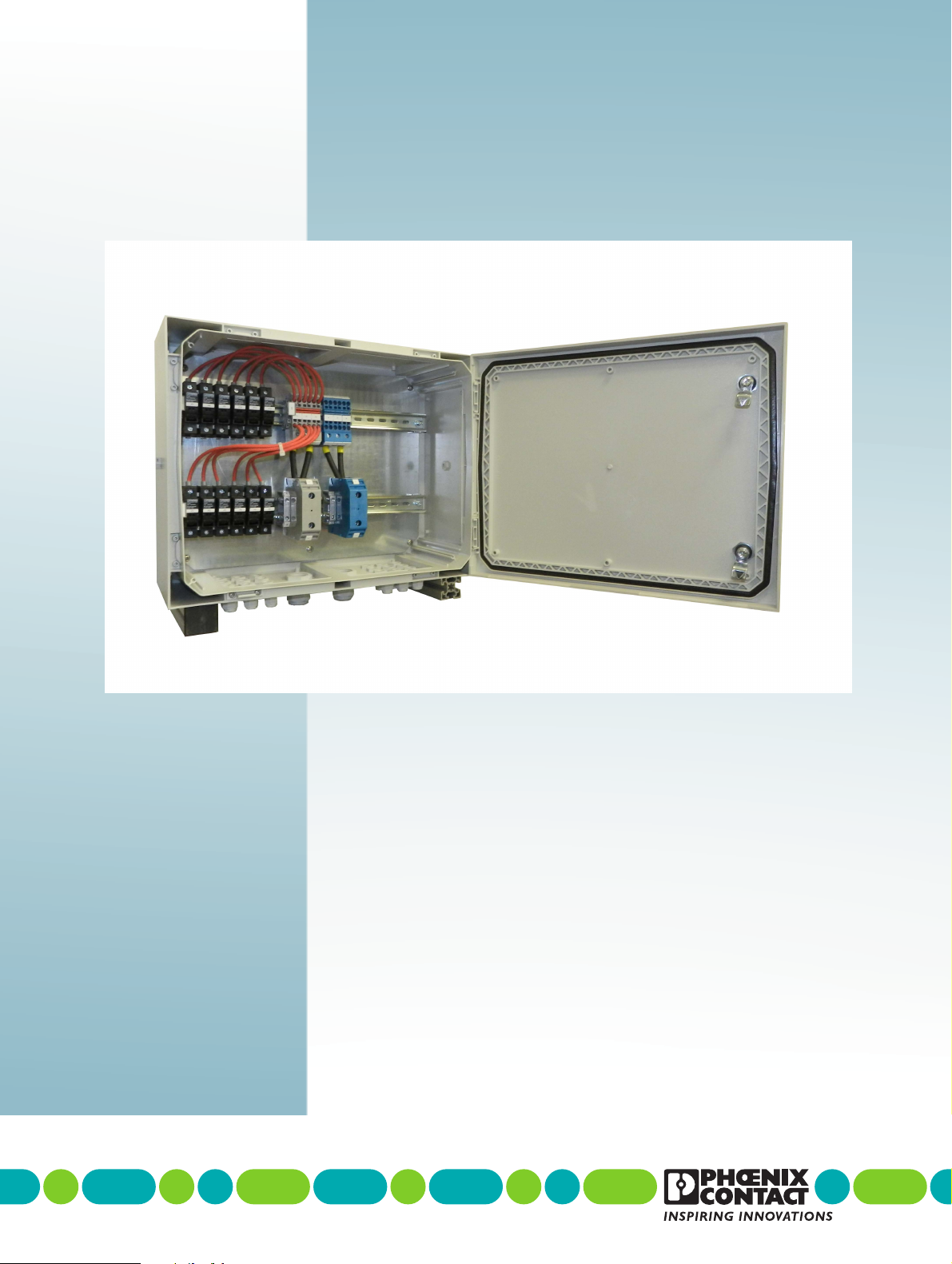
2Description
The CBL-DC-CMB1-10 switching device combination is a string combiner box for up to 12
or 14 photovoltaic strings. The solar string cables are guided through cable glands and into
the housing. The positive pole of the solar strings is connected to the UK 10,3-HESI 1000V
fuse modular terminal blocks and the negative pole of the solar strings is connected to the
STU 35/4x10 BU feed-through terminal blocks or as well to UK 10,3-HESI 1000V fuse modular terminal blocks. The output cables are connected to the UKH 150 and UKH 150 BU
high-current terminal blocks or to the load break switch.
Properties
– Degree of protection: IP65
– Housing: polycarbonate
– Connection of up to 12 or 14 solar strings
– UK 10.3 HESI 1000V fuse modular terminal blocks
3 Transport
The CBL-DC-CMB1-10 is delivered in cardboard packaging. Where necessary, the packaging features information on how to handle the packaged products as well as shock, tilt,
moisture, and temperature indicators. In order to avoid damage, this information must be
observed during both transport and storage.
The CBL-DC-CMB1-10 may only be transported to its destination in its original packaging.
Please observe the notes on the packaging. Secure the CBL-DC-CMB1-10 during transport, taking into account the center of gravity of the device. The same applies when relocating, moving or returning the equipment.
Internal transport is only permitted if the transport goods are adequately secured against
slipping and falling. Only use suitable floor conveyor vehicles.
Transport
3.1 Transportation method
The device must be kept horizontal during transport. The maximum permissible deviation
from the horizontal position is 15°. Only suitable and approved hoisting gear may be used
to unload and transport the equipment.
Do not climb onto the devices or packaging. However, if it should prove necessary, protect
the surfaces and frame to prevent damage. When transporting the equipment or storing it
temporarily, make sure that the surfaces are protected from the elements and any external
influences, and that they are kept dry and clean.
– Please observe the humidity specifications and the temperature range specified for
transport.
– Observe the warnings on the transport packaging.
– Observe the rupture load classes. This means that the least sensitive parts must be
placed at the bottom.
– Stretch and strap bulky goods.
106183_en_00 PHOENIX CONTACT 9
Page 10

CBL-DC-CMB1-10
4 Checking the delivery
4.1 Packaging
The contents of the packaging must be checked for completeness immediately upon delivery using the delivery note and/or parts list. The packaging of the CBL-DC-CMB1-10 must
not show any signs of external damage caused by transportation. Damaged packaging is
an indicator of potential damage to the CBL-DC-CMB1-10 that may have occurred during
transportation. This may cause the CBL-DC-CMB1-10 to malfunction.
Check the delivery for transport damage. Report any transport damage immediately.
– Keep the box and packaging material for checking purposes.
– Inform the manufacturer and/or your supplier immediately.
– Inform the transport company immediately.
4.2 Packaging when returning equipment
When returning the equipment, always use the original packaging. If the original packaging
is no longer available, it is essential to observe the following points. Most of the transport
damage that occurs during goods transportation is caused by incorrect handling of the
packaging.
– Please observe the humidity specifications and the temperature range specified for
storage/transport.
– If necessary, use dehumidifying agents.
– Protect electrostatically sensitive components and secure loose parts.
– Make sure that the packaging you select is large enough and sufficiently thick.
– Only use plastic bubble wrap sheets as wadding.
– Make sure that the goods cannot make contact with the outer walls of the cardboard
packaging.
– Attach warnings to the transport packaging so that they are clearly visible.
– Observe the rupture load classes. This means that the least sensitive parts must be
placed at the bottom.
– Please be aware that the delivery note is to be placed inside the package in the case of
packages that are to remain within the same country. However, if the package is being
sent abroad, the delivery note must be placed inside a delivery note pocket and at-
tached to the outside so that it is clearly visible.
– Stretch and strap bulky goods.
10
PHOENIX CONTACT 106183_en_00
Page 11

CBL-DC-CMB1-10
5 CBL-DC-CMB1-10
5.1 Ordering data
Products
Description Type Order No. Pcs. / Pkt.
String combiner box for up to 12 photovoltaic strings CBL-DC-CMB1-10 2400474 1
Accessories/replacement parts
Description Type Order No. Pcs. / Pkt.
Fuse, 10.3 mm x 38 mm, up to 1000 V DC, gPV characteristic FUSE 10,3X38 2A PV 3061295 10
Fuse, 10.3 mm x 38 mm, up to 1000 V DC, gPV characteristic FUSE 10,3X38 4A PV 3061305 10
Fuse, 10.3 mm x 38 mm, up to 1000 V DC, gPV characteristic FUSE 10,3X38 6A PV 3061318 10
Fuse, 10.3 mm x 38 mm, up to 1000 V DC, gPV characteristic FUSE 10,3X38 8A PV 3061321 10
Fuse, 10.3 mm x 38 mm, up to 1000 V DC, gPV characteristic FUSE 10,3X38 10A PV 3061334 10
Fuse, 10.3 mm x 38 mm, up to 1000 V DC, gPV characteristic FUSE 10,3X38 12A PV 3061347 10
Fuse, 10.3 mm x 38 mm, up to 1000 V DC, gPV characteristic FUSE 10,3X38 16A PV 3061350 10
Fuse, 10.3 mm x 38 mm, up to 1000 V DC, gPV characteristic FUSE 10,3X38 20A PV 3061363 10
Closing cap, for closing unused bore holes in multiple seals and cable glands,
diameter 8 mm.
SEALING PLUG 8X16 RD 1400257 10
Make sure you always use the latest documentation. It can be downloaded for the individual components at phoenixcontact.net/products.
5.2 Technical data
General data
Voltage (UN) DC 830 V
Max. continuous operating voltage (U
Rated insulation voltage (U
Max. short-circuit current (I
Max. combined short-circuit current (I
) DC 1000 V
I
SCSTC
Technical data
Housing Fibox Arca 405021, polycarbonate
Housing dimensions (W x H x D in mm) 500 x 400 x 210
Mounting plate MP 5040
Mounting plate dimensions (W x H in mm) 450 x 350
DIN rail NS 35/15 PERF, steel galvanized and thick layer passivated, perforated,
Weight 10 kg
Degree of protection IP65
Protection class (0, I, II, III) according to DIN EN 61140 II (without separate grounding device)
Color (RAL) RAL 7035
) DC 1000 V
CPV
) 16 A (per string)
) 192 A
SCSTC
height 15 mm, width 35 mm
106183_en_00 PHOENIX CONTACT 11
Page 12

CBL-DC-CMB1-10
Technical data
Type of cable entry Cable glands
Torques See “Torques for conductive connections” on page 16
Information on the installation location See installation site information in section
Ambient temperature (operation) -25°C … 60°C (derating above +45°C)
Ambient temperature (storage/transport) -40°C … 60°C
Humidity (operation/storage/transport) 5 ... 95 %, non-condensing
Altitude ≤ 2000 m (amsl (above mean sea level))
“General safety notes” on page 7
DC input
Number of strings 12
Fuse holder 12 x UK 10,3-HESI 1000 V
Fuse type 10.3 x 38 fuses for DC 1000 V
Fuse size 2 A … 20 A
Terminals for + side 3 x STU 35/ 4X10
Terminals for - side 3 x STU 35/ 4X10 BU
Cable glands 24 x M16
Clamping area 5 ... 10 mm
Conductor cross section 4 … 6 mm²
Terminal type for + side Screw connection with M5 screws
Terminal type for - side Spring connection
(see “Torques for conductive connections” on page 16)
DC output
Cable glands 2 x M32
Clamping area 18 ... 25 mm
Conductor cross section solid 35 … 95 mm²
Conductor cross section solid AWG 2 - 4/0
Conductor cross section stranded 50 … 95 mm²
Conductor cross section stranded AWG 1/0 - 4/0
Conductor material Copper or aluminum
When connecting aluminum conductors, please refer to the “Notes and product release list for connecting aluminum conductors” document. This can be
found at phoenixcontact.com in the download area for article 3010110.
Terminal type Screw connection with M10 screws
Terminal output for + side 1 x UKH 150
Terminal output for - side 1 x UKH 150 BU
(see “Torques for conductive connections” on page 16)
12
PHOENIX CONTACT 106183_en_00
Page 13

CBL-DC-CMB1-10
16,0
14,8
13,6
12,4
8,0
9,0
10,0
11,0
12,0
13,0
14,0
15,0
16,0
17,0
18,0
45 50 55 60
5.3 Derating diagram
The current per string must be decreased as shown in the derating diagram below, depending on ambient temperatures higher than +45°C. For each +1°C temperature increase, the
current per string must be decreased with 0,24A. The calculated derating is 1,5 % per +1°C,
in relation to the nominal current.
Current per string in A
Ambient temperature in °C
Figure 5-1 Current per string
Current per string
106183_en_00 PHOENIX CONTACT 13
Page 14

CBL-DC-CMB1-10
500,00
400,00
1
2
3
500,00
210,00
M32
M16M16
5.4 Housing dimensions
Figure 5-2 Housing dimensions/mounting plate layout - view from the front
Number BMK Component
1 F1 - F12 Fuse modular terminal block - UK 10,3-HESI 1000V
2 1+, 2+, 3+
4-, 5-, 6-
3 L+, L- High-current connector - UKH 150/UKH 150 BU
Feed-through terminal block - STU 35/ 4X10
Feed-through terminal block - STU 35/ 4X10 BU
Figure 5-3 Housing dimensions - view from below
14
PHOENIX CONTACT 106183_en_00
Page 15

CBL-DC-CMB1-10
5.5 Connection notes for mounting and installation
WARNING: Dangerous contact voltage
This work may only be carried out by qualified personnel who are familiar with the necessary safety precautions.
The electrical equipment for your system must be implemented in accordance with EN
60204 and the EMC Directive. Safety shoes must always be worn during mounting and removal. During mounting, the device must be held by a second person to prevent it from falling.
5.5.1 Space limits
When working on the CBL-DC-CMB1-10, make sure that there is sufficient room to move
and sufficient space available for the following activities:
– Mounting (W x H x D in mm): 1000 x 2000 x 1000
– Operation (W x H x D in mm): 1000 x 2000 x 1000
– Maintenance (W x H x D in mm): 1000 x 2000 x 1000
5.5.2 Mounting
WARNING: Risk of injury
– Mounting must always be carried out by two people.
– Observe the information on intended use in section “General safety notes” on page 7
of this quick start guide.
The switching device combination must not be installed on pulsating or vibrating machinery or equipment parts. Observe the maximum permissible attenuation according to the
transmission medium.
Protect bore holes and bare machining areas against corrosion.
Switching device combinations with a damaged housing must not be started up.
Mounting the switching device combination
Mount the switching device combination in the installation location using the four fixing clips
supplied as standard (Fibox MF CAB).
Check that the switching device combination is fixed securely.
106183_en_00 PHOENIX CONTACT 15
Page 16

CBL-DC-CMB1-10
5.5.3 Installation
DANGER: Return of the supply voltage
Make sure that switching on the input voltage cannot lead to hazardous situations.
DANGER: Please observe the following when wiring inside the switching device
combination
– Check the fuse protection inside the switching device combination.
– If accessing the wiring, check the marking of the individual wires and the equipment
identification in accordance with the circuit diagram and check the contact assignment in accordance with the switches and all other equipment.
Torques for conductive connections
Before establishing the supply voltage and starting up for the first time, check all conductive
connections in the CBL-DC-CMB1-10. If necessary, retighten these connections using a
torque screwdriver taking into account the torque values. When doing so, observe the information in the following table.
BMK Type Tightening torque
Min. Max.
-X1/2: -F1 ... -F12 UK 10,3-HESI 1000V 2 Nm 2.5 Nm
-X3: 1+ ... 3+
-X3: 4- ... 6-
-X4: L+; L- UKH 150/BU 25 Nm 25 Nm
STU 35/ 4X10
STU 35/ 4X10 BU
3.2 Nm 3.7 Nm
Connection
Installation must be performed by a skilled electrical engineer.
1. Open the switching device combination.
2. Release the cable entries.
3. Guide the cables into the cable entries.
4. Place filler plugs in unused cable entries.
5. Tighten the cable entries.
6. Strip the wires.
7. Connect the conductors. When doing so, refer to the circuit diagram and the informa-
tion under “Connections” on page 17.
8. Check and document the wiring.
9. Close the switching device combination.
16
PHOENIX CONTACT 106183_en_00
Page 17

CBL-DC-CMB1-10
M32
M16M16
1
4
2
3
5.5.4 Connections
WARNING: Dangerous contact voltage
Disconnect the power supply before starting work.
Cable feed-throughs
Figure 5-4 Cable feed-throughs on the underside of the housing (2 x M32, 24 x M16)
Table 5-1 Assignment of the cable feed-throughs
Number Connection/cable feed-through
1 Solar strings input (+)
2 DC 1000 V output (+)
3 DC 1000 V output (-)
4 Solar strings input (-)
Screw connection:
– For wiring use a screwdriver with the correct blade width.
– For a reliable and touch-proof connection, use a suitable cable cross section and insu-
late the cable ends according to the above-mentioned specifications.
Table 5-2 Connection terminal blocks
Terminal block Solid
conductor
[mm²]
Stranded
conductor
[mm²]
Stripping
length [mm]
Torque
[Nm]
UK 10,3-HESI 1000V 1.5 ... 25 0.75 ... 25 11 2 ... 2.5
UKH 150/BU 35 ... 150 50 ... 150 40 25 ... 30
Spring-cage connection:
Terminal block Solid
conductor
[mm²]
106183_en_00 PHOENIX CONTACT 17
STU 35/ 4X10 BU 0.2 ... 10 0.2 ... 6 12
Stranded
conductor
[mm²]
Stripping
length [mm]
Page 18

CBL-DC-CMB1-10
L+
L+
L-
-X4
-X4
L-
Connecting the output cables
Use copper or aluminum cables to connect the outlets.
Note the following when using aluminum conductors:
When connecting aluminum conductors, a non-conductive oxide film forms when the conductors are stripped. Aluminum conductors are only suitable for installation locations that
are free from humidity or aggressive atmospheres where possible.
– Separate the stripped end of the aluminum conductor from the oxide film using a
blade and immediately dip it in non-acid and non-alkali Vaseline.
– When connecting aluminum conductors, the screws must be tightened with the max-
imum permissible tightening torque (see table “Connection terminal blocks” on
page 17).
– Guide the cables through the cable entries and into the housing.
– Connect the conductors to terminals L+ and L-.
When doing so, refer to the figure and table below.
Figure 5-5 -X4: Terminals L+ and L- for output cables
Table 5-3 -X4: Terminals L+ and L-
BMK Description
-X4.L+ DC 1000 V (+)
-X4.L- DC 1000 V (-)
Connecting the PV strings
– Guide the cables through the cable entries and into the housing.
– Connect the conductors to the corresponding terminals.
When doing so, refer to the following figures and tables.
18
PHOENIX CONTACT 106183_en_00
Page 19

CBL-DC-CMB1-10
-F1 -F2 -F3 -F4 -F5 -F6
-X1
-F7 -F8 -F9 -F10 -F11 -F12
-X2
3+
3+
3+
6-
6-
6-
2+
2+
2+
5-
5-
5-
1+
1+
1+
4-
4-
4-
-X3
2
3
4
5
Connecting the positive solar strings
Figure 5-6 Fuse modular terminal blocks -F1 ... -F12
Table 5-4 Fuse modular terminal blocks -F1 ... -F12
BMK Description BMK Description
-F1 (+) cable string 1 -F7 (+) cable string 7
-F2 (+) cable string 2 -F8 (+) cable string 8
-F3 (+) cable string 3 -F9 (+) cable string 9
-F4 (+) cable string 4 -F10 (+) cable string 10
-F5 (+) cable string 5 -F11 (+) cable string 11
-F6 (+) cable string 6 -F12 (+) cable string 12
Connecting the negative solar strings
Figure 5-7 Terminal strip -X3 and circuit diagram STU 35/ 4X10 BU
Table 5-5 Terminal strip -X3
BMK Description BMK Description
4- (2) (-) cable string 1 5- (4) (-) cable string 9
4- (3) (-) cable string 2 5- (5) (-) cable string 10
4- (4) (-) cable string 7 6- (2) (-) cable string 5
4- (5) (-) cable string 8 6- (3) (-) cable string 6
5- (2) (-) cable string 3 6- (4) (-) cable string 11
5- (3) (-) cable string 4 6- (5) (-) cable string 12
106183_en_00 PHOENIX CONTACT 19
Page 20

CBL-DC-CMB1-10
20
PHOENIX CONTACT 106183_en_00
Page 21

6Startup
DANGER: Return of the supply voltage
Make sure that switching on the input voltage cannot lead to unexpected hazardous situations.
All work on the CBL-DC-CMB1-10 must only be carried out by qualified personnel who
are familiar with the necessary safety precautions.
Do not start up the CBL-DC-CMB1-10 until it has been properly mounted and installed.
Make sure that all of the necessary steps described in section „Connection notes for mounting and installation“ have been performed.
7Servicing/cleaning
WARNING: Dangerous contact voltage
All servicing work must only be carried out by qualified personnel who are familiar with the
necessary safety precautions.
Startup
All electrical equipment must be kept in good condition as stipulated by the relevant standards and regulations, e.g., DIN VDE 0105-100 and accident prevention regulation BGV A3
(electrical systems and equipment).
Check the CBL-DC-CMB1-10 at regular intervals, at least once a year. The servicing interval also depends on the usage and ambient conditions. Parts and components that are subject to frequent use/loads must be checked at shorter intervals. Any defects to the CBL-DCCMB1-10 must be eliminated as soon as they are identified. If a defective electrical system
poses an immediate danger, it must not continue to be operated.
If there is any risk of material damage or personal injury, the CBL-DC-CMB1-10 must be
stopped immediately. Before it can be started up again, the CBL-DC-CMB1-10 must be returned to a safe condition. Before carrying out any servicing work with the power supply disconnected, observe the five basic safety rules, provided these apply to your application:
– Disconnect safely
– Ensure power cannot be switched on again
– Verify safe isolation from the supply
– Ground and short circuit
– Cover or safeguard adjacent live parts
Document all servicing steps performed. Example information:
– Date/serial or device number/equipment identification
– State of the object undergoing the check
– Activity carried out
– Repairs/adjustments/replacement/settings, etc.
– Skilled electrical engineer carrying out the work
When carrying out regular checks and servicing work on the CBL-DC-CMB1-10, observe
the points described in the following sections in particular and also the specifications from
the corresponding standards and guidelines.
106183_en_00 PHOENIX CONTACT 21
Page 22

CBL-DC-CMB1-10
7.1 Servicing with the power supply disconnected
WARNING: Dangerous contact voltage
– Before carrying out any servicing work on the device, disconnect the power.
– With load break switch:
Turn the load break switch to position „0 OFF“. This interrupts the DC current of
the CBL-DC-CMB1-10.
– Without load break switch:
Disconnect the DC circuit at the inverter. This interrupts the DC current of the
CBL-DC-CMB1-10. Please note the instructions in the manual of the manufacturer.
– Open the fuse holder of the fuse modular terminal blocks in the CBL-DC-CMB1-
10 to disconnect the corresponding string current.
Warning: Never open the fuse terminal blocks under load.
– Check the fuses and replace them when necessary.
– All servicing work must only be carried out by qualified personnel who are familiar
with the necessary safety precautions.
Visual inspection of cabling and components
– Check the CBL-DC-CMB1-10 for visible damage. Only operate the device in a fault-free
state that ensures operational reliability.
– Check all components, cables, terminal points, conductor connections, and markings
regularly and compare these to the circuit diagram and associated documentation.
– Check the strain relief of the cables.
– Check that all cable glands are fixed securely and sealed.
– Check the cable routing and bending radii.
– Check the cables, cable connections, and components for signs of overheating, e.g.,
discoloration or deformation. Replace any affected components and cables where nec-
essary. The source/trigger of overheating must be identified before the device can be
started up again and returned to a safe condition.
– Check the tightening torques of all connections.
Tighten any loose connections taking into account the maximum torque (see „Torques
for conductive connections“).
– Check all connections for a secure fit and correct functioning.
– Perform this check at least once a year.
– Parts and components that are subject to frequent use/loads must be checked at short-
er intervals.
Housings and seals
– Check the housing for visible damage and corrosion.
– Remove any soiling. Refer to the information in the Cleaning section.
– Check that the housing doors lock correctly and also check the function of the lock.
– Check that the doors open and close correctly. If necessary, lubricate the hinges.
– Check that the housing is sealed and ensure that there is no condensation in the interi-
or.
– All seals must be maintained at regular intervals to ensure that the housing offers the
appropriate degree of protection.
– Check the seals for deformation, cracks, and soiling.
22
PHOENIX CONTACT 106183_en_00
Page 23

Servicing/cleaning
– Use warm soapy water and a soft brush to clean the seals.
– Do not use any aggressive cleaning agents.
– Condition the seals with suitable care products.
– Observe the servicing schedule in the manufacturer's mounting and instruction manual.
Space limits/safe mounting/installation site
– Check the space limits at the installation location. The prescribed space limits for oper-
ation and servicing must be observed to ensure safety and must be restored if neces-
sary.
– Check that the CBL-DC-CMB1-10 is securely fixed in the installation location (e.g.,
screw connection in the case of wall fastening).
– Ensure that the CBL-DC-CMB1-10 is suitable for the conditions at the installation site.
7.2 Maintenance
WARNING: Dangerous contact voltage
– Before carrying out maintenance work on the device, disconnect the power.
– All maintenance work must only be carried out by qualified personnel who are familiar
with the necessary safety precautions.
7.2.1 Corrective maintenance
For corrective maintenance, proceed as follows:
1. The voltage must be disconnected by the user/a skilled electrical engineer.
2. Open the switching device combination.
3. Replace the faulty equipment.
4. The voltage must be switched on by the user/a skilled electrical engineer.
5. Close the switching device combination.
7.2.2 Troubleshooting/error removal
For troubleshooting/error removal, proceed as follows:
1. Open the switching device combination.
2. Troubleshooting inside the switching device combination.
3. Perform a visual inspection.
4. If necessary, perform voltage measurements.
5. Once all errors have been detected, proceed as described in Section 7.2.1, “Corrective
maintenance”.
6. Close the switching device combination.
106183_en_00 PHOENIX CONTACT 23
Page 24

CBL-DC-CMB1-10
7.3 Cleaning
Cleaning the housing
Clean the outside surfaces of the housing with a damp cloth. Do not use any corrosive
cleaning agents, thinners, abrasive cleaners or hard objects that could damage the surface.
8Removal/disposal
To decommission a system, proceed according to the procedures specified by the machine
or system manufacturer. When decommissioning the switching device combination or parts
thereof, ensure that the components used:
– Are correctly reused in another system.
Or
– Are disposed of according to the applicable environmental regulations, and in this case
can never be reused.
Safety shoes must always be worn during mounting and removal. During removal, the
switching device combination must be held by a second person to prevent it from falling.
During decommissioning/removal, make sure that there is sufficient space available.
Removal procedure:
– The voltage must be disconnected by the user/a skilled electrical engineer.
– Open the CBL-DC-CMB1-10.
– Loosen the wires.
– Release the cable entries and pull out the cables.
– Close the CBL-DC-CMB1-10.
– Secure the CBL-DC-CMB1-10 to prevent it from falling.
– Release the mounting screws on the CBL-DC-CMB1-10.
– Remove the CBL-DC-CMB1-10.
9 Storage and storage conditions
The storage location should be dry and protected against harmful environmental influences
such as UV light.
– Temperature range: -40°C ... 60°C
– Air pressure: 2000 m above sea level, maximum
– Permissible humidity (storage/transport): 5% ... 95%
24
PHOENIX CONTACT 106183_en_00
 Loading...