

Page 1
EN
Changeover facility for Sunny Backup systems
AUTOMATIC SWITCH BOX XL
Installation Guide
AS-BOX-XL-IEN094410 | 98-2012910 | Version 1.0
Page 2

Page 3

SMA Solar Technology AG Table of Contents
Table of Contents
1 Notes on this Guide . . . . . . . . . . . . . . . . . . . . . . . . . . . . . . . 7
1.1 Area of Validity. . . . . . . . . . . . . . . . . . . . . . . . . . . . . . . . . . . . . . 7
1.2 Additional Information . . . . . . . . . . . . . . . . . . . . . . . . . . . . . . . . 7
1.3 Symbols Used . . . . . . . . . . . . . . . . . . . . . . . . . . . . . . . . . . . . . . . 8
2 Safety . . . . . . . . . . . . . . . . . . . . . . . . . . . . . . . . . . . . . . . . . . 9
2.1 Appropriate Usage. . . . . . . . . . . . . . . . . . . . . . . . . . . . . . . . . . . 9
2.2 Safety precautions . . . . . . . . . . . . . . . . . . . . . . . . . . . . . . . . . . 11
3 Unpacking. . . . . . . . . . . . . . . . . . . . . . . . . . . . . . . . . . . . . . 12
3.1 Packing List . . . . . . . . . . . . . . . . . . . . . . . . . . . . . . . . . . . . . . . . 12
3.1.1 Automatic Switch Box . . . . . . . . . . . . . . . . . . . . . . . . . . . . . . . . . . . . . . . . . . 12
3.1.2 Multicluster Piggy-Back (optional). . . . . . . . . . . . . . . . . . . . . . . . . . . . . . . . . 13
3.2 Identifying the Automatic Switch Box . . . . . . . . . . . . . . . . . . . . 13
4 Installation . . . . . . . . . . . . . . . . . . . . . . . . . . . . . . . . . . . . . 14
4.1 Selecting the installation location . . . . . . . . . . . . . . . . . . . . . . . 14
4.2 Transport. . . . . . . . . . . . . . . . . . . . . . . . . . . . . . . . . . . . . . . . . . 15
4.2.1 Transport Options . . . . . . . . . . . . . . . . . . . . . . . . . . . . . . . . . . . . . . . . . . . . . 15
4.2.2 Transporting the Automatic Switch Box. . . . . . . . . . . . . . . . . . . . . . . . . . . . . 16
4.3 Installing the Automatic Switch Box . . . . . . . . . . . . . . . . . . . . . 17
4.3.1 Free-standing Installation. . . . . . . . . . . . . . . . . . . . . . . . . . . . . . . . . . . . . . . . 17
4.3.2 Wall Mounting . . . . . . . . . . . . . . . . . . . . . . . . . . . . . . . . . . . . . . . . . . . . . . . 18
5 Electrical Connection . . . . . . . . . . . . . . . . . . . . . . . . . . . . . 20
5.1 System Overview (Sunny Backup XL-System with 2 clusters) . . 20
5.2 Overview of the Connection Area . . . . . . . . . . . . . . . . . . . . . . 21
5.2.1 Underside view (without base) . . . . . . . . . . . . . . . . . . . . . . . . . . . . . . . . . . . 21
5.2.2 Interior View . . . . . . . . . . . . . . . . . . . . . . . . . . . . . . . . . . . . . . . . . . . . . . . . . 22
5.3 Preparing the cables . . . . . . . . . . . . . . . . . . . . . . . . . . . . . . . . . 24
Installation Guide AS-BOX-XL-IEN094410 3
Page 4

Table of Contents SMA Solar Technology AG
5.4 Connecting the cables . . . . . . . . . . . . . . . . . . . . . . . . . . . . . . . 25
5.4.1 Connecting Consumer Loads . . . . . . . . . . . . . . . . . . . . . . . . . . . . . . . . . . . . 25
5.4.2 Connecting the PV System. . . . . . . . . . . . . . . . . . . . . . . . . . . . . . . . . . . . . . . 27
5.4.3 Connecting the Feed-in Meter. . . . . . . . . . . . . . . . . . . . . . . . . . . . . . . . . . . . 29
5.4.4 Connecting the Consumption Meter . . . . . . . . . . . . . . . . . . . . . . . . . . . . . . . 32
5.4.5 Connecting the Battery . . . . . . . . . . . . . . . . . . . . . . . . . . . . . . . . . . . . . . . . . 34
5.4.6 Connecting the Sunny Backup . . . . . . . . . . . . . . . . . . . . . . . . . . . . . . . . . . . 35
5.4.7 Connecting a Generator (Optional) . . . . . . . . . . . . . . . . . . . . . . . . . . . . . . . 37
5.5 Communication. . . . . . . . . . . . . . . . . . . . . . . . . . . . . . . . . . . . . 39
5.5.1 Routing cables into the Automatic Switch Box . . . . . . . . . . . . . . . . . . . . . . . 39
5.5.2 Connecting the control and sensor cables . . . . . . . . . . . . . . . . . . . . . . . . . . 42
5.5.3 Connecting the communication cable . . . . . . . . . . . . . . . . . . . . . . . . . . . . . . 42
6 Commissioning the Automatic Switch Box. . . . . . . . . . . . 43
7 Opening and Closing. . . . . . . . . . . . . . . . . . . . . . . . . . . . . 44
7.1 Opening the Automatic Switch Box . . . . . . . . . . . . . . . . . . . . . 44
7.2 Closing the Automatic Switch Box . . . . . . . . . . . . . . . . . . . . . . 44
8 Decommissioning . . . . . . . . . . . . . . . . . . . . . . . . . . . . . . . . 45
8.1 Disassembling the Automatic Switch Box . . . . . . . . . . . . . . . . . 45
8.2 Storing the Automatic Switch Box. . . . . . . . . . . . . . . . . . . . . . . 45
8.3 Disposing of the Automatic Switch Box . . . . . . . . . . . . . . . . . . 45
9 Technical Data . . . . . . . . . . . . . . . . . . . . . . . . . . . . . . . . . . 46
10 Contact . . . . . . . . . . . . . . . . . . . . . . . . . . . . . . . . . . . . . . . . 49
4 AS-BOX-XL-IEN094410 Installation Guide
Page 5

SMA Solar Technology AG Table of Contents
Installation Guide AS-BOX-XL-IEN094410 5
Page 6

Table of Contents SMA Solar Technology AG
6 AS-BOX-XL-IEN094410 Installation Guide
Page 7

SMA Solar Technology AG Notes on this Guide
1 Notes on this Guide
This manual describes the assembly and installation of the Automatic Switch Box XL. This manual
replaces the assembly and installation instructions in the technical description of the Sunny Backup
5000, version 2.0.
Store this manual where it can be accessed at all times.
1.1 Area of Validity
This manual is valid for the type AS-BOX-XL.
1.2 Additional Information
Additional information regarding the Sunny Backup-System and the Automatic Switch Box can be
found in the FAQ section at www.SMA.de/en.
Additional Sunny Backup-System certificates can be found on the Internet at www.SMA.de/en.
Installation Guide AS-BOX-XL-IEN094410 7
Page 8
Notes on this Guide SMA Solar Technology AG
1.3 Symbols Used
The following types of safety precautions and general information are used in this manual:
DANGER!
DANGER indicates a hazardous situation which, if not avoided, will result in death or
serious injury.
WARNING!
WARNING indicates a hazardous situation which, if not avoided, could result in death or
serious injury.
CAUTION!
CAUTION indicates a hazardous situation which, if not avoided, could result in minor or
moderate injury.
ATTENTION!
NOTICE indicates a situation that can result in property damage, if not avoided.
Information
Information provides tips that are valuable for the optimal operation of your product.
8 AS-BOX-XL-IEN094410 Installation Guide
Page 9

SMA Solar Technology AG Safety
2 Safety
2.1 Appropriate Usage
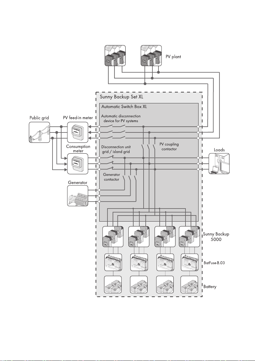
The Automatic Switch Box is a changeover facility for Sunny Backup-Systems. Sunny Backup regulates
and controls the Automatic Switch Box and acts as an island grid in case of a power outage. During
a power outage, the Automatic Switch Box safely disconnects the connected PV system and the
connected consumer loads from the public grid and connects them to the island grid.
You have the option of integrating a generator into the Sunny Backup-System providing you selected
the "Generator connection" feature when ordering the Automatic Switch Box. The generator
connection can be ordered as an option but cannot be retrofitted.
If a generator is integrated into the Sunny Backup-System, the Automatic Switch Box switches it to the
island grid if necessary.
Connection requirements
The Sunny Backup-System is only certified for TN grids and may not be installed in TT grids.
The Automatic Switch Box may only be operated in conjunction with 6, 9 or 12 Sunny Backup
(in2to4 clusters).
The Sunny Backup-Master of the Main Cluster evaluates the data recorded in the Automatic Switch
Box, coordinates all switching operations and controls all components of the Sunny Backup-System.
The maximum connection power of the individual outgoing lines in the Automatic Switch Box may not
be exceeded.
Do not use the Automatic Switch Box for purposes other than those described here. Alternative uses,
modifications, and the installation of components void the warranty claims and operation permit.
Installation Guide AS-BOX-XL-IEN094410 9
Page 10
Safety SMA Solar Technology AG
Principle of the Automatic Switch Box in a Sunny Backup-System
10 AS-BOX-XL-IEN094410 Installation Guide
Page 11

SMA Solar Technology AG Safety
2.2 Safety precautions
DANGER!
Danger to life due to high voltages in the Automatic Switch Box.
• All work on the Automatic Switch Box must be performed by qualified personnel.
Problems while performing the described activities
If you have problems while performing any of the activities described in this manual,
contact SMA Solar Technology AG (see Section 10”Contact” (page49)).
Installation Guide AS-BOX-XL-IEN094410 11
Page 12
Unpacking SMA Solar Technology AG
3 Unpacking
3.1 Packing List
Check that the delivery is complete. Check the packaging and the Automatic Switch Box for any
visible external damage. Contact your supplier in case of damage to the packaging. Contact your
dealer if you find any damage to the Automatic Switch Box or if there are parts missing.
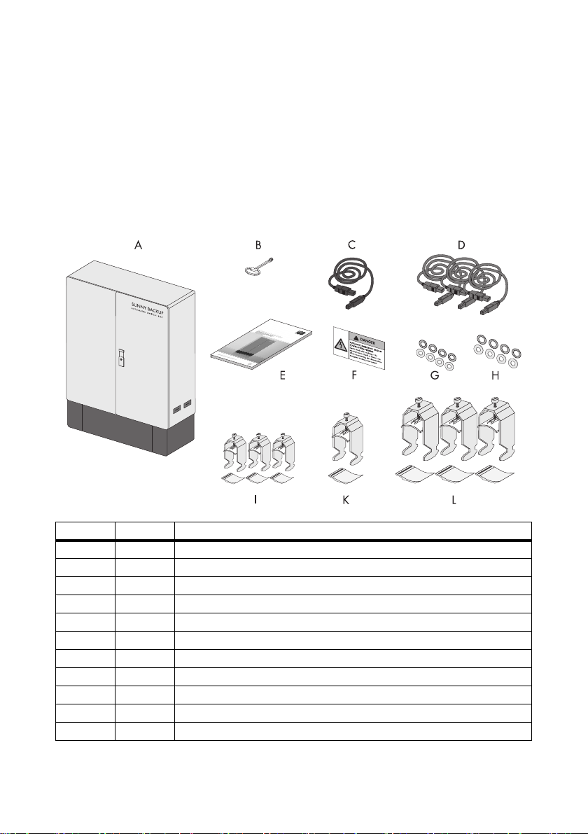
3.1.1 Automatic Switch Box
Object Number Description
A1Automatic Switch Box
B 1 Switch cabinet key
C 1 Communication cable (black)
D 3 Control and sensor cable (red)
E 1 Installation Guide
F 8 Sticker (hazard warning for consumer load system)
G 8 4 sealing washers and 4 washers (diameter: 6 mm)
H 8 4 sealing washers and 4 washers (diameter: 8 mm)
I 3 cable clip and counter well (22 mm .... 28 mm)
K 1 cable clip and counter well (52 mm .... 58 mm)
L 3 cable clip and counter well (58 mm .... 64 mm)
12 AS-BOX-XL-IEN094410 Installation Guide
Page 13
SMA Solar Technology AG Unpacking
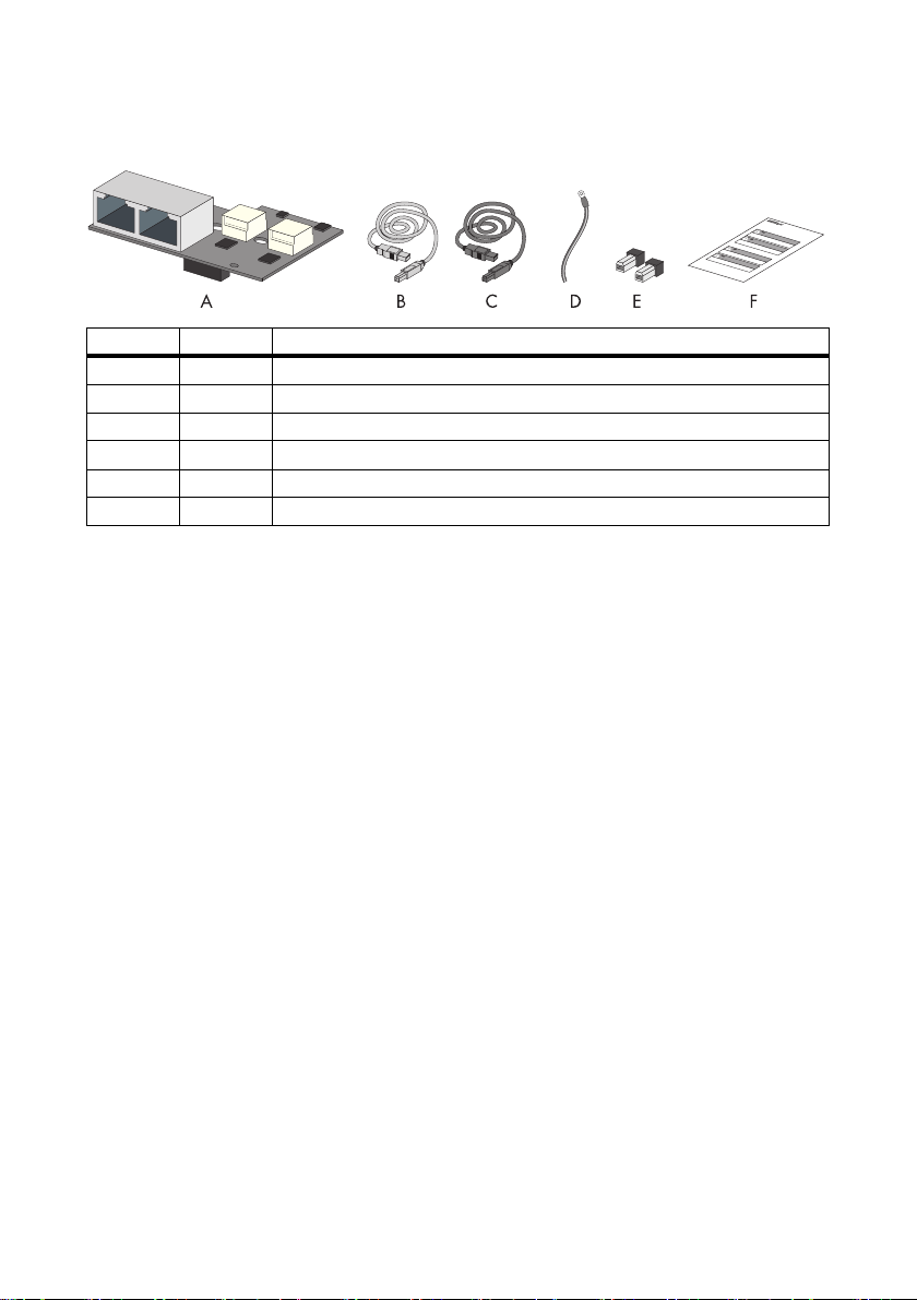
3.1.2 Multicluster Piggy-Back (optional)
Object Number Description
A 2 - 4 Multicluster Piggy-Back
B 2 - 4 RJ45 cable (5 m, yellow)
C 2 - 4 RJ45 cable (5 m, gray)
D 2 - 4 Grounding cable
E 4 - 8 Termination resistor
F 1 Technical Description
3.2 Identifying the Automatic Switch Box
Identify the Automatic Switch Box by the serial number (Serial No.) and the device type (Type /
Model) on the type label. The type label is on the right side of the enclosure.
Installation Guide AS-BOX-XL-IEN094410 13
Page 14
Installation SMA Solar Technology AG
4 Installation
4.1 Selecting the installation location
DANGER!
Danger to life due to fire or explosion.
Despite careful construction, electrical devices can cause fires.
• Do not mount the Automatic Switch Box on flammable construction materials.
• Do not mount the Automatic Switch Box near highly inflammable materials.
• Do not mount the Automatic Switch Box in potentially explosive areas.
Comply with the following conditions when selecting the mounting location:
• Install the product on a solid surface, e.g. a concrete base.
• The installation location must be accessible at all times.
• Comply with the appropriate minimum passage widths and escape routes
• Installation is vertical.
Properties of the foundation
The foundation must provide a solid and secure base for the Automatic Switch Box. When selecting
the foundation, remember that the Automatic Switch Box weighs 180 kg. Do not install the Automatic
Switch Box on an incline. Level out any existing unevenness or subsidence.
14 AS-BOX-XL-IEN094410 Installation Guide
Page 15
SMA Solar Technology AG Installation
4.2 Transport
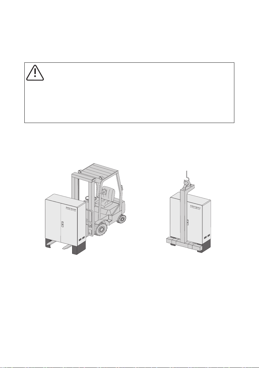
4.2.1 Transport Options
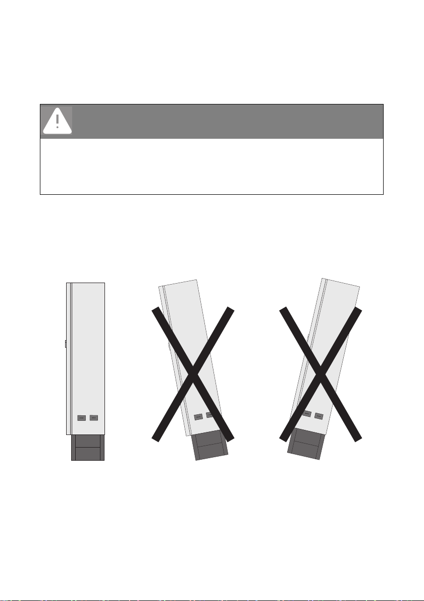
CAUTION!
Risk of injury due to the heavy weight of the Automatic Switch Box.
• T he m ean s of tra nsp ort ati on m ust be a deq uat e fo r th e we igh t of the Aut oma tic Swi tch
Box.
• Only transport the Automatic Switch Box upright.
• Take the center of gravity of the Automatic Switch Box into account. It is located in
the upper third of the device.
The Automatic Switch Box is delivered on a pallet. To lift the Automatic Switch Box from the pallet,
you can use the following transport vehicles:
• Forklift or pallet truck
• Crane with appropriate fork
Installation Guide AS-BOX-XL-IEN094410 15
Page 16
Installation SMA Solar Technology AG
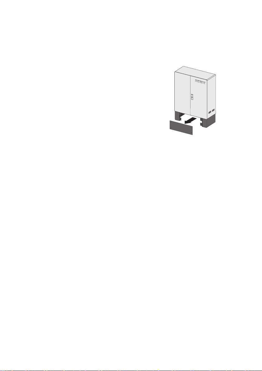
4.2.2 Transporting the Automatic Switch Box
1. Remove all fastening screws from the base panel front and back.
2. Put the screws aside. The screws will be needed later to reattach the base panels.
3. Remove the base panels and set them aside.
4. Bring the fork of the lift truck, pallet truck, or crane into place under the Automatic Switch Box
and move the Automatic Switch Box to the installation location.
☑ The Automatic Switch Box is now located at the place of installation.
16 AS-BOX-XL-IEN094410 Installation Guide
Page 17
SMA Solar Technology AG Installation
4.3 Installing the Automatic Switch Box
The Automatic Switch Box is fixed onto the foundation by its base. If the Automatic Switch Box is to
be installed not in a free-standing position, but next to a wall, you can also fix the rear panel to the
wall.
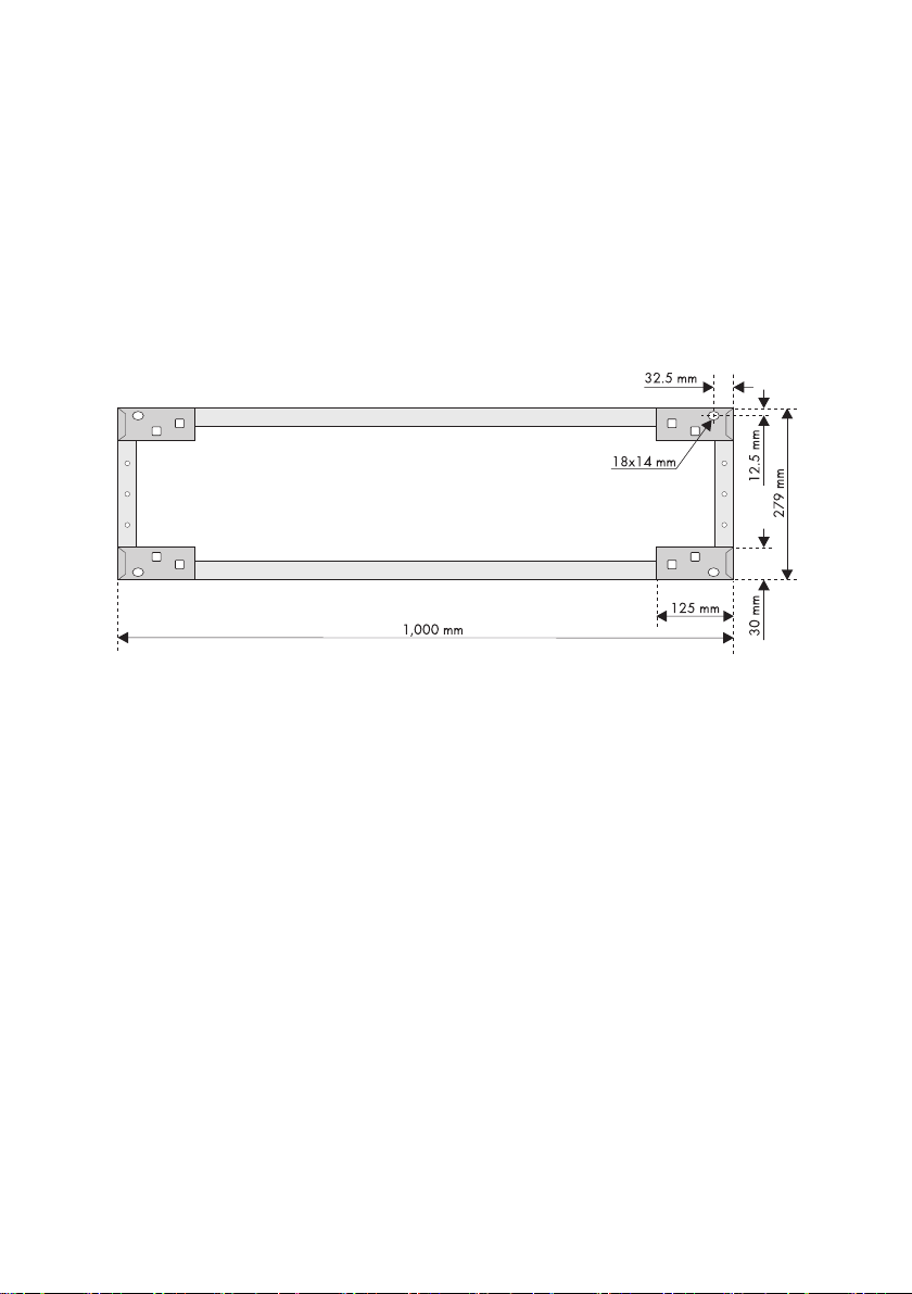
4.3.1 Free-standing Installation
If the Automatic Switch Box is to be mounted in a free-standing position, proceed as follows:
1. Mark the position of the drill holes for fastening the base.
2. Drill the holes in the marked positions
3. Insert appropriate fastening material.
4. Place the Automatic Switch Box on the foundation. Please refer to Section 4.2”Transport”
(page15).
5. Fasten the Automatic Switch Box to the foundation.
☑ The Automatic Switch Box is now mounted.
Installation Guide AS-BOX-XL-IEN094410 17
Page 18

Installation SMA Solar Technology AG
4.3.2 Wall Mounting
If the Automatic Switch Box is to be mounted and fixed to a wall, proceed as follows:
1. Mark the position of the drill holes for fastening the base.
18 AS-BOX-XL-IEN094410 Installation Guide
Page 19

SMA Solar Technology AG Installation
2. Mark the position of the drill holes for fastening the rear panel.
3. Drill holes at the marked positions.
4. Insert appropriate fastening material.
5. Place the Automatic Switch Box on the foundation and against the wall. Please refer to Section
4.2”Transport” (page15).
6. Attach the Automatic Switch Box to the wall using 2 suitable screws and the supplied seals and
washers.
7. Attach the Automatic Switch Box to the foundation using 2 suitable bolts.
☑ The Automatic Switch Box is now mounted and attached to the wall.
Installation Guide AS-BOX-XL-IEN094410 19
Page 20

Electrical Connection SMA Solar Technology AG
5 Electrical Connection
5.1 System Overview (Sunny Backup XL-System with 2 clusters)
20 AS-BOX-XL-IEN094410 Installation Guide
Page 21

SMA Solar Technology AG Electrical Connection
5.2 Overview of the Connection Area
5.2.1 Underside view (without base)
Object Description
A Flange plate with membranes for feed-through of connection cables
Installation Guide AS-BOX-XL-IEN094410 21
Page 22

Electrical Connection SMA Solar Technology AG
5.2.2 Interior View
22 AS-BOX-XL-IEN094410 Installation Guide
Page 23

SMA Solar Technology AG Electrical Connection
Object Description
A RJ45 sockets for connecting the control and sensor cables
B RJ45 sockets for connecting the communication cable
C Connection terminals "=AS-X2 All Cluster" to connect the Sunny Backup
(N, PE)
D Optional connection area (terminals "=1_1-X6 Generator" and fuse element
"=1_1-F6 Generator") for connection of the generator
E Connection terminal "=AS-X1/Load Meter" for connecting the consumption meter
F Connection terminal "=AS-X5 PV Meter" for connecting the feed-in meter
G Connection terminals "=AS-X4 PV system" for connecting the PV system
H Connection terminals "=AS-X3 Backup Loads" and fuse element
"=AS‑F3BackupLoads" for connecting consumer loads
I Connection terminals "=AS-X10 Auxiliary Voltage (48 V)" for connecting the
battery
J Line circuit breaker for connecting the Sunny Backup (L)
Installation Guide AS-BOX-XL-IEN094410 23
Page 24

Electrical Connection SMA Solar Technology AG
5.3 Preparing the cables
ATTENTION!
Penetration of moisture and dust can damage the Automatic Switch Box.
If the rubber membranes on the underside of the Automatic Switch Box are overstretched,
moisture and dust can penetrate into the Automatic Switch Box.
• When inserting the cables, observe the minimum and maximum diameters of the
rubber membranes. See Section 5.3”Preparing the cables” (page24).
1. Select a suitable membrane for the insertion of the relevant cable.
2. Pierce the selected membrane with a pointed object. The opening must not be too large.
3. Lead the cable throught the membrane into the interior of the Automatic Switch Box. After
insertion, the cable must be tightly enclosed by the membrane.
4. Strip the insulation off the cable and mount a corresponding cable lug.
Only strip the Sunny Backup and battery cables, but do not attach any cab le l ugs. These cables
will be connected to spring-type terminals.
5. Attach cord-end sleeves to the Sunny Backup and battery cables.
☑ The cables are now ready.
6. Connect the cables as described in the following sections.
ATTENTION!
Loose cables can damage the Automatic Switch Box.
If there is excessive mechanical strain on the cables, they may come loose from the
terminals.
• Trap cables in the Automatic Switch Box on the cable support rail provided for that
purpose. Use the supplied cable clips and counter wells.
24 AS-BOX-XL-IEN094410 Installation Guide
Page 25

SMA Solar Technology AG Electrical Connection
5.4 Connecting the cables
CAUTION!
Risk of burns when opening and closing the fuse load disconnector (NH load
disconnector) under load.
Opening or closing the fuse load disconnector (NH load disconnector) under load causes
sparking.
• Wear personal protective equipment.
Connection terminal torques
When connecting the cables, be sure to observe the torques of the individual connection
terminals given in Section 9”Technical Data” (page46).
5.4.1 Connecting Consumer Loads
The phases L1, L2, and L3 are led through fuse elements in the Automatic Switch Box. The fuses are
necessary in order to protect the output cable from overload in island grid operation. Beware that the
currents from the Sunny Backup, the PV system, and possibly the generator, may be summated.
Determine the required fuse size according to type of cable routing and installation conditions, and
insert the appropriate fuse plugs. The maximum usable fuse plugs are factory-installed in the
respective fuse element.
Sizing the thermal fuse
Use the table to select the condition that applies to you and observe the corresponding SMA Solar
Technology AG recommendation.
Condition Recommendation
The rating of the back-up fuse in the
distribution is equal to the nominal
current of the Automatic Switch Box
during grid operation (160 A).
The rating of the back-up fuse in the
distribution is lower than the nominal
current of the Automatic Switch Box
during grid operation (160 A).
The rating of the back-up fuse in the
distribution is higher than the nominal
current of the Automatic Switch Box
(160 A).
Installation Guide AS-BOX-XL-IEN094410 25
• Insert a fuse with a nominal current of 160 A into the
"=AS-F3 Backup Loads" fuse element.
• Insert a fuse with the same nominal current as in the
distribution into the "=AS-F3 Backup Loads" fuse
element.
• Use Sunny Backup parameter
"232.02 GdCurNom" to set the maximum grid
current to the value of the back-up fuse.
• Insert a fuse with max. 160 A into the
"=AS‑F3Backup Loads" fuse element in accordance
with the installation.
Page 26

Electrical Connection SMA Solar Technology AG
Connection Procedure
1. Prepare the cables as described in Section 5.3”Preparing the cables” (page24).
2. Connect PE and N to the "=AS-X3 Backup Loads" connection terminal according to the labels.
The second connection terminal "N" is not assigned.
3. Connect L1, L2, and L3 to the fuse element "=AS-F3 Backup Loads" according to the labels.
☑ The consumer loads are now connected.
26 AS-BOX-XL-IEN094410 Installation Guide
Page 27

SMA Solar Technology AG Electrical Connection
5.4.2 Connecting the PV System
Cable protection
The Automatic Switch Box does not replace the distributor box or fuse box of the PV system
(PV main distributor).
Install a load disconnection unit and a corresponding fuse element between the Automatic
Switch Box and the PV system. Be sure to observe all standards and guidelines applicable
to the installation site.
Connecting other energy sources
Instead of a PV system, you can connect other energy sources (e.g. small wind turbine
systems) to the Automatic Switch Box. In any case, make sure that a counter with the
corresponding tariff is connected to the Automatic Switch Box.
Mixing energy sources (e.g., connection of a PV system and a small wind turbine system)
is not permitted by the utility operator, as the feed-in tariff for each energy source is
different.
Cable Sizing
The cable type and routing method must be suitable for the application and the deployment location.
Select the cable according to the upstream fuse on the grid side.
For a Sunny Backup-System with a generator, also pay attention to the fuse protection rating of the
generator feed-in. If the generator feed-in at the "1_1-F6 Generator" connection terminal has a higher
fuse rating than the supply cable from the feed-in meter (upstream of "AS-X5 PV Meter"), you need to
dimension the output cable from the PV system (AS-X4 PV System) according to this higher fuse value.
Installation Guide AS-BOX-XL-IEN094410 27
Page 28

Electrical Connection SMA Solar Technology AG
Connection Procedure
1. Prepare the cables as described in Section 5.3”Preparing the cables” (page24).
2. Connect PE and N to the "=AS-X4 PV System" terminal according to the labels.
3. Connect L1, L2, and L3 to the "=AS-X4/PV System" terminal according to the labels.
☑ The PV system is now connected to the Automatic Switch Box.
28 AS-BOX-XL-IEN094410 Installation Guide
Page 29

SMA Solar Technology AG Electrical Connection
5.4.3 Connecting the Feed-in Meter
Cable protection
For purposes of fuse protection and isolation, install a line circuit breaker between the
Automatic Switch Box and the feed-in meter. Be sure to observe all standards and
guidelines applicable to the installation site.
Connection requirements
The Sunny Backup-System is only certified for TN grids and may not be installed in TT grids.
Comply with all connection regulations of the utility operator.
PV systems without a feed-in meter
The Sunny Backup-System can also be used in PV systems without a feed-in meter. If you
do not connect a feed-in meter to the Automatic Switch Box, you must bridge the feed-in
meter (=AS-X5 PV Meter) and the consumption meter (=AS-X1 Load Meter) outside the
Automatic Switch Box.
Installation Guide AS-BOX-XL-IEN094410 29
Page 30

Electrical Connection SMA Solar Technology AG
Principle of an Automatic Switch Box in a Sunny Backup-System with an external
bridge between the feed-in meter and the consumption meter
30 AS-BOX-XL-IEN094410 Installation Guide
Page 31

SMA Solar Technology AG Electrical Connection
Cable Sizing
The cable type and routing method must be suitable for the application and the deployment location.
Select the cable according to the upstream fuse on the grid side.
The required cross-section of the cables depends on the upstream fuse.
Connection Procedure
1. Prepare the cables as described in Section 5.3”Preparing the cables” (page24).
2. Connect PE and N to the "=AS-X5 PV Meter" terminal according to the labels.
3. Connect L1, L2 and L3 to the "=AS-X5 PV Meter" terminal according to the labels.
☑ The feed-in meter is now connected to the Automatic Switch Box.
Installation Guide AS-BOX-XL-IEN094410 31
Page 32

Electrical Connection SMA Solar Technology AG
5.4.4 Connecting the Consumption Meter
DANGER!
Danger to life due to non-protection of the residual current device (RCD)
The protective function of any residual current devices (RCDs) installed between the grid
and Automatic Switch Box would be rendered ineffective by the Backup‑System.
• Do not connect a residual current device (RCD) between the grid and the Automatic
Switch Box.
• Do connect a residual current device (RCD) between consumer loads and the
Automatic Switch Box.
DANGER!
Electric shock due to an incorrectly grounded neutral conductor.
The Sunny Backup-System requires a grounded neutral conductor in order to form a TN
grid in a power outage and to apply the appropriate protective measures.
• Do not install any switching elements in the grounded neutral conductor to the
Automatic Switch Box.
DANGER!
Electric shock due to incorrect grounding of the grid-side PEN conductor.
• Ground the grid-side PEN conductor inside the house connection box.
Example: Connection from house connection box to the equipotential bonding bar.
32 AS-BOX-XL-IEN094410 Installation Guide
Page 33

SMA Solar Technology AG Electrical Connection
Cable Sizing
The cable type and routing method must be suitable for the application and the deployment location.
Select the cable according to the upstream fuse on the grid side.
The required cross-section of the cables depends on the upstream fuse.
ATTENTION!
Destruction of the Automatic Switch Box due to missing back-up fuse.
• Use max. one 160 A fuse as back-up fuse in the distribution.
Connection Procedure
1. Prepare the cables as described in Section 5.3”Preparing the cables” (page24).
2. Connect PE and N to the "=AS-X1 Load Meter" terminal according to the labels. The second
connection terminal "N" is not assigned.
3. Connect L1, L2 and L3 to the "=AS-X1 Load Meter" terminal according to the labels.
☑ The consumption meter is now connected to the Automatic Switch Box.
Installation Guide AS-BOX-XL-IEN094410 33
Page 34

Electrical Connection SMA Solar Technology AG
5.4.5 Connecting the Battery
The electrical connection from the battery to the Automatic Switch Box is necessary in order to supply
voltage to a DC-operated contactor in the Automatic Switch Box.
Cable Sizing
The cable type and routing method must be suitable for the application and the deployment location.
Choose the cable cross-section according to the cable type used, the method of routing and the
ambient conditions at the installation site.
Dimension the cable to cope with a transient power of 800 W at low battery voltage.
ATTENTION!
Destruction of the cable due to thermal overload.
• Equip battery cable with an external backup fuse, e.g. the integrated BatFuse-B.03
fuses from SMA Solar Technology AG.
Connection Procedure
1. Prepare the cables as described in Section 5.3”Preparing the cables” (page24).
2. Connect PE to the "=AS-X10 Auxiliary Voltage (48V)" terminal according to the label.
3. Connect plus pole of cable to the "=AS-X10 Auxiliary Voltage (48V)" terminal according to the
label.
4. Connect minus pole of cable to the "=AS-X10 Auxiliary Voltage (48V)" terminal according to
the label.
☑ The battery is now connected.
34 AS-BOX-XL-IEN094410 Installation Guide
Page 35

SMA Solar Technology AG Electrical Connection
5.4.6 Connecting the Sunny Backup
Fuse protection of the Sunny Backup
Each Sunny Backup is fused with a 32 A line circuit breaker (tripping characteristic C)
inside the Automatic Switch Box.
Connection Procedure
1. Prepare the cables as described in Section 5.3”Preparing the cables” (page24).
2. Connect PE and N to the "=AS-X2 All Cluster" terminal according to the labels.
Installation Guide AS-BOX-XL-IEN094410 35
Page 36

Electrical Connection SMA Solar Technology AG
3. Connect Main Cluster:
– Connect phase L of the Sunny Backup-Master to L1 of the line circuit breaker
"=AS‑F2.1Main Cluster".
– Connect phase L of the Sunny Backup-Slave 1 to L2 of the line circuit breaker
"=AS‑F2.2Main Cluster".
– Connect phase L of the Sunny Backup-Slave 2 to L3 of the line circuit breaker
"=AS‑F2.3Main Cluster".
4. Connect Extention Cluster 1:
– Connect phase L of the Sunny Backup-Master to L1 of the line circuit breaker
"=AS‑F2.4Ext.Cluster1".
– Connect phase L of the Sunny Backup-Slave 1 to L1 of the line circuit breaker
"=AS‑F2.5Ext.Cluster 1".
– Connect phase L of the Sunny Backup-Slave 2 to L1 of the line circuit breaker
"=AS‑F2.6Ext.Cluster1".
5. Connect Extention Cluster 2 to the line circuit breakers "=AS-F2.7Ext.Cluster 2" thru
"=AS‑F2.9Ext. Cluster 2". To execute the connection proceed as described under item 4.
6. Connect Extention Cluster 3 to the line circuit breakers "=AS-F2.10 Ext. Cluster 3" thru
"=AS‑F2.12Ext.Cluster 3". To execute the connection proceed as described under item 4.
☑ The Sunny Backup units are now connected.
36 AS-BOX-XL-IEN094410 Installation Guide
Page 37

SMA Solar Technology AG Electrical Connection
5.4.7 Connecting a Generator (Optional)
CAUTION!
Risk of burns when opening and closing the fuse load disconnector (NH load
disconnector) under load.
Opening or closing the fuse load disconnector (NH load disconnector) under load causes
sparking.
• Wear personal protective equipment.
You can connect a three-phase generator, such as a diesel generator or another grid-forming current
generator, to the Automatic Switch Box.
The phases L1, L2, and L3 are led through fuse elements in the Automatic Switch Box. The fuse plugs
are designed for a nominal current of 160 A.
Determine the required fuse size according to the cable routing method and installation conditions,
and install the appropriate fuse plugs. The maximum usable fuse plugs (160 A) are factory-installed
in the respective fuse element.
Cable Sizing
ATTENTION!
Destruction of the cable due to overload.
• Select the required cable cross section according to the nominal power of the
generator.
• The size of the output fuse of the generator may affect the sizing of the cable to the
PV system.
• If the generator does not have an output fuse, execute the cable connection to the
Automatic Switch Box with ground-fault and short-circuit protection. As an alternative
- especially for long cable distances - you can install additional fusing close to the
generator.
The cable type and routing method must be suitable for the application and the deployment location.
Installation Guide AS-BOX-XL-IEN094410 37
Page 38

Electrical Connection SMA Solar Technology AG
Connection Procedure
1. Prepare the cables as described in Section 5.3”Preparing the cables” (page24).
2. Connect PE and N to the "=1_1-X6 Generator" terminal according to the labels.
3. Connect L1, L2, and L3 to the "=1_1-F6 Generator" fuse element according to the labels.
☑ The generator is now connected.
38 AS-BOX-XL-IEN094410 Installation Guide
Page 39

SMA Solar Technology AG Electrical Connection
5.5 Communication
The Automatic Switch Box transfers voltage measurement and current measurement signals to the
Sunny Backup units. These signals are transferred via the supplied control cables and sensor cables
(red). The Automatic Switch Box is controlled by the Sunny Backup-Master in the Main Cluster via a
CAN bus.
Before you can connect the control, sensor and communication cables in the Automatic Switch Box,
you must route the cables into the interior of the Automatic Switch Box through the two-part cable
openings. To do this, proceed as described in Section 5.5.1”Routing cables into the Automatic Switch
Box” (page39). Then connect the cables as described in Section 5.5.2”Connecting the control and
sensor cables” (page42) and Section 5.5.3”Connecting the communication cable” (page42).
5.5.1 Routing cables into the Automatic Switch Box
1. Loosen the screws on the mounting plate of the twopart cable opening inside the Automatic Switch
Box.
2. Remove the mounting plate and place it aside.
Installation Guide AS-BOX-XL-IEN094410 39
Page 40

Electrical Connection SMA Solar Technology AG
3. Remove cable opening from the enclosure.
4. Loosen screws of the two-part cable opening.
5. Remove the half without the T-shaped brackets.
6. Lay a communication cable as well as a control and
se nso r ca ble of suffic ien t le ngt h fr om the op eni ng t o
the desired connection location through the part of
the cable opening with the T-shaped brackets. Fix
them in place with cable ties.
7. Screw the two halves back together. Fasten the
screws hand-tight.
The cables and the placeholder (plastic rod) must
be fitted tightly between both sides of the two-part
cable opening. Otherwise, a proper seal of the
enclosure cannot be guaranteed.
40 AS-BOX-XL-IEN094410 Installation Guide
Page 41

SMA Solar Technology AG Electrical Connection
8. Insert cable opening including cable into the
enclosure from the outside.
9. Attach mounting plate of the two-part cable
opening and fasten the screws hand-tight.
10. Repeat steps 1 - 9 for the remaining control and
sensor cables. A second two-part cable opening is supplied for this.
☑ The communication cables have now been routed into the Automatic Switch Box.
Installation Guide AS-BOX-XL-IEN094410 41
Page 42

Electrical Connection SMA Solar Technology AG
5.5.2 Connecting the control and sensor cables
1. In ser t th e contro l an d me asureme nt c abl e (r ed) for t he S unn y Ba cku p-Maste r of the Mai n Cluste r
into the "Mstr/L1 BackupVtgCur" socket.
2. Plug the control and sensor cable for the Sunny Backup-Slave 1 of the Main Cluster into the
"Slv1/L2 BackupVtgCur" socket.
3. Plug the control and sensor cable for the Sunny Backup-Slave 2 of the Main Cluster into the
"Slv2/L3 BackupVtgCur" socket.
☑ The control and sensor cables are now connected.
5.5.3 Connecting the communication cable
1. Plug the communication cable (black) for the communication between Sunny Backup and the
Automatic Switch Box into the "ComSyncIn" socket. Leave the termination resistor plugged into
the "ComSyncOut" socket.
2. Connect the end of the communication cable to the "ComSyncIn" socket to a Sunny Backup in
the Main Cluster. Since all Sunny Backup units (master and slaves) of the Main Cluster are
interconnected via a communication bus, the Automatic Switch Box can be connected to either
a slave or the master of the Main Cluster.
☑ The communication cable is now connected.
42 AS-BOX-XL-IEN094410 Installation Guide
Page 43

SMA Solar Technology AG Commissioning the Automatic Switch Box
6 Commissioning the Automatic Switch Box
1. Check the following requirements:
– The Automatic Switch Box is installed properly.
– All cables are correctly and completely connected.
– All cables are tightly enclosed by the membrane at the bottom of the Automatic Switch Box.
– All cables in the Automatic Switch Box are trapped on the cable support rail provided for
that purpose.
– The base panels on the base of the Automatic Switch Box are attached.
2. Switch on the circuit breaker in the Automatic Switch Box.
3. Lock Automatic Switch Box with the switch cabinet key.
4. Attach the included sticker (hazard warning for consumer load system) in an clearly visible
position in or on the distribution to which the Sunny Backup-System is connected.
The sticker calls attention to the Sunny Backup-System and is intended to ensure that, if any work
ne eds to b e ca rri ed o ut w hic h re qui res dis con nec tio n, t he S unn y Ba cku p-S yst em i s al so s wit che d
off.
☑ The Automatic Switch Box is now ready for operation.
Installation Guide AS-BOX-XL-IEN094410 43
Page 44

Opening and Closing SMA Solar Technology AG
7 Opening and Closing
7.1 Opening the Automatic Switch Box
ATTENTION!
Electrostatic discharges can damage the Automatic Switch Box.
• Make sure you are grounded before touching any component.
1. Shut down the Sunny Backup-System as described in the Sunny Backup 5000 manual.
2. Switch off the external line circuit breaker and secure against reconnection.
3. Disconnect the Automatic Switch Box from all voltage sources.
4. Open the enclosure with the switch cabinet key.
5. Measure voltage to ensure there is no residual voltage present.
☑ The Automatic Switch Box is now open.
7.2 Closing the Automatic Switch Box
1. Lock the enclosure of the Automatic Switch Box with the switch cabinet key.
2. Start the Automatic Switch Box as described in Section 6”Commissioning the Automatic Switch
Box” (page43).
☑ The Automatic Switch Box is now closed and in operation.
44 AS-BOX-XL-IEN094410 Installation Guide
Page 45

SMA Solar Technology AG Decommissioning
8 Decommissioning
8.1 Disassembling the Automatic Switch Box
1. Open the Automatic Switch Box as described in Section 7.1”Opening the Automatic Switch
Box” (page44).
2. Remove all cables from the Automatic Switch Box.
3. Remove all fastening screws from the base panel front and back.
4. Put the screws aside. They will be needed later to reattach the base panels.
5. Unscrew and remove the fastening screws of the Automatic Switch Box.
6. Lock the enclosure of the Automatic Switch Box with the switch cabinet key.
7. Transport the Automatic Switch Box with a forklift, pallet truck, or crane. See Section
4.2”Transport” (page15).
☑ The Automatic Switch Box is now disassembled.
8. Remount the base panels on the Automatic Switch Box.
8.2 Storing the Automatic Switch Box
Store the Automatic Switch Box in a dry place at an ambient temperature between − 25°C and
+50°C.
8.3 Disposing of the Automatic Switch Box
Dispose of the Automatic Switch Box at the end of its service life in accordance with the disposal
regulations for electronic waste applicable at the installation site at that time.
Installation Guide AS-BOX-XL-IEN094410 45
Page 46

Technical Data SMA Solar Technology AG
9 Technical Data
General
Number of phases 3-phase
Nominal voltage 3x230 V /400Vor
3x240V/415V
Nominal frequency 50 Hz
Number of Sunny Backup 6/9/12xSBU5000
Mounting type Standingonabase
Permitted grid structure on grid side TN-C
Permitted grid structure on load side TN-S
Consumer load connection
Number 1(three-phase)
Nominal current 3x160A
Nominal power 110kW
Diameter of bolt clamp for connecting N and PE 8mm
Diameter of the screws on the fuse element for connec ting
L1, L2, and L3
Maximum torque of bolt clamp 6Nm…12 Nm
Maximum torque of fuse element 14Nm
Maximum cable cross section suitable for connection 70mm²
Maximum fuse plug 160A
Fuses NH00
8mm
PV system connection
Number 1(three-phase)
Nominal current 3x160 A
Nominal power 110kW
Diameter of bolt clamps 8mm
Maximum torque of bolt clamp 6Nm…12 Nm
Maximum cable cross section suitable for connection 70mm²
Fuses none
46 AS-BOX-XL-IEN094410 Installation Guide
Page 47

SMA Solar Technology AG Technical Data
Feed-in meter connection
Nominal current 3x160 A
Nominal power 110kW
Maximum torque 6Nm…12 Nm
Maximum cable cross section suitable for connection 70mm²
Fuse none
Consumption meter connection
Nominal current 3x160 A
Nominal power 110kW
Maximum torque 6Nm…12 Nm
Maximum cable cross section suitable for connection 70mm²
Fuse none
Battery Connection
Voltage 48V
Maximum cable cross section suitable for connection 2.5mm²
Maximum power consumption at U
Batmin
800 W
Sunny Backup connection
Number 6/9/12
Nominal current 3x43.4A/3x65.1A /3x86.8A
Nominal power 30kW/45kW/60kW
Maximum cable cross section suitable for connection 16mm²
Fuses 12x32A line circuit breakers
(tripping characteristic C)
Installation Guide AS-BOX-XL-IEN094410 47
Page 48

Technical Data SMA Solar Technology AG
Generator connection
Number 1(three-phase)
Nominal current 3x160 A
Nominal power 110kW
Diameter of bolt clamp for connecting N and PE 8mm
Diameter of the screws on the fuse element for connec ting
8mm
L1, L2, and L3
Maximum torque of bolt clamp 6Nm…12 Nm
Maximum torque of fuse element 14Nm
Maximum cable cross section suitable for connection 70mm²
Maximum fuse plug 160A
Fuses NH00
Mechanical data
Width x height x depth 1,000mmx1,600mmx 300mm
Weight 180kg
Ambient Conditions
ambient temperature − 25°C…+50°C
Air humidity 0%…100 %
Protection Rating
Protection rating * IP65
* according to IEC 60529
48 AS-BOX-XL-IEN094410 Installation Guide
Page 49

SMA Solar Technology AG Contact
10 Contact
If you have technical problems concerning our products, contact the S MA Serviceline. We r equire the
following information in order to provide you with the necessary assistance:
• Type of Automatic Switch Box
• Serial number of the Automatic Switch Box
• Type and number of connected Sunny Backup
• Type and number of connected PV inverters
• Type of connected consumer loads
• If a generator is connected:
– Type of connected generators
–Power of the connected generator
– Maximum current of the generator
SMA Solar Technology AG
Sonnenallee 1
34266 Niestetal, Germany
Tel. +49 561 9522 399
Fax +49 561 9522 4697
E‑Mail: SunnyIsland.Service@SMA.de
www.SMA.de
Installation Guide AS-BOX-XL-IEN094410 49
Page 50

Page 51

Page 52

Page 53

SMA Solar Technology AG Legal Restrictions
The information contained in this document is the property of SMA Solar Technology AG. Publishing its content, either partially or
in full, requires the written permission of SMA Solar Technology AG. Any internal company copying of the document for the
purposes of evaluating the product or its correct implementation is allowed and does not require permission.
Exclusion of liability
The general terms and conditions of delivery of SMA Solar Technology AG shall apply.
The content of these documents is continually checked and amended, where necessary. However, discrepancies cannot be
excluded. No guarantee is made for the completeness of these documents. The latest version is available online at www.SMA.de
or from the usual sales channels.
Guarantee or liability claims for damages of any kind are excluded if they are caused by one or more of the following:
• Damages during transportation
• Improper or inappropriate use of the product
• Operating the product in an unintended environment
• Operating the product whilst ignoring relevant, statutory safety regulations in the deployment location
• Ignoring safety warnings and instructions contained in all documents relevant to the product
• Operating the product under incorrect safety or protection conditions
• Altering the product or supplied software without authority
• The product malfunctions due to operating attached or neighboring devices beyond statutory limit values
• In case of unforeseen calamity or force majeure
The use of supplied software produced by SMA Solar Technology AG is subject to the following conditions:
• SMA Solar Technology AG rejects any liability for direct or indirect damages arising from the use of software developed by
SMA Solar Technology AG. This also applies to the provision or non-provision of support activities.
• Supplied software not developed by SMA Solar Technology AG is subject to the respective licensing and liability agreements
of the manufacturer.
SMA Factory Warranty
The current guarantee conditions come enclosed with your device. These are also available online at www.SMA.de and can be
downloaded or are available on paper from the usual sales channels if required.
Trademarks
All trademarks are recognized even if these are not marked separately. Missing designations do not mean that a product or brand
is not a registered trademark.
The Bluetooth
Solar Technology is under license.
SMA Solar Technology AG
Sonnenallee 1
34266 Niestetal
Germany
Tel. +49 561 9522-0
Fax +49 561 9522-100
www.SMA.de
E-Mail: info@SMA.de
© 2004 to 2010 SMA Solar Technology AG. All rights reserved
®
wor d mark an d logos are registe red trademar ks owned by Bluetoo th SIG, Inc . and any use o f such marks by SMA
Installation Guide AS-BOX-XL-IEN094410 53
Page 54

4."4PMBS5FDIOPMPHZ"(
XXX4."EF
 Loading...