

Page 1

MAINTENANCE MANUAL
REV 12/05
SERIES SURGICAL LIGHTS
Page 2

Page 3

Page 1
TABLE OF CONTENTS
TITLE PAGE
EQUIPMENT LABELS AND SPECIFICATIONS......................................................................................2
SECTION I MAINTENANCE...................................................................................................................3
1-1. General ..........................................................................................................................................3
1-2. Daily Maintenance .........................................................................................................................3
1-3. Preventive Maintenance Procedures.............................................................................................3
1-4. Bulb Changing ...............................................................................................................................3
1-5. Focus Adjustment ..........................................................................................................................5
SECTION II POSITIONING AXIS ADJUSTMENT.................................................................................6
2-1. General ..........................................................................................................................................6
2-2. Lighthead Pitch Adjustment ...........................................................................................................7
2-3. Model 29 Lighthead Roll Adjustment .............................................................................................7
2-4. Model 23 Lighthead Roll Adjustment .............................................................................................8
2-5. Vertical Travel Tension Adjustment ...............................................................................................8
2-6. Horizontal Rotation Axis Adjustment .............................................................................................9
2-7. Radial Arm Horizontal Rotation Axis............................................................................................10
2-8. Bulb Voltage Adjustment .............................................................................................................11
REV 12/05
Although current at the time of publication, SKYTRON’S policy of continuous development makes this
manual subject to change without notice.
Page 4
Page 2
EQUIPMENT LABELS AND SPECIFICATIONS
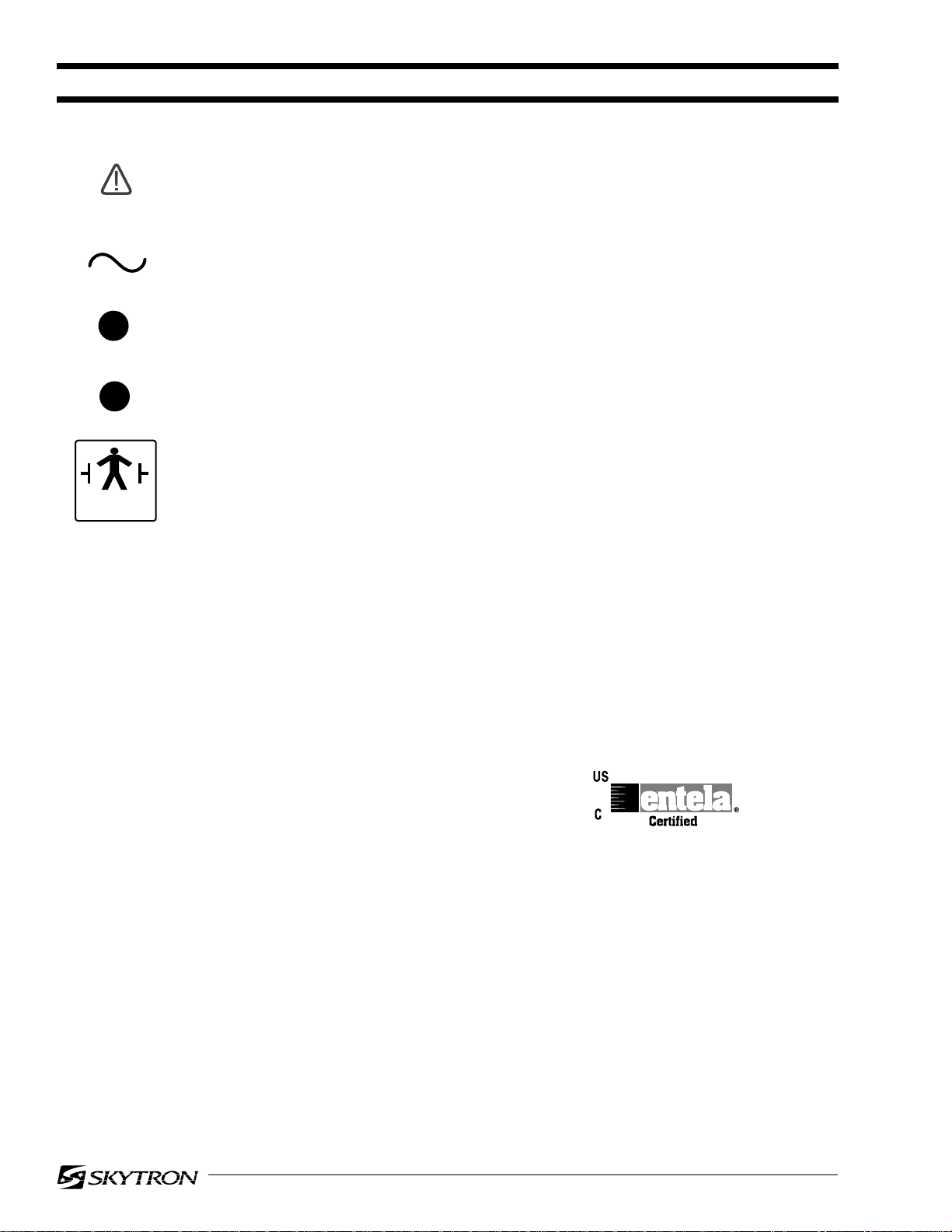
ATTENTION, CONSULT MANUAL FOR FURTHER INSTRUCTIONS.
INDICATES SPECIAL USER ATTENTION.
AC VOLTAGE
3A
5A
TYPE B
EQUIPMENT
FUSE TYPE 3 AMP, SLOW BLOW TYPE
FUSE TYPE 5 AMP, SLOW BLOW TYPE
CLASS I DEFIBRILLATION PROOF, TYPE B EQUIPMENT- IPX4 RATED.
INTERNALLY POWERED EQUIPMENT
FOR DRY LOCATIONS
UNIT TO BE USED ONLY IN SPECIFIED ENVIRONMENTAL CONDITIONS
TEMPERATURE: 15˚ - 30˚ C (60˚ -85˚ F)
HUMIDITY: 30% - 60% RELATIVE HUMIDITY, NON CONDENSING
ENTELA CERTIFIED
TO UL2601-1
CAN/CSA601.1, IEC 60601-2-46
RECOMMENDED TOOL LIST
1 PIN PUNCH SET 1/8" - 3/8"
1 TEFLON TYPE SPRAY LUBRICANT (TRI-FLOW)
1 SET OF PHILLIPS SCREWDRIVERS
1 SET OF FLAT BLADE SCREWDRIVERS
1 DIGITAL LEVEL
1 METRIC, L-TYPE ALLEN WRENCH SET 1.5-8mm
1 PENCIL
1 TRUE RMS VOLTMETER
1 SET OF NON ABRASIVE CLEAN CLOTHS
1 MILD CLEANING AGENT, NON ALCOHOL
Page 5

1-1. General
SECTION I MAINTENANCE
Page 3
To ensure proper operation and extend the life of
your SKYTRON surgical lighting fixture, the following preventive maintenance procedures are recommended.
NOTE
All repairs should be made using authorized SKYTRON replacement parts.
1-2. Daily Maintenance
Daily or between cases, the lighthead exterior
should be wiped down with a mild cleaning agent
which will not affect the painted or acrylic parts.
•Avoid the use of cleaning solutions which contain
high concentrations of alcohol, ethelene glycol,
phenol, iodophors, or glutaraldehyde based disinfectants. Some degree of staining, pitting, and
discoloration may occur if these are used.
b. Check the focus drive mechanism for proper
operation and lubrication. Lubricate the drive
gears with lithium grease and all pivot points with a
lightweight oil as necessary.
c. The filter/diffuser assemblies should be removed and dusted with a clean cloth or washed
and air dried as a complete assembly. Use
plexiglass cleaners, DO NOT use alcohol based
cleaners on the acrylic diffusers.
d. All attaching hardware (screws, nuts, etc.)
should be physically checked for tightness. Any
missing hardware MUST be replaced.
WARNING
Apply LOC-TITE to any replacement or
loose vertical support tube attaching
screws.
Always consult with the manufacturer of the cleaning agent for proper application and use. Always
spot test on an inconspicuous area before use.
•Avoid personal injury. Do not attempt to clean
lighthead unless power is turned off at wall control
and fixture has sufficiently cooled.
•Avoid using excessive amounts of spray cleaners
near top cover vents. Leakage of fluids into the
interior of lighthead may cause corrosion of electrical components.
•Periodically the filter/diffuser assemblies should
be removed and dusted with a clean cloth or
washed and air dried as a complete assembly.
•DO NOT operate lights without the filter/diffuser
assemblies in place.
•Use plexiglass cleaners, DO NOT use alcohol
based cleaners on the acrylic diffusers.
1-3. Preventive Maintenance Procedures
The following procedures should be done semiannually or sooner as needed.
a. Lighthead top cover should be removed and
any accumulation of dust or lint removed.
e. Rotate the radial arm assemblies around the
ceiling mount to check the slip ring/brush block
assemblies. With electrical power "ON", if the
lights become intermittent or go out, check and
repair or replace the brush block or slip ring as
necessary.
f. Check the remaining slip ring/brush block
assemblies by raising, lowering, and rotating the
lighthead through its full range of motion. With
electrical power "ON", if the lights become intermittent or go out, check and repair or replace the
appropriate brush block or slip ring as necessary.
g. Check all fixture rotation axes for proper
adjustment. Adjust as necessary using applicable
adjustment procedures from the adjustment section of this manual (Section 2).
h. Check light bulb voltages to ensure maximum bulb life.
1-4. Bulb Changing
Since SKYTRON Surgical Lights contain multiple
bulbs, it would not normally be necessary to change
a burned out bulb during a surgical procedure. The
loss of one or even three bulbs in a large diameter
lighthead may be completely unnoticed during
use.
Page 6
Page 4
To replace a bulb, use the following procedure:
WARNING
Be sure the power is turned "OFF" and
the bulb has cooled before changing.
1/4 TURN
SCREW
NOTE
Halogen bulbs are sensitive to body
oils. DO NOT handle the glass surface
of bulb as body oil from your fingers can
create a "hot spot" and may cause the
bulb to burn out prematurely.
NOTE
To ensure proper operation of your Stellar Light, use ONLY Skytron replacement bulbs Part Number B1-010-28.
Figure 1-1.
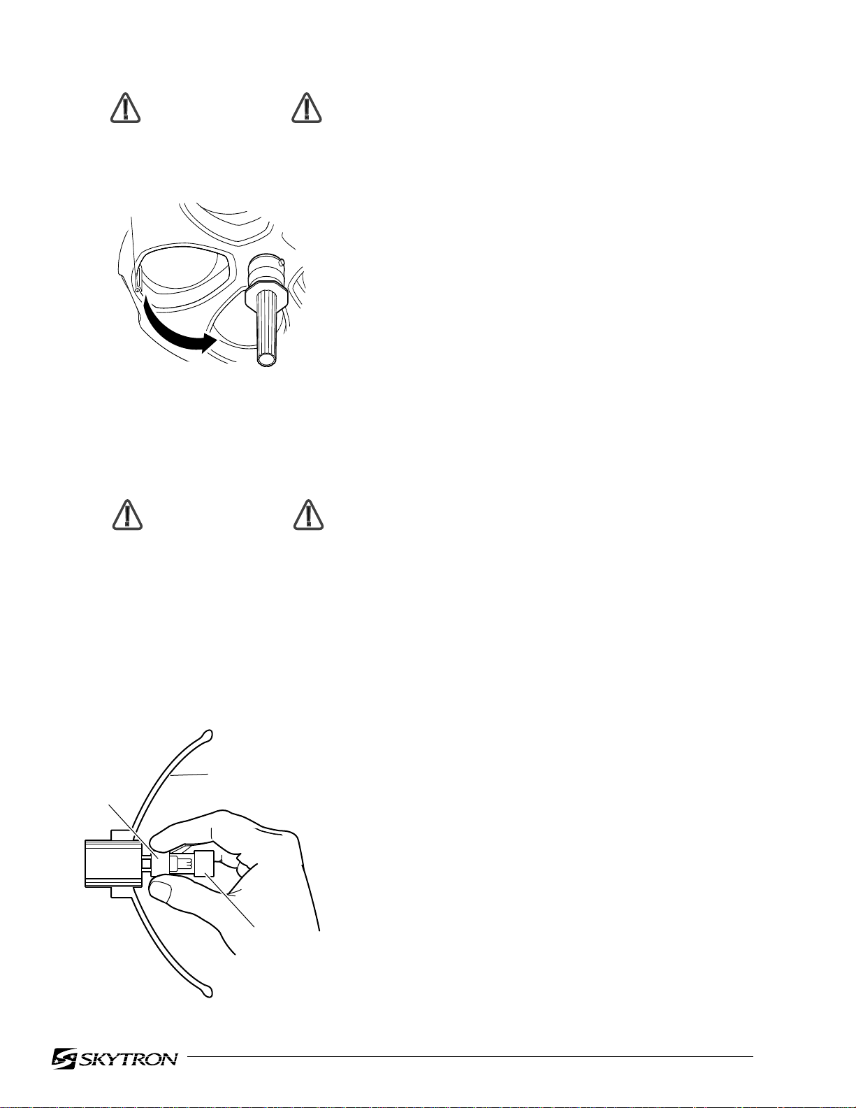
a. Hold the diffuser/filter assembly with one
hand, loosen the "1/4-turn" screw and lower the
diffuser/filter assembly. See figure 1-1.
WARNING
DO NOT attempt to remove the bulb by
pulling on the glass surface or end cap.
This may cause the bulb to break off in
your hand.
b. Using caution not to touch the reflector
surface, hold the bulb by the base and pull it out.
See figure 1-2. Slightly working the bulb back and
forth may aid in bulb removal.
REFLECTOR
SURFACE
BASE
c. Holding the replacement bulb by the base,
plug it directly into the socket. Do not touch the
glass portion of the bulb reflector surface with your
fingers. This can best be done by using the plastic
wrapper that the bulb is packaged in, or a clean
cloth wrapped around the base of the bulb when
installing. Be sure bulb base is properly seated in
the connector to insure proper focus alignment.
NOTE
To extend the life of the bulb reflector
surface, it should NOT be included in
normal cleaning. It should be cleaned
only if absolutely necessary. Clean
gently with a clean, damp, soft cloth
and a mild soap solution. NO abrasives.
d. Replace the filter/diffuser assembly by placing the tab into the slot in the lighthead face. Place
the assembly in position and secure with 1/4-turn
screw.
Figure 1-2.
END
CAP
NOTE
Amount of voltage applied to the bulb
will affect bulb life. Over voltage will
cause the bulbs to burn out prematurely. Proper applied voltage (to the
lighthead) should be 20V ± 0.2V.
Page 7
1-5. Focus Adjustment
JAM NUT
ADJUSTMENT
SCREW
FOCUS
ROD
As part of normal Preventive Maintenance, the
lighthead focus adjustment should be checked. If
an adjustment is necessary, use the following procedures:
a. Remove all filter/diffuser assemblies. Check all
bulbs to make sure the bulb base is flat and securely
seated in the connector. Remove the lighthead top
cover screws and remove the top cover.
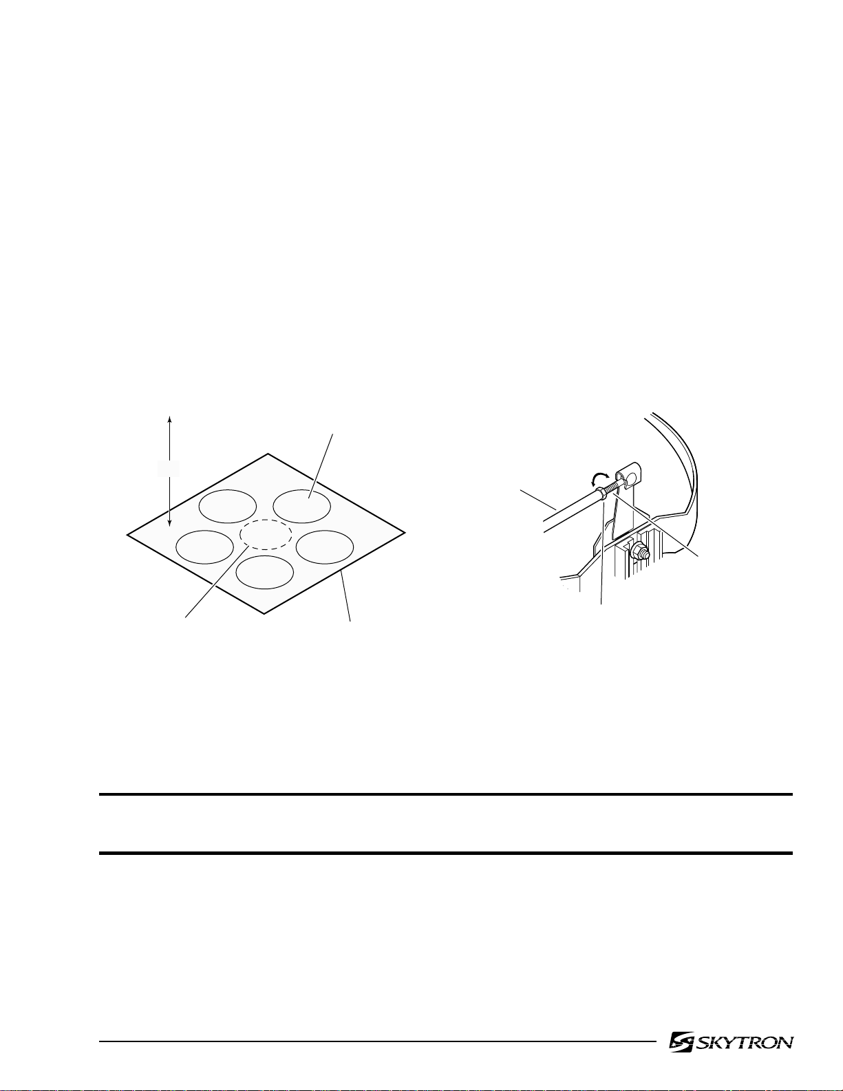
b. Position the lighthead 42" from a white test
surface. Turn main power "ON" and set intensity on
low. Adjust focus control to widest pattern diameter
so each bulb can be seen individually. See figure
1-3.
Page 5
c. Adjust the focus control to check that all bulb
patterns will converge on a single spot anywhere
from two to six feet from lighthead face.
d. To adjust a misaligned bulb holder, loosen the
jam nut on the affected focus rod and turn the
adjustment screw as needed to achieve proper
alignment. See figure 1-4.
e. Install filter/diffuser assemblies and top cover
when adjustments are complete.
LIGHTHEAD
42"
BULB
CONVERGENCE
Figure 1-3.
INDIVIDUAL
BULB SPOT
TEST
SURFACE
Figure 1-4.
WARNING
Do not remove lighthead when support arm is in down position. The balance mechanism will be
severely damaged.
Page 8
Page 6
SECTION II POSITIONING AXES ADJUSTMENT
2-1. General
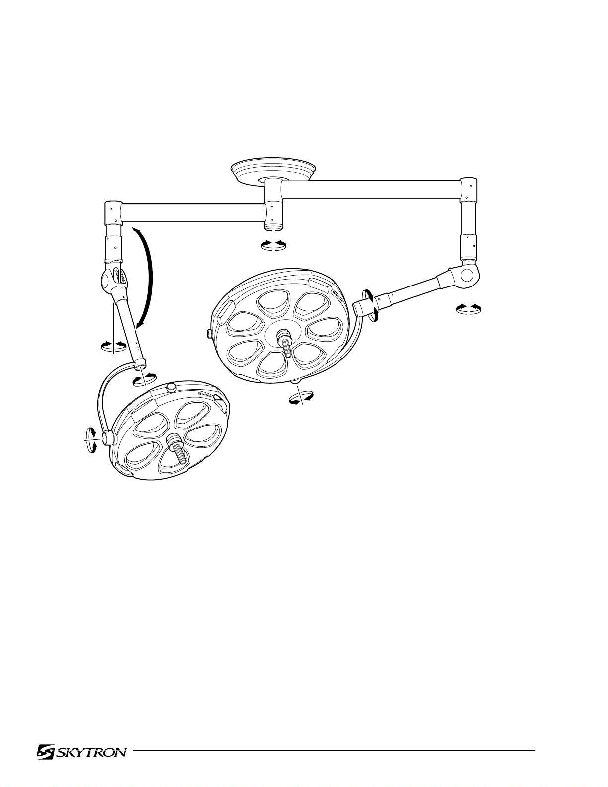
As a part of normal preventive maintenance, all fixture rotation axes adjustments should be checked
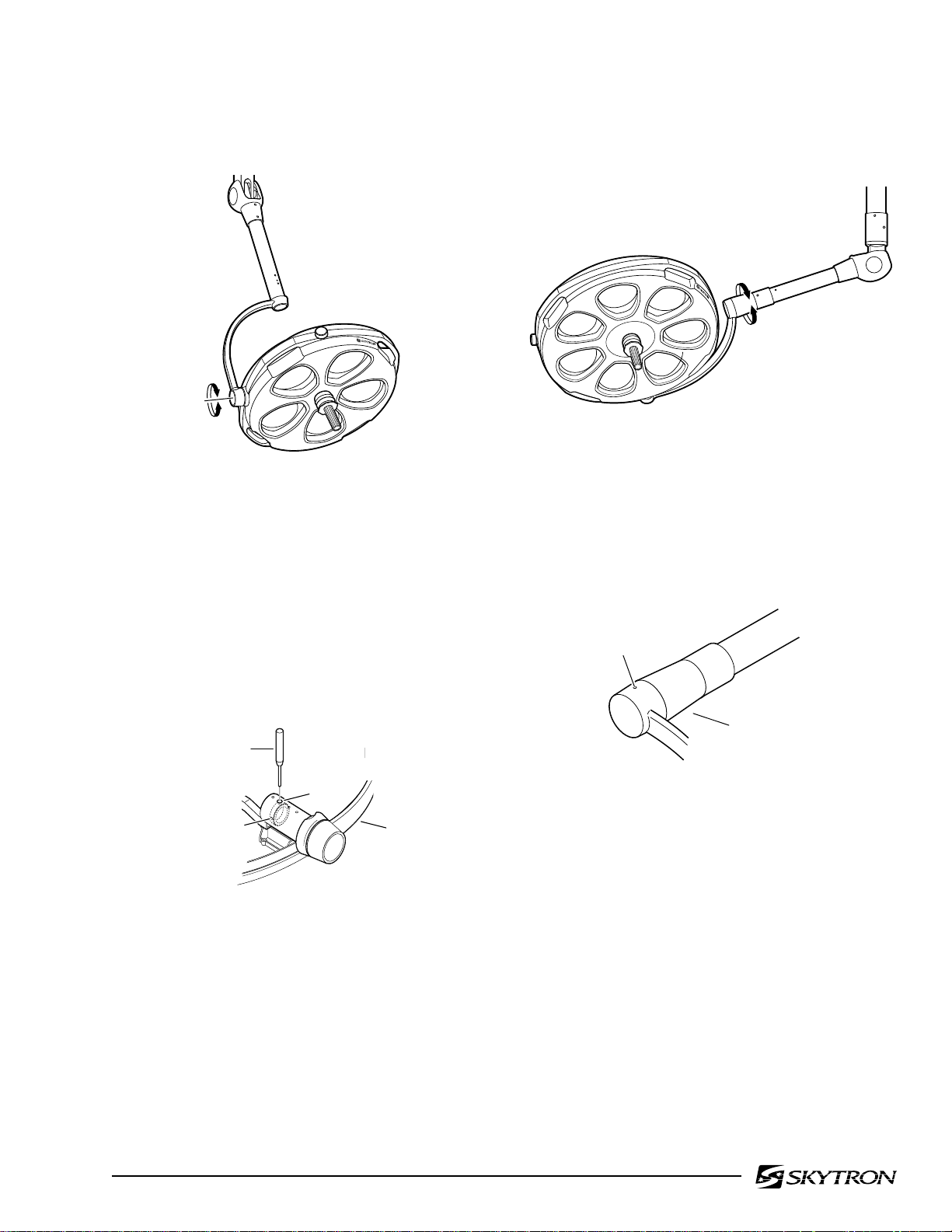
and adjusted as necessary. Refer to figure 2-1 for location of desired check or adjustment procedure.
E
C
D
B
A
A- Lighthead Pitch Axis paragraph 2-2
B- Lighthead Roll Axis-
•Model 29 lighthead paragraph 2-3
•Model 23 lighthead paragraph 2-4
B
A
D
C- Vertical Travel Tension paragraph 2-5
D- Lighthead Horizontal
Rotation paragraph 2-6
E-Radial Arm Horizontal
Rotation paragraph 2-7
Figure 2-1. Fixture Rotation Axis
Page 9
2-2. Lighthead Pitch Adjustment
Page 7
2-3. Model 29 Lighthead Roll Adjustment
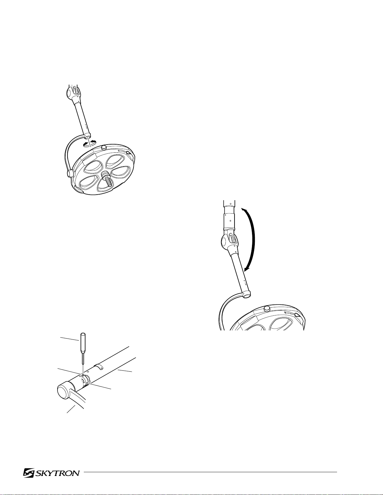
a. Check the pitch axis tension of each lighthead
by moving it through its full range of motion. See
figure 2-2.
A
Figure 2-2. Lighthead Pitch
b. The lighthead should move freely yet maintain its position without drifting. If an adjustment is
required, remove the top cover, refer to figure 2-3
and proceed as follows:
c. Rotate the lighthead until an allen set screw
is visible through the adjustment hole. Loosen the
set screw, rotate the lighthead 180° and loosen the
second set screw.
a. Check the roll axis tension of the model 29
lighthead by moving it through its full 360° range of
travel. See figure 2-4.
B
Figure 2-4. Model 29 Lighthead Roll
b. The lighthead should move freely yet maintain its position without drifting. If the lighthead
drifts, refer to figure 2-5 and proceed as follows:
ADJUSTMENT
HOLE
PIN PUNCH
HOLE
SET
SCREW (2)
YOKE
Figure 2-3. Lighthead Pitch Adjustment
d. Rotate the lighthead until a hole is visible and
insert a pin punch into the hole in the adjustment
nut.
e. With the nut held captive with the pin punch,
rotate the lighthead clockwise to increase the friction or counterclockwise to decrease the friction.
f. Remove pin punch and check adjustment.
Tighten set screws and replace top cover when
adjustment is complete.
YOKE
Figure 2-5. Model 29 Roll Adjustment
c. Rotate the yoke until an allen set screw is
visible through the adjustment hole and loosen the
set screw.
d. Continue to rotate the yoke until a 5mm hole
is visible through the hole. Insert a pin punch into
the hole in the adjustment nut.
e. With the tension nut held captive with the pin
punch, rotate the yoke clockwise (viewed from the
front) to increase the friction and counterclockwise
to decrease the friction.
f. Remove pin punch and check the lighthead for
proper tension. Repeat adjustment procedure if
necessary. After the adjustment is correct, be sure
to tighten the set screw
Page 10
Page 8
2-4. Model 23 Lighthead Roll Adjustment
a. Check the roll axis tension of the model 23
lighthead by moving it through its full 360° range of
travel. See figure 2-6.
B
Figure 2-6. Model 23 Lighthead Roll
d. Continue to rotate the yoke until a 5mm hole
is visible through the hole. Insert a pin punch into
the hole in the adjustment nut.
e. With the tension nut held captive with the pin
punch, rotate the yoke clockwise (viewed from the
front) to increase the friction and counterclockwise
to decrease the friction.
f. Remove pin punch and check the lighthead for
proper tension. Repeat adjustment procedure if
necessary. After the adjustment is correct, be sure
to tighten the set screws.
2-5. Vertical Travel Tension Adjustment
a. Check the adjustment of the Balance Mechanism for its capacity to support the lighthead throughout its range of vertical motion. See figure 2-8.
b. The lighthead should move freely yet maintain its position without drifting. If an adjustment is
required, refer to figure 2-7 and proceed as follows:
c. Rotate the yoke until an allen set screw is
visible through the adjustment hole and loosen the
set screw. Rotate the yoke 180° and loosen the
second set screw.
PIN
PUNCH
HOLE
SET SCREW (2)
YOKE
SUPPORT
ARM
Figure 2-7. Model 23 Roll Adjustment
C
Figure 2-8. Lighthead Vertical Travel
b. The lighthead should move freely yet maintain its selected position within the range of motion
without drifting. If an adjustment is necessary,
refer to figure 2-9, and proceed as follows.
c. Remove two screws securing the cover plate
and remove the cover plate from the Horizontal
Support Arm.
d. Pull the lighthead downward until the adjustment nut is visible through the adjustment slot in
the support arm.
Page 11
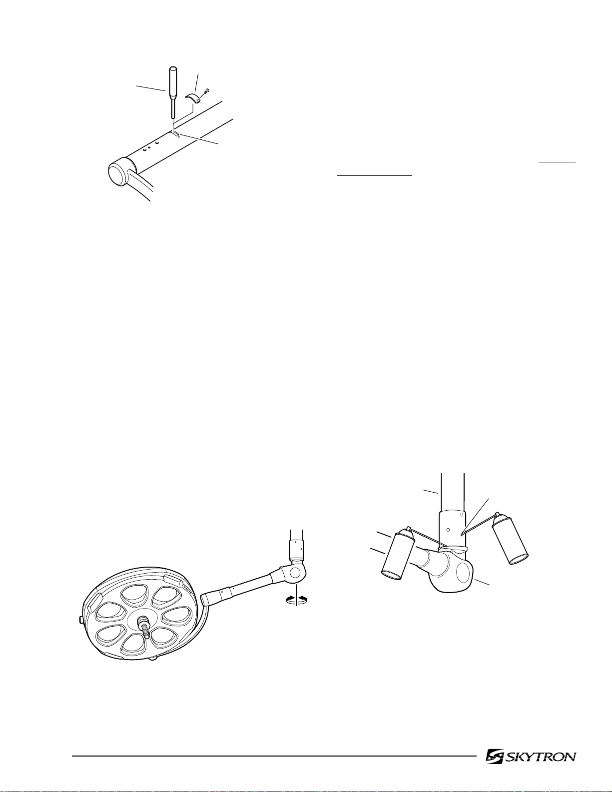
PIN
PUNCH
COVER
PLATE
ADJUSTMENT
SLOT
Page 9
b. The lighthead should maintain its position
without drifting, yet move freely around the Balance Mechanism. Normally this adjustment is
correct from the factory and does not change. If the
lighthead drifts, the most likely cause is an unlevel
mounting plate.
Figure 2-9. Vertical Travel Adjustment
e. Insert a pin punch through the adjustment slot
and into a hole of the spring tension adjustment
nut. Using the pin punch, turn the adjustment nut
clockwise to increase the tension, counterclockwise to decrease the tension.
f. Remove the pin punch, check and repeat
adjustment procedure as necessary to achieve
proper spring tension. The lighthead should be
able to hold its position at any angle from the VST.
g. Reinstall cover plate on the Horizontal Support Arm.
2-6. Horizontal Rotation Axis Adjustment
a. Check horizontal rotation axis adjustment by
moving the lighthead through its full range of travel
around the Balance Mechanism. See figure 2-10.
NOTE
•Recheck the mounting plate to make
sure it is absolutely level. In most
cases, releveling the mounting plate
will solve any drifting problems.
•If the lighthead sticks or is difficult to
move, before making any adjustments,
lubricate the BOM needle bearings with
a Teflon type spray lubricant such as
TRI-FLOW (available from RichardsonVicks, Inc., Memphis, TN) or equivalent. See figure 2-11. After spraying,
rotate the lighthead several times in
both directions and recheck for proper
tension.
VST
ADJUSTMENT
HOLE
Figure 2-10. Horizontal Rotation
BOM
D
Figure 2-11 . BOM Lubrication
Page 12
Page 10
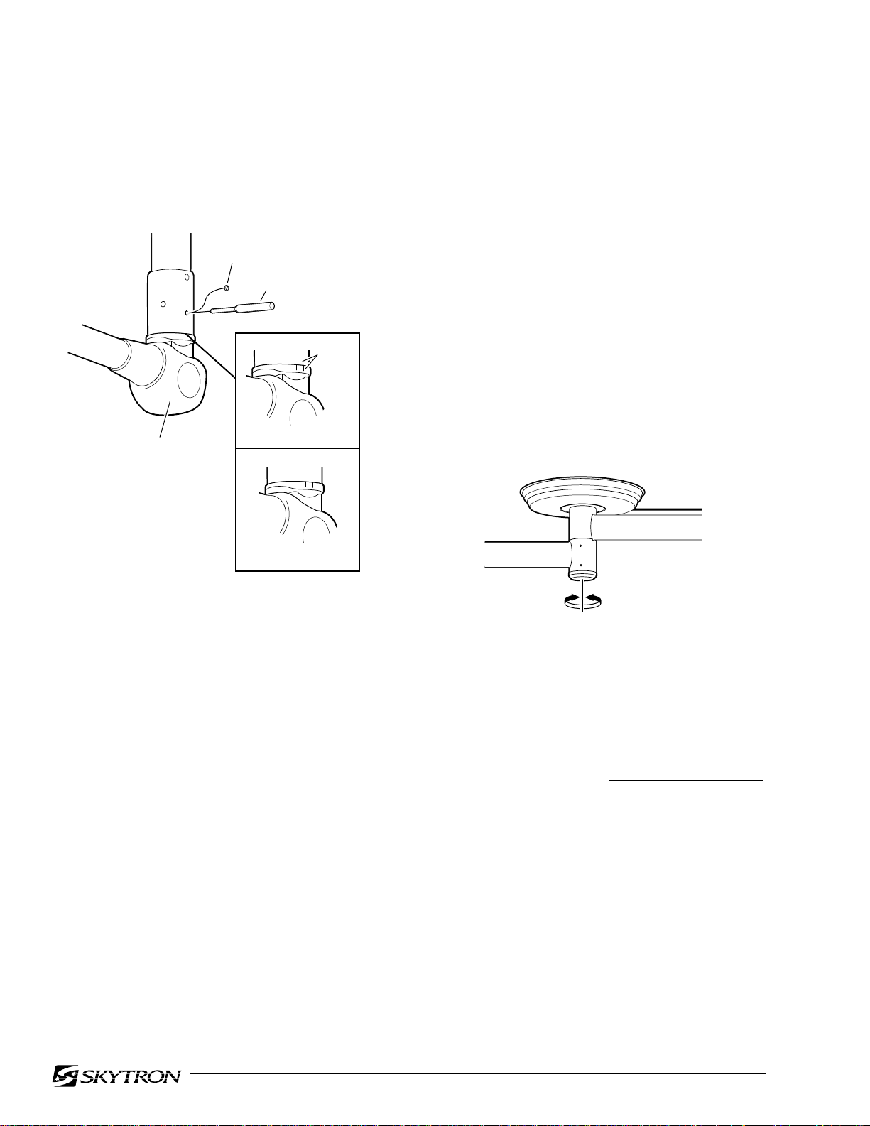
c. If releveling the mounting plate or lubricating
the BOM needle bearings does not correct the
problem, an adjustment may be required. This
adjustment is made by increasing or decreasing
the bearing preload. Refer to figure 2-12 and
proceed as follows:
CHROME
PLUG
PIN
PUNCH
PENCIL
MARKS
BOM
BEFORE
h. With the nut held captive by the pin punch,
rotate the lighthead so that the pencil marks are
approximately 1/8" apart. Turn the lighthead clockwise (viewed from the bottom) to increase the
tension and counterclockwise to decrease the tension. In some cases it may require considerable
force on the lighthead to make this adjustment.
i. Remove the pin punch and check the lighthead
for proper tension. Repeat adjustment procedure
if necessary. When proper adjustment has been
achieved, tighten the set screws and install the
chrome plug.
2-7. Radial Arm Horizontal Rotation Axis
a. Check the horizontal rotation axis tension by
moving the Radial Arms through their full range of
travel around the center mounting hub. Refer to
figure 2-13.
AFTER
Figure 2-12. Horizontal Rotation Adjustment
d. Locate the adjustment hole. This hole is
located just beneath the lower VST screws in the
BOM and has a slotted head chrome plug in it.
e. Remove the chrome plug, rotate the lighthead
around the Balance Mechanism until any set screws are
visible through the adjustment hole and loosen them.
f. Continue to rotate the lighthead until a hole in
the nut is visible through the adjustment hole.
Insert a pin punch through the adjustment hole and
into the hole in the nut.
g. To determine the amount of adjustment,
rotate the lighthead so the pin punch is touching
one side of the adjustment hole and use a pencil to
mark a reference line as shown in figure 2-12.
Rotate the lighthead so the pin punch is touching
the other side of the adjustment hole and mark
another reference line as shown in figure 2-12.
E
Figure 2-13.
b. The Radial Arms should maintain their position without drifting yet move freely around the hub.
Normally this adjustment is correct from the factory
and does not change. If the Radial Arms drift, the
most probable cause is an
unlevel mounting plate.
NOTE
Recheck the mounting plate to make
sure it is absolutely level. In most cases
releveling the plate will solve any drifting problem.
c. If releveling the mounting plate does not
correct the drift, or the Radial Arms are difficult to
move, the bearing preload must be adjusted. This
requires the use of special tools. Contact your
SKYTRON dealer for assistance.
Page 13
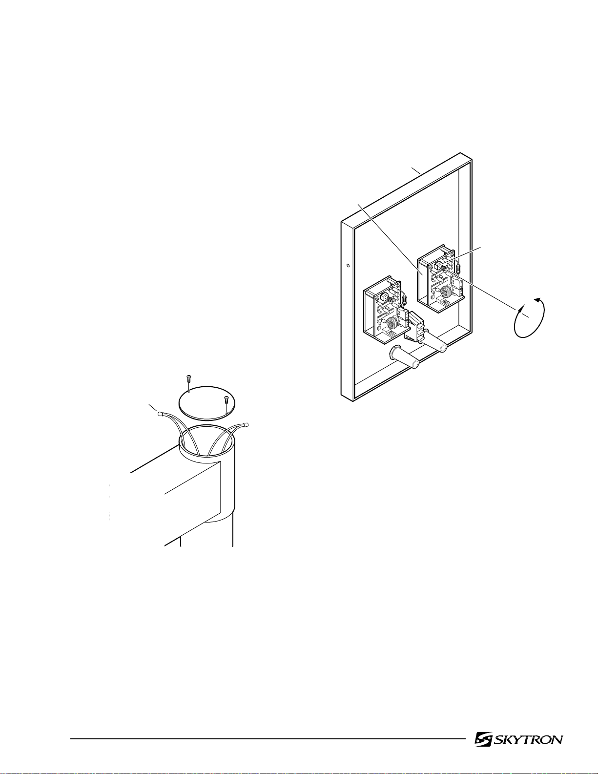
2-8. Bulb Voltage Adjustment
DECREASE
VOLTAGE
INCREASE
VOLTAGE
DIMMER
CONTROL
VOLTAGE
ADJUSTER
WALL CONTROL
FRONT PANEL
To insure maximum intensity and to prolong bulb
life, the voltage applied to the lighthead should be
20VAC ± 0.2V. Use the following procedures to
test and adjust the bulb applied voltage.
NOTE
The internal circuitry used in the Stellar
system requires the use of a true RMS
type digital voltmeter to accurately
set the bulb voltage. Premature bulb
failure will result from incorrect voltage
a. Remove top cover from VST end of radial arm
and test bulb voltage at the wire connections. Turn
main power "ON" and set the Dimmer Control for
the lighthead being tested to maximum intensity for
the test. Output voltage (at the connectors) should
be 20V ± 0.2V. See figure 2-14.
Page 11
b. Adjust the voltage to the lighthead by turning
the adjuster on the back of the appropriate dimmer
control in the wall control. See figure 2-15.
WIRE
CONNECTION
Figure 2-14. Bulb Voltage Test
Figure 2-15. Voltage Adjustment
c. Turn the adjuster clockwise to increase the
output voltage, counterclockwise to decrease the
voltage. Proper voltage at the connectors should
be 20V ± 0.2V.
Service
Preventative maintenance performed by SKYTRON
factory trained service representatives, using authorized parts and service techniques, will assure
the extended and reliable performance of your
SKYTRON Surgical Light.
For factory service contact your nearest SKYTRON
dealer or write: SKYTRON, 5000 - 36th St., S.E.,
Grand Rapids, MI 49512 / Phone (616) 957-0500.
Page 14
Page 12
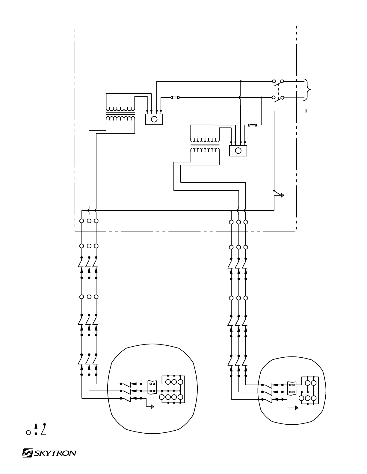
T-1 390W
TRANSFORMER
WIRING DIAGRAM
FUSE
SB5A
DIMMER
CONTROL
T-2 270W
TRANSFORMER
DIMMER
CONTROL
FUSE
SB3A
MAIN
POWER
SWITCH
INPUT
120VAC
- TERMINAL STRIPTS
- SUPPORT ARMSA
- RADIAL ARM ASSEMBLYRAA
- CRIMP CONNECTORS
- BRUSH BLOCK
- SLIP RING
RAA
- VERTICAL SUPPORT TUBEVST
T1-T3 - TRANSFORMER
VSTSA
L1-L8 - BULB
29
LIGHTHEAD
TS
L5L6L7
L1L2L3
MODEL ST2923
RAA
VSTSA
23
LIGHTHEAD
L4
TS
L4
L1L2L3
L5
Page 15

Page 16

Grand Rapids, MI 49512 • 616.656.2900 • FAX 616.656.2906
5085 Corporate Exchange Blvd. S.E.
 Loading...