

Page 1
SURGICAL TABLE
MAINTENANCE MANUAL
MODEL 6700 Series HERCULES
TEC-D-0018 REV0
8/09
Page 2

Page 3

Page 1
TABLE OF CONTENTS
Title Page
BASIC RECOMMENDED TOOLS & MAINTENANCE PROCEDURES ................................................... 3
EQUIPMENT LABELS .............................................................................................................................. 4
6700 Series Hercules General Purpose Surgical Table Specifications .................................................... 5
SECTION I HYDRAULIC SYSTEM ......................................................................................................... 6
1-1. General ......................................................................................................................................... 6
1-2. Component Operation ................................................................................................................... 7
a. Motor/Pump Operation ............................................................................................................. 7
b. Pressure Relief Valve ................................................................................................................ 7
c. Mini-Valves ................................................................................................................................ 8
d. Hydraulic Cylinders (Slave Cylinders) ..................................................................................... 10
e. Elevation Cylinder Return Circuit ............................................................................................ 12
f. Brake System .......................................................................................................................... 12
g. Emergency Brake Release ..................................................................................................... 13
h. Flex/Reflex System .................................................................................................................. 13
1-3. Hydraulic Adjustments ................................................................................................................ 14
a. Fluid Level ............................................................................................................................... 14
b. Bleeding The Hydraulic System .............................................................................................. 14
c. Pressure Relief Valve .............................................................................................................. 14
d. Speed Controls ....................................................................................................................... 15
SECTION II MECHANICAL TABLE ADJUSTMENTS ............................................................................ 16
2-1. Back Section Gear Mesh Adjustment.......................................................................................... 16
2-2. Hydraulic Cylinder Adjustment .................................................................................................... 16
a. Back Section ........................................................................................................................... 16
b. Leg Section ............................................................................................................................. 16
2-3. Head Section Adjustment ............................................................................................................ 17
2-4. Trendelenburg Cap Bolt Torque Procedure .................................................................................. 17
2-5. Side Rails ..................................................................................................................................... 18
2-6. Casters ......................................................................................................................................... 18
SECTION III HYDRAULIC TROUBLESHOOTING ................................................................................ 19
3-1. Precautions ................................................................................................................................. 19
3-2. Troubleshooting Notes ................................................................................................................. 19
3-3. ELEVATION DIAGNOSIS CHART ............................................................................................... 20
3-4. TRENDELENBURG DIAGNOSIS CHART .................................................................................. 21
3-5. LATERAL - TILT DIAGNOSIS CHART ........................................................................................ 22
3-6. FLEX SYSTEM DIAGNOSIS CHART .......................................................................................... 23
3-7. BACK SECTION DIAGNOSIS CHART ........................................................................................ 24
3-8. LEG SECTION DIAGNOSIS CHART ........................................................................................... 25
3-9. KIDNEY LIFT DIAGNOSIS CHART ............................................................................................ 26
Although current at the time of publication, SKYTRON'S policy of continuous development makes this
manual subject to change without notice.
Page 4

Page 2
TABLE OF CONTENTS (continued)
Title Page
3-10. BRAKE CIRCUIT DIAGNOSIS CHART ...................................................................................... 27
3-11. Flexible Hose Identification and Placement ................................................................................ 28
3-12. Kidney Lift System........................................................................................................................ 29
SECTION IV ELECTRICAL SYSTEM ................................................................................................... 31
4-1. General ....................................................................................................................................... 32
4-2. Components ................................................................................................................................ 32
SECTION V ELECTRICAL TROUBLESHOOTING ................................................................................ 33
5-1. General ....................................................................................................................................... 33
5-2. Troubleshooting Notes .................................................................................................................. 33
5-3. Main Switch ................................................................................................................................. 33
5-4. Batteries ...................................................................................................................................... 34
5-5. Capacitor / Rectifier / AC 120V Transformer ............................................................................... 35
5-6. Pendant Control .......................................................................................................................... 36
5-7. Auxiliary Switches ....................................................................................................................... 38
5-8. Relay Box .................................................................................................................................... 39
5-9. Main Wire Harness Continuity Tests ............................................................................................ 41
5-10. Solenoids .................................................................................................................................... 42
5-11. Motor/Pump Assembly ................................................................................................................ 43
5-12. Return-to-Level / Positioning Inhibit Micro-Switches .................................................................... 44
5-13. Micro-Switch Troubleshooting ....................................................................................................... 45
APPENDIX ............................................................................................................................................. 52
Maintenance Matrix ...................................................................................................................... 52
WARNING
Indicates a possibility of personal injury.
CAUTION
Indicates a possibility of damage to
equipment.
Indicates important facts or helpful hints.
NOTE
Page 5

Page 3
BASIC RECOMMENDED TOOLS:
1/8". 1/4" STRAIGHT BLADE SCREWDRIVERS
#2 PHILLIPS SCREWDRIVER
HYDRAULIC PRESSURE GAUGE SKYTRON P.N. 6-050-02
METRIC ALLEN® WRENCHES 1.5mm-8mm
ADJUSTABLE CRESCENT WRENCH
DIGITAL VOLTMETER, TRUE RMS
METRIC OPEN END WRENCHES 7mm-18mm
LEVEL (CARPENTERS)
BASIC RECOMMENDED MAINTENANCE PROCEDURES
The specific items listed in the MODEL 6701 SERIES MAINTENANCE MATRIX (Appendix) and the basic
items below shall be inspected and repaired or replaced as necessary. The suggested time intervals are
intended as a guideline only and actual maintenance will vary by use and conditions. For optimal usage,
safety and longevity of the product, have it serviced only by an authorized Skytron representative with
authentic Skytron replacement parts.
• Check All Table Functions
• Lubricate Elevation Slider Assembly with Mobilux EP (Extreme Pressure) Grease P/N D6-010-89-1
• Tighten X-Ray Top Stand-Offs, Use Blue Loc-Tite
Only facility-authorized SKYTRON trained, maintenance personnel should troubleshoot the
SKYTRON 6700 Series Surgical Table. Trouble shooting by unauthorized personnel could
result in personal injury or equipment damage.
How to contact us:
Skytron
5085 Corporate Exchange Blvd. SE, Grand Rapids, MI 49512
PH: 1-800-759-8766 (SKY-TRON)
FAX: 616-656-2906
Page 6
Page 4
DO NOT SIT ON END OF LEG SECTION(S) AS LOADS
IN EXCESS OF 140 LBS, MAY CAUSE INSTABILITY
THAT COULD CAUSE THE TABLE TO BE TIPPED OVER.
WARNING
WARNING
USE HEAD SECTION AS FOOT EXTENSION
ONLY - WHEN REVERSING PATIENT ON TABLE
REFER TO OPERATOR MANUAL.
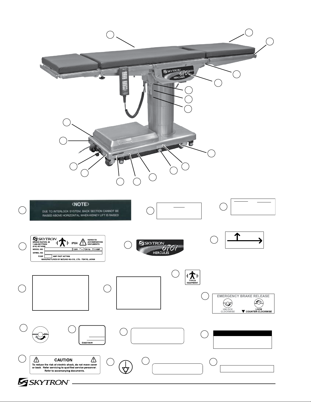
6700 SERIES EQUIPMENT LABELS
18
17
16
15
14
13
12
11
10
9
8
7
6
5
4
3
2
1
18
17
16
15
14
13
12
11
10
9
87
6
5
4
3
2
1
TOP
ROTATION
HAND
LE
ALWAYS LOCK THE TABLE TOP IN POSITION AFTER A FULL
ROTATION OF
180°
DO NOT ROTATE THE TOP WITH AN
UNDISTRIBUTED
PATIENT LOAD AS
INSTABILITY MAY
RESULT,
EXERCISE CAUTION
WITH THE TABLE TOP ROTATED
90°
TO THE
BASE SINCE
AN
IMPROPERLY
DISTRIBUTED
PATIENT LOAD MAY CAUSE THE TABLE TO BE TIPPED
OVER.
TABLE TOP
---------- WARNING ----------
Table Capacity:
Lift
12
00 lbs.
Articulate 10
00 lbs.
See Operators
Manual for Limitations.
POSSIBL
E E
XPLOSION
HAZARD
IF USED IN THE PRESENCE OF
FLAMMABLE ANESTHETICS.
DANGER
THIS PRODUCT COMPLIES WITH RADIATION PERFORMANCE STANDARD 21 CFR
AT THE TIME OF MANUFACTURE
Manufactured:
Model No.
DANGER - E
XPLOS
ION
H
AZARD.
DO
NOT USE IN
T
HE
PRESENCE OF
FLA
MMAB
LE
ANAE
STHETICS
DANGER - RISQUE
D'E
XPL
OSION. NE
PAS
EMPLOYER EN
PRE
SENCE
D'A
NESTHESIQUES
INFLAMMABLES
Grounding
reliability can only be a
chiev
ed w
hen
the equip
ment is connected t
o an
equivalent
receptacle mar
ked "Hospit
al Only"
or "Hosp
ital Grade"
TWIST TO LOCK OR RELEASE PLUG
D6-032-43
D6-032-47
D6-032-46
D3-067-11 (6700B)
D3-067-31 (6701)
D6-034-18
D6-011-29
D6-067-26
D6-017-05
D6-017-29
D6-011-34
D6-065-24
D6-017-28
D6-065-23
D6-065-22
D6-034-21
D6-065-21
D6-067-27
6700 Series Equipment Labels
Page 7
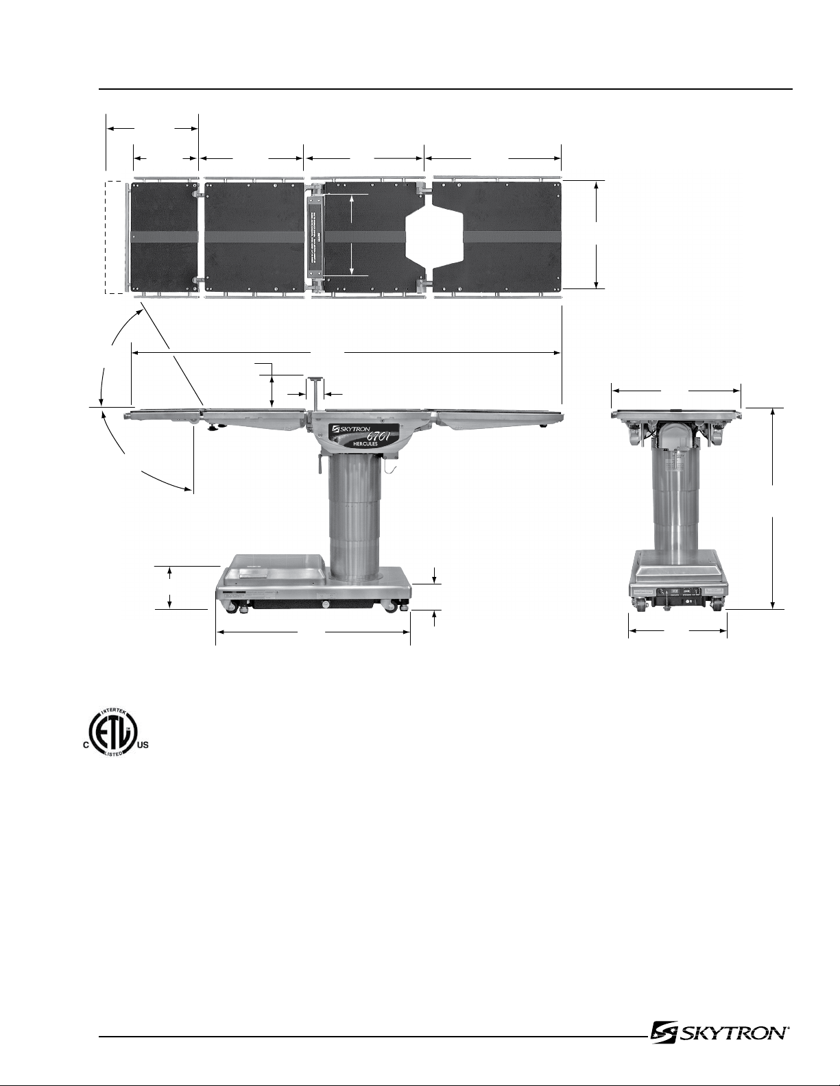
Electrical Specifications
Power requirements
Current Leakage
Power Cord
120 VAC, 60Hz, 450 Watts
Less than 100 micro amps
15 feet w/hospital grade connector (removable)
12-1/2"
19-1/4" 23" 24-1/4"
14-1/2"
19-3/4"
6"
3"
79"
TOP VIEW
90°
60°
14-1/2"
37"
SIDE VIEW
8-1/2"
5-3/4"
19"
22"
41" MAX
23" MIN
END VIEW
UNIT TO BE USED ONLY IN SPECIFIED ENVIRONMENTAL CONDITIONS
CLASS I DEFIBRILLATION PROOF, TYPE B EQUIPMENT- IPX4 RATED.
INTERNALLY POWERED EQUIPMENT
ETL LISTED
CONFORMS TO
UL STD 60601-1
CERTIFIED TO
CAN/CSA STD C22.2 NO.601.1
Page 5
6700 Series Specifications
Page 8
Page 6
ELEV BRAKEKIDNEYLEGBACKFLEXTILTTREND
1
1
2
3
2
2
5
4 2
7 7 9
6 8
4 8
10
10 11
11
12
10
1 3 567 9
11
MOTOR/PUMP
ASSEMBLY
PLUMBING
TERMINAL
ELEVATION
CYLINDER
TRENDELENBURG
CYLINDER
TILT
CYLINDER
BACK SECTION
KIDNEY LIFT
LEG SECTION
PRESSURE
RELIEF VALVE
(4) BRAKE ASSEMBLIES
EMERGENCY
BRAKE RELEASE
MINI-
VALVES
3
4 5
6 7
8 9
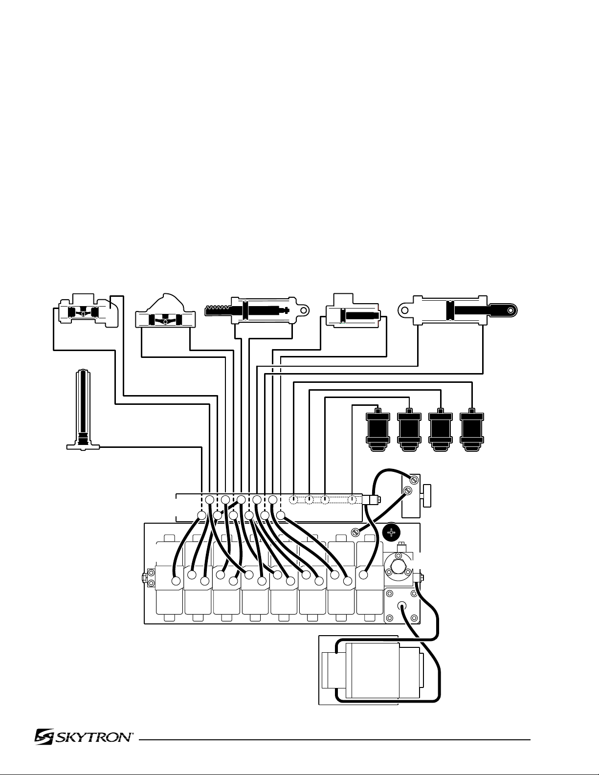
SECTION I HYDRAULIC SYSTEM
1-1. General
Electro-Hydraulic System
The hydraulic system (with the exception of the hydraulic cylinders and hoses) is contained within the
base of the table. The hydraulic valves and pump
are electrically controlled by the use of a hand-held
push button pendant control. The power requirements for the table are 120 VAC, 5 amp, 60 Hz.
The table contains the following components. Refer
to the block diagram (figure 1-1) for relationship.
a. Oil Reservoir - Main oil supply. Approximately
two quarts.
b. Motor/Pump Assembly - A positive displacement gear type pump provides the necessary oil
pressure and volume.
c. Pressure Relief Valve - Provides an alternate
oil path when the hydraulic cylinders reach the end
of their stroke.
d. Electro/Hydraulic Mini-Valve Assemblies -These
direct the fluid to the appropriate hydraulic cylinders.
e. Hydraulic Lines, Fittings, Connections - They
provide a path for the hydraulic oil.
f. Hydraulic Cylinders - They convert the hydraulic
fluid pressure and volume into mechanical motion.
Figure 1-1. Hydraulic Block Diagram
Page 9
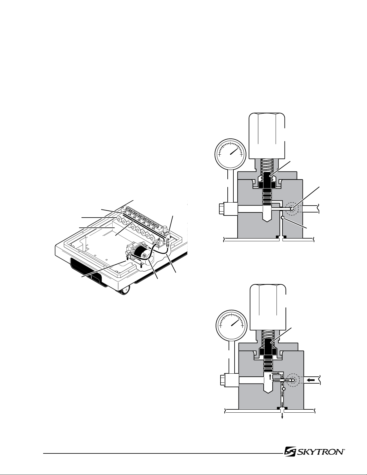
1-2. Component Operation
041905.021mj
MAIN PRESSURE
OIL GALLERY (internal)
MINI-VALVES
OIL RESERVOIR
PUMP
OUTLET
PUMP
INLET
PRESSURE
RELIEF VALVE
MOTOR/PUMP
ASSEMBLY
MAIN RETURN
OIL GALLERY
(internal)
050305.06
PRESSURE RELIEF
ADJUSTMENT NUT
PRESSURE
GAUGE
SPRING
LOADED
PLUNGER
PRESSURE
RETURN
050305.07
PRESSURE RELIEF
ADJUSTMENT NUT
PRESSURE
GAUGE
SPRING
LOADED
PLUNGER
OIL LINE
FROM
PUMP
OIL RESERVOIR
a. Motor/Pump Operation
The motor/pump assembly is a gear type pump that
provides the oil pressure and volume for the entire
hydraulic system. The pump has an inlet side and
an outlet side. The inlet side is connected to the
reservoir which provides the oil supply. The reservoir
has a very fine mesh screen strainer which prevents
foreign material from entering the oil system.
The output line of the pump is connected to the main
oil galley which is internal and common to all the
hydraulic mini-valves and pressure relief valve. Also,
common to the hydraulic mini-valves and pressure
relief valve is an oil galley that internally connects
to the oil reservoir to provide a return path for the
hydraulic oil. See figure 1-2.
Page 7
The main component of the valve is an adjustable
spring loaded plunger that when it is pushed off from
its seat by the oil pressure, the oil flows back into
the reservoir. See figure 1-4. Turning the adjustment
nut clockwise increases the amount of oil pressure
required to open the valve, and turning it counterclockwise decreases the amount of oil pressure.
(See adjustment section for specification.)
Figure 1-2.
b. Pressure Relief Valve
This device provides an alternate oil path back to
the reservoir when the hydraulic cylinders reach
the end of their stroke and the pump continues to
run. If this path were not provided, the pump motor
would stall because the oil cannot be compressed.
The pressure relief valve is directly connected to
the mini-valve bodies and shares both the common
internal main pressure oil galley, and the return
oil galley that internally connects to the reservoir.
See figure 1-3.
Figure 1-3. Pressure Relief Valve Not
Functioning
Figure 1-4. Pressure Relief Valve Functioning
Page 10
Page 8
OIL LINE
BALL
VALVE
OIL LINE
PILOT
PLUNGER
SOLENOID
PISTON
SPOOL
VALVE
OIL RETURN
(RETURN)
OIL GALLERY
(PRESSURE)
SPEED
CONTROL
CHECK
VALVE
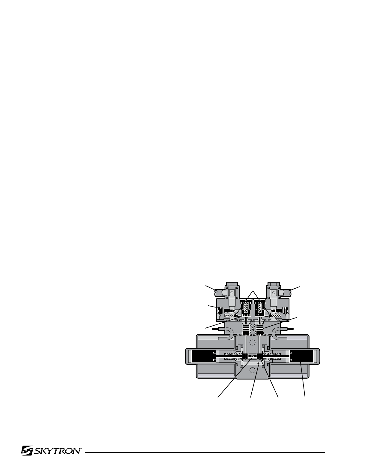
c. Mini-Valves
The operation of the mini-valves is identical for
all table functions except the elevation and brake
circuits. These two hydraulic circuits use a 3-way
(single check valve) type mini-valve. All other
functions use a 4-way (dual check valve) type
mini-valve.
Either type mini-valve is controlled by two pushing
type, electrically operated solenoids. The solenoids
push the spool valve (located in the lower portion of
the valve) one way or the other. This motion opens
the main supply galley (which has pump pressure)
allowing the oil to flow through the various parts of
the mini-valve to the function. The spool valve also
opens an oil return circuit which allows the oil to
return to the oil reservoir.
The main components of the mini-valve and their
functions are listed below:
1. Spool Valve - Opens the main oil galley (pump
pressure) to either mini-valve outlet depending on
which direction the spool valve is pushed. Also it
provides a return path for the oil returning back into
the reservoir.
2. Pilot Plunger - There are two plungers in a
four-way mini-valve (one in a 3-way mini-valve),
one under each check valve. The purpose of the
pilot plungers is to mechanically open the return
check valve allowing the oil to return back into the
reservoir.
the return oil. If the pump puts out more volume
to a slave cylinder than is allowed by the speed
control, the pressure relief valve opens and provides an alternate path for the pump oil to return
to the reservoir.
The following material depicts the three operating
positions of the mini-valve. The movement of the
slave cylinder piston (extend or retract) is determined
by which port of the Mini-Valve is activated.
Mini-Valve in Neutral Position
(No fluid flow) See figure 1-5.
• Spool Valve Centered - This closes off both
oil pressure and oil return galleys.
• Pilot Plungers Both Closed -The pilot plungers control the opening of the check valves. If they
are closed, the check valves must be closed.
• Check Valves - Both check valves are closed
trapping the oil in the cylinder and oil lines.
• Speed Control - When the mini-valve is in the
neutral position, the speed control does not affect
anything.
3. Check Valve - Two are provided in each fourway mini-valve to seal the oil in the cylinders and oil
lines and prevent any movement of the table. One
check valve is provided in a 3-way mini-valve.
4. Speed Controls - There are two speed controls in each 4-way mini-valve. They are needle
valve type controls which restrict the volume of oil
returning back into the reservoir, thereby controlling
the speed of the table surface movement. A 3-way
mini-valve has only one speed adjustment.
The speed controls are always located in the return
oil circuit to allow the movement of the cylinder to
be controlled. Also, by using this control method, it
does not matter what size cylinder and piston is used
because the speed is controlled by restricting
Figure 1-5. Mini-Valve in Neutral Position
Page 11
INLET OUTLET
INLET
OUTLET
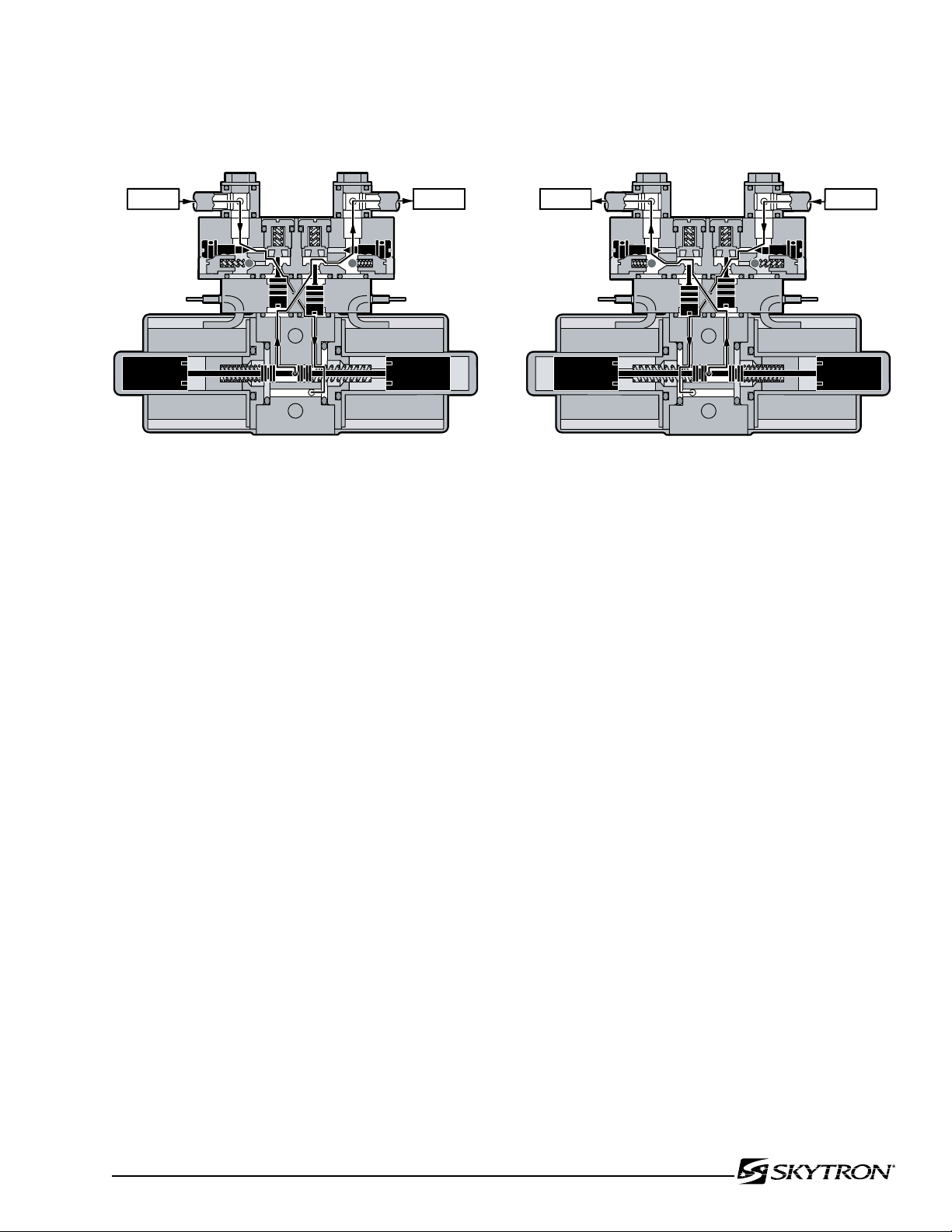
Mini-Valve Right Port Activated
(See figure 1-6)
Page 9
Mini-Valve Left Port Activated
(See figure 1-7.)
Right Mini-Valve Port is Supply Line
Left Mini-Valve Port is Return Line
Figure 1-6. Mini-Valve Right Port Activated
• Spool Valve-Pushed to the left by electric
solenoid. This opens the internal oil pressure galley allowing the fluid to go through the check valve
and on to the cylinder. Also, the spool valve opens
the oil return line providing an oil path through the
internal oil galley back to the reservoir.
Left Mini-Valve Port is Supply Line
Right Mini-Valve Port is Return Line
Figure 1-7. Mini-Valve Left Port Activated
• Spool Valve-Pushed to the right by electric
solenoid. This opens the internal oil pressure galley allowing the fluid to go through the check valve
and on to the cylinder. Also, the spool valve opens
the oil return line providing an oil path through the
internal oil galley back to the reservoir.
• Pilot Plunger Valve - Left pilot plunger valve is
pushed up by the incoming oil pressure mechanically opening the check valve located above it in
the return circuit. This action allows the oil from
the return side of the slave cylinder to go back into
the reservoir. The right pilot plunger valve is not
affected in this operation mode.
• Check Valves - Both check valves are opened
in this operation mode. The right check valve is
pushed open by the oil pressure created by the
pump. The oil then continues through the lines
and supplies the inlet pressure to move the slave
cylinder piston. The left check valve is held open
mechanically by the pilot plunger and allows the
oil from the return side of the slave cylinder to go
through the mini-valve back to the reservoir.
• Speed Control - The right speed control (output side) does not have any effect in this operation
mode because the oil is routed around the speed
control through a by-pass valve to the output port.
The left speed control controls the speed of the table
function by restricting the flow of oil going back into
the reservoir.
• Pilot Plunger Valve - Right pilot plunger valve
is pushed up by the incoming oil pressure mechanically opening the check valve located above it in
the return circuit. This action allows the oil from the
return side of the slave cylinder to go back into the
reservoir. The left pilot plunger valve is not affected
in this operation mode.
• Check Valves - Both check valves are opened
in this operation mode. The left check valve is
pushed open by the oil pressure created by the
pump. The oil then continues to go through the
lines and supplies the inlet pressure to move the
slave cylinder piston. The right check valve is held
open mechanically by the pilot plunger and allows
the oil from the return side of the slave cylinder to
go through the mini-valve back to the reservoir.
• Speed Control - The left speed control (output side) does not have any effect in this operation
mode because the oil is routed around the speed
control through a by-pass valve to the output port.
The right speed control controls the speed of the
table function by restricting the flow of oil going
back into the reservoir.
Page 12
Page 10
041905.022
BACK
SECTION
O-RING RAM PISTON
HYDRAULIC
LINE
HYDRAULIC
LINE
041905.023mj
TRENDELENBURG
LEVER
PISTONS
041905.024
LATERAL
TILT LEVER
CONNECTING RODS
PISTON
PISTON
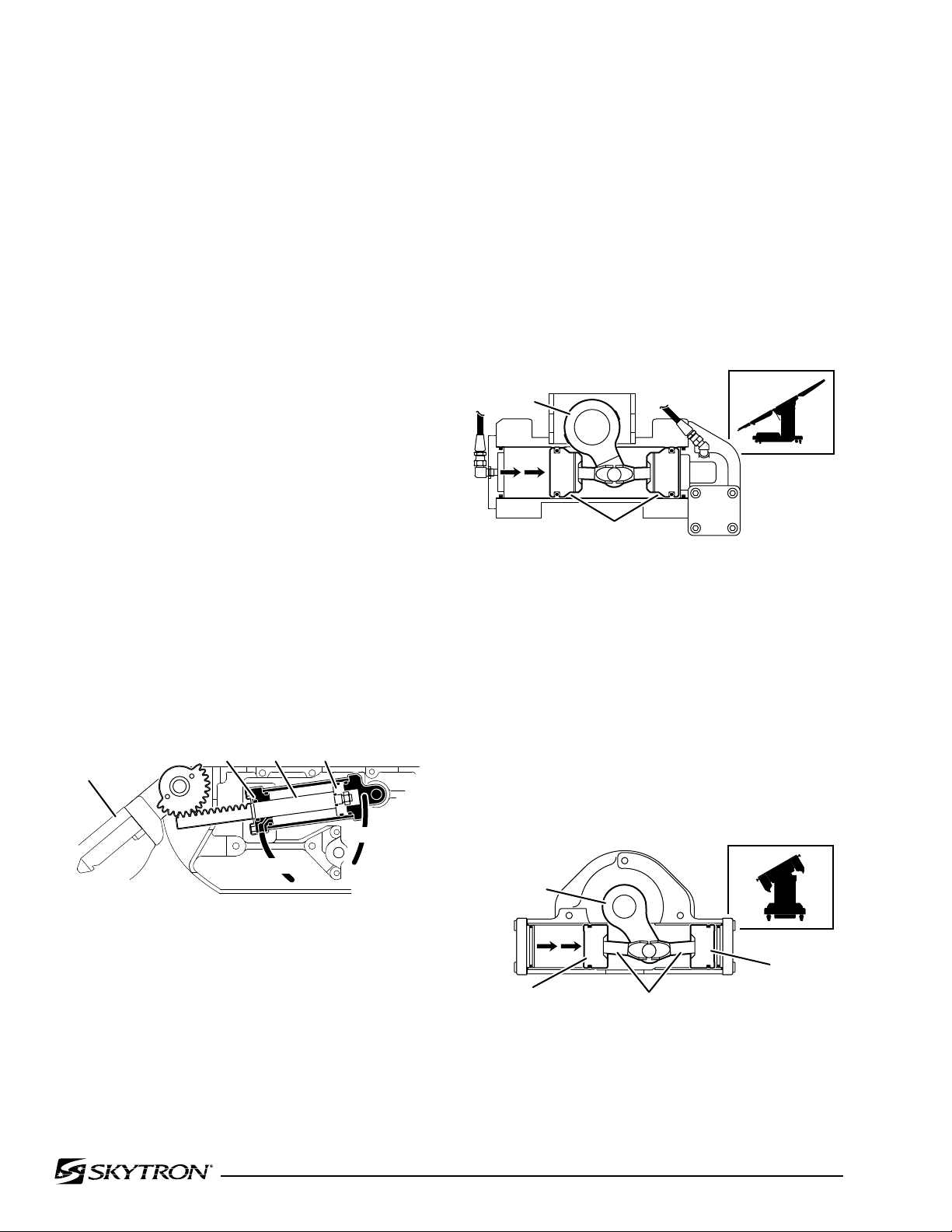
d. Hydraulic Cylinders (Slave Cylinders)
There are several different types of hydraulic cylinders used in the table that activate the control
functions. With the exception of the elevation and
brake cylinders, all operate basically the same way.
The control functions are listed below.
Back Section ------ 2 double action cylinders
Leg Section -------- 2 double action cylinders
Trendelenburg----- 1 double action cylinder
Lateral Tilt ---------- 1 double action cylinder
Elevation ----------- 1 single action cylinder
Kidney Lift ---------- 2 double action cylinders
Brakes -------------- 4 single action cylinders
1. Back Section and Leg Section Cylinders The double action cylinders are closed at one end
and have a movable piston with hydraulic fluid on
both sides. Connected to this piston is a ram or
shaft that exits out of the other end of the cylinder.
Through the use of either a gear, or clevis and pin
arrangement, this ram is connected to a movable
table surface. The movable surface can be moved
one way or the other by pumping hydraulic fluid
into the cylinder on either side of the piston. Obviously, if oil is pumped into one side of the cylinder,
a return path must be provided for the oil on the
other side. See figure 1-8.
2. Trendelenburg Cylinder Assembly - The Trendelenburg tilt assembly consists of two cylinders,
pistons and connecting rods. The connecting rods
connect to the Trendelenburg lever which connects
to the table side frames via the Trendelenburg axis.
When hydraulic fluid is pumped into one cylinder, the
piston and connecting rod pushes the Trendelenburg
lever which tilts the table top. To tilt the table top
in the opposite direction, fluid is pumped into the
opposite cylinder. See figure 1-9.
Figure 1-9. Trendelenburg Cylinder Assy.
3. Lateral Tilt Assembly - The lateral tilt assembly
consists of two cylinders, pistons and connecting
rods. The connecting rods attach to the lateral
tilt lever which connects to the table side frames.
When hydraulic fluid is pumped into one cylinder,
the piston and connecting rod pushes the lateral tilt
lever which tilts the table top to one side. To tilt the
table top in the opposite direction, fluid is pumped
into the opposite cylinder. See figure 1-10.
Figure 1-8. Back Section Cylinder
Figure 1-10. Lateral Tilt Cylinder Assembly
Page 13
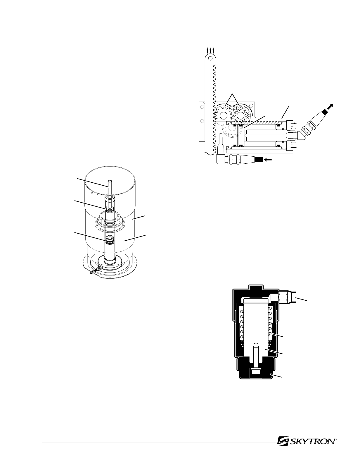
4. Elevation Cylinder - This single action cylinder
041905.025
PRIMARY
PISTON
SECONDARY
PISTON
ELEVATION
CYLINDER
SLIDER
ASSEMBLY
EXTERIOR
SHROUD
ASSEMBLY
041905.026
PINION
GEARS
OIL FLOW
CYLINDER
HOUSING
PISTON
KIDNEY LIFT
BAR
OIL
FLOW
041905.027
OIL LINE
RETURN SPRING
BRAKE PAD
PISTON
does not have hydraulic fluid on both sides of the
piston. It depends on the weight of the table top assembly to lower it. The cylinder is set in the center of
the elevation main column. The two stage cylinder
is elevated by the driven force of the oil pressure.
When lowering, the oil that is accumulated in the
cylinder is returned to the oil reservoir through
the mini-valve due to the table top weight. A slider
support assembly is used to support the weight of
the upper table section. A stainless steel shroud
covers the flexible hydraulic hoses and slider. See
figure 1-11.
Page 11
Figure 1-12. Kidney Lift Cylinder Assembly
Figure 1-11. Elevation Cylinder Assembly
5. Kidney Lift - The two kidney lift cylinder assemblies are a unique type of double action cylinder
where the piston remains stationary and the outer
housing or cylinder has the relative motion. The
cylinder housing has rack teeth cut into the top which
meshes with a pinion gear. This gear meshes with
other gears to supply the up or down drive for the
kidney lift bars, depending on which direction the
oil is pumped into the cylinder. See figure 1-12.
6. Brake Cylinders - The brake cylinders are
single action type similar to the elevation cylinder.
The movable piston's ram is connected to a brake
pad. See figure 1-13. Oil pumped into the top of the
cylinder pushes the piston down raising the table
base off its casters. An internal return spring on the
bottom of the piston, pushes the piston up to return
the oil through the mini-valve to the reservoir.
Figure 1-13. Single Action Brake Cylinder
Page 14
Page 12
041905.029
TO RESERVOIR THROUGH
PRESSURE RELIEF VALVE
INLET
RETURN TO
RESERVOIR
041905.028
MOTOR/PUMP
ASSEMBLY
PLUMBING
TERMINAL
BRAKE
BRAKE
BRAKE
BRAKE
EMERGENCY
BRAKE RELEASE
PRESSURE
RELIEF
VALVE
BRAKE
MINI-VALVE
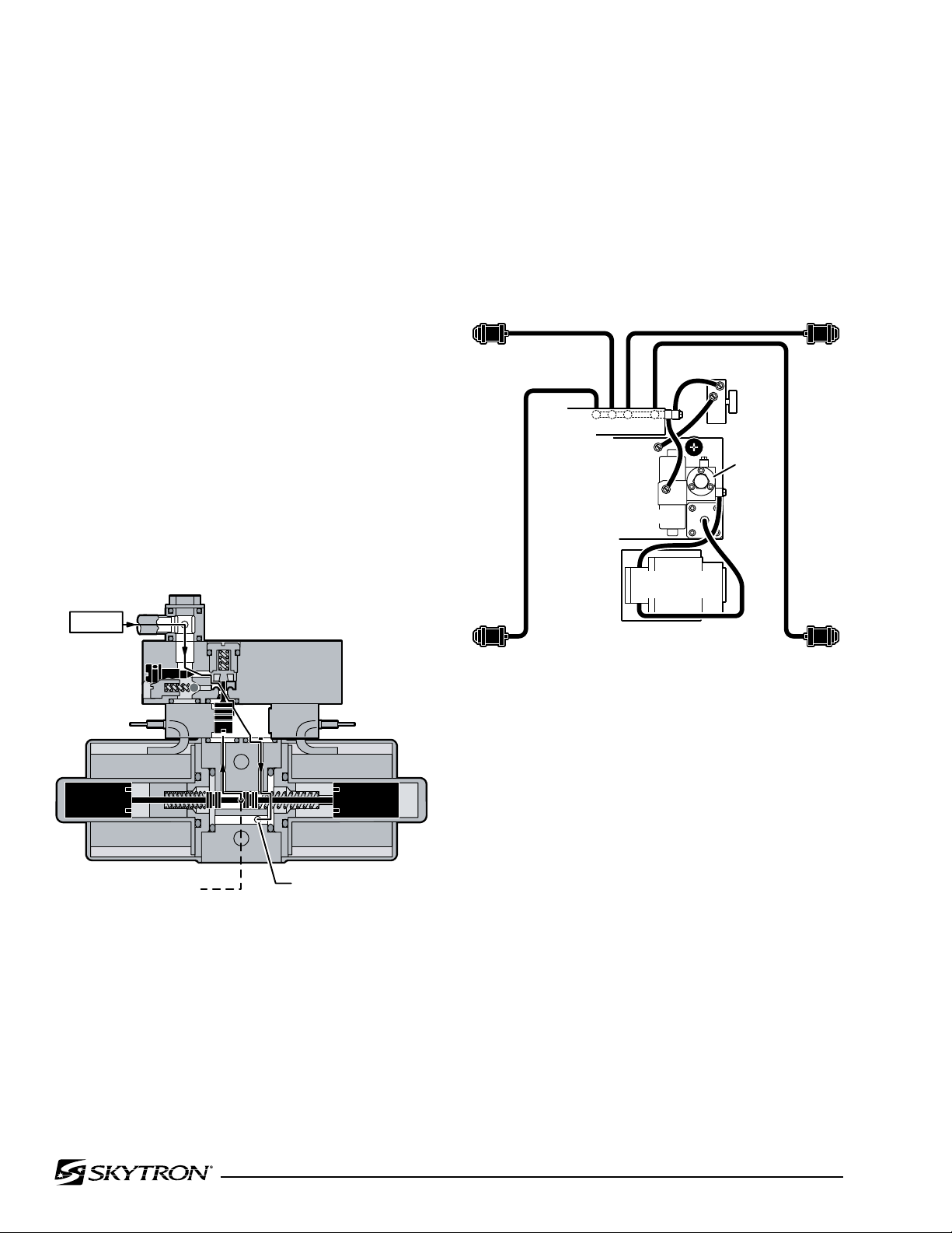
e. Elevation Cylinder Return Circuit
A three-way (single check valve type) mini-valve
controls both the elevation and return circuits. The
elevation circuit operation within the mini-valve is
identical to the operation of the four-way valves
previously described (inlet pressure opens the
check valve allowing the oil to enter the cylinder). In
the return position, inlet pressure pushes the pilot
plunger up and opens the return check valve. See
figure 1-14. The open check valve allows a path
for the oil in the elevation cylinder to return to the
reservoir. When the pilot plunger valve is opened,
the continuing pump pressure opens the pressure relief valve which provides a return oil path
to the reservoir.
The mini-valve used in the elevation circuit contains
only one check valve (all four-way mini-valves use
two check valves). The check valve is used to trap
the oil in the elevation cylinder thereby supporting
the table top. When the top is being lowered the
check valve is mechanically held open by the pilot
plunger through pump pressure.
2. 3-way (single check valve type) mini-valve.
3. Manually controlled emergency brake release.
4. Plumbing terminal, flexible hoses, copper
lines and "O" rings.
5. Portions of the electrical system.
Figure 1-14. Elevation Return Circuit
f. Brake System
The brake system consists of the following components: (figure 1-15)
1. Single action slave cylinders (4 each).
Figure 1-15. Brake System Block Diagram
Each corner of the cast-iron table base has a hydraulic brake cylinder. These single action cylinders are
hydraulically connected in parallel to the mini-valve
and all four are activated together. It is normal for
one corner of the table to raise before the others
due to the weight distribution of the table.
An electronic timer in the relay box is activated when
any function on the pendant control is pushed
momentarily. The pump/motor and brake system
mini-valve are activated and the brake cylinders
are completely set. The electronic timer runs for
approx. 8-10 seconds.
The brakes are released by pushing the BRAKE
UNLOCK button momentarily. An electronic timer in
the relay box activates the brake function hydraulic
mini-valve and pump/motor.
Page 15
041905.030
EMERGENCY
BRAKE RELEASE
FLEX/
REFLEX
2
7
3 7
PLUMBING
TERMINAL
2
TREND.
7
BACK
UP
MINI-
VALVES
6
BACK
DOWN
2 6
3
REV.
TREND.
041905.031
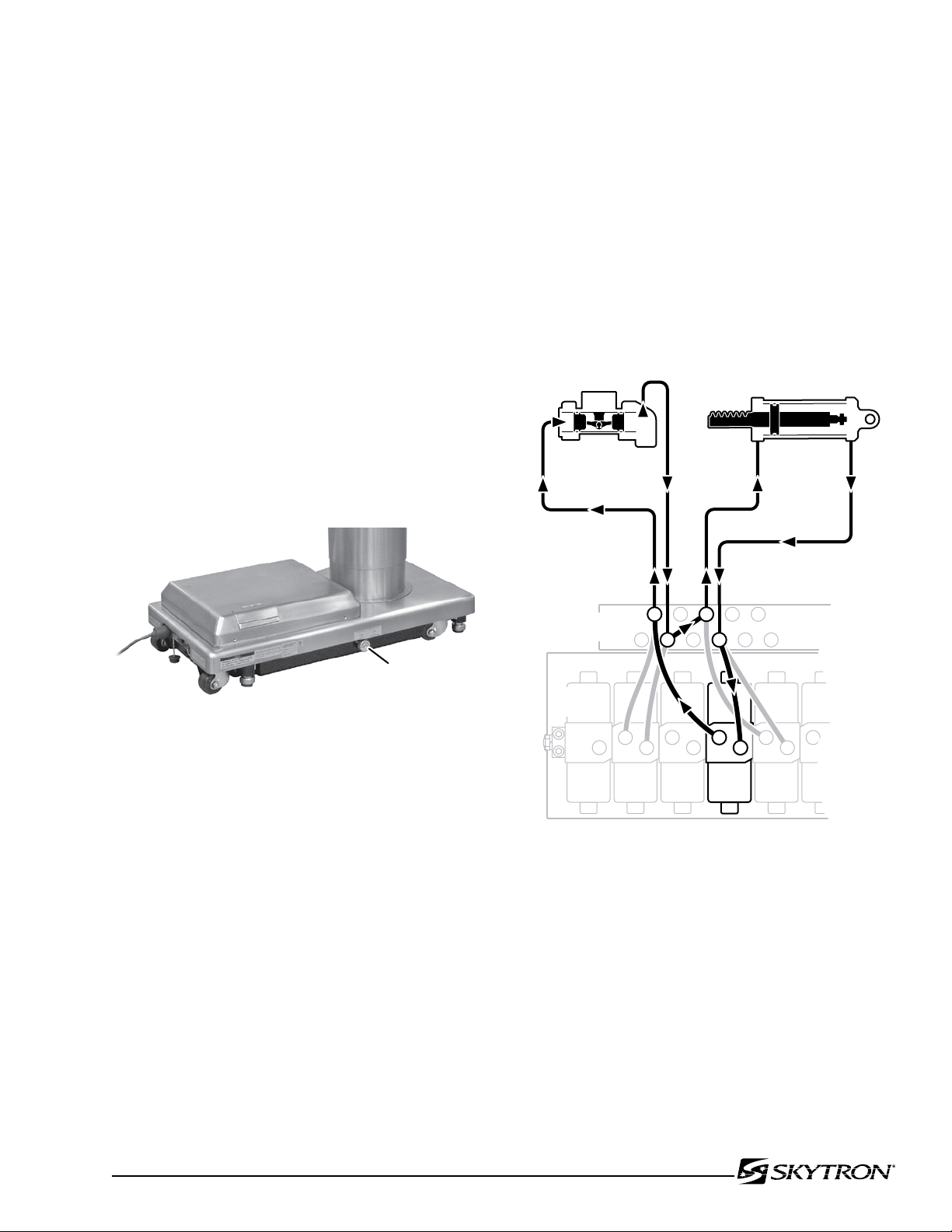
h. Flex/Reflex System
Page 13
When activated, the return hydraulic circuit operates
similar to the elevation cylinder return circuit. Return springs inside the single action brake cylinders
retract the brake pads and provide the pressure to
return the hydraulic oil back to the reservoir. The
electronic timer operates the return circuit for approximately 8-10 seconds.
g. Emergency Brake Release
The emergency brake release is simply a manually
operated bypass valve connected in parallel to the
brake cylinders and the oil reservoir. See figure
1-16. When the valve is opened (turned counterclockwise) a return circuit for the brake hydraulic
fluid is opened. The return springs force the pistons
up pushing the hydraulic oil back into the reservoir
and retracting the brake pads.
The Flex/Reflex system incorporates an additional
mini-valve which connects the trendelenburg and
back section hydraulic systems in a series. When
FLEX is activated by the pendant control, the Flex/
Reflex mini-valve opens the oil pressure path to the
Reverse Trendelenburg piston. The return oil path
from the Trendelenburg piston is routed through the
back section cylinder to the mini-valve return port.
See figure 1-17
Figure 1-16.
NOTE
•The emergency brake release valve
must be tightened securely when not
in use.
•If the emergency brake release valve
has been operated, the UNLOCK button
on the pendant control may have to be
pressed before brakes will lock again.
If the emergency brake release valve is open, the
brakes will release slowly- depending on how loose
the valve is, this could take anywhere from a few
minutes to several hours.
Figure 1-17. Flex/Reflex System
Page 16

Page 14
041905.032
FILLER CAP
FITTING
GASKET
OIL TANK
RESERVOIR
041905.033
PRESSURE
RELIEF
VALVE
PRESSURE
GAUGE
PLUMBING
BOLT
1-3. Hydraulic Adjustments
a. Fluid Level.
The fluid level should be approximately 1/2" below
the filler hole or gasket surface. If additional fluid
is needed, remove the filler vent cap with a phillips
screwdriver and add fluid through this opening
using a funnel. See figure 1-18.
NOTE
The elevation cylinder should be completely down, the brakes released and all
the other control functions in their neutral
position when checking oil level.
NOTE
Whenever a hydraulic line or component
is replaced, bleed the air out of the line
using the pump pressure by activating
the function before making the final connection. Then operate the function until
it stalls in both directions.
c. Pressure Relief Valve
The pressure relief valve is adjusted by turning
the adjustment nut until the desired pressure is
reached.
To adjust:
1. Remove the blind cap and attach a hydraulic
pressure gauge to the main oil galley using a 6mm
plumbing bolt. See figure 1-19.
The type of oil that should be used is SKYTRON P.N.
D6-010-90 or equivalent. This is a very high quality
hydraulic oil. The table requires approximately two
quarts of oil to operate properly. Excercise caution
when determining equivalance to avoid damage to
the hydraulic system.
b. Bleeding The Hydraulic System
To purge the air from the hydraulic system, operate each function back and forth at least two or
three times.
Figure 1-18.
Figure 1-19.
2. Raise the table top until the piston reaches
the end of its stroke and stalls. Observe reading
on pressure gauge and turn the adjustment nut
(clockwise to increase oil pressure, counterclockwise to decrease) until desired reading is obtained.
Pressure should be 8MPA (80KG/CM2 -1138 PSI).
An erratic reading and/or inability to adjust to the
recommended setting may indicate the need for
replacement of the pressure relief valve.
Page 17
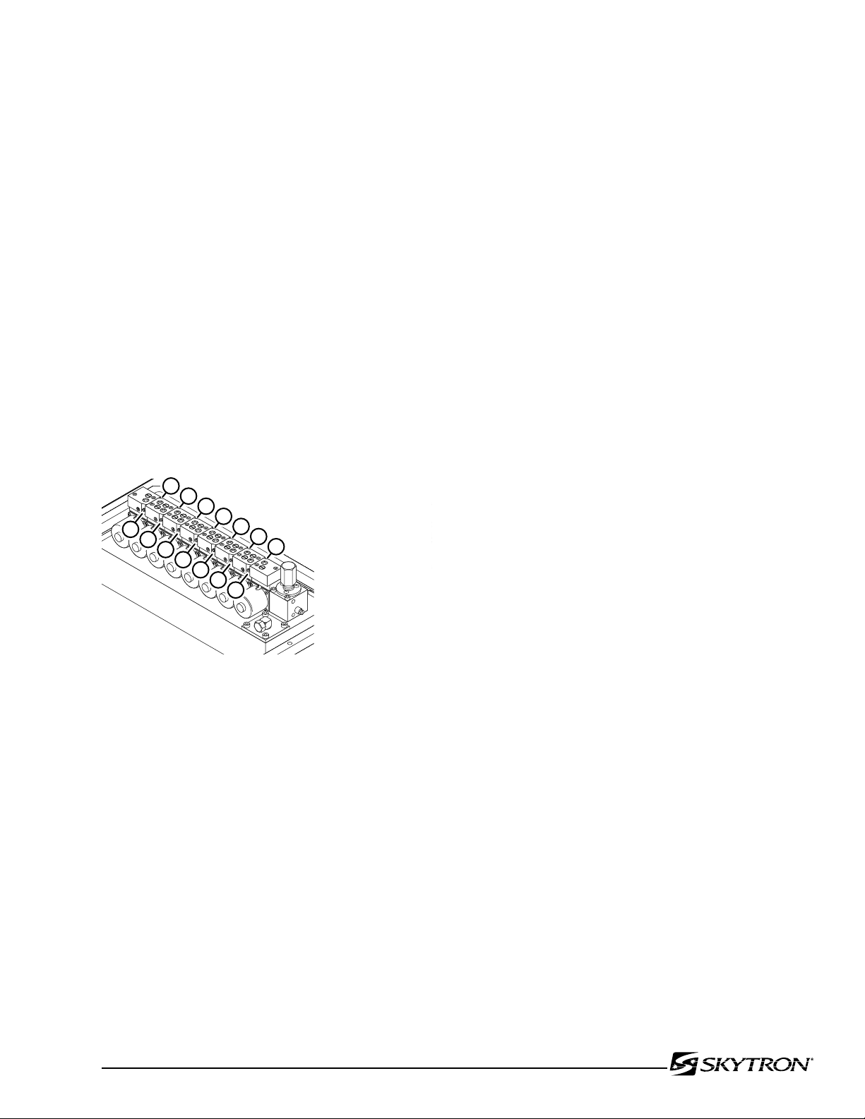
d. Speed Controls
1
2
3
4
5
6
7
8
9
10
11
12
13
14
1.
2.
3.
4.
5.
6.
7.
8.
9.
10.
11.
12.
13.
14.
TABLE DOWN
REVERSE TREND.
TRENDELENBURG
TILT RIGHT
TILT LEFT
REFLEX
FLEX
BACK UP
BACK DOWN
FOOT DOWN
FOOT UP
KIDNEY UP
KIDNEY DOWN
BRAKES
041905.034
Page 15
The speed controls restrict the volume of oil returning
back to the reservoir thereby controlling the speed
of each control function.
All four-way mini-valves, have two speed controls
located in the ends of each valve body. All three-way
mini-valves have only one speed control.
One speed control adjusts one direction of a
particular function and the opposite speed control
adjusts the other direction. They are adjustable by
using a small straight blade screwdriver and turning the adjustment screw clockwise to decrease
the speed and counterclockwise to increase the
speed. See figure 1-20.
Any control function should move in either direc-tion
at the same rate. If the rate of a certain function
is too slow, open the speed control slightly and recheck. Use the second hand on a watch and time a
particular function. Match that time in the opposite
direction by opening or closing the speed control.
Approximate operating times are as follows:
Lateral Tilt 7 seconds
Back Up 25 seconds
Back Down 15 seconds
Kidney Lift 7 seconds
A pressure gauge should be used to set the speed
of the back section, Trendelenburg and flex control
functions.
To adjust:
1. Attach the pressure gauge onto the main
oil galley as shown in figure 1-19.
2. The gauge should read the following values when operating the various control functions
in either direction. Turn the speed controls until
desired values are obtained.
Back Section Up 65KG/CM2 -925PSI
Figure 1-20.
Dn 65KG/CM
Trendelenburg Up 65KG/CM2 -925PSI
Dn 65KG/CM
Flex 70KG/CM
Reflex 70KG/CM
2
-925PSI
2
-925PSI
2
-925PSI
2
-925PSI
NOTE
When adjusting Flex/Reflex speed controls, set Reflex last.
Elevation - There is not a speed adjustment for
raising the table. The speed control will only affect
the rate of descent and it should equal the rate of
elevation.
Page 18
Page 16
041905.035
ALLEN WRENCH
ECCENTRIC
CAM
SET
SCREW
041905.036
BACK SECTION
SET
SCREW
BACK SECTION
CYLINDER
ECCENTRIC CAM
SEAT SECTION
TOP
SECTION II MECHANICAL TABLE ADJUSTMENTS
2-1. Back Section Gear Mesh Adjustment
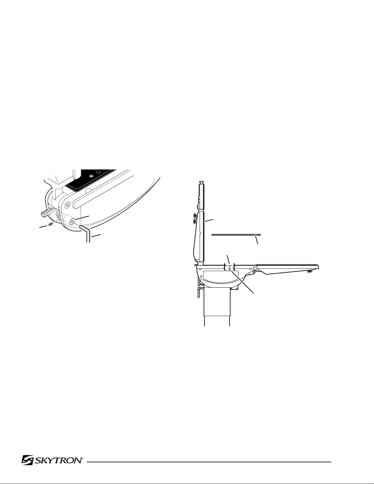
The gear mesh is adjusted by the use of an eccentric cam. This cam moves the gear teeth closer
together to eliminate gear lash. This adjustment
arrangement compensates for any wear between
the gears that might occur.
To adjust:
Loosen the cam locking allen set screw. Use an
allen wrench to rotate the eccentric cam. See figure
2-1. Tighten the locking set screw when adjustment
is complete.
Any twisting or flexing of the back section as it approaches the stalled position indicates that one of
the cylinders is not reaching its fully extended position at the same time as the other. This condition
would require an adjustment.
To adjust:
Remove the seat section top for access to the
cam locking set screws and loosen the set screws.
Use an allen wrench to turn the cylinder eccentric
cams as required to shift either cylinder fore or
aft as needed so no twisting or flexing of the back
section is observed when it is stalled in the full up
position. See figure 2-2. Tighten the set screws and
replace the seat section top when the adjustment
is completed.
Figure 2-1. Eccentric Cam Adjustment
2-2. Hydraulic Cylinder Adjustment
The hydraulic cylinder rams that control both the
back and foot / leg sections must move together so
that these sections are not twisted when operated.
This is accomplished by the use of eccentric cams
that move the cylinder bodies fore and aft to adjust
their effective stroke.
NOTE
Adjust gear mesh before adjusting eccentric cams for the back section.
a. Back Section
Position the back section all the way up until it
stalls. Both sides of the back section should stop
moving at the same time and should not show any
signs of twisting.
Figure 2-2. Back Section Adjustment
b. Leg Section
Position the leg section all the way up. Both sides
of the leg section should stop moving at the same
time and should not show any signs of twisting.
Any twisting or flexing of the leg section as it approaches the stalled position indicates that one of the
cylinders is not reaching its fully extended position
at the same time as the other and an adjustment
is required.
Page 19
NOTE
041905.037
6700B
NAMEPLATE
LEG SECTION
LEG SECTION CYLINDER
ECCENTRIC CAM
(behind nameplate)
041905.038
ALLEN
BOLT
ALLEN
BOLTS
ADJUSTMENT
SET SCREW
Page 17
2-3. Head Section Adjustment
The head section can be adjusted to eliminate any
flexing throughout it's range of travel.
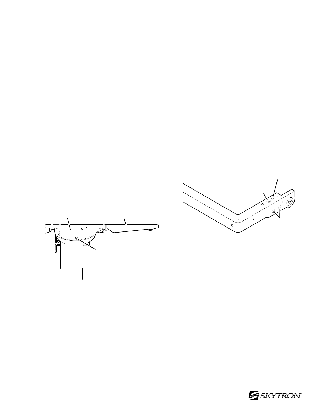
The leg section cylinder eccentric cam
is located under the nameplate on the
side casting. To make an adjustment, the
nameplate will have to be removed and
a new nameplate will have to be installed
when the adjustment is completed.
To adjust:
Loosen the cam locking set screws located inside
the table side frames. See figure 2-3. Use an allen wrench to turn the cylinder eccentric cams
as required to shift either cylinder fore or aft as
needed so no twisting or flexing of the leg section is
observed when it is stalled in the above horizontal
position. Tighten set screws when proper adjustment is achieved.
To adjust:
Place the head section in level position and remove
the top. See figure 2-4. Loosen but do not remove
the allen bolts securing the bearing block to the
frame. Loosen the allen bolt in the top of the frame
and turn the set screw as required to achieve proper
adjustment. One or both of the blocks may require
adjustment to achieve proper alignment. Tighten
all allen bolts when adjustment is complete. Test
the head section throughout its range of travel.
Re-adjust as needed. Replace top section when
proper adjustment is achieved.
Figure 2-3. Leg Section Adjustment
Figure 2-4. Head Section Adjustment
2-4. Trendelenburg Cap Bolt Torque Procedure
Over time the Trendelenburg tail cap bolts will
loosen, resulting in the Trendelenburg tail cap sliding out of the cylinder housing.
To adjust:
Using a 6mm allen wrench, remove the cover from
the head and foot end of the Trendelenburg cylinder
housing. Using a 14mm wrench, slightly loosen the
hydraulic line connection on the head end to relieve
pressure in the Trendelenburg cylinder.
NOTE
Ensure to place a shop rag around the
connection to collect hydraulic oil that
will escape!
Page 20
Page 18
GRAVITY
STOP
SIDE
RAIL
82106-102
2-6 Casters
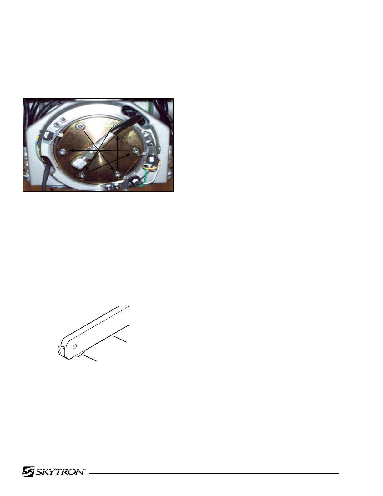
Using a 5mm allen wrench, torque each bolt to 18
N/meter (13.27 ft/lbs) on the head and foot end of
the Trendelenburg cylinder following the star pattern
shown in Fig. 2.5. Tighten the hydraulic line connection and replace both end covers when finished.
1
6
4
Fig 2-5. Cap Bolt Torque Sequence
3
5
2
Clean and lubricate each of the casters. Remove
any debris caught in the casters and old grease.
Lubricate using a grease gun and conventional
wheel bearing grease. The casters should rotate
freely providing a smooth movement of the table
during positioning. Replace worn or defective casters as required.
2-5. Side Rails
Inspect each of the side rail sections. Make sure
that all retaining hardware is tight. Inspect the gravity stops. Make sure that each gravity stop moves
freely. Clean, lubricate or replace as necessary.
See figure 2-6.
Figure 2-6
Page 21
3-1. Precautions
Page 19
SECTION III HYDRAULIC TROUBLESHOOTING
Before attempting to troubleshoot any hydraulic
problem on the table, please read through the precautions and notes below.
CAUTION
When disconnecting any of the hydraulic
lines, fittings, joints, hoses, etc., for the
following control functions, be sure these
table surfaces are in their down position
or completely supported.
Elevation
Back Section
Leg Section
Kidney Lift
When working on the trendelenburg
or lateral tilt hydraulic circuits, be sure to
support the table top. When working on
the brake system make sure the brakes
are completely retracted.
5. Is the problem no movement of a table surface
or does the table surface lose position?
Once the problem has been determined, concentrate on that particular hydraulic circuit or control
function.
Listed below are the hydraulic components that
are common with all hydraulic circuits. If there is a
problem with any of them, it could affect all control
functions.
1. Motor/Pump Assembly
2. Reservoir
3. Pressure Relief Valve
4. Certain Oil Lines and Galleys
If there was a problem in the following components,
only one control function would normally be affected.
1. Mini-Valve
2. Slave Cylinder
3. Oil Lines
WARNING
Failure to follow these precautions may
result in an uncontrolled oil spray and
damage to the table or personal injury.
3-2. Troubleshooting Notes
When troubleshooting a table malfunction, first
determine the following:
1. Does the problem affect all control functions?
2. Does the problem affect only one control
function?
3. If the problem affects one control function is
it in both directions?
4. Is the problem intermittent?
NOTE
Whenever a hydraulic line or component
is replaced, bleed the air out of the lines
using the pump pressure before making
the final connection. After all connections are tight, cycle the control function
back and forth two or three times to purge
the remaining air from the system.
CAUTION
When installing new "O" rings use
hydraulic oil or white lithium grease to
thoroughly lubricate the "O" rings and
cylinder. Keep everything clean.
Each complete oil circuit is shown on the following
pages. When troubleshooting a particular function,
refer to the appropriate oil circuit diagram and the
list of possible problems.
Page 22
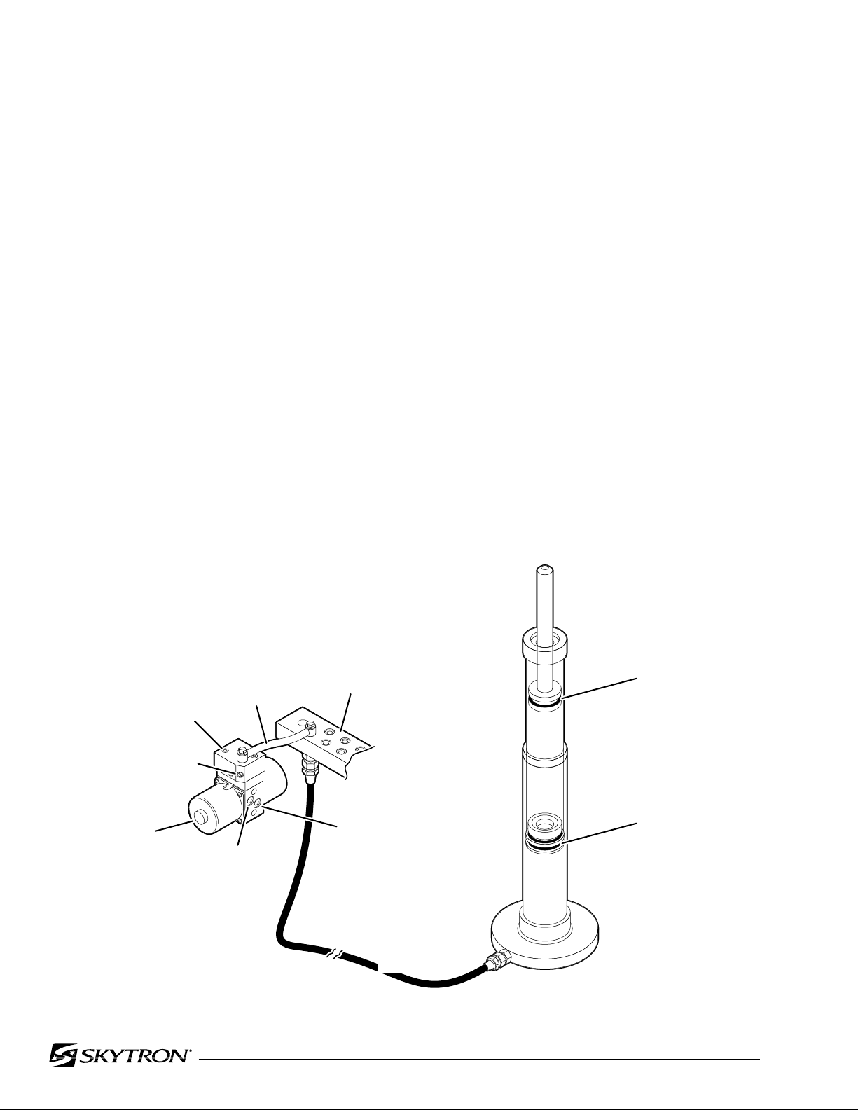
Page 20
041905.039
PRIMARY PISTON
O-RING
SECONDARY PISTON
O-RING
PLUMBING
TERMINAL
MINI-VALVE
FLEXIBLE
HOSE
COPPER
LINE
INTERNAL
OIL RETURN
TO RESERVOIR
INTERNAL OIL
FROM PUMP
CHECK
VALVE
SPEED CONTROL
3-3. ELEVATION DIAGNOSIS CHART
Problem
Table will not elevate properly
Table will not descend properly
Table loses elevation
Reason
Pressure Relief Valve Not Set Properly
Low on Oil
Spool Valve Not Centered
Defective Pump
Defective Mini-Valve
Defective Solenoid or Wiring
Defective Relay Box or Pendant Control
Leaking Cylinder Hose
Uneven Weight Distribution
Incorrect Speed Adjustment
Bad Check Valve
Spool Valve Not Centered
Galled Slider Assembly
Defective Solenoid or Wiring
Defective Relay Box or Pendant Control
Uneven Weight Distribution
Bad Check Valve
Leaking Mini-Valve
Loose Fittings, Joints, Hoses
Leaking "O" Ring Inside Cylinder
Figure 3-1. Elevation Circuit
Page 23
3-4. TRENDELENBURG DIAGNOSIS CHART
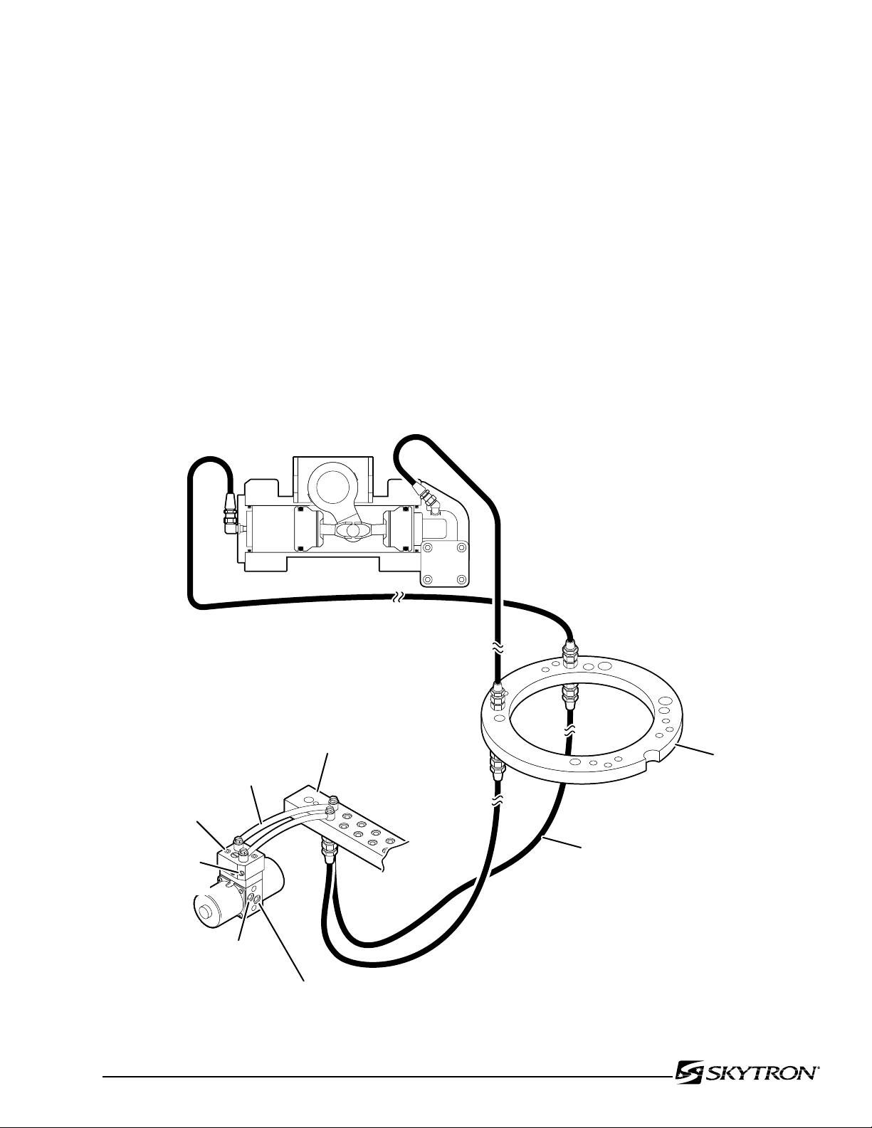
041905.042
SPEED
CONTROL
CHECK
VALVE
TRENDELENBURG CIRCUIT
CLAMP RING
FLEXIBLE
HOSE
MINI-VALVE
INTERNAL OIL RETURN TO RESERVOIR
INTERNAL
OIL FROM PUMP
COPPER
LINE
PLUMBING
TERMINAL
Page 21
Problem
Trendelenburg function moves improperly
Trendelenburg function chatters or loses position
Reason
Incorrect Speed Adjustment
Spool Valve Not Centered
Bad Check Valves
Low on Oil
Pinched Hose
Defective Mini-Valve
Pressure Relief Valve Not Set Properly
Bad Solenoid or Wiring
Defective Relay Box or Pendant Control
Defective or Dirty Check Valve
Oil Leakage in Circuit
Air Inside Cylinder
Pinched Hose
Low on Oil
Figure 3-2. Trendelenburg Circuit
Page 24
Page 22
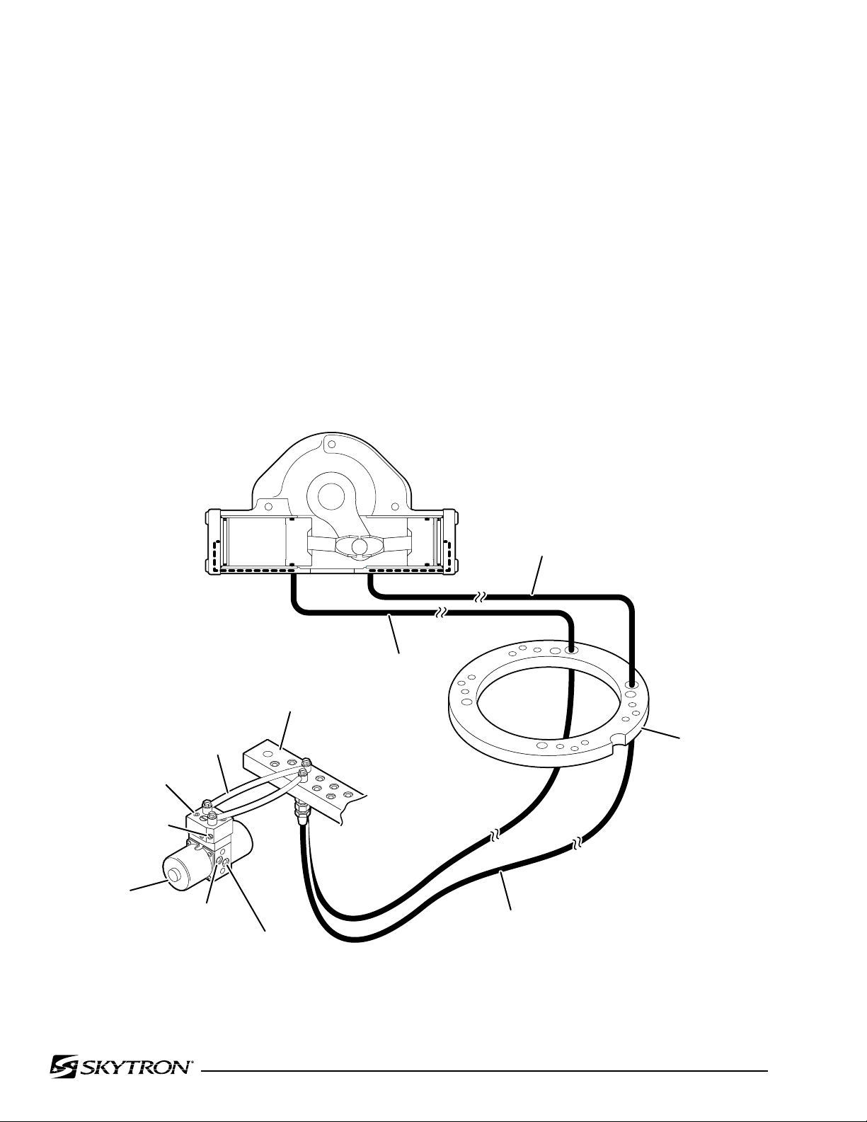
041905.041
LATERAL TILT
CYLINDER
CLAMP RING
PLUMBING
TERMINAL
MINI-VALVE
COPPER
LINE
INTERNAL
OIL RETURN
TO RESERVOIR
INTERNAL OIL
FROM PUMP
FLEXIBLE
HOSE
LEFT CIRCUIT
RIGHT CIRCUIT
CHECK
VALVE
SPEED CONTROL
3-5. LATERAL TILT DIAGNOSIS CHART
Problem
Lateral tilt function moves improperly
Lateral tilt function chatters or loses position
Reason
Incorrect Speed Adjustment
Spool Valve Not Centered
Bad Check Valves
Low on Oil
Pinched Hose
Defective Mini-Valve
Pressure Relief Valve Not Set Properly
Bad Solenoid
Defective Relay Box or Pendant Control
Defective or Dirty Check Valves
Oil Leakage in Circuit
Air Inside Cylinder
Pinched Hose
Low on Oil
Figure 3-3. Lateral Tilt Circuit
Page 25
3-6. FLEX SYSTEM DIAGNOSIS CHART
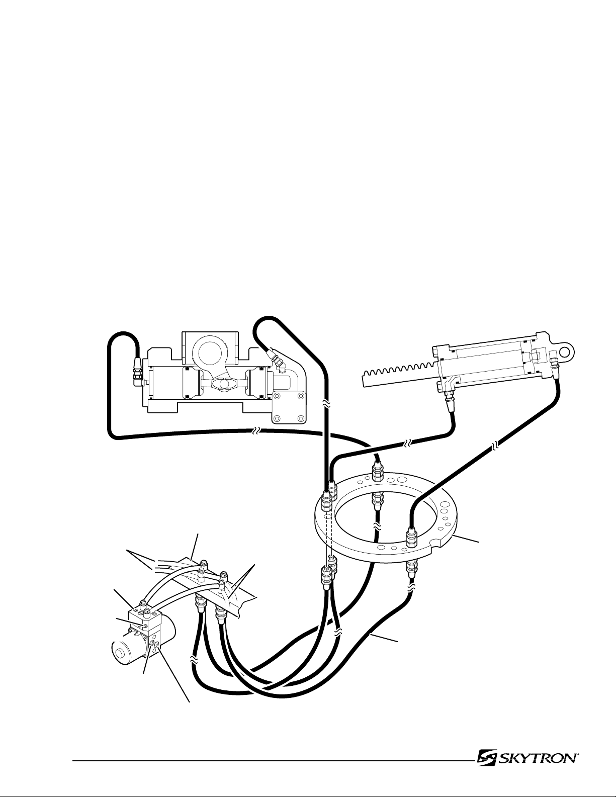
041905.040
TO TRENDELENBURG
MINI-VALVE
TO BACK SECTION
MINI-VALVE
SPEED
CONTROL
CHECK
VALVE
PLUMBING
TERMINAL
TRENDELENBURG CIRCUIT
BACK SECTION CIRCUIT
CLAMP RING
MINI-VALVE
INTERNAL OIL RETURN TO RESERVOIR
INTERNAL
OIL FROM PUMP
FLEXIBLE
HOSE
Page 23
Problem
Back Section or Trendelenburg function moves
improperly
NOTE
If Flex System does not function
properly, check the back section and
Trendelenburg functions before adjusting the flex system.
Back Section or Trendelenburg function chatters
or loses position
Reason
Incorrect Speed Adjustment (Trendelenburg,
Back
section or Flex - check with gauge)
Spool Valve Not Centered
Bad Check Valves
Low on Oil
Pinched Hose
Defective Mini-Valve
Pressure Relief Valve Not Set Properly
Bad Solenoid
Defective Relay Box or Pendant Control
Kidney Bridge Raised
Defective or Dirty Check Valves
Oil Leakage in Circuit
Air Inside Cylinder
Pinched Hose
Low on Oil
Figure 3-4. Flex System Circuit
Page 26
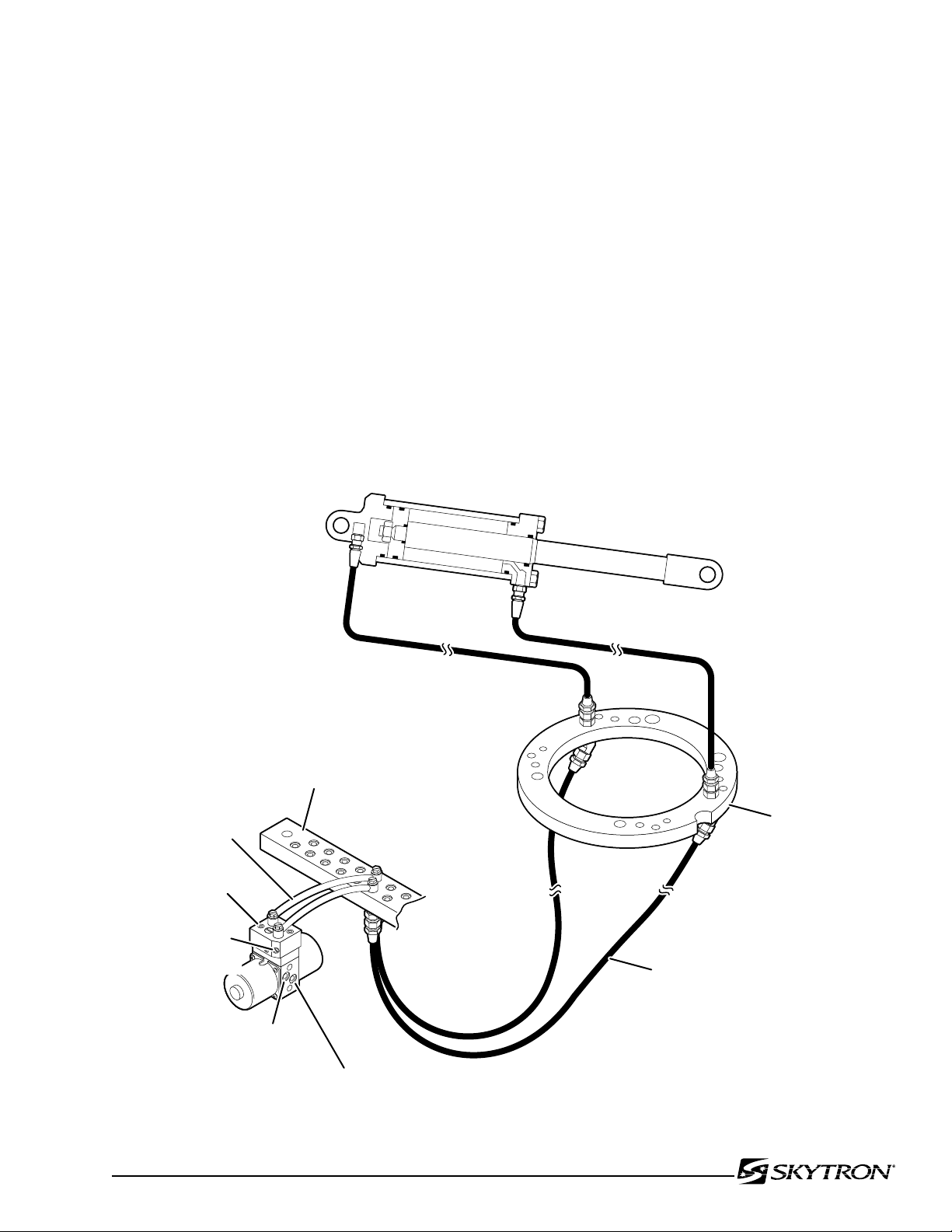
Page 24
041905.043
BACK SECTION
CYLINDER
DOWN CIRCUIT
UP CIRCUIT
CLAMP RING
FLEXIBLE
HOSE
SPEED
CONTROL
CHECK
VALVE
COPPER
LINE
MINI-VALVE
INTERNAL OIL RETURN TO RESERVOIR
INTERNAL
OIL FROM PUMP
PLUMBING
TERMINAL
3-7. BACK SECTION DIAGNOSIS CHART
Problem
Back Section function moves improperly
Back Section function chatters or loses position
Reason
Incorrect Speed Adjustment
Spool Valve Not Centered
Bad Check Valves
Low on Oil
Pinched Hose
Defective Mini-Valve
Pressure Relief Valve Not Set Properly
Bad Solenoid
Defective Relay Box or Pendant Control
Kidney Bridge Raised
Defective or Dirty Check Valves
Oil Leakage in Circuit
Air Inside Cylinder
Pinched Hose
Low on Oil
Figure 3-5. Back Section Circuit
Page 27
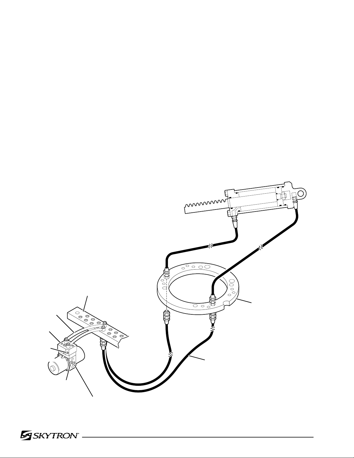
3-8. LEG SECTION DIAGNOSIS CHART
041905.044
LEG SECTION
CYLINDER
DOWN CIRCUIT
UP CIRCUIT
CLAMP RING
SPEED
CONTROL
CHECK
VALVE
COPPER
LINE
MINI-VALVE
INTERNAL OIL RETURN TO RESERVOIR
INTERNAL
OIL FROM PUMP
PLUMBING
TERMINAL
FLEXIBLE
HOSE
Page 25
Problem
Leg function moves improperly
Leg function chatters or loses position
Reason
Incorrect Speed Adjustment
Spool Valve Not Centered
Bad Check Valves
Low on Oil
Pinched Hose
Defective Mini-Valve
Pressure Relief Valve Not Set Properly
Bad Solenoid
Defective Relay Box or Pendant Control
Defective or Dirty Check Valves
Oil Leakage in Circuit
Air Inside Cylinder
Pinched Hose
Low on Oil
Figure 3-6. Leg Section Circuit
Page 28
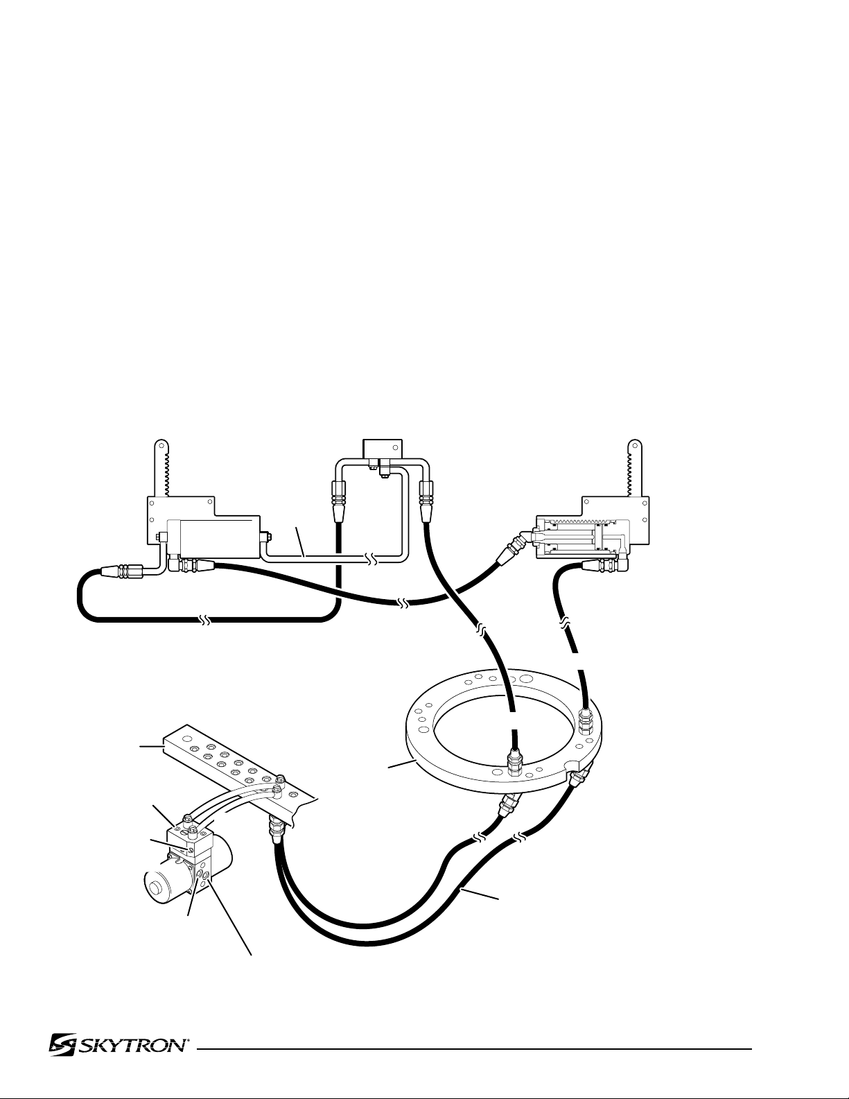
Page 26
041905.045
CLAMP
RING
SPEED
CONTROL
CHECK
VALVE
MINI-VALVE
INTERNAL OIL RETURN TO RESERVOIR
INTERNAL
OIL FROM PUMP
PLUMBING
TERMINAL
FLEXIBLE
HOSE
COPPER
LINE
COPPER
LINE
KIDNEY LIFT
CYLINDER
KIDNEY LIFT
CYLINDER
EQUALIZATION TERMINAL
DOWN CIRCUIT
UP CIRCUIT
3-9. KIDNEY LIFT DIAGNOSIS CHART
Problem
Kidney Lift moves improperly
Kidney Lift chatters or loses position
Reason
Incorrect Speed Adjustment
Spool Valve Not Centered
Bad Check Valve
Low on Oil
Pinched Hose
Defective Mini-Valve
Pressure Relief Valve Not Set Properly
Bad Solenoid
Defective Relay Box or Pendant Control
Defective or Dirty Check Valve
OiI Leakage in Circuit
Air Inside Cylinder
Pinched Hose
Low on Oil
Lift Rods Binding
Figure 3-7. Kidney Lift Circuit
Page 29
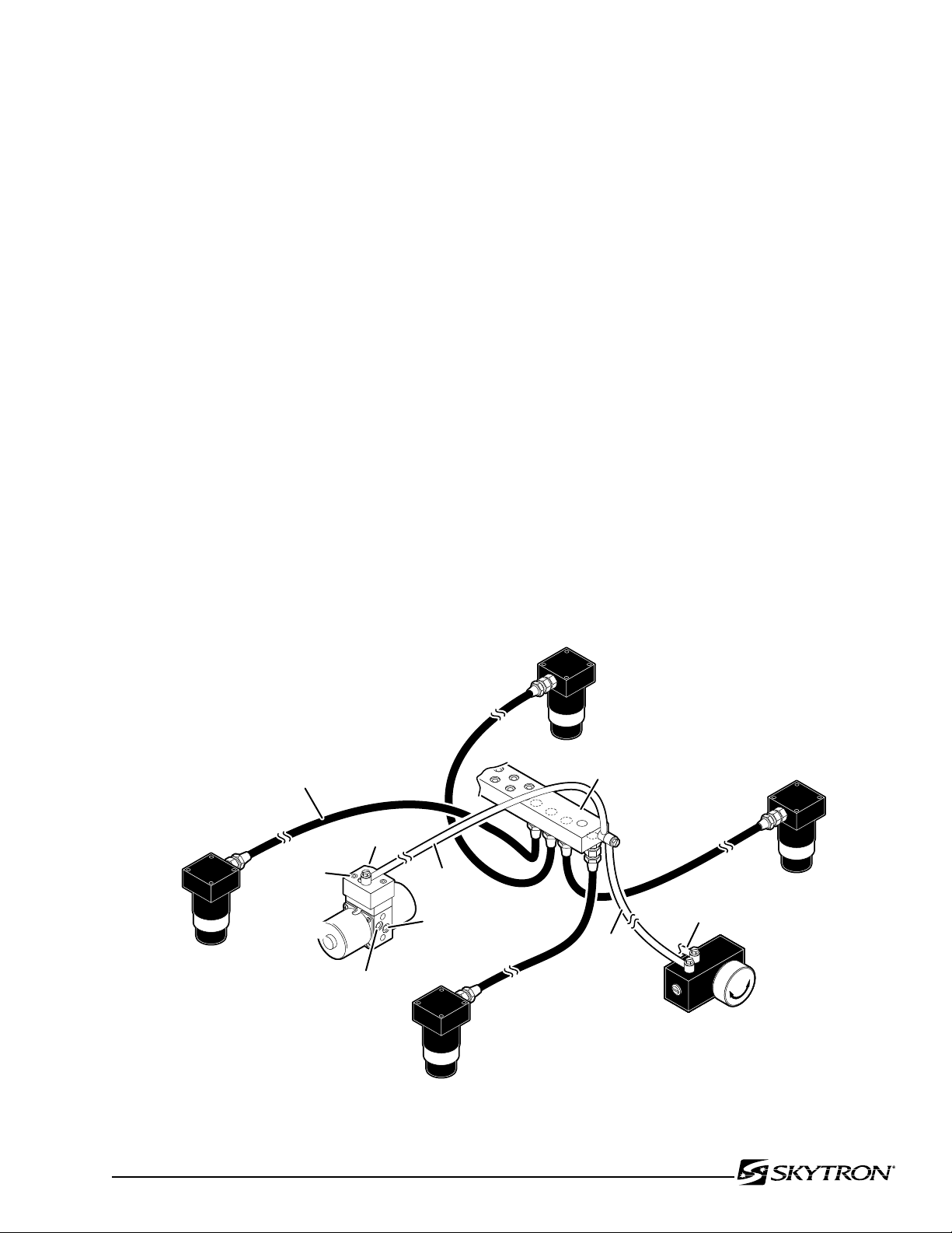
3-10. BRAKE CIRCUIT DIAGNOSIS CHART
041905.046
SPEED
CONTROL
CHECK
VALVE
PLUMBING
TERMINAL
INTERNAL
OIL RETURN
TO RESERVOIR
FLEXIBLE
HOSE
BRAKE
CYLINDER
BRAKE
CYLINDER
BRAKE
CYLINDER
EMERGENCY
BRAKE RELEASE
VALVE
BRAKE
CYLINDER
COPPER
LINE
COPPER
LINE
RETURN
TO RESERVOIR
MINI-
VALVE
INTERNAL
OIL FROM PUMP
Page 27
Problem
Brakes will not set properly
NOTE
If brakes have been released with
the Emergency Brake Release Valve,
brakes will not reset until BRAKE UNLOCK Circuit has been activated.
Brakes Will Not Stay Locked
Brakes will not retract properly
Reason
Emergency Brake Release Valve Open or Defective
Spool Valve Not Centered
Bad Check Valve
Low on Oil
Pressure Relief Valve Not Set Properly
Pinched Hose
Defective Mini-Valve
Defective Relay Box or Pendant Control
Emergency Brake Release Valve Open or Defective
Defective or Dirty Check Valve
Oil Leakage in Circuit
Leaking "O" Ring Inside Cylinder
Incorrect Speed Adjustment
Bad Check Valve
Spool Valve Not Centered
Defective Mini-Valve
Pinched Hose
Defective Solenoid or Wiring
Defective Relay Box or Pendant Control
Defective Brake Cylinder
Figure 3-8. Brake System Circuit
Page 30
Page 28
ELEV BRAKEKIDNEYLEGBACKFLEXTILTTREND
1 3
2
2
5
4 2
7 7 9
6 8
4 8
10
11
12
10
1
1
2
2
3
4 5
6
7
8 9
9
8
7
6
09
0908
06
07
08
07
06
3
3 5
6
10
10
11
10
11
7 9
11
101110
10
ELEVATION
CYLIDER
TRENDELENBURG
KIDNEY LIFT
KIDNEY LIFT
MOTOR/PUMP
ASSEMBLY
LEG SECTION
BACK SECTION
LEG SECTION
PLUMBING
TERMINAL
BYPASS
VALVE
PRESSURE
RELIEF VALVE
(4) BRAKE ASSEMBLY
EMERGENCY
BRAKE RELEASE
MINI-
VALVES
TILT TILT
11
105
380
520
520
280
300
225
540
700
440
350
350
440
380
220
1040
1070
1000
1220
1070
1100
1040
1050
600
550
550
600
240
630
80
40
80
40
80
80
80
80
1160
1130
150
140
125
380
240
135
120
130
100
115
120
140
135 100
100
31.6
041905.047mj
BACK SECTION
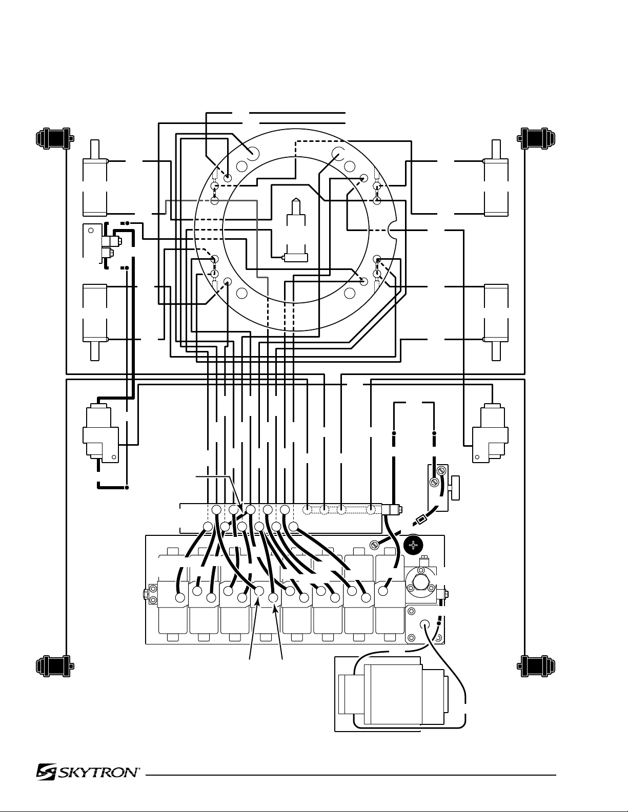
3-11. Flexible Hose Identification and Placement
The flexible hydraulic hoses used in the table are
number coded to aid in the correct placement of
the hoses from the plumbing terminal to their respective hydraulic cylinders. Figure 3-9 shows the
correct placement of the flexible hydraulic hoses
and their respective number codes.
Figure 3-9. Flexible Hoses
Page 31
3-12. Kidney Lift System
041905.048
LEFT CYLINDER
RIGHT CYLINDER
D C
B A
BYPASS VALVE (closed)
KIDNEY LIFT
DOWN
041905.049
LEFT CYLINDER
RIGHT CYLINDER
D C
B A
BYPASS VALVE (open)
KIDNEY LIFT
UP
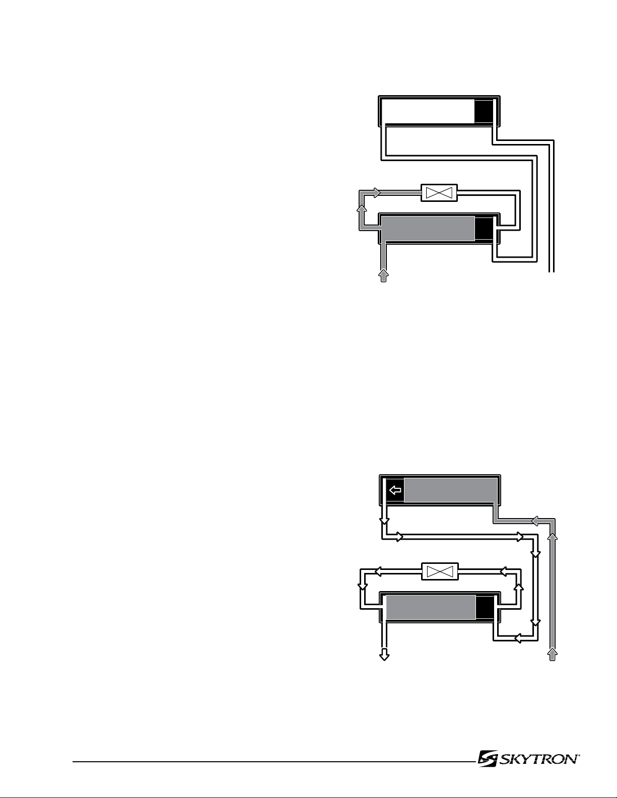
The Kidney Lift cylinders are connected in series so
that both cylinders operate simultaneously.
Hydraulic pressure on one side of the lead piston
causes the piston to move. The piston movement
forces the hydraulic fluid on the other side of the
piston through the system to the other cylinder. This
simultaneously activates the other piston. A bypass
valve is connected to the right cylinder assembly
for initial set-up and adjustment of the kidney lift
system. Refer to figure 3-9 for valve location. Use
the following procedures to bleed or adjust the
system if needed.
a. Bleeding the System
If the hydraulic lines or cylinders have been disconnected from the kidney lift system for any reason,
use the following procedure to bleed the air from
the system.
Page 29
Figure 3-10.
1. Remove the kidney lift top section and begin
the procedure with both pistons in the down position
(chambers A & C) as shown in figure 3-10.
For this procedure you must use the
KIDNEY DOWN switch on the base
cover or remove the micro-switch from
the bottom of the right side kidney cylinder. The KIDNEY DOWN inhibit switch
prevents continued operation necessary
to bleed the system.
2. Make sure the bypass valve is closed (valve
screw tight) and activate "KIDNEY DOWN". The
hydraulic fluid will fill cavity "D" as shown in figure
3-10.
NOTE
3. Open the bypass valve by loosening the screw
in the bottom of the valve and activate "KIDNEY
UP". Hydraulic fluid fills cavity "A" and pushes the
piston into cavity "B". The open valve allows a path
for air to escape from cavity "B" without affecting
the piston in "C". See figure 3-11.
Figure 3-11.
Page 32
Page 30
041905.050
LEFT CYLINDER
RIGHT CYLINDER
D C
B A
BYPASS VALVE (open)
KIDNEY LIFT
DOWN
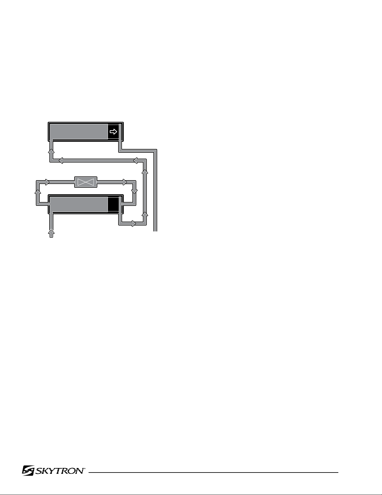
b. Cylinder Adjustment
4. Leave the bypass valve open and activate
"KIDNEY DOWN". Hydraulic pressure keeps the
piston in chamber "C", the hydraulic fluid passes
through the bypass valve and fills cavity "B" pushing
the piston into cavity "A". See figure 3-12.
If either of the kidney lift cylinders reaches the end
of the down stroke before the other one, an adjustment is needed. Use the following procedure to
adjust the system.
1. If the right side bottoms out before the left
side, open the bypass valve and activate "KIDNEY
DOWN" to align the cylinders.
2. If the left side bottoms out before the right
side, activate "KIDNEY UP" to raise the cylinders.
When the cylinders are at the full up position,
open the valve and activate "KIDNEY UP" to align
the cylinders. Close the valve before lowering the
cylinders.
3. When the adjustment is complete, make
sure the cylinders are completely down, activate
"KIDNEY DOWN" and tighten the valve.
4. Make sure to re-install the micro-switch and
re-adjust it as necessary.
Figure 3-12.
5. Repeat steps 3 and 4 as needed to remove
any remaining air in the system.
6. With both pistons in the full down position,
activate "KIDNEY DOWN" to apply full system
pressure and close the bypass valve (tighten the
screw).
Page 33
Page 31
CAPACITOR/
RECTIFIER
BOX
BATTERIES
+
-
CN4
PUMP
HN4
HN3
HN2
15A
HN1
HN9
120 VAC TO
TRANSFORMER
22 VAC FROM
TRANSFORMER
SOLENOID
COIL 24VDC
MINI-VALVES
CN2
CN11
BUZZER
AUXILIARY
SWITCHES
CN10
CN7
CN1B
CN1A
CN8
RELAY BOX
HN8
HN7
TO
RETURN
CIRCUIT
PENDANT
CONTROL
POWER
CORD
FOOT
CONTROL
CONNECTOR
MAIN
POWER
SWITCH
BATTERY
INDICATOR
POWER CORD
BASE CONNECTOR
CN3
CN2
CN1B
CN1A
HN10 HN11
HN5
+
-
CIRCUIT
BREAKER
041905.051
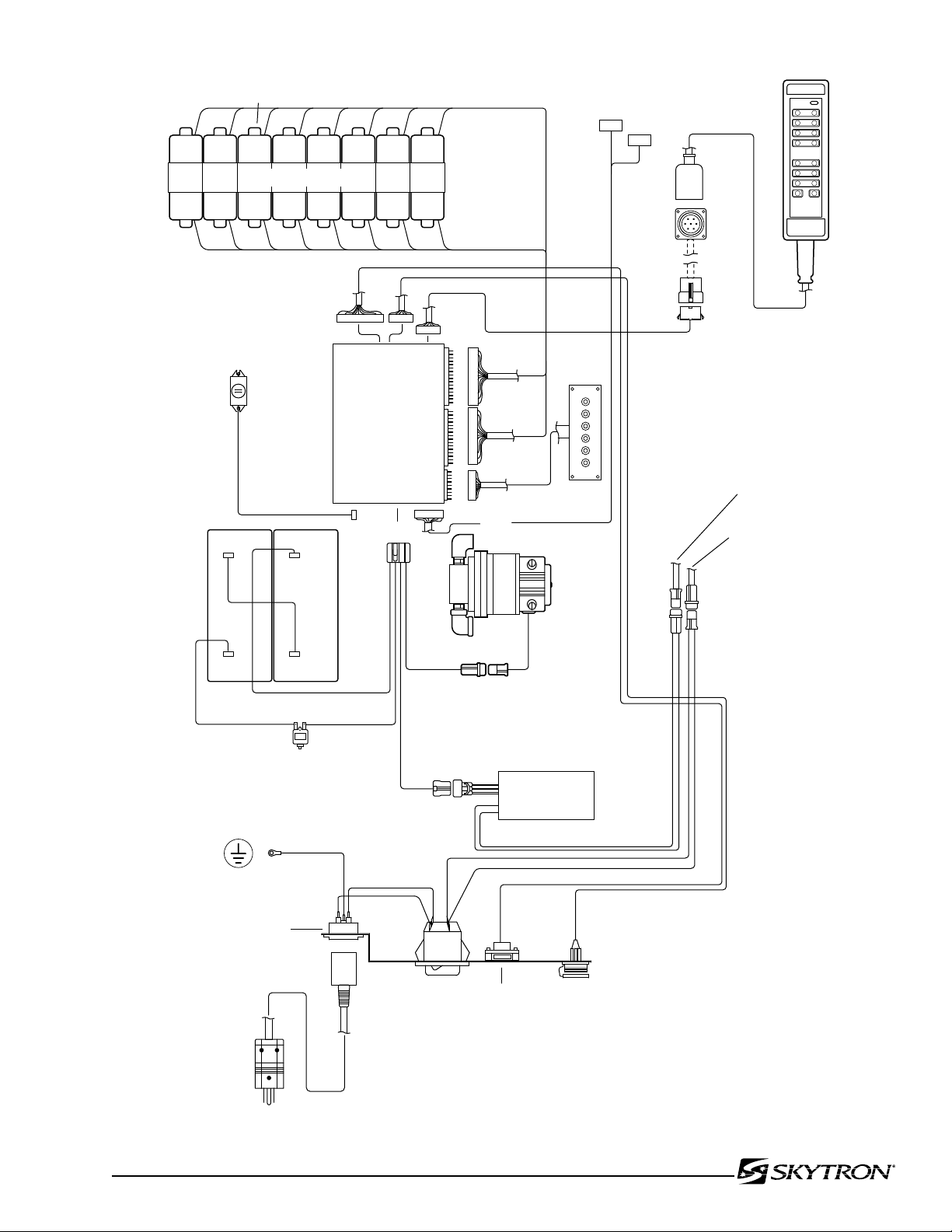
Figure 4-1. Electrical Circuit Block Diagram
Page 34

Page 32
SECTION IV ELECTRICAL SYSTEM
4-1. General
The complete electrical system (with the excep-tion
of the hand-held pendant control and the return
circuit micro-switches) is contained within the base
of the table. The pump motor and the hydraulic
valves are controlled electrically with the pendant
control.
The electrically operated functions are as follows:
- ELEVATION - Up and Down
- TRENDELENBURG - Head up and down
- LATERAL TILT - Right and left
- BACK SECTION - Up and Down
- LEG SECTION - Up and Down
- FLEX / REFLEX
- KIDNEY LIFT - Up and down
4-2. Components
Refer to figure 4-1 for the relationship of the electrical components.
a. Wires, Connectors, Switches, Fuse - These
provide the path for the various electrical circuits.
b. Relay Box - Contains the step down transformer, full wave rectifier, micro-processor and relay
switches. The relay switches are activated by the
pendant control signal to the micro-processor and
in turn energize the solenoids.
c. Hand-Held Pendant Control - Contains circuit
board mounted switches and a micro-processor
which activate the relay box. Operates on 5 VDC.
d. Solenoids - These electrically open and
close the hydraulic ports of the mini-valve to direct
the fluid to the correct cylinders. They operate on
24 V DC.
e. Motor/Pump Assembly - 24 V DC motor with
internal thermal protector.
- LEVEL - Return to level
- BEACH CHAIR
- BRAKE UNLOCK - Brake release
The power requirements are 120 VAC, 60 Hz. The
main power on-off switch is an enclosed DPST circuit
breaker type and the power cord is a three-wire,
fifteen foot long, removable, UL listed cord with a
three-prong hospital grade plug.
Page 35
5-1. General
041905.001
BLACK
WHITE
2
1
HN1
SECTION V ELECTRICAL TROUBLESHOOTING
5-3. Main Switch
Page 33
The battery table components operate on 24VDC.
The internal charging system also incorporates
the components to transform the 120VAC input to
24VDC output to the components.
5-2. Troubleshooting Notes
The basic operation of each component will be
defined along with a figure and an explanation
on how to check it out.
Certain defective components could cause the
entire table to stop functioning or only one control
function to stop. It would depend on what part of
the component failed. Other defective components
would only cause one control function to stop.
The following defective components could cause
all control functions to be affected:
a. Motor/Pump Assembly
b. Main Switch Circuit and Wiring
c. Pendant control
The following defective components could cause all
control functions to be affected or only one control
function:
a. Relay Box
b. Pendant Contro l
c. Auxiliary Switches
The component listed below would only affect one
control function:
Solenoid
When troubleshooting an electrical circuit, start at
the problem and work back to the power source.
The main power supply, 120 VAC, 60 HZ, comes
in through the power cord and through the
Power Switch. The Power Switch opens both lines
when in the "OFF" position. The Power Switch is
also a 10 Amp circuit breaker that is used to protect
the complete electrical system.
a. Main Switch Test
The following test will determine if line voltage is
applied to connector HN1, which in turn would supply 120VAC power to the table.
1. Plug the power cord into the 120VAC supply
(wall receptacle) and turn the main switch ON.
2. Disconnect connector HN1. See figure 4-1.
Leave all other connectors connected.
CAUTION
Line voltage (120 VAC) will be measured
in this test. Do not touch uninsulated
connector pins or meter test leads.
3. Use an AC voltmeter capable of measuring
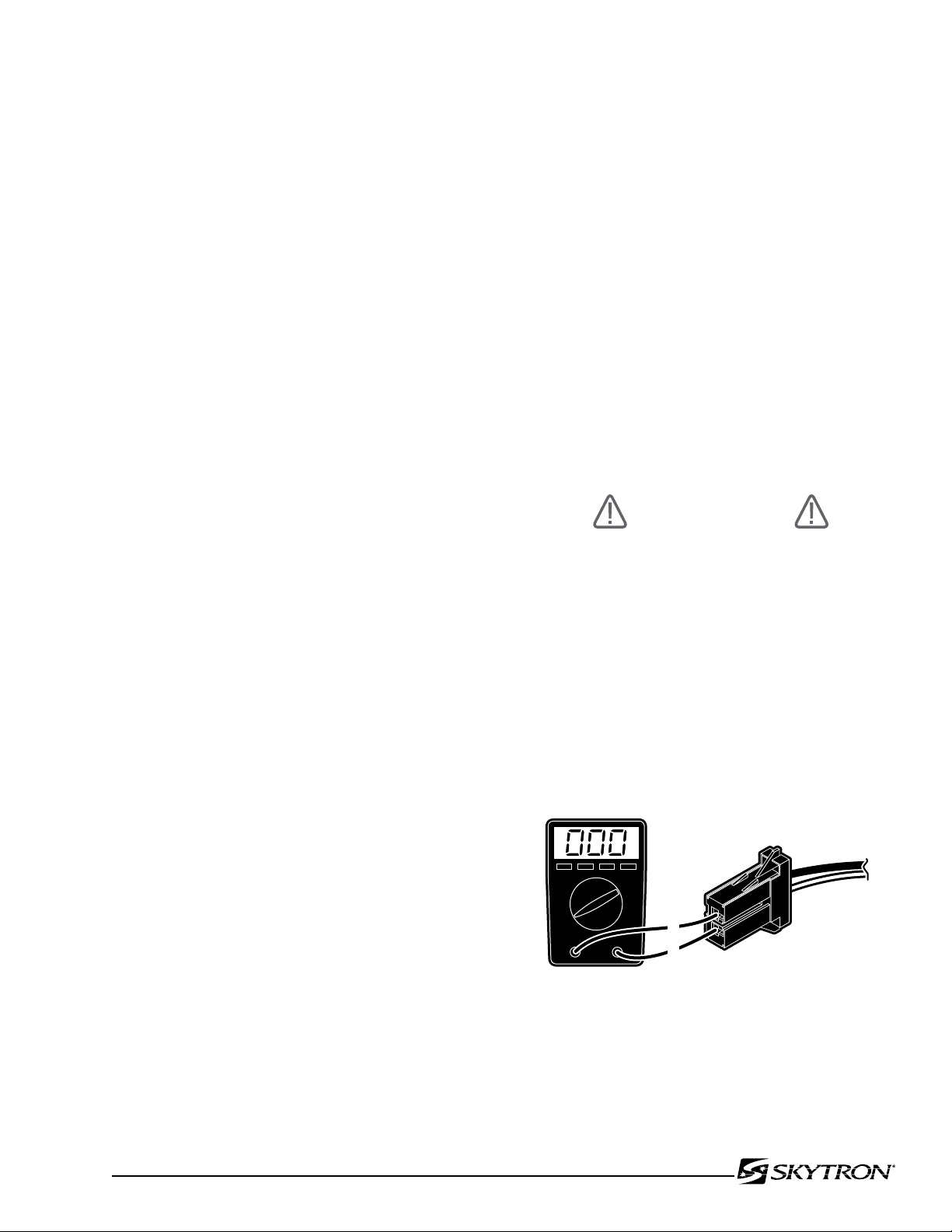
120 VAC and measure the voltage between pins 1
and 2 (black and white wires) located in connector
HN1. See figure 5-1. You should receive line voltage 120 VAC.
NOTE
•Battery table troubleshooting should
begin by switching the operating mode.
For example; if a function fails in the
AC120V mode, switch to the BATTERY
mode. If the function now operates, the
problem is probably located between
the power cord and the relay box. If the
function also fails in battery operation,
use the auxiliary switches. If the function
now operates, the problem is probably
in the pendant control, connectors or
wiring from the pendant control to the
relay box.
•All connector pins are numbered usually
with very small numbers.
Figure 5-1. Connector HN1 Test
Page 36
Page 34
041905.002
BLACK
WHITE
HN1
BASE
CONNECTOR
2
041905.003
BATT
1
BATT
2
+
-
+
-
b. Test Results
If the correct voltage is obtained, everything is
good up to this point and the problem would have
to be in another area. If you do not receive the
correct measurements, the problem would have
to be in the wires, Power Switch, Power Cord, or
main electrical Power Cord connector (3 pin twist
lock connector).
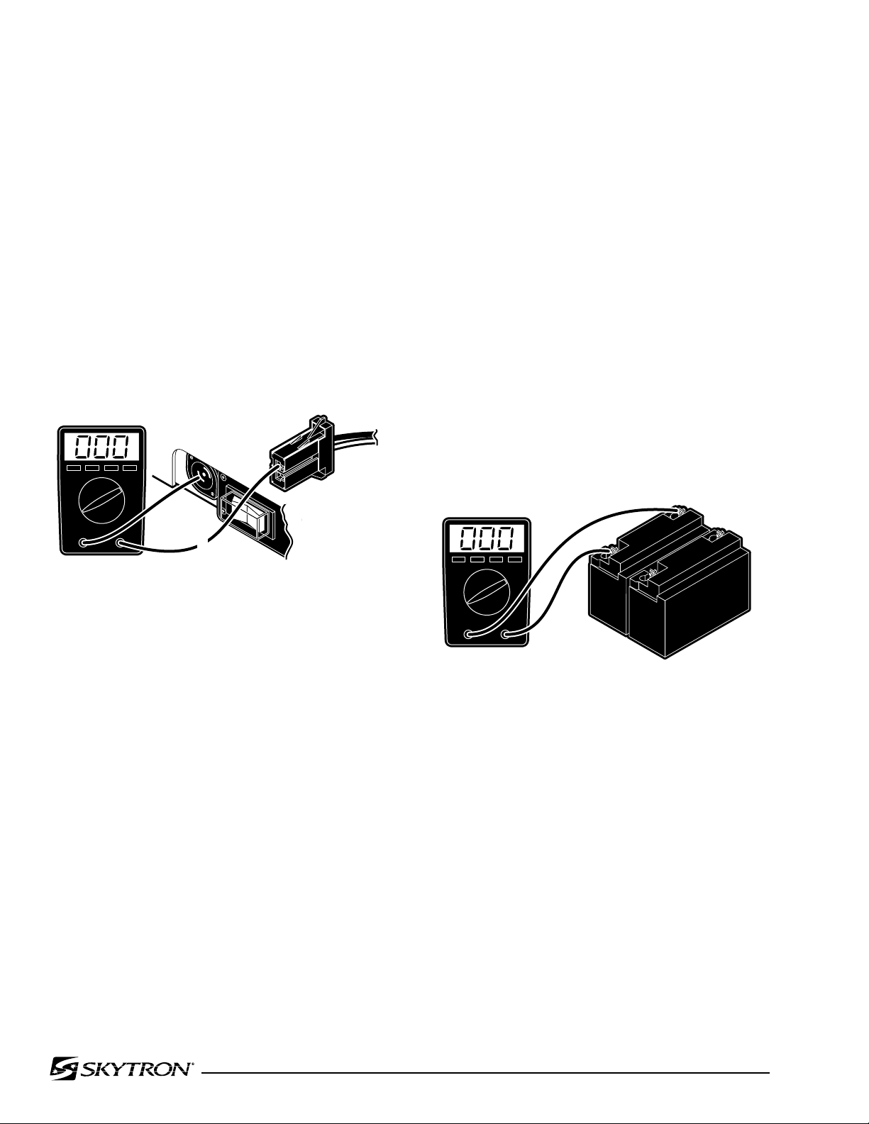
Check the continuity from the power cord base
connector, through the switch and wiring to connector HN1. Remove the power cord, disconnect
HN1 (black and white wires), and test as shown in
figure 5-2.
a. Battery System Test
1. Disconnect the main power cord and using
a DC voltmeter, test each individual battery at its
terminals. Meter should read 12VDC ± 1V.
2. To accurately test the batteries, they must
be tested under a full load. Disconnect the main
power cord and make sure all other connectors are
connected.
3. Turn BATTERY power ON and elevate the
table to its full up position.
4. Continue to press the TABLE UP button on the
pendant control so that the pump motor continues
to run and using a DC voltmeter, check the voltage
drop of each battery individually. See figure 5-3.
5. Meter should read 12VDC ± 1VDC.
Fig. 5-2. Base Connector to HN1 Continuity Test
5-4. Batteries
The BATTERY operating mode is powered by two
12 volt batteries connected in series to provide the
24 volt operating power.
The battery system voltage should be 24VDC at a
range of 22VDC to 26VDC. If the battery charge
level falls below 23.5 volts the BATTERY operation
indicator on the pendant control will blink indicating
that the batteries require recharging. The built-in
charging system automatically keeps the batteries at the proper charge level when the AC120V
operating mode is ON. The charging system will
operate while the table is being operated in the
AC120V mode.
Figure 5-3.
b. Test Results
A reading of 11 volts or below indicates the battery
needs charging.
After batteries have been fully charged, repeat the
full load test. If either battery's voltage drops below
11VDC it should be replaced.
Page 37
041905.004
BROWN
RED
HN2
3
1
041905.052
RED
BROWN
HN2
HN3
1
2
5
2
HN3 CONNECTOR WIRE COLORS
1. PURPLE
2. BLACK
3. YELLOW
4. GRAY
5. ORANGE
5-5. Capacitor / Rectifier / AC120V Transformer
The Capacitor / Rectifier Unit contains the battery
charging system as well as the components for
AC120V operation (except the transformer).
a. Transformer Test
1. Confirm 120VAC input at HN1 using Main
Switch test in 5-3a.
2. Connect HN1, disconnect HN2 (brown and
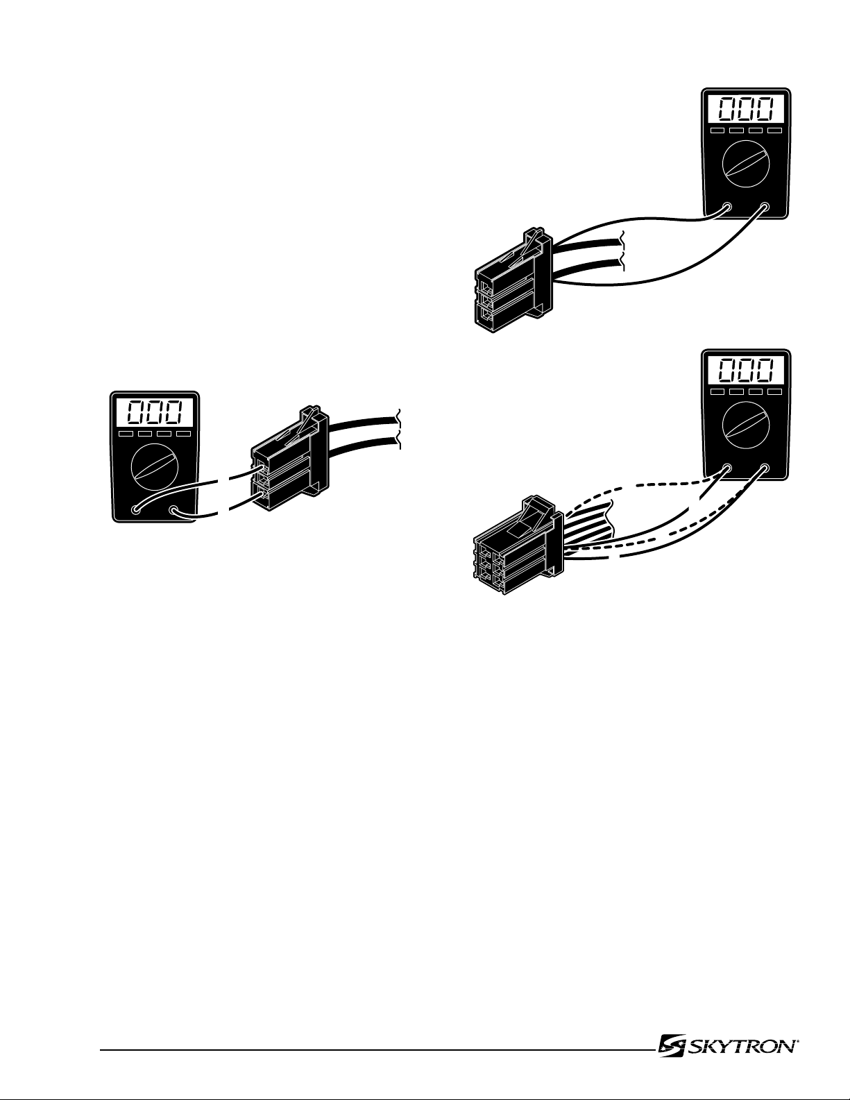
red wires) and using an AC voltmeter, test the
transformer output at HN2. See figure 5-4.
3. Meter should read 22VAC.
Page 35
Figure 5-4. Connector HN2 Test
b. Test Results
If the correct voltage is obtained, everything is
good up to this point and the problem would have
to be in another area. If you do not receive the
correct measurements, the problem may be in the
wires, connectors, or transformer. The transformer
is located in the rear of the base under the stainless
steel base cover. The stainless steel cover will have
to be disconnected and lifted from the base for access to the transformer for further testing.
c. Capacitor / Rectifier Unit Test
1. Make sure all connectors are connected,
connect the power cord and turn AC120V operation ON. Test connectors HN2 and HN3 using a
voltmeter. See figure 5-5.
Figure 5-5. Connector HN3
2. Test connector HN2 at pins 1 (red) and 3
(brown). Meter should read AC23V.
3. Test connector HN3 at pins 1(purple) and 2
(black, ground). Meter should read DC30V.
4. Test connector HN3 at pins 5 (orange) and
2 (black, ground). Meter should read DC27V.
d. Test Results
If you do not receive the correct readings, the connectors, wires, or the Capacitor/Rectifier Unit may
be defective.
Page 38
Page 36
041905.005
1
11
CN3
NOTE
Normal charging time for a fully discharged battery is approximately 8
hours.
e. Charging Indicator Test
Charging Indicator contains 10 LEDs, 3 red, 4 yellow and 3 green.
All Indicators illuminated indicates full charge.
Indicators flash when charging is in process.
The following list shows the battery charge level as
indicated by the lighted LED's:
3 green 100% -Fully charged
2 green 89%
1 green 78%
4 yellow 67%
3 yellow 56%
2 yellow 45% -Needs Charging (BATT
indicator on pendant will flash)
1 yellow 34% -Needs Charging
3 red 23% -Needs Charging
(poor performance)
2 red 12% -Needs Charging
(intermittent performance)
1 red 1% -Needs Charging
(inoperable)
Main Power Switch must be ON and power cord attached and plugged into outlet for charging system
to operate.
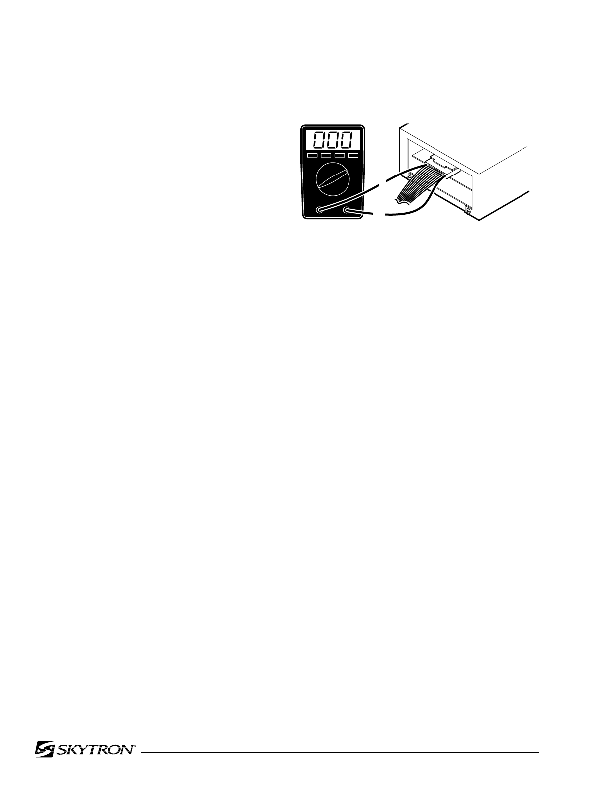
Test output from relay box at CN3 pin 11 common
and pin 1 (lowest charge) meter should read approx.
1.8 VDC. See figure 5-6.
Figure 5-6
5-6. Pendant Control
The Pendant Control is part of the solid state, multiplex, logic control system. The pendant control
contains illuminated, circuit board mounted switches
and a micro processor. The encoded output from
the pendant control is serial bit stream logic.
The output signal is transmitted to the micro processors in the relay box where the logic is decoded
and the appropriate relays for the selected function
are activated.
Pendant Control troubleshooting should begin by
switching the operating mode of the table. For example; if a function fails when operating the table in
the AC120V mode, switch to the BATTERY mode.
If the function now operates, the problem is not the
pendant control and probably is a problem located
between the power cord and the relay box. If the
function also fails when in battery operation, use
the auxiliary switches to operate the function. If the
function now operates, the problem is probably in
the pendant control, connectors or wiring from the
pendant control to the relay box.
Page 39
Page 37
030608.01mj
BLACK 1
GREEN 4
RED 3
WHITE 6
2 BROWN
5 BLUE
7 YELLOW
1 BLACK
3 RED
4 GREEN
7 YELLOW
2 BROWN
6 WHITE
BLUE 5
BASE END PENDANT END
041905.007
CN7
HN8
1
1
LT. GREEN/WHITE
CN7 CONNECTOR HN8 CONNECTOR
1
2
3
4
5
6
7
1
2
3
4
5
6
7
LT. GREEN / WHITE
LT. GREEN
GREEN / BLACK
GREEN / RED
GRAY
GRAY / WHITE
- - -
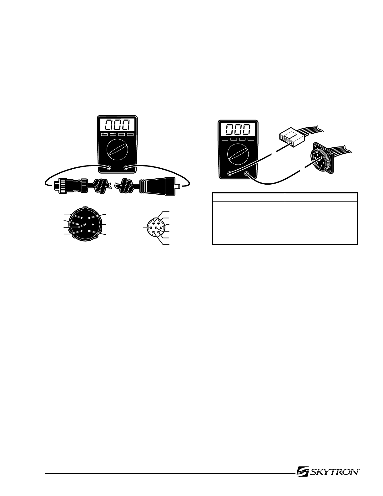
a. Pendant Control Test
There are some serviceable components within
the Pendant Control. The cord is detachable and
can be tested for continuity between the pins on
the connectors. Use the following procedure to test
the pendant control cord. See figure 5-7.
c. Table Connector HN8 Test
If correct readings are received, test the wiring from
the table connector to connector CN7 at the Relay
Box. Disconnect connector CN7 from the Relay Box
and using an ohmmeter, test the continuity between
the corresponding pins in connectors CN7 and the
table connector HN8. See figure 5-8.
Figure 5-7. Pendant Control Test
Disconnect the cord from the table connector and
from the pendant control connector and using an
ohmmeter, test the continuity between the corresponding pins in the connectors.
b. Test Results
If you do not receive the correct readings, the
wiring or connector pins may be faulty.
Figure 5-8. Table Connector Continuity Test
d. Test Results
If the correct readings are not obtained, test the
wiring from the table connector HN8 to connector
HN7 (located under the Trendelenburg cylinder
cover) and from connector CN7 to HN7. Disconnect connector HN7 and using an ohmmeter, test
the continuity between the corresponding pins in
connectors HN7 to CN7 and HN7 to HN8. Refer
to figure 5-8.
If the correct readings are obtained, this part of the
circuit is okay and the problem may be the Pendant
Control or the Relay Box. Contact SKYTRON if all
tests performed indicate that the problem is located
in the Pendant Control.
Page 40
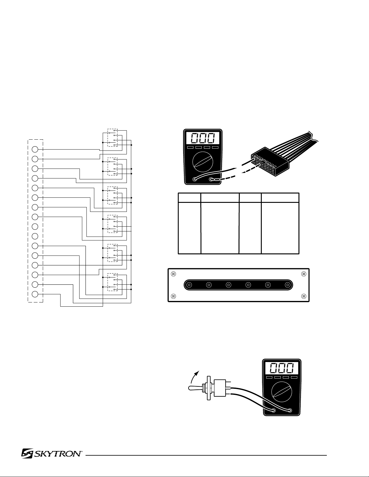
Page 38
041905.008mj
1
SW1
CN2
TABLE UP
TABLE DOWN
TREND
REV TREND
TILT RIGHT
TILT LEFT
BACK UP
BACK DOWN
KIDNEY DOWN
BRAKE LOCK
LEG UP
LEG DOWN
PUMP MOTOR
GROUND
SW2
SW3
SW4
SW5
SW6
2
3
4
5
6
7
8
9
10
11
12
13
14
15
16
PIN NO
1 (A1)
2 (B1)
3 (A2)
4 (B2)
5 (A3)
6 (B3)
7 (A4)
8 (B4)
Red
Green / White
Brown
Yellow
Orange
Green
Brown / White
Blue
9 (A5)
10 (B5)
11 (A6)
12 (B6)
13 (A7)
14 (B7)
15 (A8)
16 (B8)
--
--
Black
Blue / White
Gray
Yellow / White
Red / White
Orange / White
COLOR PIN NO COLOR
CN2
B8/B2 B8/A3 B8/A4 B8/A1 B8/A7 B8/B6
B8/A2 B8/B3 B8/B4 B8/B1 B8/B7 B8/A6
REV
TREND
TILT
RIGHT
BACKUPTABLEUPLEGUPBRAKE
LOCK
TREND TILT
LEFT
BACK
DOWN
TABLE
DOWN
LEG
DOWN
KIDNEY
DOWN
1(A1)
6(B3)
041905.010
5-7. Auxiliary Switches
The following tests will determine if the auxiliary
switches are functioning properly.
a. Switch Test
Disconnect connector CN2 at the Relay Box and
using an ohmmeter check for continuity at the connector pins (pin 1A common) while activating the
appropriate switch. See figure 5-9. Meter should
read 0 ohms.
b. Test Results
If proper meter readings are not received, test the
individual switches as necessary. Using an ohmmeter, test the operation of an individual switch with
the (+) test lead at the center terminal of the switch
and the (-) test lead at the terminal opposite the direction of the switch actuation. Refer to figure 5-10.
Meter should read 0 ohms. If the switches check
out, the problem would have to be in the wires, the
switch circuit board or connector CN2.
Figure 5-9. Auxiliary Switch Connector CN2
Figure 5-10. Auxiliary Switch Test
Page 41
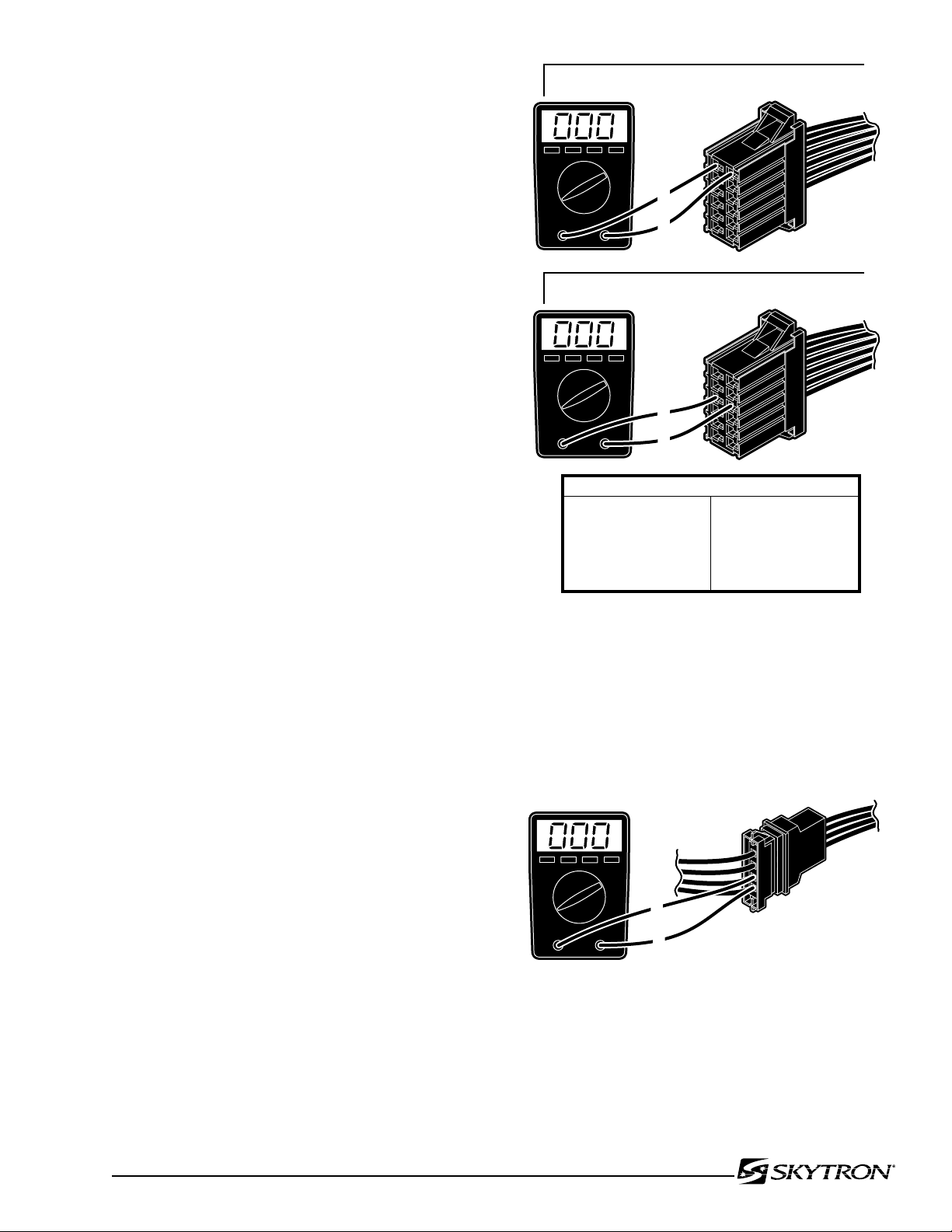
5-8. Relay Box
041905.011
1-RED (+)
2-BLUE (-)
2
1
CN4
BATTERY MODE TEST (main power OFF)
5-PURPLE (+)
6-BLACK (-)
CN4
AC120V MODE TEST (main power ON)
CONNECTOR CN4 COLOR CODE
1
2
3
4
5
6
RED
BLUE
RED
BLACK
PURPLE
BLACK
7
8
9
10
11
12
WHITE
WHITE
YELLOW
GRAY
ORANGE
- - -
6
5
HN4
82205-517
1
2
The power supply is directly connected to the relay
contacts. When these contacts are closed, 24 volts
is supplied to the solenoids which are mounted on
the hydraulic mini-valves. One relay is used to supply
power to the pump/motor and is always activated
no matter what control function is selected. The
brake locking circuit relay is also activated when
any control function other than BRAKE UNLOCK
is initially selected.
Also, inside the relay box is a step-down transformer
and full-wave rectifier which decreases the voltage
to 5-6 volts. This low voltage potential controls the
relays by the use of the hand-held pendant control
buttons. Basically the relays enable a 5-6 volt potential to control the 24 volt circuit.
The following tests will determine if the relay box
is functioning correctly.
Page 39
a. Checking Relay Box Input Power
1. Connect power cord to table. Plug the power
cord into the 120VAC supply (wall receptacle). Disconnect connector CN4, leave all other connectors
connected.
2. Using a DC voltmeter, test input power for
both the BATTERY and AC120V operating modes.
See figure 5-11. Meter should read approximately
24 -28 volts.
b. Test Results:
If you do not receive the correct meter readings,
the problem is in the input wiring, connectors or
components. If the correct readings are obtained,
proceed to the next step.
Figure 5-11. Relay Box Input
c. Checking Output to Pump
1. Make sure all connectors are connected and
activate the AC120V operating mode. See figure
5-12.
Figure 5-12. Output to Pump
2. Test HN4 at pin 1(+) and pin 2(-) with a DC
voltmeter. Meter should read approximately 24-28
volts when any function button is activated. If no
voltage is present, use an ohmmeter to test the
continuity from HN4 to CN4 (red and black wires).
Page 42
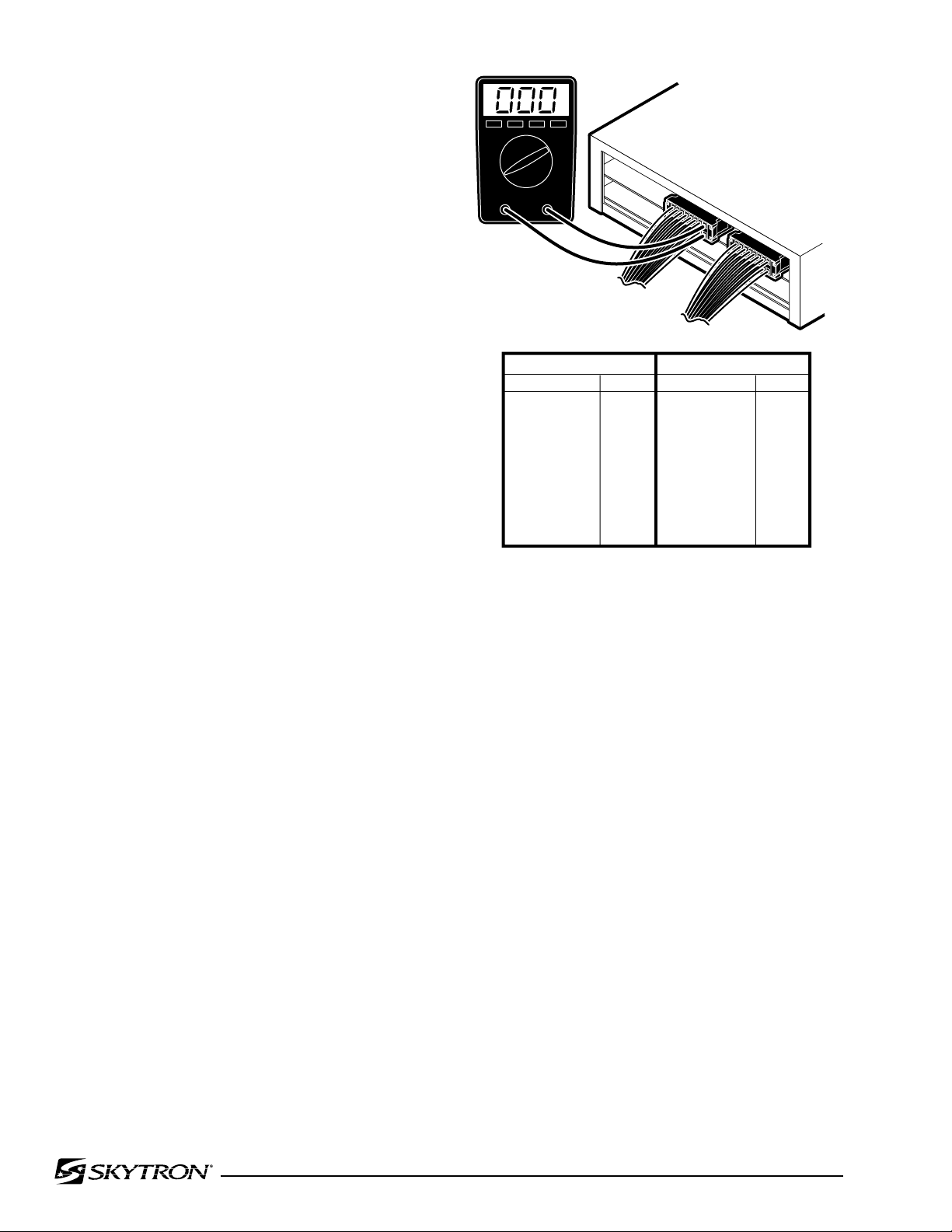
Page 40
041905.012
CN1A
CN1B
CN1A CONNECTOR
FUNCTION PINS
Table Up
Table Down
Trendelenburg
Reverse Trend.
Tilt Right
Tilt Left
Reflex
Flex
1 - 2
3 - 4
5 - 6
7 - 8
9 - 10
11 - 12
13 - 14
15 - 16
CN1B CONNECTOR
FUNCTION PINS
Back Up
Back Down
Kidney Down
Kidney Up
Leg Up
Leg Down
Brake Set
Brake Unlock
1 - 2
3 - 4
9 - 10
11 - 12
13 - 14
15 - 16
17 - 18
19 - 20
d. Checking Output to Solenoids
This test checks the voltage that is used to
energize the solenoids.
1. Activate either BATTERY or AC120V operating mode.
NOTE
•The Brake Lock function is activated
by pressing any function button (except
BRAKE UNLOCK). A timer in the Relay
Box allows continuous output for about
7 seconds. If the brakes are already
locked, no output is provided.
•The BRAKE UNLOCK button activates
another timer in the relay box which
allows continuous output for the brake
release function for approximately 7
seconds. If the brakes are already
released (using the BRAKE UNLOCK
button) no output is provided.
Figure 5-13. Solenoid Output Connectors
2. Test connectors CN1A and CN1B from the
back while attached to the relay box. All connectors
should be connected.
3. Activate each of the pendant control buttons
and measure the output voltage for the corresponding connector pins with a DC voltmeter. See figure
5-13. Meter should read 24 volts.
e. Test Results:
If you do not receive the correct meter readings, the
relay box is defective and should be replaced.
NOTE
•Before deciding the relay box is de-
fective, check the wires and pins in the
connector blocks to make sure they
are not loose or making a bad connection with their mate.
•If the battery power is ON and no table
functions have been activated for 3
hours, the power off circuit will interrupt
the battery power.
f. Checking Output to Pendant Control
The output to the Pendant Control can not be tested
without specialized equipment. If all tests have
been conducted and it appears that the Relay Box
is faulty, contact SKYTRON.
Page 43
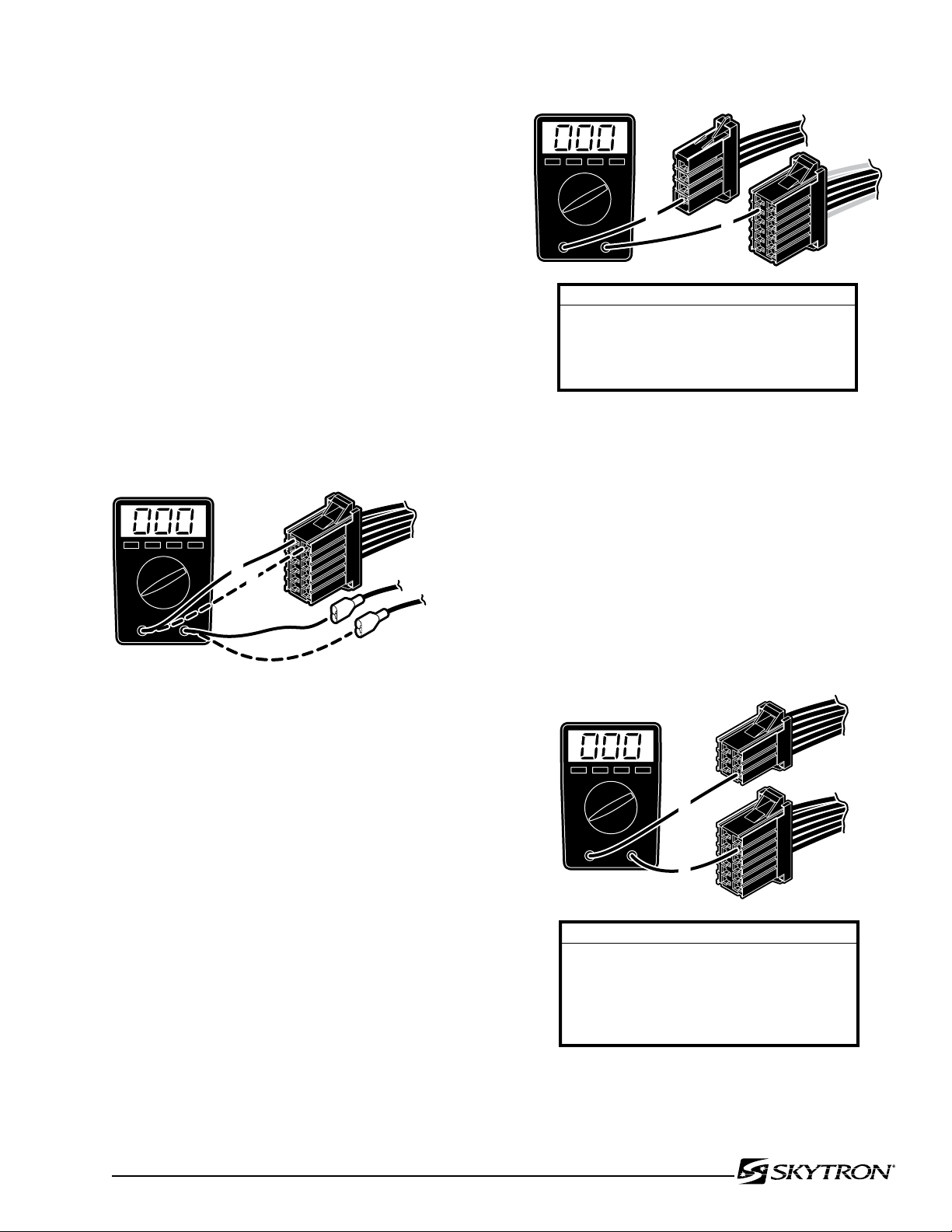
5-9. Main Wire Harness Continuity Tests
041905.013
CN4
(+) RED
(-) BLUE
1
2
HN4
CN4
1
3
WIRE COLOR / PIN NUMBER CODES
HN4 CN4
3
4
7
8
RED
BLACK
WHITE
WHITE
1
2
3
4
041905.014
PIN TEST COMBINATIONS
HN3 CN4
5
6
9
10
11
-
-
-
-
-
1
2
3
4
5
041905.015
CN4HN3
1
5
If correct meter readings are not received in tests
between components, before replacing the components, test the Main Wire Harness to be sure
all connectors and wires are making a good connection.
a. CN4 to Batteries Test
1. Disconnect connectors CN4 and the (+) and
(-) connectors from the batteries. Leave all other
connectors connected.
2. Using an ohmmeter, test for continuity between pin 1 of CN4 and battery (+) connector. Also
test between pin 2 of CN4 and battery (-) connector.
See figure 5-14.
Page 41
Figure 5-15.
Figure 5-14.
NOTE
The 15 amp battery protection circuit
breaker is in the line between CN4 pin
1 and the battery connector. Test the
continuity of the circuit breaker if correct
meter reading is not received.
b. CN4 to Pump Test
1. Disconnect connectors CN4 and HN4. Leave
all other connectors connected.
2. Using an ohmmeter, test for continuity between the pins of CN4 and pins on HN4. See figure
5-15.
c. CN4 to Capacitor / Rectifier Unit Test
1. Disconnect connectors CN4, and HN3. Leave
all other connectors connected.
2. Using an ohmmeter, test for continuity between pins of CN4, and HN3. See figure 5-16.
Figure 5-16. CN4 and HN3
Page 44
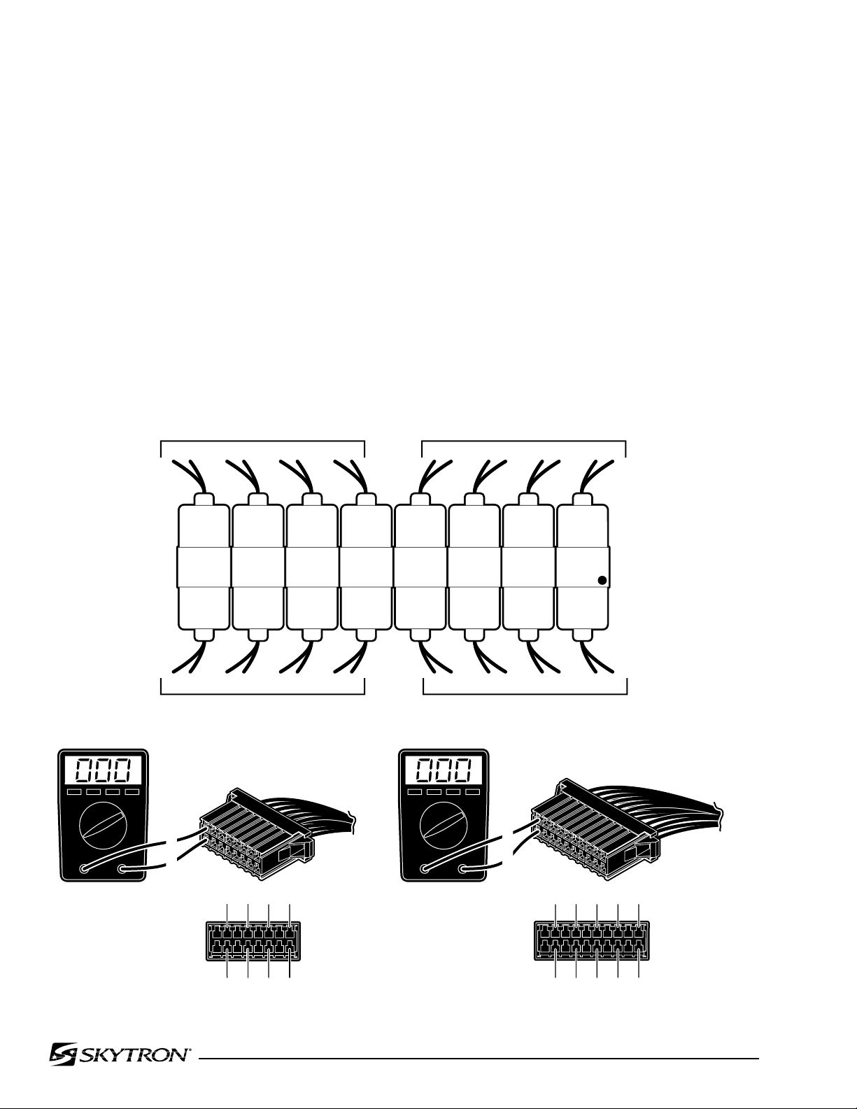
Page 42
041905.016
ELEVATION
Up
Down
TREND.
Reverse
Trend.
Trend.
LATERAL
TILT
Right
Left
FLEX
Reflex
Flex
BACK
SECTION
Up
Down
Down
Up
KIDNEY
Up
Down
BRAKE
Unlock
Lock
LEG
SECTION
1 2 5 6
CN1A
9 10 13 14 1 2 15 16 11 12 19 20
3 4 7 8 11 12 15 16 3 4 13 14 9 10 17 18
CN1B
CN1A
CN1B
1
2
19
20
17
18
15
16
13
14
11
12
9
10
7
8
5
6
3
4
1
2
CN1B
1
2
15
16
13
14
11
12
9
10
7
8
5
6
3
4
1
2
CN1A
BLUE DOT
5-10. Solenoids
The solenoids are energized by 24 volt potential
that is controlled by the relay box. The solenoid
windings are protected from excessive heat by an
internal thermal fuse that will open after approx.
7 minutes of continuous operation. The solenoid
must be replaced if the internal thermal fuse has
been blown. The solenoids are mounted directly
on either side of the hydraulic mini-valves and
push the spool valve in one direction or the other
depending upon which solenoid is activated.
a. Solenoid Test
The resistance of the solenoid coil can be checked
out using an ohmmeter R x 1 scale.
1. Disconnect connectors CN1A and CN1B.
Measure the resistance between the two pins
at the connector for the solenoid in question as
shown in figure 5-17. Polarity of meter leads is not
important.
2. The meter should read approximately 16
ohms at room temperature.
3. Measure the resistance between either
pin and ground.
4. Meter should read infinity.
b. Test Results:
If the solenoid does not check out with the meter,
it is more than likely defective and must be
replaced.
Figure 5-17. Solenoid Test
Page 45
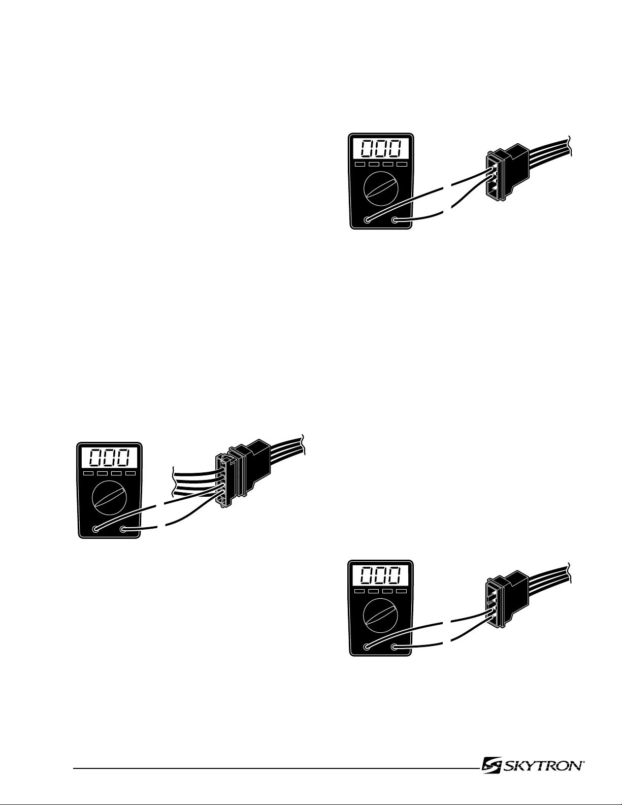
NOTE
HN4
82205-517
1
2
041905.018
HN4
3
4
041905.019
HN4
1
2
Whenever there are several components
of the same type, a defective unit
can also be detected by substituting
a known good unit or wire connector.
In some cases this may be faster than
using a multi-meter.
5-11. Motor/Pump Assembly
The hydraulic pump motor is a thermally protected
24 volt DC electric motor. The oil pump unit is attached to the bottom of the motor and is a gear
type displacement pump with a pumping capacity
of .4 liter per min. The Motor/Pump Assembly is
mounted on insulators in the base of the table.
Page 43
1. Turn OFF both BATTERY and AC120V operating modes.
2. Use an ohmmeter to test for continuity between terminals 3 and 4 on the connector HN4.
See figure 5-19.
Figure 5-19. Thermal Protector
a. Motor/Pump Test
1. Make sure all connectors are connected and
activate the AC120V operating mode. See figure
5-18.
2. Test HN4 at pin 1(+) and pin 2(-) with a DC
voltmeter. Meter should read approximately 24-28
volts when any function button is activated. If no
voltage is present, use an ohmmeter to test the continuity from HN4 to CN4 (red and black wires).
Figure 5-18. Motor Input Voltage
3. The Thermal Relay should reset itself after
approximately one minute.
4. The Thermal Relay should activate after
1-1/2 to 2 minutes of continuous pump operation.
c. Motor Resistance Test
The motor can be statically checked for resistance
using an ohmmeter. This test is not 100% accurate
because you are checking the motor with very low
voltage from the meter and without any load.
1. Using an ohmmeter R x 1 scale, measure
the resistance between the pins 1 and 2 of HN4.
See figure 5-20.
2. The meter should read 1 to 2 ohms at
room temperature.
3. Measure the resistance between either
pin and ground.
4. Meter should read infinity.
NOTE
If the pump has been activated continuously for 1-1/2 to 2 minutes, the
thermal relay will interrupt the power
to the pump.
b. Thermal Protector Test
The Thermal Protector is built in to the pump motor and is used to interrupt the current flow to the
pump motor to protect it from possible damage due
to overheating.
Figure 5-20. Motor Connector HN4
d. Test Results:
If you do not receive the correct meter readings,
the motor or wiring is defective.
Page 46
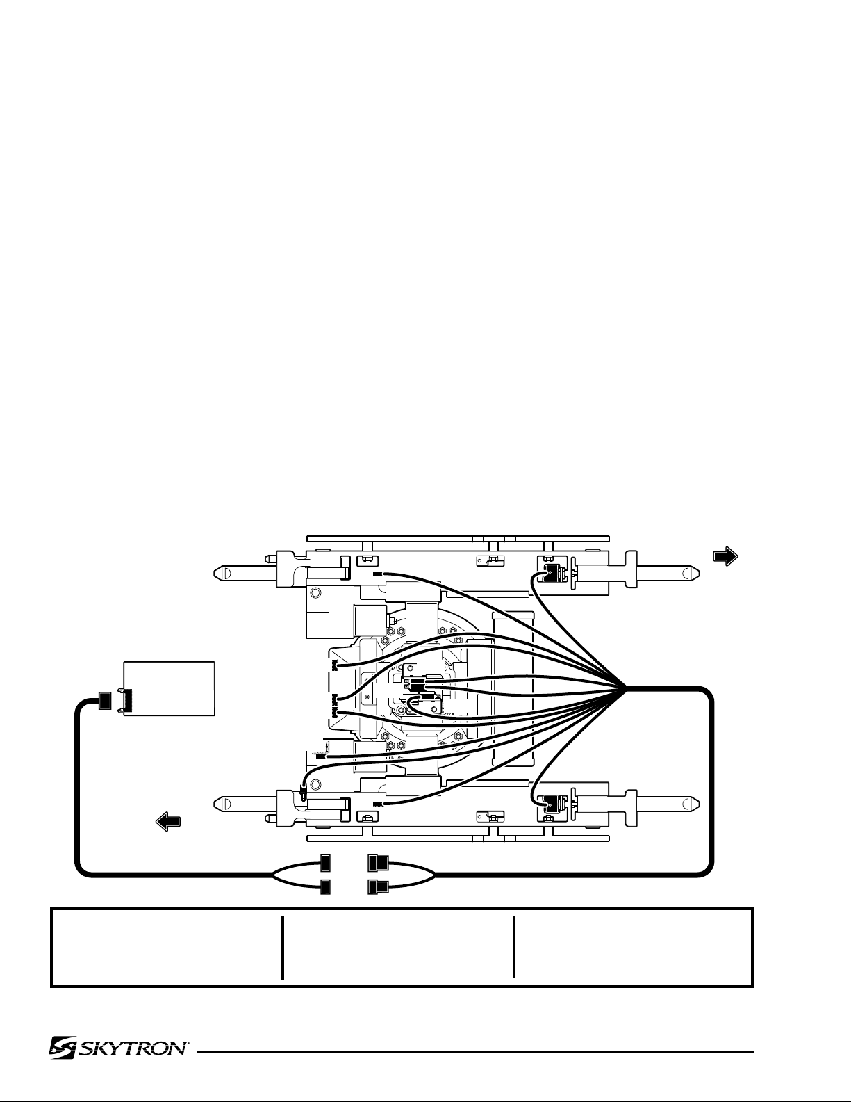
Page 44
041905.053
NS-7
NS-8
CS-3
LS-1
NS-5
NS-6
RELAY BOX
CN-10
HN-10
HN-11
NS-1
LS-2
NS-2
LS-3
NS-3
NS-4
CS-3
LS-1
LS-2
LS-3
Back-Up Inhibit
Kidney Lift Inhibit
Lateral Tilt Inhibit
Trendelenburg Inhibit
NS-1
NS-2
NS-3
NS-4
Trendelenburg
Reverse Trendelenburg
Lateral Tilt (Left)
Lateral Tilt (Right)
NS-5
NS-6
NS-7
NS-8
Back Section (Back-Down Level)
Back Section (Back-Up Level)
Leg Section (Leg-Down Level)
Leg Section (Leg-Up Level)
BACK SECTION
LEG SECTION
5-12. Return-to-Level / Positioning Inhibit
Micro-Switches.
The return-to-level feature is activated by a single
button on the pendant control and automatically
levels the major table functions, lateral tilt, Trendelenburg, back section, and leg section.
The kidney lift has a back section-up inhibit switch
to prevent the table back section from damaging the
kidney lift when the lift is raised. The back section
still has the capability to be lowered, but will not
raise above horizontal until the kidney lift is completely down. If the back section is raised above
horizontal, the system will not allow the kidney lift to
be raised. An audible alarm will sound if the kidney
lift inhibit switch is activated and either function is
activated - raising back section when Kidney lift is
up or raising kidney bridge when back section is
above horizontal.
The lateral tilt and Trendelenburg positioning functions incorporate a safety interlock system which
limits the positioning capabilities. Lateral tilt positioning is limited to 20° if Trendelenburg positioning
exceeds 20°. Likewise, Trendelenburg positioning
is limited to 20° if lateral tilt positioning exceeds
20°. An audible alarm will sound if the positioning
maximums are achieved.
The return-to-level / positioning inhibit system consists of 12 micro-switches, 3 electrical connectors,
and the related wiring. The micro-switches are
mounted on or adjacent to the function they control
and are wired for normally open or normally closed
operation. The micro-switches are either cam or
lever actuated and can be adjusted at the individual
switch mounting brackets.
The micro-switches operate on low voltage, and
control the function circuits (pump/motor and appropriate solenoid valves) when activated by the
pendant control LEVEL button.
The micro-switches are wired to the relay box through
a riser cord and to the 26 pin connector CN10. See
figure 5-21 for switch location and identification.
Figure 5-21.
Page 47
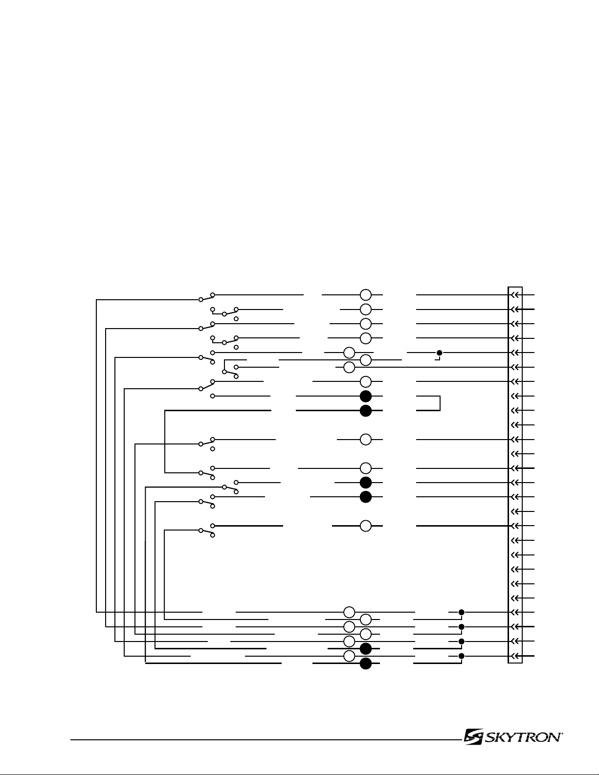
5-13. Troubleshooting
1
2
3
6
5
7
4
1
2
3
5
26
25
24
23
22
21
20
19
18
17
16
15
14
13
12
11
10
9
8
7
6
4
8
9
10
11
13
15
12
14
17
BLACK/WHITE
ORANGE
BROWN
PINK
WHITE
YELLOW/BLACK
RED/WHITE
GREEN/WHITE
BLUE/WHITE
WHITE/BLACK
ORANGE/WHITE
BROWN/WHITE
GREEN
BLUE
YELLOW
RED
NS-1
NS-3
NS-5
NS-7
NS-8
LS-3
LS-1
CS-3
NS-2
NS-4
NS-6
LS-2
PURPLE/WHITE
LIGHT BLUE
BLACK
GRAY
GRAY
PINK/WHITE
PURPLE
5
6
1
3
4
2
16
041905.054mj
(HN10)
(HN10)
(HN10)
(HN10)
(HN10)
(HN10)
(HN10)
(HN10)
(HN10)
(HN10)
(HN10)
CN10
(HN11)
(HN10)
(HN11)
(HN10)
(HN10)
(HN11)
(HN11)
(HN11)
(HN11)
(HN10)
(HN10)
Page 45
If a problem is suspected in the return / positioning
circuits, disconnect the connector CN10 from the
Relay Box to eliminate the circuits. Ensure that all
table functions operate properly using the Pendant
Control. If the functions do not work properly using
the Pendant Control, refer to the appropriate test
section and make all needed repairs before working
on the return circuits.
NOTE
It is normal for the back section to move
up if the LEVEL button is pushed when
connector CN10 is disconnected from
the relay box.
All of the micro-switches are connected to the relay
box via a wiring harness and the micro-switch riser
cord using connectors CN10, HN10 and HN11.
Connectors HN10 and HN11 are located under
the slider shroud in the same area as the hydraulic
hoses. Connector CN10 plugs into the relay box
and is the most convenient location to make circuit
continuity checks. See figure 5-22 for connector
pin locations.
NOTE
Wire colors may vary, however, connection from indicated pins on HN11 to pins
on CN10 remain the same.
Figure 5-22. Return Micro-Switch Test
Page 48
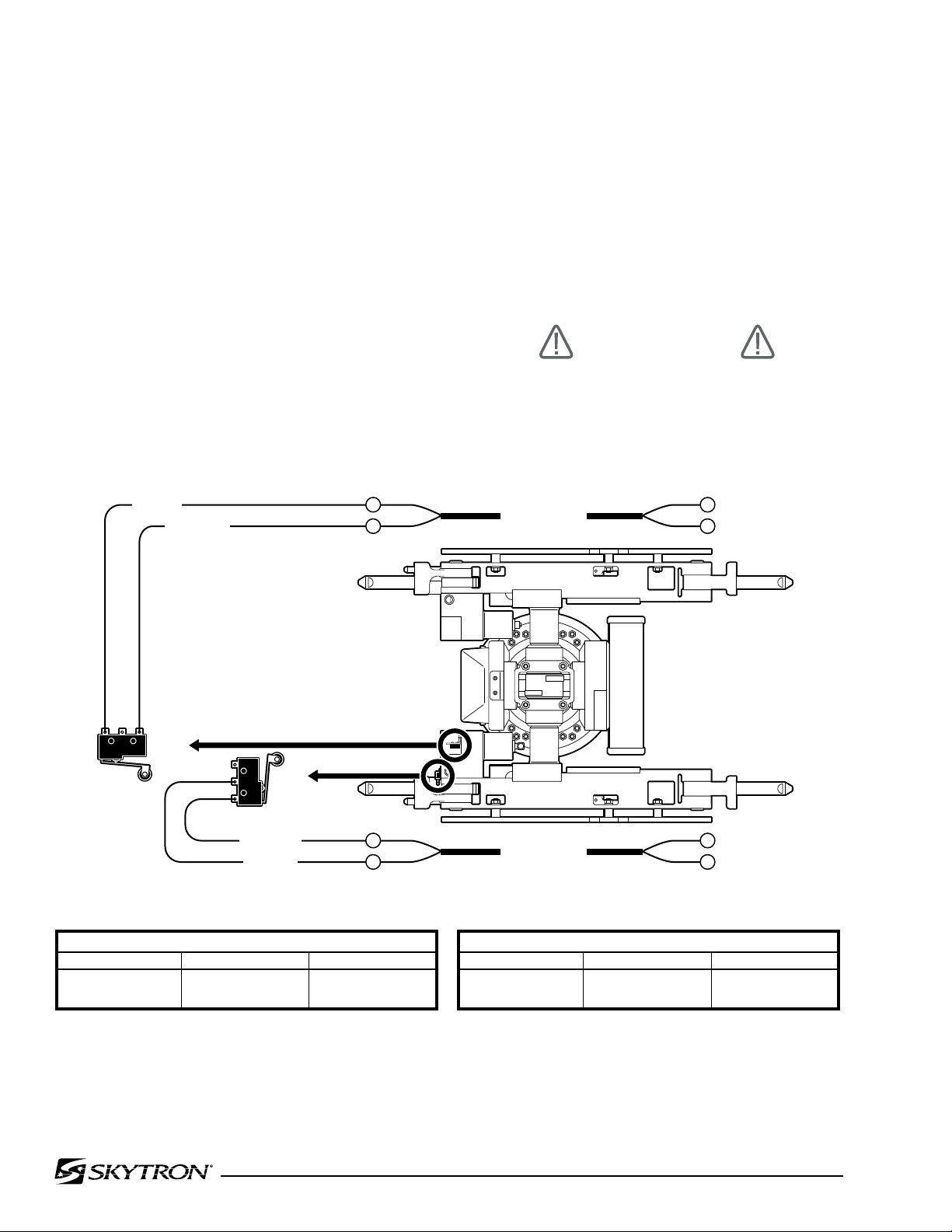
Page 46
041905.055mj
CS-3
LS-1
BACK SECTION LEG SECTION
RISER CORD
RISER CORD
(HN10)
(HN10)
9
15
(CN10)
(CN10)
11
24
ORANGE/WHITE
RED/WHITE
RISER CORD
RISER CORD
(CN10)
(CN10)
17
23
CS-3 BACK UP INHIBIT - TEST AT PINS 11 & 24
When Kidney Lift is UP,
Back Section Can Not go above horizontal.
When Back Section is UP, Kidney Lift Can Not go up.
Table Position
Kidney Lift Down
Kidney Lift Up
Switch Position
Open
Closed
Meter Reading
Infinity
0
LS-1 BACK UP LIMIT - TEST AT PINS 17 & 23
Table Position
Back at level
Back > level
Switch Position
Open
Closed
Meter Reading
Infinity
0
BLUE/WHITE
GREEN/WHITE
(HN10)
(HN10)
11
13
a. Switch Test
Turn Main Power ON, lock the table brakes, and
place the table top sections in a level position with
the Kidney Lift down. Disconnect connector CN10
from the relay box and using an ohmmeter, test the
wiring and switch operation at the appropriate pin
numbers for the micro-switch in question as shown
in figures 5-23 through 5-27.
NOTE
Be sure to isolate the circuit when making continuity checks.
NOTE
If you do not receive the proper continuity results at connector CN10 it does
not necessarily mean the micro-switch
is defective. There could be a problem
with the riser cord between connectors
CN10, HN10 and HN11, or in the wiring
from the switch to connector. Further
tests will have to be made to determine
the exact problem.
CAUTION
Incorrect "Inhibit" micro-switch adjustment may allow component collision
causing table damage and compromise
patient safety.
Adjust CS-3 to close when kidney lift is raised.
Figure 5-23. Back Up Inhibit Switch
Adjust LS-1 to close when back section is raised
above level.
Page 49
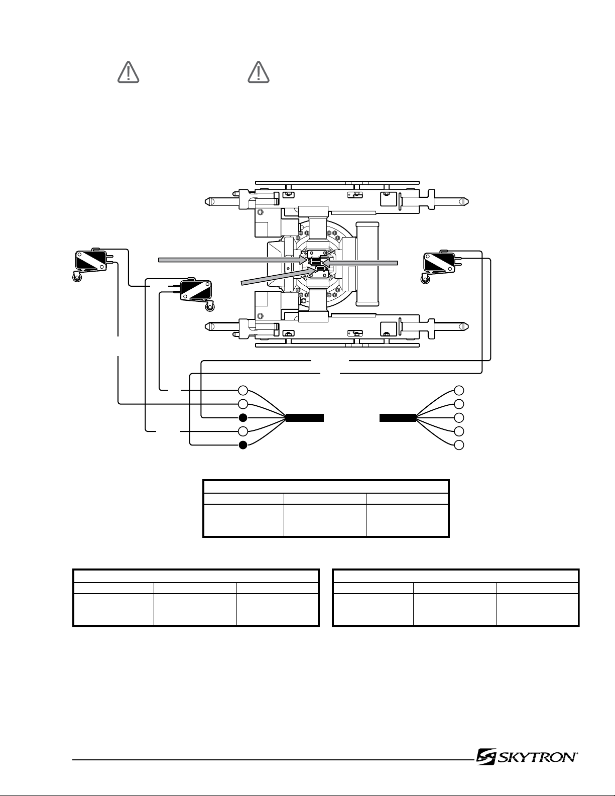
041905.056mj
NS-2 REVERSE TRENDELENBURG - TEST PINS 2 & 23
Table Position
Level
Reverse Trendelenburg
Trendelenburg
Switch Position
Open
Closed
Open
Meter Reading
Infinity
0
Infinity
NS-1 TRENDELENBURG - TEST PINS 1 & 23
Table Position
Level
Reverse Trendelenburg
Trendelenburg
Switch Position
Open
Open
Closed
Meter Reading
Infinity
Infinity
0
LS-2 TILT INHIBIT - TEST PINS 14 & 26
Table Position
Trendelenburg < 20º
Trendelenburg > 20º
Switch Position
Open
Closed
Meter Reading
Infinity
0
BACK SECTION LEG SECTION
CN10
CN10
CN10
CN10
CN10
RISER CORD
RISER CORD
(HN11)
(HN10)
(HN11)
(HN10)
(HN10)
NS-1
LS-2
NS-2
2
1
14
23
26
2
1
12
2
1
WHITE
ORANGE
RED
WHITE/BLACK
PURPLE/
WHITE
BLACK
When table is in Trendelenburg Position,
more than 20º, Tilt is limited to 20º.
When table is in Reverse Trendelenburg Position,
NS-2 brings the top back to level.
When table is in Trendelenburg Position,
NS-1 brings the top back to level.
CAUTION
Incorrect "Inhibit" micro-switch adjustment may allow component collision
causing table damage and compromise
patient safety.
Page 47
Figure 5-24. Trendelenburg Return Switches
Adjust LS-2 to close when Trendelenburg position
reaches 20°
Page 50
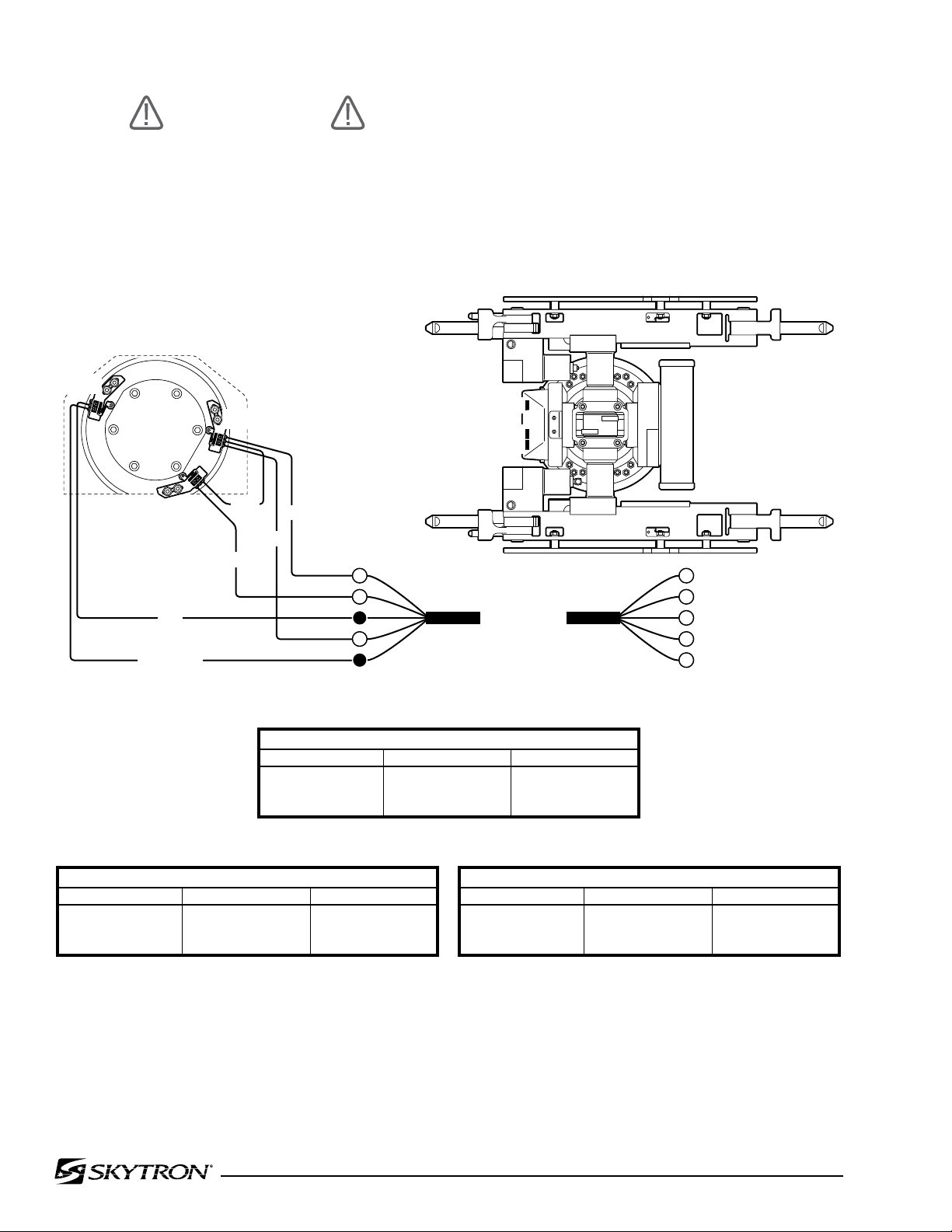
Page 48
041905.057mj
BACK SECTION
LEG SECTION
LS-3
NS-3
NS-4
CN10
CN10
CN10
CN10
CN10
RISER CORD
RISER CORD
(HN11)
(HN10)
(HN11)
(HN10)
(HN10)
4
3
15
24
25
WHITE
YELLOW
GREEN
BROWN
BLUE
YELLOW/BLACK
4
3
14
4
3
LS-3
NS-3
NS-4
NS-3 LATERAL TILT-LEFT - TEST PINS 3 & 24
Table Position
Level
Tilt-Right
Tilt-Left
Switch Position
Open
Open
Closed
Meter Reading
Infinity
Infinity
0
LS-3 LATERAL TILT LIMIT - TEST PINS 15 & 25
Table Position
Level
Tilt-Right > 20°
Tilt-Left > 20°
Switch Position
Open
Closed
Closed
Meter Reading
Infinity
0
0
NS-4 LATERAL TILT-RIGHT - TEST PINS 4 & 24
Table Position
Level
Tilt-Right
Tilt-Left
Switch Position
Open
Closed
Open
Meter Reading
Infinity
0
Infinity
When table is in Tilt-Right Position,
NS-4 brings the top back to level.
When table is in Tilt-Left Position,
NS-3 brings the top back to level.
When table is in Tilt Position more than 20º,
Trendelenburg is limited to 20º.
CAUTION
Incorrect "Inhibit" micro-switch adjustment may allow component collision
causing table damage and compromise
patient safety.
Figure 5-25. Lateral Tilt Return Switches
Adjust LS-3 to close when Lateral Tilt position
reaches 20°
Page 51
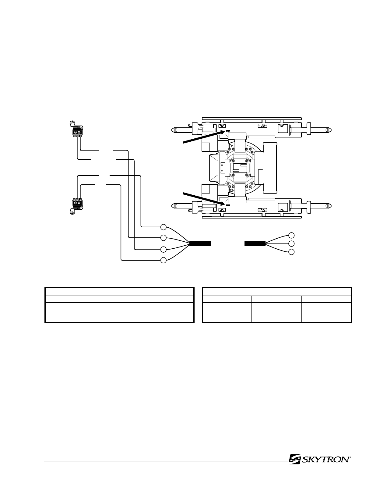
Page 49
041905.058mj
BACK SECTION
LEG SECTION
CN10
CN10
CN10
RISER CORD
(HN10)
(HN10)
(HN10)
(HN10)
5
6
25
NS-5 BACK SECTION DOWN - TEST PINS 5 & 25
Table Position
Level
Back-Down
Back-Up
Switch Position
Closed
Open
Closed
Meter Reading
0
Infinity
0
When the Back Section is Down,
NS-5 brings the Back Section Up to level.
NS-6 BACK SECTION UP - TEST PINS 5 & 6
Table Position
Level
Back-Down
Back-Up
Switch Position
Open
Open
Closed
Meter Reading
Infinity
Infinity
0
When the Back Section is Up,
NS-6 brings the Back Section Down to level.
NS-6
NS-5
PURPLE
BROWN/WHITE
BLUE
PINK
6
7
16
5
NS-5
NS-6
Figure 5-26. Back Section Return Switches
Page 52
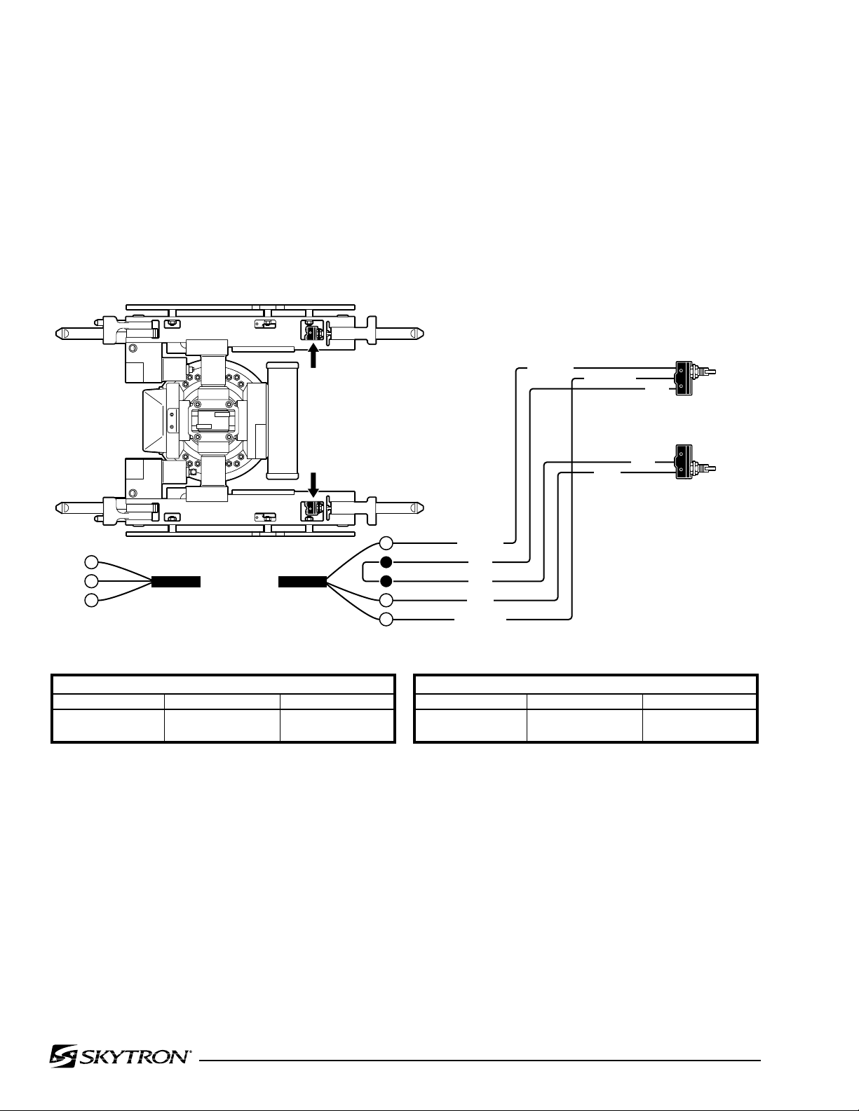
Page 50
041905.059
NS-7 LEG SECTION DOWN - TEST PINS 7 & 26
Table Position
Level
Leg-Down
Switch Position
Open
Closed
Meter Reading
Infinity
0
When the Leg Section is Down,
NS-7 brings the Leg Section Up to level.
NS-8 LEG SECTION UP - TEST PINS 7 & 13
Table Position
Level
Leg-Down
Switch Position
Open
Open
Meter Reading
Infinity
Infinity
When the Leg Section is Up,
NS-8 brings the Leg Section Down to level.
NS-7
NS-8
CN10
CN10
CN10
RISER CORD
(HN10)
(HN10)
(HN11)
(HN11)
(HN10)
7
13
26
BACK
SECTION
LEG SECTION
PINK/WHITE
PINK/WHITE
GRAY
GRAY
GRAY
BLACK
BLACK
BLACK/WHITE
BLACK/WHITE
GRAY
NS-7
NS-8
5
6
10
17
8
Figure 5-27. Leg Section Return Switches
Page 53
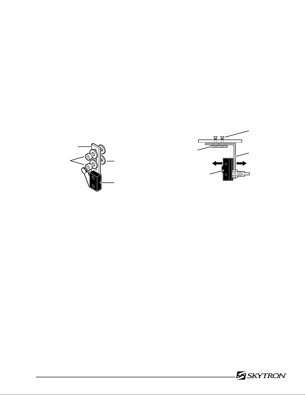
b. Switch Adjustment.
041905.060mj
MICRO-SWITCH
ALLEN BOLTS
MICRO-SWITCH
BRACKET
WASHERS
041905.061mj
LEG SECTION
MICRO-SWITCH
MICRO-SWITCH
BRACKET
COUNTERSUNK
PHILLIPS HEAD
SCREWS
BRACKET
PLATE
If proper readings are not obtained during test or
if table does not properly return to level, use the
following procedure to adjust the switches.
Page 51
1. Apply table brakes and (using a level) level
the table top using the TRENDELENBURG and
LATERAL-TILT function buttons on the pendant
control.
2. For all switches except the Leg Section
switches, carefully loosen the allen bolts securing the switch bracket and adjust the switches as
needed. See figure 5-28.
Figure 5-28. Micro-Switch Adjustment
3. To adjust the Leg Section switches remove
seat section top, loosen the 2 phillips head screws
securing bracket, adjust the switch, tighten the
screws and replace the seat section top. See figure
5-29.
Figure 5-29. Leg Section Micro-Switch
Adjustment.
Page 54
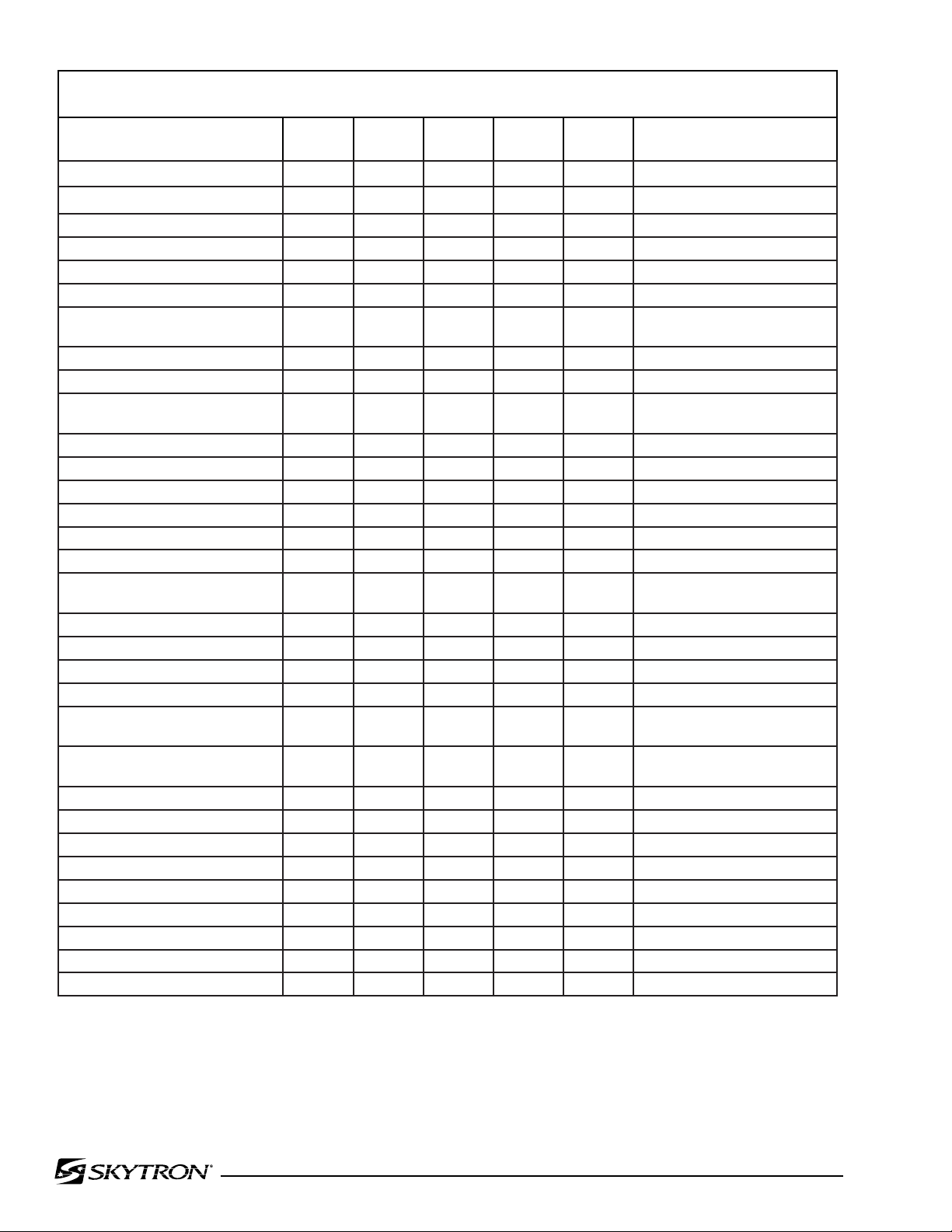
Page 52
APPENDIX: MODEL 6700 SERIES MAINTENANCE MATRIX
COMPONENT
Check for Hydraulic leaks i Pg. 3; 19 (3-1 thru 3-10)
Check Lateral Tilt Housing bolts i Pg. 22
Check Side Rails & Gravity Stops i Pg. 3; 18 (2-5)
Check Velcro i Pg. 3
Inspect Hydraulic Oil level i Pg. 7 (1-1a); 15 (1-3a)
Inspect Power Cord i Pg. 3; 33 (4-1); 35 (5-3b)
Inspect Self-Leveling Brake Pad i Pg. 12 (1.2d, 6); 13 (1.2f); 14
Lubricate Casters i Pg. 19 (2-6)
Lubricate Elevation Column i Pg. 3
Tighten X-ray Top Stand-offs
& apply Blue Loc-Tite
Battery, 12 Volt i Pg. 35 (5-4a)
Back Section Cylinder O-Ring i Pg. 11 (1-2d,1); 24
Trendelenburg Cylinder O-Rings i Pg. 11 (1-2d,1); 22
Lateral Tilt Cylinder O-Rings i Pg. 11 (1-2d,3); 22
Elevation Cylinder O-Rings i Pg. 12 (1-2d,4); 20
Kidney Cylinder O-Rings i Pg. 12 (1-2d,5); 27
Foot-Leg Section Cylinder
O-Rings
Plumbing & Terminal O-Rings i Pg. 13 (1-2f); 29 (3-11)
Brake Pad, Self-Leveling Hard i Pg. 12 (1-2d,6)
Brake Pad, Rubber Soft i Pg. 12 (1-2d,6)
Casters i Pg. 19 (2-6)
Check Valves i Pg. 9 (1-2c); 13 (1-2e); 22
Pendant Control Assembly i Pg. 33 (4-2c); 37 (5-6); 52
Main ON/OFF Switch i Pg. 34 (5-3a)
Power Cord Assembly i Pg. 35 (5-3b)
Power Cord Receptacle i Pg. 35 (5-3b)
Pendant Control Connectors i Pg. 37 (5-6c)
Grounding Lead i
Back Section Micro Switches i Pg. 46 (5-13); 50 (Fig. 5-13a)
Trendelenburg Micro Switches i Pg. 46 (5-13); 48 (Fig. 5-13a)
Leg Section Micro Switches i Pg. 51
Lateral Tilt Micro Switches i Pg. 46 (5-13); 49 (Fig. 5-13a)
1
YEAR2 YEARS5 YEARS7 YEARS
i/r Pg. 3
i Pg. 11 (1-2d,1); 26
10
YEARS
(1-2g)
(3-4)
(5-13b)
i = Inspect
r = Replace
REFERENCE
Page 55
Page 53
APPENDIX: MODEL 6700 SERIES MAINTENANCE MATRIX
COMPONENT
Brake Cylinders i Pg. 12 (1-2d,6)
Emergency Brake Release Valve i Pg. 14 (1-2g)
Pump/Motor Assembly i Pg. 7 (1-1b); 8 (1-2a); 42 (5-
Pressure Relief Valve Assembly i Pg. 7 (1-1c); 8 (1-2b); 15 (1-3c);
Hydraulic Oil System i Pg. 14 (1-2f-g); 20 (3-2,5)
Mini-Valve Spool Valve Return
Springs
Riser Cord Assembly i Pg. 45 (5-12); 46 (5-13); 47
Slider Column i Pg 12 (1-2d,4); 13 (1-2e)
Elevation Shroud Gasket i
Access Cover Gasket i
Labels/Operational Decals i Pg. 4
1
YEAR2 YEARS5 YEARS7 YEARS
10
YEARS
9b); 44 (5-11a)
20 (3-1)
i Pg. 14 (1-2f-g)
(5-13a)
REFERENCE
i = Inspect
r = Replace
Page 56

Grand Rapids, MI 49512 • 1-616-656-2900 • FAX 1-616-656-2906
5085 Corporate Exchange Blvd. S.E.
 Loading...