


ELITE SERIES SURGICAL TABLES
MAINTENANCE MANUAL
MODEL ELITE 6002
INCLUDING BATTERY MODELS
REV 8/05 |
Page 59 |
Page 52
Table of Contents
SECTION I HYDRAULIC SYSTEM ...................................................................................................... |
1 |
||
1-1. |
General........................................................................................................................................... |
1 |
|
1-2. |
Component Operation .................................................................................................................... |
2 |
|
|
a. |
Motor/Pump Operation ............................................................................................................. |
2 |
|
b. |
Pressure Relief Valve .............................................................................................................. |
2 |
|
c. |
Mini-Valves ............................................................................................................................... |
3 |
|
d. |
Mini-valve in Neutral Position ................................................................................................... |
3 |
|
e. |
Mini-Valve Right Port Activated ................................................................................................ |
4 |
|
f. |
Mini-Valve Left Port Activated .................................................................................................. |
4 |
|
g. |
Hydraulic Cylinders (Slave Cylinders) ..................................................................................... |
5 |
|
h. |
Elevation Cylinder Return Circuit ............................................................................................. |
6 |
|
i. |
Brake System........................................................................................................................... |
7 |
|
j. |
Emergency Brake Release ...................................................................................................... |
8 |
|
k. |
Flex/Reflex System ................................................................................................................... |
8 |
1-3. |
Hydraulic Adjustments ................................................................................................................... |
9 |
|
|
a. |
Fluid Level. ............................................................................................................................... |
9 |
|
b. |
Bleeding The Hydraulic System ............................................................................................... |
9 |
|
c. |
Pressure Relief Valve .............................................................................................................. |
9 |
|
d. |
Speed Controls ......................................................................................................................... |
9 |
SECTION II MECHANICAL TABLE ADJUSTMENTS ........................................................................ |
11 |
||
2-1. Back Section Gear Mesh Adjustment ........................................................................................... |
11 |
||
2-2. |
Hydraulic Cylinder Adjustment ...................................................................................................... |
11 |
|
|
a. |
Back Section ........................................................................................................................... |
11 |
|
b. |
Leg Section ............................................................................................................................. |
11 |
SECTION III HYDRAULIC TROUBLESHOOTING ............................................................................. |
12 |
||
3-1. |
Precautions ................................................................................................................................... |
12 |
|
3-2. |
Troubleshooting Notes .................................................................................................................. |
12 |
|
3-3. |
ELEVATION DIAGNOSIS CHART .............................................................................................. |
13 |
|
3-4. |
TRENDELENBURG DIAGNOSIS CHART .................................................................................. |
14 |
|
3-5. |
LATERAL - TILT DIAGNOSIS CHART ........................................................................................ |
15 |
|
3-6. |
FLEX SYSTEM DIAGNOSIS CHART .......................................................................................... |
16 |
|
3-7. |
BACK SECTION DIAGNOSIS CHART ....................................................................................... |
17 |
|
3-8. |
LEG SECTION DIAGNOSIS CHART .......................................................................................... |
18 |
|
3-9. |
BRAKE CIRCUIT DIAGNOSIS CHART ..................................................................................... |
19 |
|
3-10. Flexible Hose Identification and Placement ................................................................................... |
20 |
||
REV 8/05
Although current at time of publication, SKYTRON's policy of continuous development makes this manual subject to change without notice.
Page 53

Table of Contents (continued)
SECTION IV ELECTRICAL SYSTEM .................................................................................................. |
22 |
|
4-1. |
General.......................................................................................................................................... |
22 |
4-2. |
Components .................................................................................................................................. |
22 |
4-3. |
Battery Model Components ........................................................................................................... |
22 |
SECTION V ELECTRICAL SYSTEM TROUBLESHOOTING ............................................................. |
23 |
|
5-1. |
Troubleshooting Notes .................................................................................................................. |
23 |
5-2. |
Main Switch ................................................................................................................................... |
23 |
5-3. |
Pendant Control ............................................................................................................................ |
24 |
5-4. |
Relay Box ...................................................................................................................................... |
25 |
5-5. |
Solenoids ....................................................................................................................................... |
27 |
5-6. |
Motor/Pump Assembly .................................................................................................................. |
29 |
5-7. Return To Level Micro-Switches ................................................................................................... |
31 |
|
5-8. |
Troubleshooting ............................................................................................................................. |
31 |
SECTION VI -6002B- BATTERY MODEL, ELECTRICAL TROUBLESHOOTING .............................. |
36 |
|
6-1. |
General.......................................................................................................................................... |
36 |
6-2. |
Troubleshooting Notes .................................................................................................................. |
36 |
6-3. |
Main Switch ................................................................................................................................... |
37 |
6-4. |
Batteries ........................................................................................................................................ |
37 |
6-5. Battery Charging Box/AC120V Transformer ................................................................................. |
38 |
|
6-6. |
Switch-Over Relay ........................................................................................................................ |
39 |
6-7. |
Pendant Control ............................................................................................................................ |
40 |
6-8. |
Auxiliary Switches ......................................................................................................................... |
42 |
6-9. |
Relay Box ...................................................................................................................................... |
43 |
6-10. Main Wire Harness Continuity Tests............................................................................................. |
45 |
|
6-11. Solenoids ....................................................................................................................................... |
46 |
|
6-12. Motor/Pump Assembly .................................................................................................................. |
47 |
|
SECTION VII ELECTRICAL SYSTEM ADJUSTMENTS .................................................................... |
48 |
|
7-1. |
Relay Box Adjustments Models 6002 & 6002B ............................................................................ |
48 |
WARNING
Indicates a possibility of personal injury.
CAUTION
Indicates a possibility of damage to equipment.
NOTE
Indicates important facts or helpful hints.
Page 54

BASIC RECOMMENDED TOOLS:
1/8". 1/4" STRAIGHT BLADE SCREWDRIVERS #2 PHILLIPS SCREWDRIVER
HYDRAULIC PRESSURE GAUGE SKYTRON P.N. 6-050-02 METRIC ALLEN® WRENCHES 1.5mm-8mm
ADJUSTABLE CRESCENT WRENCH DIGITAL VOLTMETER, TRUE RMS
METRIC OPEN END WRENCHES 7mm-18mm LEVEL (CARPENTERS)
BASIC RECOMMENDED MAINTENANCE PROCEDURES
The basic items notes below should be inspected at a minimal interval period of 6 months (dependant on usage). For optimal usage, safety and longevity of the product, have it serviced only by an authorized Skytron representative with authentic Skytron replacement parts.
• Check Power Cord (if applicable) |
• Inspect Articulating Joints |
• Check Pendant Control (if applicable) |
• Inspect Table Tops |
• Check Oil Level in Reservoir |
• Check Operational Times and Pressure Values |
• Check For Hydraulic Leaks |
• Check Pressure Relief Valve Setting |
• Check All Table Functions |
• Check Side Rails |
• Check Velcro |
• Check Lateral Tilt Housing Bolts |
•Inspect Leg and Head Section detachment mechanisms for proper operation
•Lubricate Elevation Slider Assembly with SKYTRON Slider Grease P/N D6-010-89
•Tighten X-Ray Top Stand-Offs, Use Loc-tite
•Lubricate Casters
•Check brake pads for wear and inspect brake cylinders for proper operation.
Only facility-authorized SKYTRON trained, maintenance personnel should troubleshoot the SKYTRON 6002 Surgical Table. Trouble shooting by unauthorized personnel could result in personal injury or equipment damage.
How to contact us: Skytron
5000 36th St. SE, Grand Rapids, MI 49512 PH: 1-800-759-8766 (SKY-TRON)
FAX: 616-957-5053
Page 55
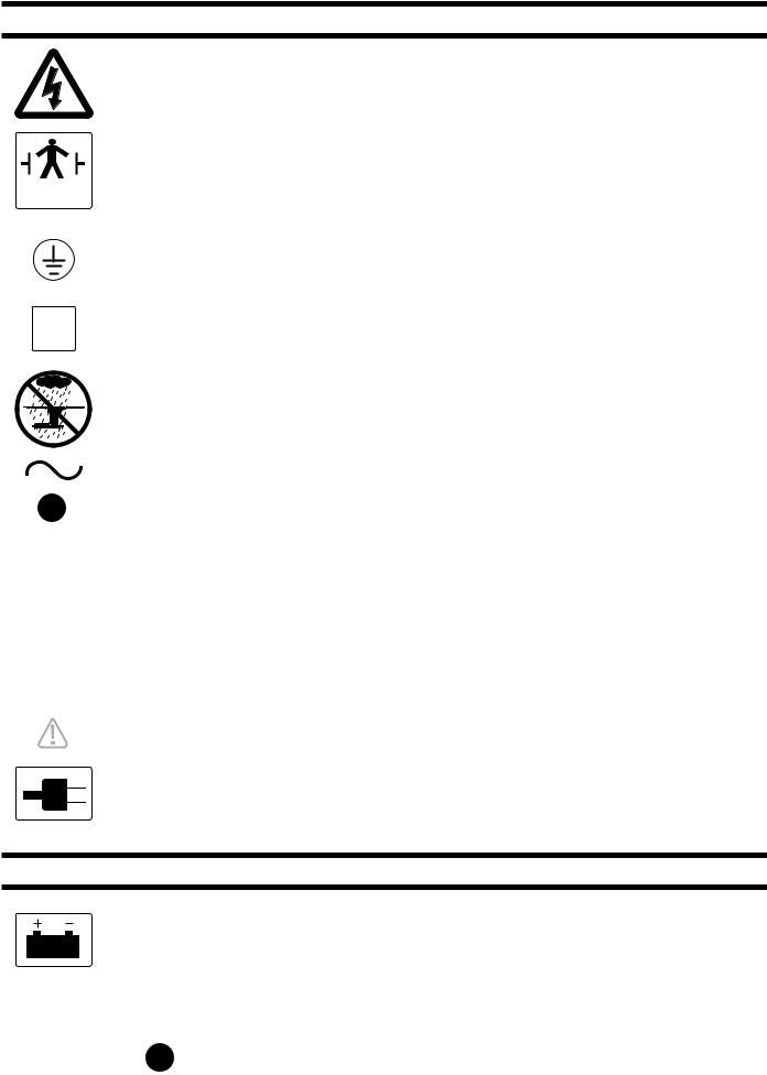
EQUIPMENT LABELS AND SPECIFICATIONS
INDICATES DANGEROUS VOLTAGE, 120 V, 60 Hz
TYPE B
EQUIPMENT
CLASS I DEFIBRILLATION PROOF, TYPE B EQUIPMENTIPX4 RATED. INTERNALLY POWERED EQUIPMENT
PROTECTIVE GROUNDING.
IN ORDER TO ENSURE PROPER GROUNDING RELIABILITY,
THIS TABLE MUST BE CONNECTED TO A PROPERLY GROUNDED HOSPITAL GRADE OUTLET.
N |
CONNECTION FOR NEUTRAL CONDUCTOR SUPPLIED |
|
UNIT TO BE USED ONLY IN SPECIFIED ENVIRONMENTAL CONDITIONS |
|
TEMPERATURE: 15˚ - 30˚ C (60˚ -85˚ F) |
|
HUMIDITY: 30% - 60% RELATIVE HUMIDITY, NON CONDENSING |
|
AC VOLTAGE |
10A |
FUSE (2) 10 AMP FAST ACTING |
IPX4 |
ENCLOSURE CLASS |
V |
VOLTAGE RATING OF THE UNIT |
A |
AMPERAGE RATING OF THE UNIT |
HZ |
FREQUENCY OF THE UNIT |
|
ATTENTION, CONSULT MANUAL FOR FURTHER INSTRUCTIONS. |
|
INDICATES SPECIAL USER ATTENTION. |
|
POWERED BY AC VOLTAGE |
BATTERY MODELS
POWERED BY BATTERY
BATTERY TYPE: SEALED
LEAD ACID 12V, VALVE REGULATED 16AH, 10HR (530W/10MIN)
FUSE: 15A 15 AMP FAST ACTING INTERNAL FUSE
Page 56

6002 Series General Purpose Surgical Table Specifications
 15"
15"
 10"
10"
 19-1/2"
 21-1/2"
 24"
24" 

|
|
|
|
|
|
|
|
|
|
|
|
|
|
|
|
|
|
|
|
|
|
|
|
|
|
|
|
13" |
|
20" |
|||||
|
|
|
|
|
|
|
|
|
|
|
|
|
|
|
|
|
|
|
|
|
|
|
|
|
|
|
|
|
|
|
|
|
|
|
|
|
|
|
|
|
|
|
|
|
|
|
|
|
|
|
|
|
|
|
|
|
|
|
|
|
|
|
|
|
|
|
|
|
|
|
|
75" TOP VIEW
76"
60˚
5-3/4" |
3" |
22" |
|
|
|
90˚ |
|
43" MAX. |
|
|
28" MIN. |
|
|
5-3/4" |
8" |
35-1/2" |
19" |
|
SIDE VIEW |
END VIEW |
|
Electrical Specifications |
|
|
Power requirements |
120 VAC, 60Hz, 300 Watts |
|
Current Leakage |
Less than 100 micro amps |
® |
Power Cord |
15 feet w/hospital grade connector |
|
|
(removeable on battery model) |
Page 57
Page 52

SECTION I HYDRAULIC SYSTEM
1-1. General
Electro-Hydraulic System
The hydraulic system (with the exception of the hydraulic cylinders and hoses) is contained within the base of the table. The hydraulic valves and pump are electrically controlled by the use of a hand-held push button pendant control. The power requirements for the table are 120 VAC, 5 amp, 60 Hz.
The table contains the following components. Refer to the block diagram (figure 1-1) for relationship.
a.Oil Reservoir - Main oil supply. Approximately two quarts.
b.Motor/Pump Assembly - A positive displacement gear type pump provides the necessary oil pressure and volume.
c.Pressure Relief Valve - Provides an alternate oil path when the hydraulic cylinders reach the end of their stroke.
d.Electro/Hydraulic Mini-Valve Assemblies -These direct the fluid to the appropriate hydraulic cylinders.
e.Hydraulic Lines, Fittings, Connections - They provide a path for the hydraulic oil.
f.Hydraulic Cylinders - They convert the hydraulic fluid pressure and volume into mechanical motion.
TRENDELENBURG |
BACK |
|
SECTION |
||
|
||
|
LEG SECTION |
|
|
LATERAL TILT |
ELEVATION
CYLINDER
BRAKE SYSTEM
PLUMBING
TERMINAL
EMERGENCY BRAKE RELEASE
MINI-VALVES
|
|
|
|
|
|
PRESSURE |
|
|
|
|
|
|
RELIEF VALVE |
ELEV |
TREND |
TILT |
FLEX |
BACK |
LEG |
BRAKE |
OIL
RESERVOIR
MOTOR/PUMP ASSEMBLY
Figure 1-1. Hydraulic Block Diagram Model 6002
Page 1
1-2. Component Operation
a. Motor/Pump Operation
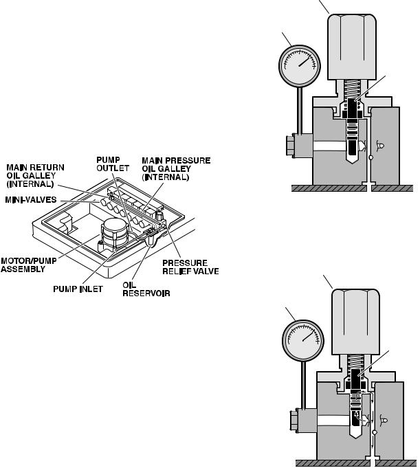
The motor/pump assembly is a gear type pump that provides the oil pressure and volume for the entire hydraulic system. The pump has an inlet side and an outlet side. The inlet side is connected to the reservoir which provides the oil supply. The reservoir has a very fine mesh screen strainer which prevents foreign material from entering the oil system.
The output line of the pump is connected to the main oil galley which is internal and common to all the hydraulic mini-valves and pressure relief valve. Also, common to the hydraulic mini-valves and pressure relief valve is an oil galley that internally connects to the oil reservoir to provide a return path for the hydraulic oil. See figure 1-2.
b. Pressure Relief Valve
The main component of the valve is an adjustable spring loaded plunger that is pushed off from its seat by the oil pressure. The oil then flows back into the reservoir. See figure 1-4 Turning the adjustment nut clockwise increases the amount of oil pressure required to open the valve, and turning it counterclockwise decreases the amount of oil pressure. (See adjustment section for specification.)
PRESSURE RELIEF
ADJUSTMENT NUT
PRESSURE
GAUGE
SPRING LOADED
PLUNGER
Figure 1-3. Pressure Relief Valve Not
Functioning
PRESSURE RELIEF
ADJUSTMENT NUT
PRESSURE
GAUGE
Figure 1-2.
SPRING LOADED
PLUNGER
This device provides an alternate oil path when the hydraulic cylinders reach the end of their stroke and the pump continues to run. If this path were not provided, the pump motor would stall because the oil cannot be compressed. The pressure relief valve is directly connected to the mini-valve bodies and shares both the common internal main pressure oil galley, and the return oil galley, that internally connect to the reservoir. See figure 1-3.
Figure 1-4 . Pressure Relief Valve
Functioning
Page 2
c. Mini-Valves
The operation of the mini-valves is identical for all table functions except the elevation and Single Action Brake circuits. These two hydraulic circuits use a 3-way (single check valve) type mini-valve. All other functions use a 4-way (dual check valve) type mini-valve.
Either type mini-valve is controlled by two pushing type, electrically operated solenoids. The solenoids push the spool valve (located in the lower portion of the valve) one way or the other. This motion opens the main supply galley (which has pump pressure) allowing the oil to flow through the various parts of the mini-valve to the function. The spool valve also opens an oil return circuit which allows the oil to return to the oil reservoir.
The main components of the mini-valve and their functions are listed below:
1.Spool Valve - Opens the main oil galley (pump pressure) to either mini-valve outlet depending on which direction the spool valve is pushed. Also it provides a return path for the oil returning back into the reservoir.
2.Pilot Plunger - There are two plungers in a four-way mini-valve (one in a 3-way mini-valve), one under each check valve. The purpose of the pilot plungers is to mechanically open the return check valve allowing the oil to return back into the reservoir.
3.Check Valve - Two are provided in each fourway mini-valve to seal the oil in the cylinders and oil lines and prevent any movement of the table. One check valve is provided in a 3-way mini-valve.
4.Speed Adjustments - There are two speed adjustments in each mini-valve. They are needle valve type controls which restrict the volume of oil returning back into the reservoir, thereby controlling the speed of the table surface movement. A 3- way mini-valve has only one speed adjustment.
The speed controls are always located in the return oil circuit. This prevents uncontrolled movement of the piston in the slave cylinder due to one side of the piston being loaded with hydraulic pressure and the other side having no load.
Also, by using this control method, it doesn’t matter what size cylinder and piston is used because the speed can be controlled by restricting the return oil. If the pump puts out more volume to a certain slave cylinder than the speed control is allowing to go back to the reservoir, the pressure relief valve provides an alternate path for the pump oil.
d. Mini-Valve in Neutral Position
(No fluid flow) See figure 1-5.
1.Spool Valve Centered - This closes off both oil pressure and oil return galleys.
2.Pilot Plungers Both Closed -The pilot plungers control the opening of the check valves. If they are closed, the check valves must be closed.
3.Check Valves - Both check valves are closed trapping the oil in the cylinder and oil lines.
4.Speed Adjustment - When the mini-valve is in the neutral position, the speed adjustment does not affect anything because there is not any oil flow.
Figure 1-5. Mini-Valve in Neutral Position
Page 3

e. Mini-Valve Right Port Activated
(See figure 1-6)
Slave Cylinder Piston Moves to Left Right Mini-Valve Port is Supply Line Left Mini-Valve Port is Return Line
INLET |
OUTLET |
Figure 1-6. Mini-Valve Right Port Activated
1.Spool Valve - Pushed to the left by electric solenoid. This opens the internal oil pressure galley allowing the fluid to go through the check valve and on to the cylinder. Also, the spool valve opens the oil return line providing an oil path through the internal oil galley back to the reservoir.
2.Pilot Plunger Valve - Left pilot plunger valve is pushed up by the incoming oil pressure mechanically opening the check valve located above it in the return circuit. This action allows the oil from the left side of the slave cylinder to go back into the reservoir. The right pilot plunger valve is not affected in this operation mode.
3.Check Valves - Both check valves are opened in this operation mode. The right check valve is pushed open by the oil pressure created by the pump. The oil then continues to go through the lines and pushes the slave cylinder piston to the left. At the same time, the left check valve is held open mechanically by the pilot plunger providing a return path for the oil through the mini-valve back to the reservoir.
4.Speed Adjustment - The right speed control (output side) does not have any effect in this operation mode because the oil is routed around the speed adjustment through a by-pass valve and then to the output port. The left speed adjustment controls the speed of the table function by restricting the amount of oil going back into the reservoir.
f. Mini-Valve Left Port Activated
(See figure 1-7.)
Slave Cylinder Piston Moves to Right Left Mini-Valve Port is Supply Line Right Mini-Valve Port is Return Line
OUTLET |
INLET |
Figure 1-7. Mini-Valve Left Port Activated
1.Spool Valve -Pushed to the right by electric solenoid. This opens the internal oil pressure galley allowing the fluid to go through the check valve and on to the cylinder. Also, the spool valve opens the oil return line providing an oil path through the internal oil galley back to the reservoir.
2.Pilot Plunger Valve - Right pilot plunger valve is pushed up by the incoming oil pressure mechanically opening the check valve located above it in the return circuit. This action allows the oil from the right side of the slave cylinder to go back into the reservoir. The left pilot plunger valve is not affected in this operation mode.
3.Check Valves - Both check valves are opened in this operation mode. The left valve is pushed open by the oil pressure created by the pump. The oil then continues to go through the lines and pushes the slave cylinder piston to the right. At the same time, the right check valve is held open mechanically by the pilot plunger providing a return path for the oil through the mini-valve back to the reservoir.
4.Speed Adjustment - The left speed control (output side) does not have any effect in this operation mode because the oil is routed around the speed adjustment through a by-pass valve and then to the output port. The right speed adjustment controls the speed of the table function by restricting the amount of oil going back to the reservoir.
Page 4
g. Hydraulic Cylinders (Slave Cylinders)
There are several different types of hydraulic cylinders used in the table that activate the control functions. With the exception of the elevation and brake cylinders, all operate basically the same way. The control functions are listed below: (See figure 1-8.).
Back Section--2, double action cylinders Leg Section--2, double action cylinders Trendelenburg--1, double action cylinder Lateral Tilt--1, double action cylinder Elevation--1, single action cylinder Brakes--4, single action cylinders
TRENDELENBURG |
BACK SECTION |
CYLINDER |
|
CYLINDER |
|
LEG SECTION
CYLINDER
LATERAL TILT
CYLINDER
ELEVATION
CYLINDER
Figure 1-8. Cylinder Placement
1. Back Section and Leg Section Cylinders - The double action cylinders are closed at one end and have a movable piston with hydraulic fluid on both sides. Connected to this piston is a ram or shaft that exits out of the other end of the cylinder. Through the use of either a gear, or clevis and pin arrangement, this ram is connected to a movable table surface.
The movable surface can be moved one way or the other by pumping hydraulic fluid into the cylinder on either side of the piston. Obviously, if oil is pumped into one side of the cylinder, a return path must be provided for the oil on the other side. See figure 1-9.
O-RING O-RING
 PISTON
RAM
HYDRAULIC LINE
Figure 1-9. Back Section Cylinder
2. Trendelenburg Cylinder Assembly - This cylinder / piston arrangement has rack teeth cut into the top of each piston. These teeth mesh with a pinon gear that is connected directly to the table side frames. The pinion gear shaft and table side frames are supported by bearings at either side.
When hydraulic fluid is pumped into one side of the cylinder, the pistons are pushed in one direction, moving the pinion gear and table side frames with them. Oil pressure can be applied to either side of the piston, making the table tilt end for end. See figure 1-10.
TABLE TOP
PINION GEAR
PISTONS
SIDE VIEW
Figure 1-10. Trendelenburg Cylinder Assy.
In order to remove any looseness or play in the table top, the trendelenburg pistons are made in two pieces as shown in figure 1-11. This arrangement eliminates any gear lash between the piston teeth and the table pinion gear due to oil pressure always being present on both sides of the pistons.
OIL PRESSURE |
OIL PRESSURE |
|
SPLIT PISTONS |
TOP VIEW |
REMOVE GEAR LASH |
|
Figure 1-11. Trendelenburg Cylinder Pistons
Page 5

3. Lateral Tilt Assembly - The lateral tilt assembly consists of two cylinders, pistons and connecting rods. The connecting rods attach to the lateral tilt lever which connects to the table side frames. When hydraulic fluid is pumped into one cylinder, the piston and connecting rod pushes the lateral tilt lever which tilts the table top to one side. To tilt the table top in the opposite direction, fluid is pumped into the opposite cylinder. See figure 1-12.
TABLE TOP
LATERAL TILT
LEVER
PISTON CONNECTING PISTON
RODS
Figure 1-12. Lateral Tilt Cylinder Assembly
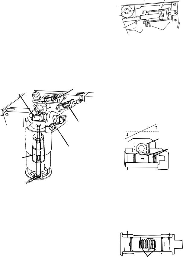
4. Elevation Cylinder - This single action cylinder does not have hydraulic fluid on both sides of the piston. It depends on the weight of the table top assembly to lower it.
The cylinder is set in the center of the elevation main column. The cylinder is elevated by the driven force of the oil pressure. When lowering, the oil that is accumulated in the cylinder is returned to the oil reservoir through the mini-valve due to the table top weight.
A slider support assembly is used to support the weight of the upper table section. A stainless steel shroud covers the flexible hydraulic hoses and slider. See figure 1-13.
Figure 1-13. Elevation Cylinder Assembly
5. Brake Cylinders - The brake cylinders are single action type similar to the elevation cylinder. The movable piston's ram is connected to a brake pad. See figure 1-14. Oil pumped into the top of the cylinder pushes the piston down raising the table base off its casters. An internal return spring on the bottom of the piston, pushes the piston up to return the oil through the mini-valve to the reservoir.
OIL LINE |
PISTON |
|
|
|
RETURN |
|
SPRING |
BRAKE |
RAM |
PAD |
|
Figure 1-14. Single Action Brake Cylinder
h. Elevation Cylinder Return Circuit
Three-way (single check valve type) mini-valves control both the elevation and return circuits. The elevation circuit operation within the mini-valve is identical to the operation of the four-way valves previously described (inlet pressure opens the check valve allowing the oil to enter the cylinder). In the return position, inlet pressure pushes the pilot plunger up and opens the return check valve. See figure 1-15. The open check valve allows a path for the oil in the elevation cylinder to return to the reservoir. When the pilot plunger valve is opened, the continuing pump pressure opens the pressure relief valve which provides a return oil path to the reservoir.
Page 6
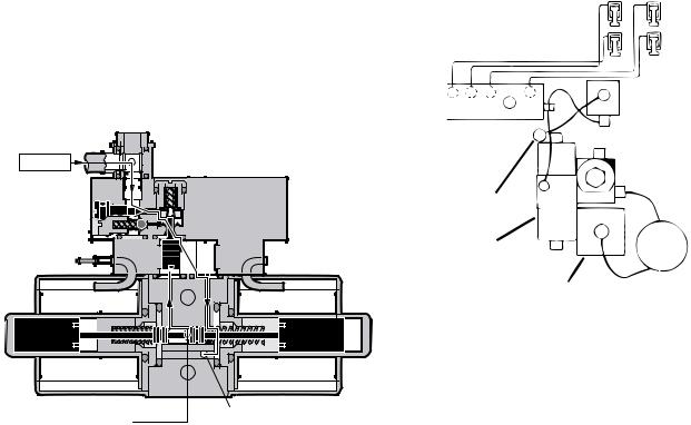
The mini-valve used in the elevation circuit contains only one check valve (all four-way minivalves use two check valves). The check valve is used to trap the oil in the elevation cylinder thereby supporting the table top. When the top is being lowered the check valve is mechanically held open by the pilot plunger through pump pressure.
INLET
|
|
|
|
|
|
|
|
|
|
|
|
|
|
|
|
|
|
|
|
|
|
|
|
|
|
|
|
|
|
|
|
|
|
|
|
|
|
|
|
|
|
|
|
|
|
|
|
|
|
|
|
|
|
|
|
|
|
|
|
|
|
|
|
|
|
|
|
|
|
|
|
|
|
|
|
|
|
|
|
|
|
|
|
|
|
|
|
|
|
|
|
|
|
|
|
|
|
|
|
|
|
|
|
|
|
|
|
|
|
|
|
|
|
|
|
|
|
|
|
|
|
|
|
|
|
|
|
|
|
|
|
|
|
|
|
|
|
|
|
|
|
|
|
|
|
|
|
|
|
|
|
|
|
|
|
|
|
|
|
|
|
|
|
|
|
|
|
|
|
|
|
|
|
|
|
|
|
|
|
|
|
|
|
|
|
|
|
|
|
|
|
|
|
|
|
|
|
|
|
|
|
|
|
|
|
|
|
|
|
|
|
|
|
|
|
|
|
|
|
|
|
|
|
|
|
|
|
|
|
|
|
|
|
|
|
|
|
|
|
|
|
|
|
|
|
|
|
|
|
|
|
|
|
|
|
|
|
|
|
|
|
|
|
|
|
|
|
|
|
|
|
|
|
|
|
|
|
|
|
|
|
|
|
|
|
|
|
|
|
|
|
|
|
|
|
|
|
|
|
|
|
|
|
|
|
|
|
|
|
|
|
|
|
|
|
|
|
|
|
|
|
|
|
|
|
|
|
|
|
|
|
|
|
|
|
|
|
|
|
|
|
|
|
|
|
|
|
|
|
|
|
|
|
|
|
|
|
|
|
|
|
|
|
|
|
|
|
|
|
|
|
|
|
|
|
|
|
|
|
|
|
|
|
|
|
|
|
|
|
|
|
|
|
|
|
|
|
|
|
|
|
|
|
|
|
|
|
|
|
|
|
|
|
|
|
|
|
|
|
|
|
|
|
|
|
|
|
|
|
|
|
|
|
|
|
|
|
|
|
|
|
|
|
|
|
|
|
|
|
|
|
|
|
|
|
|
|
|
|
|
|
|
|
|
|
|
|
|
|
|
|
|
|
|
|
|
|
|
|
|
|
|
|
|
|
|
|
|
|
|
|
|
|
|
|
|
|
|
|
|
|
|
|
|
|
|
|
|
|
|
|
|
|
|
|
|
|
|
|
|
|
|
|
|
|
|
|
|
|
|
|
|
|
|
|
|
|
|
|
|
|
|
|
|
|
|
|
|
|
|
|
|
|
|
|
|
|
|
|
|
|
|
|
|
|
|
|
|
|
|
|
|
|
|
|
|
|
|
|
|
|
|
|
|
|
|
|
|
|
|
|
|
|
|
|
|
|
|
|
|
|
|
|
|
|
|
|
|
|
|
|
|
|
|
|
|
|
|
|
|
|
|
|
|
|
|
|
|
|
|
|
|
|
|
|
|
|
|
|
|
|
|
|
|
|
|
|
|
|
|
|
|
|
|
|
|
|
|
|
|
|
|
|
|
|
|
|
|
|
|
|
|
|
|
|
|
|
|
|
|
|
|
|
|
|
|
|
|
|
|
|
|
|
|
|
|
|
|
|
|
|
|
|
|
|
|
|
|
|
|
|
|
|
|
|
|
|
|
|
|
|
|
|
|
|
|
|
|
|
|
|
|
|
|
|
|
|
|
|
|
|
|
|
|
|
|
|
|
|
|
|
|
|
|
|
|
|
|
|
|
|
|
|
|
|
|
|
|
|
|
|
|
|
|
|
|
|
|
|
|
|
|
|
|
|
|
|
|
|
|
|
|
|
|
|
|
|
|
|
|
|
|
|
|
|
|
|
|
|
|
|
|
|
|
|
|
|
|
|
|
|
|
|
|
|
|
|
|
|
|
|
|
|
|
|
|
|
|
|
|
|
|
|
|
|
|
|
|
|
|
|
|
|
|
|
|
|
|
TO RESERVOIR |
|
|
RETURN TO |
|
|||||||||||||||||||||||||||
|
|
THROUGH |
|
|
|
|||||||||||||||||||||||||||
|
|
|
|
RESERVOIR |
|
|||||||||||||||||||||||||||
|
|
PRESSURE |
|
|
|
|||||||||||||||||||||||||||
|
|
|
|
|
|
|
|
|
|
|
||||||||||||||||||||||
|
RELIEF VALVE |
|
|
|
|
|
|
|
|
|
||||||||||||||||||||||
Figure 1-15. Elevation Return Circuit
i. Brake System
The brake system consists of the following components: (figure 1-16)
1.Single action slave cylinders (4 each).
2.3-way (single check valve type) mini-valve.
3.Manually controlled emergency brake re-
lease.
4.Plumbing terminal, flexible hoses, copper lines and "O" rings.
5.Portions of the electrical system.
BRAKE SYSTEM
EMERGENCY
BRAKE RELEASE
PLUMBING
TERMINAL
 RELIEF
VALVE
RETURN TO
RESERVOIR
BRAKE
RESERVOIR PUMP/MOTOR
ASSEMBLY
Figure 1-16. Brake System Block Diagram
Each corner of the cast-iron table base has a hydraulic brake cylinder. These single action cylinders are hydraulically connected in parallel to the mini-valve and all four are activated together. It is normal for one corner of the table to raise before the others due to the weight distribution of the table.
An electronic timer in the relay box is activated when any function on the pendant control is pushed momentarily. The pump/motor and brake system mini-valve are activated and the brake cylinders are completely set. The electronic timer runs for approx. 8-10 seconds.
The brakes are released by pushing the BRAKE UNLOCK button momentarily. An electronic timer in the relay box activates the brake function hydraulic mini-valve and pump/motor.
When activated, the return hydraulic circuit operates similar to the elevation cylinder return circuit. Return springs inside the single action brake cylinders retract the brake pads and provide the pressure to return the hydraulic oil back to the reservoir. The electronic timer operates the return circuit for approximately 8-10 seconds.
Page 7
j. Emergency Brake Release
The emergency brake release is simply a manually operated bypass valve connected in parallel to the brake cylinders and the oil reservoir. See figure 1- 17. When the valve is opened (turned counterclockwise) a return circuit for the brake hydraulic fluid is opened. The return springs force the pistons up pushing the hydraulic oil back into the reservoir and retracting the brake pads.
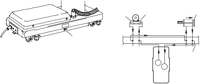
k. Flex/Reflex System
The Flex/Reflex system used on the present tables incorporates an additional mini-valve (7 total) which connects the trendelenburg and back section hydraulic systems in a series. When FLEX is activated by the pendant control, the Flex/Reflex minivalve opens the oil pressure path to the Reverse Trendelenburg piston. The return oil path from the trendelenburg piston is routed through the back section cylinder to the mini-valve return port. See
EMERGENCY BRAKE
RELEASE LEVER
Figure 1-17.
NOTE
•The emergency brake release valve must be tightened securely when not in use.
•If the emergency brake release valve has been operated, the UNLOCK button on the pendant control may have to be pressed before brakes will lock again.
If the emergency brake release valve is open or loose, two conditions could occur:
The brakes will release slowlydepending on how loose the valve is, this could take anywhere from a few minutes to several hours.
TREND |
REV TREND |
BACK UP |
|
BACK 
DOWN
PLUMBING
TERMINAL
FLEX/REFLEX
MINI-VALVE
figure 1-18.
Figure 1-18. Flex/Reflex System
Page 8

1-3. Hydraulic Adjustments
a. Fluid Level.
The fluid level should be approximately 1/2" below the filler hole or gasket surface. If additional fluid is needed, remove the filler vent cap with a phillips screwdriver and add fluid through this opening using a funnel. See figure 1-19.
NOTE
The elevation cylinder should be completely down and all the other control functions in their neutral position when checking oil level.
FILLER VENT
FILLER
CAP
RESERVOIR
OPENING
c. Pressure Relief Valve
The pressure relief valve is adjusted by turning the adjustment nut until the desired pressure is reached.
To adjust:
1. Remove the blind cap and attach a hydraulic pressure gauge to the main oil galley using a 6mm plumbing bolt. See figure 1-20.
Figure 1-19.
The type of oil that should be used is Mobil DTE #25 or equivalent. This is a very high quality hydraulic oil. The table requires approximately two quarts of oil to operate properly.
b. Bleeding The Hydraulic System
To purge the air from the hydraulic system, operate each function back and forth at least two or three times.
NOTE
Whenever a hydraulic line or component is replaced, bleed the air out of the lines using the pump pressure before making the final connection. Then operate the function until it stalls in both directions.
Figure 1-20.
2. Raise the table top until the piston reaches the end of its stroke and stalls. Observe reading on pressure gauge and turn the adjustment nut (clockwise to increase oil pressure, counterclockwise to decrease)untildesiredreadingisobtained. Pressure should be 80KG/CM† -1138 PSI.
Page 9

d. Speed Controls
The speed controls restrict the volume of oil returning back to the reservoir thereby controlling the speed of each control function.
All four-way mini-valves, have two speed controls located in the ends of each valve body. All threeway mini-valves have only one speed control.
One speed control adjusts one direction of a particular function and the opposite speed control adjusts the other direction. They are adjustable by using a small straight blade screwdriver and turning the adjustment screw clockwise to decrease the speed and counterclockwise to increase the speed. Refer to figure 1-21.
Figure 1-21.
Any control function should move in either direction at the same rate. If the rate of a certain function is too slow, open the speed control slightly and recheck. Use the second hand on a watch and time a particular function. Match that time in the opposite direction by opening or closing the speed control. Approximate operating times are as fol-
lows: |
|
Lateral Tilt |
7 seconds |
Back Up |
25 seconds |
Back Down |
15 seconds |
A pressure gauge should be used to set the speed of the back section, trendelenburg and flex control functions.
To adjust:
1.Attach the pressure gauge onto the main oil galley as shown in figure 1-21.
2.The gauge should read the following values when operating the various control functions in either direction. Turn the speed controls until desired values are obtained.
Back Section |
Up |
65KG/CM†-925PSI |
|
Dn |
65KG/CM†-925PSI |
Trendelenburg |
Up |
65KG/CM†-925PSI |
|
Dn |
65KG/CM†-925PSI |
Flex |
|
70KG/CM†-995PSI |
Reflex |
|
70KG/CM†-995PSI |
NOTE
When adjusting Flex/Reflex speed controls, set Reflex last.
Elevation - There is not a speed adjustment for raising the table. The speed control will only affect the rate of descent and it should equal the rate of elevation.
Page 10

SECTION II MECHANICAL TABLE ADJUSTMENTS 2-1. Back Section Gear Mesh Adjustment To adjust:
Loosen the cam locking nuts located inside the table side frames. Use a spanner wrench to turn the cylinder eccentric cams as required to shift either cylinder fore or aft as needed so no twisting or flexing of the back section is observed when it is stalled in the full up position. See figure 2-2.
NUT |
SPANNER |
|
WRENCH |
||
|
||
SET SCREW |
|
Figure 2-1. Eccentric Cam Adjustment
2-2. Hydraulic Cylinder Adjustment
Back & Foot / Leg Sections
The hydraulic cylinder rams that control both the back and foot / leg sections must move together so that these sections are not twisted when operated. This is accomplished by the use of eccentric cams that move the cylinder bodies fore and aft to adjust their effective stroke.
NOTE
Adjust gear mesh before adjusting eccentric cams for the back section.
a. Back Section
Position the back section all the way up until it stalls. Both sides of the back section should stop moving at the same time and should not show any signs of twisting.
Any twisting or flexing of the back section as it approaches the stalled position indicates that one of the cylinders is not reaching its fully extended position at the same time as the other. This condition would require an adjustment.
 BACK SECTION
BACK SECTION
CYLINDER
ECCENTRIC CAM
SPANNER
WRENCH
TABLE SIDE
 FRAME
FRAME
Figure 2-2. Back Section Adjustment
b. Leg Section
Position the leg section all the way up. Both sides of the leg section should stop moving at the same time and should not show any signs of twisting.
Any twisting or flexing of the leg section as it approaches the stalled position indicates that one of the cylinders is not reaching its fully extended position at the same time as the other and an adjustment is required.
To adjust:
Loosen the cam locking nuts located inside the table side frames. Use a spanner wrench to turn the cylinder eccentric cams as required to shift either cylinder fore or aft as needed so no twisting or flexing of the leg section is observed when it is stalled in the above horizontal position. Tighten locking nuts when proper adjustment is achieved. See figure 2-3.
LEG
SECTION 
TABLE SIDE FRAME
LEG CYLINDER
ECCENTRIC CAM
 SPANNER WRENCH
Figure 2-3. Leg Section Adjustment
Page 11
 Loading...