


3501 EZ Slide
Table of contents
 Loading...
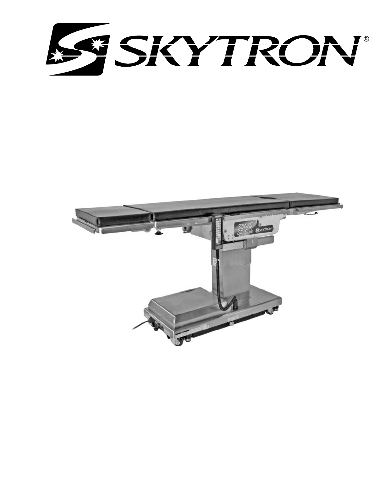
SURGICAL TABLE
3501B EZ SLIDE
OPERATORS MANUAL
1/07


Page 1
1/07
Although current at the time of publication, SKYTRON’s policy of continuous development makes this
manual subject to change without notice.
TABLE OF CONTENTS
Title Page
EQUIPMENT LABELS AND SPECIFICATIONS................................................................................... 2
3501B E-Z Slide General Purpose Surgical Table Specifications ........................................................ 3
SPECIAL USER ATTENTION ............................................................................................................... 4
SECTION I INTRODUCTION............................................................................................................... 10
1-1. General ................................................................................................................................ 10
1-2. Power Requirements ........................................................................................................... 10
1-3. Pendant Control Unit ........................................................................................................... 11
1-4. Floor Lock/Brake System .....................................................................................................11
SECTION II OPERATION .................................................................................................................... 12
2-1. Electrical Power ................................................................................................................... 12
2-2. AC 120V Operation .............................................................................................................. 12
2-3. Battery Operation ................................................................................................................. 13
2-4. Automatic Shut-Off .............................................................................................................. 13
2-5. Charging the Battery ............................................................................................................ 14
2-6. Positioning Functions ........................................................................................................... 15
a. Floor Lock/Brake system ................................................................................................. 15
b. Trendelenburg .................................................................................................................16
c. Lateral Tilt ........................................................................................................................ 16
d. Back Section ................................................................................................................... 17
e. Elevation .......................................................................................................................... 17
f. Top Slide ......................................................................................................................... 18
g. Leg Section ..................................................................................................................... 18
h. Flex Positioning ............................................................................................................... 19
i. Kidney Lift ........................................................................................................................ 19
j. Return To Level ...............................................................................................................20
2-7. Emergency Back-up controls ............................................................................................... 21
2-8. Emergency Brake Release .................................................................................................. 22
2-9. Head Section ....................................................................................................................... 22
2-10. Leg and Back Section Removal ........................................................................................... 23
SECTION III MAINTENANCE .............................................................................................................. 26
3-1. Preventive Maintenance ......................................................................................................26
3-2. Cleaning Recommendations ................................................................................................ 26
3-3. Service ................................................................................................................................. 27
Page 2
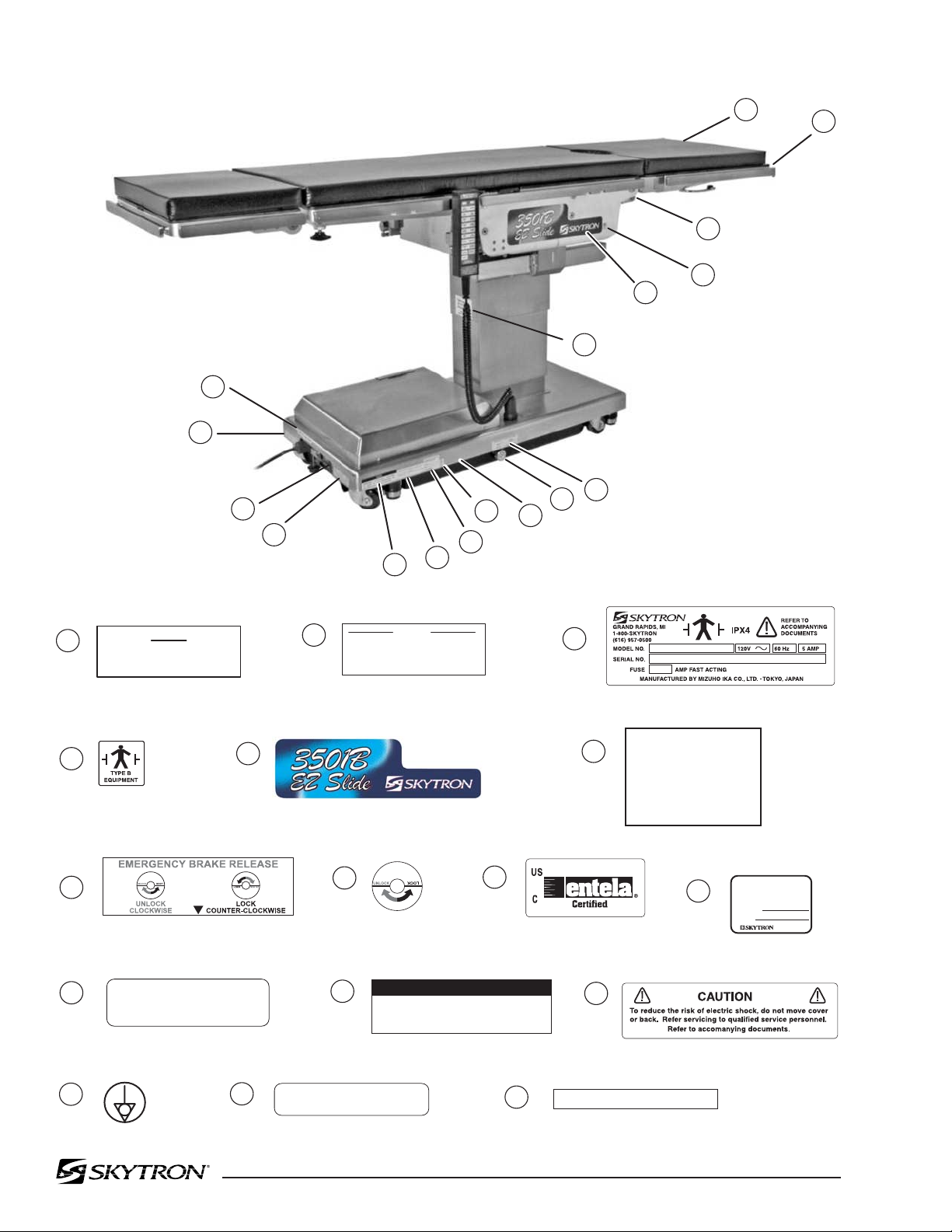
3501B EZ SLIDE EQUIPMENT LABELS
15
14
13
12
11
10
8
7
9
6
5
3
2
1
1
15
14
13
12
11
10
9
8
7
6
5
4
3
2
POSSIBL
E E
XPLOS
I
O
N
HAZARD
IF USED IN THE PRESENCE OF
FLAMMABLE ANESTHETICS.
DANGER
Grounding reliability can only be achieved when
the equipment is connected to an equivalent
receptacle marked "Hospital Only" or "Hospital Grade"
DANGER - E
XPLOS
ION
H
AZARD.
DO
NOT USE IN
T
HE
PRESENCE OF
FLA
MMAB
LE
ANAE
STHETICS
DANGER - R
IS
QUE
D'E
XPL
OSION. NE
PAS
EMPLOYER EN
PRE
SENCE
D'A
NES
TH
ES
I
QUES
INFLAMMABLES
Table Capacity:
Lift
7
00 lbs.
Articulate 6
00 lbs.
See Operators
Manual for Limitations.
THIS PRODUCT COMPLIES WITH RADIA-
TION PERFORMANCE STANDARD 21 CFR
AT THE TIME OF MANUFACTURE
Manufactured:
Model No.
WARNING
USE HEAD SECTION AS FOOT EXTENSION
ONLY - WHEN REVERSING PATIENT ON TABLE
REFER TO OPERATOR MANUAL.
DO NOT SIT ON END OF LEG SECTION(S) AS LOADS
IN EXCESS OF 140 LBS, MAY CAUSE INSTABILITY
THAT COULD CAUSE THE TABLE TO BE TIPPED OVER.
WARNING
4
4
16
16
TWIST TO LOCK OR RELEASE PLUG
D6-035-38
D3-035-60 right D3-035-61 left
D6-032-47
D6-032-46
D6-017-05
D6-065-26
D6-067-33
D6-011-34
D6-011-32
D6-031-43
D6-065-22
D6-034-21
D6-065-21
D6-067-27
L1-010-00

Page 3
3501B EZ Slide General Purpose Surgical Table Specifications
Electrical Specifications
Power requirements
Current Leakage
Power Cord
120 VAC, 60Hz, 450 Watts
Less than 100 micro amps
15 feet w/hospital grade connector (removable)
12-1/2"
18-1/4" 25" 23"
14-1/2"
19-3/4"
5-1/2"
3"
83"
TOP VIEW
90˚
60˚
14-1/2"
40-1/2"
SIDE VIEW
8-1/2"
6"
19"
21-3/4"
45" MAX
26" MIN
END VIEW
ENTELA CERTIFIED
TO UL2601-1
CAN/CSA601.1, IEC 60601-2-46

Page 4
Prior to use, all personnel that may operate this
table must be instructed in the correct opera-
tional procedures. This table is designed for
use by trained and qualified personnel for hu-
man medical purposes only.
Initial use should not begin until after the users
have been instructed by the manufacturer's
representative.
A routine instructional program must be imple-
mented by the facility for proper usage instruc-
tions for all personnel that may operate this
table.
The maximum lifting capacity of the 3501B
EZ Slide table is 700 pounds and the maximum
articulation weight capacity is 600 pounds.
When lifting or articulating large patients, pay
close attention to the patient position as well as
the positioning guidelines and limitations listed
in the operation instructions.
The extreme positioning capabilities of the 3501B
E-Z Slide Table requires special attention for pos-
sible interference points when using multiple func-
tion positioning. As with the operation of any
surgical table, a certain amount of care should be
exercised to position the patient safely. Although
the thick pads and sheets substantially protect the
patient, pinch points, located at the joints of the top
section should always be considered. BE SURE
THAT THE ARMS, HANDS AND FINGERS OF
THE PATIENT AND THOSE OF THE OPERAT-
ING ROOM PERSONNEL ARE CLEAR OF ALL
MOVING PARTS BEFORE MOVING THE TABLE.
Proper restraints should always be used for patient
safety.
Certain accessories such as the Uro-Drain Tray,
Armboards and X-Ray top can be damaged when
changing the position of the table top sections.
Always look first to see if a desired movement is
going to interfere with any accessories in use.
The operator has the ultimate responsibility of
preventing damage to the table and surrounding
equipment or possible injury to the patient or staff.
The operator must ensure proper positioning is
maintained to prevent compromising respiration,
nerve pathways or circulation.
In general, common sense will dictate when there
is a potential hazard.
The following precautions should be reviewed
by all personnel prior to operating the table.
WARNING
Indicates a possibility of personal injury.
CAUTION
Indicates a possibility of damage to
equipment.
NOTE
Indicates important facts or helpful hints.
Do not use worn or damaged accessories, they
represent an injury hazard.
Remove possible obstacles before lowering or
tilting the operating table
SPECIAL USER ATTENTION
Do not place objects on the base of the table, a
danger of damage exists during positioning.
Use caution when articulating the table top, pinch
hazards exist.

Page 5
NOTE
Activating any function button will acti-
vate the brake system. Using the TABLE
UP function to set the brakes provides
a visual assurance that the brakes are
locked without altering the table posi-
tion, except when emergency brake is
released.
WARNING
Prior to operating the table, observe
all table caution labels and review the
SPECIAL USER ATTENTION section
in the front of this manual.
WARNING
Possible explosion hazard exists if table
is used in the presence of FLAMMABLE
ANESTHETICS.
NOTE
An equalization terminal is located un-
der the main power panel. This is pro-
vided as an alternate pathway to re-
duce the risk of static shock hazards.
Always follow recommended ground-
ing procedures to ensure patient and
staff safety.
NOTE
The table will operate correctly on bat-
tery power with the power cord con-
nected to a wall outlet or disconnected.
NOTE
Battery Operation must be turned OFF
at the pendant control. It cannot be
turned OFF using the main power
switch.
NOTE
Turning the Main Power Switch ON will
change the table operation to 120 VAC
power.
NOTE
When the red light starts to blink (indi-
cating low power in battery) the table
will operate for approximately 5 con-
tinuous minutes, typically long enough
to use the table for the rest of the day.
NOTE
The charging system operates ONLY
when the table is in AC120V operation
mode.
NOTE
The table can be operated on 120VAC
power while the battery is being re-
charged.
NOTE
If the table is stored for a period greater
than 6 months, the batteries should be
removed and stored in a dry, clean con-
dition at a storage temperature of 68° F
(20° C). Batteries should be recharged
every 6 months of product storage.
SPECIAL USER ATTENTION

Page 6
WARNING
•DO NOT unlock brakes when a patient
is on the table. An uneven patient
weight load may cause instability.
•If circumstances demand table brakes
to be unlocked, the patient must be
centered and evenly distributed on the
table top (i.e. supine or prone position)
with the table lowered to its lowest
height position. The maximum patient
weight should not exceed 500 pounds.
Table top slide must be centered (indi-
cated by a red LED light on the pendant
control) prior to unlocking brakes.
Patient's head must be on the head
section. Head section must be attached
in its normal orientation to the table's
back section.
•Prior to unlocking brakes, check for
obstructions on the floor that might
prevent the table from moving smoothly
to new location. Relock the brakes im-
mediately once the final position is
reached and before commencing sur-
gery. Table brakes should remain locked
at all times if patient weight exceeds
500 pounds.
NOTE
With an evenly distributed patient weight
load, all table positioning functions will
operate smoothly and quietly with a
patient weight of up to 600 pounds
(700 pounds lift).
WARNING
To maximize patient safety, utilize
proper restraint methods during extreme
Trendelenburg positioning.
WARNING
To maximize patient safety, utilize
proper restraint methods during extreme
lateral tilt positioning.
NOTE
If the table top is slid toward the foot
end, the back section will not go below
horizontal. An audible alarm will sound.
NOTE
To prevent damage to the kidney lift, a
safety interlock prevents the back sec-
tion from going more than 45° above
horizontal if the kidney lift is not all the
way down. An audible alarm will sound.
NOTE
If the leg section is positioned more
than 45° below horizontal, the top will
not slide toward the head end. An
audible alarm will sound.
NOTE
If the back section is positioned below
horizontal, the top will not slide toward
the foot end. An audible alarm will
sound.
CAUTION
The Leg section may hit the table base
or the floor if both the leg and elevation
systems are placed in their full down
position.
SPECIAL USER ATTENTION

Page 7
CAUTION
The EMERGENCY BRAKE LOCK
switch does not activate the brake sys-
tem timer. The switch must be held
until the brakes are completely locked,
approximately 10 seconds.
NOTE
The emergency back-up control
switches will function when the table is
operating on 120VAC power, battery
power, or turned off.
WARNING
•DO NOT unlock brakes when a patient
is on the table. An uneven patient
weight load may cause instability.
•If circumstances demand table brakes
to be unlocked, the patient must be
centered and evenly distributed on the
table top (i.e. supine or prone position)
with the table lowered to its lowest
height position. The maximum patient
weight should not exceed 500 pounds.
Table top slide must be centered (indi-
cated by a green LED light on the
pendant control) prior to unlocking
brakes. Patient's head must be on the
head section. Head section must be
attached in its normal orientation to the
table's back section.
•Prior to unlocking brakes, check for
obstructions on the floor that might
prevent the table from moving smoothly
to new location. Relock the brakes im-
mediately once the final position is
reached and before commencing sur-
gery. Table brakes should remain locked
at all times if patient weight exceeds
500 pounds.
NOTE
If the top is slid toward the head end the
leg section will only go down 45°. An
audible alarm will sound.
NOTE
When FLEX button is activated and if
the top is slid toward the foot end, the
back section will not go below horizon-
tal. An audible alarm will sound.
NOTE
Return to Level will lower the kidney lift.
NOTE
To prevent damage to the kidney lift, a
safety interlock prevents the kidney lift
from going up if the back section is 45°
above horizontal. An audible alarm will
sound .
NOTE
Elevation and brake system functions
are not affected by the return to level
function.
CAUTION
The safety interlock system is not op-
erational when the emergency back-
up control switches are used.
SPECIAL USER ATTENTION

Page 8
NOTE
The Emergency Brake Release Valve
must be closed and tightened (clock-
wise) before activating any function.
•If the Emergency Brake Release Valve
has been operated, the UNLOCK button
on the pendant control will have to be
pressed before brakes will lock again.
WARNING
Consult manufacturer's instructions
when using high frequency surgical
equipment, cardiac defibrillator and car-
diac defibrillator monitors.
WARNING
When an antistatic pathway is required,
the table has to be used on an antistatic
floor.
WARNING
The antistatic properties of the table
are dependent on the use of the original
pad set which was furnished with the
table or an alternate approved replace-
ment.
SPECIAL USER ATTENTION
WARNING
Certain accessories may limit weight
capacities. Check with your SKYTRON
representative.
CAUTION
Consult SKYTRON prior to using ac-
cessories produced by other manufac-
turers.
NOTE
Always follow current AORN Journal
Guidelines to ensure proper cleaning
and disinfection procedure.
WARNING
Always follow OSHA blood-borne patho-
gens standards for protective clothing,
including gloves, masks and eye pro-
tection when cleaning the surgical table.
CAUTION
Thoroughly read and follow the
manufacturer's directions for all clean-
ing fluids. DO NOT use cleaners con-
taining phenolics.
Page 9
CAUTION
When using spray cleaners DO NOT
spray fluids directly into electrical re-
ceptacles or micro switches.
CAUTION
Before replacing pads on the table, make
sure the pads and all mating surfaces
are completely dry. Moisture trapped
between the pads and mating surfaces
may cause distortion of table tops.
WARNING
SKYTRON assumes no liability for table
performance, table damage or injury to
patient or staff when accessories not
sold or serviced by SKYTRON are
used on SKYTRON surgical tables.

Page 10
main power ON/OFF switch is located on the
electrical panel on the front edge of the table base.
See figure 1-2.
The battery charging indicator and an optional foot
control connector are also located on the electrical
panel.
Figure 1-1. 3501B EZ Slide
1-1. General
SKYTRON’s 3501B EZ Slide Surgical Table is an
electro-hydraulically operated, general purpose sur-
gical table. See figure 1-1.
The electro-hydraulic positioning functions oper-
ated by the hand-held, push button, pendant con-
trol unit are: Trendelenburg, lateral tilt, back sec-
tion, elevation, leg section, top slide, flex/reflex,
kidney lift, return to level and the floor lock/brake
system.
Manual controls are provided for head section
positioning, emergency brake release and leg sec-
tion removal.
1-2. Power Requirements
The 3501B EZ Slide Surgical Table requires a
120VAC, 60 Hz electrical power supply. The table
is equipped with a removable 15 foot long power
cord with a three prong, hospital grade plug. The
SECTION I INTRODUCTION
Figure 1-2. Electrical Panel
MAIN POWER
SWITCH
BATTERY
INDICATOR
OPTIONAL
FOOT CONTROL
CONNECTOR
POWER
CORD
REMOVABLE
LEG SECTION
SEAT
SECTION
REMOVABLE
BACK SECTION
HEAD
SECTION
SIDE
RAIL
HEAD SECTION
LOCKING KNOB
SERVICE
ACCESS COVER
POWER
CORD
MAIN POWER
SWITCH
EMERGENCY
BRAKE RELEASE
FLOOR/LOCK
BRAKE (4)
PENDANT
CONTROL
LEG SECTION
RELEASE LEVER
Page 11
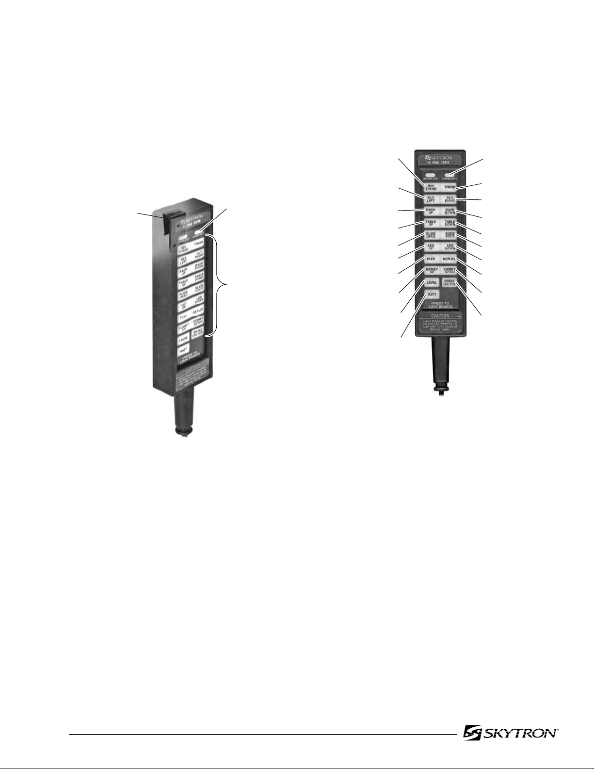
1-3. Pendant Control Unit
The hand-held pendant control unit (figure 1-3)
has a non-slip rubber cover which assures a posi-
tive grip during use. A spring clip hanger is located
on the back of the control for storage. When the
Pendant Control is not in use, it should be stored on
a convenient side or end rail.
Figure 1-3. Pendant Control Unit
The function push buttons are identified with abbre-
viated descriptions for all functions. See figure
1-4. When illuminated the Trendelenburg and
table up buttons are red, the remaining buttons are
all green.
Figure 1-4. Function Buttons
1-4. Floor Lock/Brake System
The floor lock/brake system consists of four self-
leveling, hydraulic brake cylinders which raise and
support the table base off from the casters. Press
the TABLE UP button on the pendant control to set
the table’s brakes. An electronic timer will activate
the brake system until the brakes are completely
set, approximately 8-10 seconds.
NOTE
Activating any function button will acti-
vate the brake system. Using the TABLE
UP function to set the brakes provides
a visual assurance that the brakes are
locked without altering the table posi-
tion, except when emergency brake is
released.
POWER
INDICATOR
FUNCTION
BUTTONS
SIDE RAIL
CLIP
AC120V POWER ON
INDICATOR LIGHT
(GREEN)
TABLE UP
(BRAKE LOCK)
LATERAL
TILT LEFT
BACK UP
LEG UP
SLIDE HEAD
FLEX
KIDNEY
LIFT UP
RETURN
TO LEVEL
BATTERY
LATERAL
TILT RIGHT
BACK DOWN
TABLE DOWN
LEG DOWN
SLIDE FOOT
REFLEX
KIDNEY
LIFT DOWN
BRAKE
UNLOCK
REVERSE
TRENDELENBURG
TRENDELENBURG

Page 12
2-1. Electrical Power
The 3501B table will operate on either 120 VAC or
battery power.
WARNING
Prior to operating the table, observe
all table caution labels and review the
SPECIAL USER ATTENTION section
in the front of this manual.
WARNING
Possible explosion hazard exists if table
is used in the presence of FLAMMABLE
ANESTHETICS.
NOTE
An equalization terminal is located un-
der the main power panel. This is pro-
vided as an alternate pathway to re-
duce the risk of static shock hazards.
Always follow recommended ground-
ing procedures to ensure patient and
staff safety.
2-2. AC 120V Operation
Use the following procedures to operate the table
on 120 VAC power.
a. Make sure the Power cord is securely at-
tached to the table. To install the power cord, align
the cord connector with the base connector, insert
the cord and twist clockwise to lock the cord into the
connector. See figure 2-1. Plug the cord into a
properly grounded, Hospital Grade, 120 VAC out-
let. Make sure the power cord is routed to the outlet
to prevent it from being in the way of operating
personnel.
b. Activate the POWER SWITCH located on the
electrical panel. The switch will illuminate.
SECTION II OPERATION
Figure 2-1. Electrical Panel
The pendant control buttons and the green AC
120V, POWER indicator light located in the upper
right corner of the pendant control will illuminate.
See figure 2-2.
MAIN POWER
SWITCH
TWIST TO
LOCK
BATTERY
INDICATOR
POWER
CORD
EQUALIZATION
GROUNDING TERMINAL
OPTIONAL
FOOT CONTROL
CONNECTOR
Figure 2-2. Pendant Control
c. The table is now ready for 120VAC operation.
AC120V POWER ON
INDICATOR LIGHT
(GREEN)

Page 13
2-3. Battery Operation
a. Make sure the Main Power Switch indicator
light, on the electrical panel, is OFF. See figure 2-
2. If the indicator light is ON, turn AC120V opera-
tion OFF with the main power switch.
NOTE
The table will operate correctly on bat-
tery power with the power cord con-
nected to a wall outlet or disconnected.
b. Press the BATT button on the hand-held
pendant control. The pendant control buttons, the
red BATTERY indicator light, located in the upper
right corner of the pendant control and the Battery
Indicator on the electrical panel will illuminate.
c. The table is now ready for BATTERY opera-
tion.
d. To extend the battery charge life, turn the
BATTERY power OFF with the pendant control
when the table is not going to be used.
NOTE
Battery Operation must be turned OFF
at the pendant control. It cannot be
turned OFF using the main power
switch.
2-4. Automatic Shut-Off
a. To prevent unnecessary discharge of the
battery, a timer is built into the battery circuit. This
timer will automatically shut the battery power OFF
after 1½ hours of table inactivity.
b. To turn the table ON again, press the BATT
button on the pendant control, the pendant control
buttons and the red indicator light will illuminate.
NOTE
Turning the Main Power Switch ON will
change the table operation to 120 VAC
power.

Page 14
b. If the battery needs to be charged when
operating the table on battery power, the red indi-
cator light on the pendant control will begin to blink.
NOTE
When the red light starts to blink (indi-
cating low power in battery) the table
will operate for approximately 5 con-
tinuous minutes, typically long enough
to use the table for the rest of the day.
NOTE
The charging system operates ONLY
when the table is in AC120V operation
mode.
c. To recharge the battery, make sure the power
cord is connected, plugged into a 120VAC wall
outlet and the main POWER SWITCH - ON.
NOTE
The table can be operated on 120VAC
power while the battery is being re-
charged.
d. A full battery charge will last approximately 2
weeks under normal operating conditions. How-
ever, it is recommended to charge the batteries at
the end of each week to establish a normal routine
protocol. Lead acid batteries last longer if they are
not permitted to fully discharge. The table features
(2) 12 volt, sealed, lead acid batteries which re-
quire no manual maintenance. Lead acid gel bat-
teries, under a proper charging program, feature
an approximate normal life of 4 years.
NOTE
If the table is stored for a period greater
than 6 months, the batteries should be
removed and stored in a dry, clean con-
dition at a storage temperature of 68° F
(20° C). Batteries should be recharged
every 6 months of product storage.
2-5. Charging the Battery
Batteries should be charged:
• When the table is placed into initial
service
• As indicated by Battery Indicator
• Every week under normal service
conditions
a. Battery Indicator The Battery Indicator
consists of ten lighted bars, 3 red, 4 yellow and 3
green. See figure 2-3. Each bar represents a
percentage of the battery charge condition. When
all ten bars are illuminated, the batteries are fully
charged. The following list shows the battery
charge level as indicated by the lighted bars;
3 green 100% -Fully charged
2 green 89%
1 green 78%
4 yellow 67%
3 yellow 56%
2 yellow 45% -Needs Charging (BATT
indicator on pendant will flash)
1 yellow 34% -Needs Charging
3 red 23% -Needs Charging
(poor performance)
2 red 12% -Needs Charging
(intermittent performance)
1 red 1% -Needs Charging
(inoperable)
During charging, the bars will light in sequence to
the respective charge level, turn off and light in
sequence again.
Figure 2-3. Battery Indicator
BATTERY
INDICATOR

Page 15
Figure 2-4. Pendant Control Function Buttons
a. Floor Lock/Brake System. To activate the
brakes without affecting table positioning, press
the TABLE UP button. See figure 2-5. The
elevation cylinder will not function until the brakes
are completely extended.
2-6. Positioning Functions
The hand-held pendant control (figure 2-4) acti-
vates the following table functions:
Figure 2-5. Brake System Activation
Press the BRAKE UNLOCK button on the pendant
control to release the four self-leveling brake feet in
order to move the table. See figure 2-5. The brake
delay circuit automatically retracts the brake sys-
tem. It takes approximately 7-8 seconds to totally
release the system.
WARNING
•DO NOT unlock brakes when a patient
is on the table. An uneven patient
weight load may cause instability.
•If circumstances demand table brakes
to be unlocked, the patient must be
centered and evenly distributed on the
table top (i.e. supine or prone position)
with the table lowered to its lowest
height position. The maximum patient
weight should not exceed 500 pounds.
Table top slide must be centered (indi-
cated by a red LED light on the pendant
control) prior to unlocking brakes.
Patient's head must be on the head
section. Head section must be attached
in its normal orientation to the table's
back section.
•Prior to unlocking brakes, check for
obstructions on the floor that might
prevent the table from moving smoothly
to new location. Relock the brakes im-
mediately once the final position is
reached and before commencing sur-
gery. Brake should remain locked at all
times if patient weight exceeds 500
pounds.
NOTE
With an evenly distributed patient weight
load, all table positioning functions will
operate smoothly and quietly with a
patient weight of up to 600 pounds
(700 pounds lift).
AC120V POWER ON
INDICATOR LIGHT
(GREEN)
TABLE UP
(BRAKE LOCK)
LATERAL
TILT LEFT
BACK UP
LEG UP
SLIDE HEAD
FLEX
KIDNEY
LIFT UP
RETURN
TO LEVEL
BATTERY
LATERAL
TILT RIGHT
BACK DOWN
TABLE DOWN
LEG DOWN
SLIDE FOOT
REFLEX
KIDNEY
LIFT DOWN
BRAKE
UNLOCK
REVERSE
TRENDELENBURG
TRENDELENBURG
TABLE UP
(BRAKE LOCK)
BRAKE
UNLOCK

Page 16
b. Trendelenburg. To place the table in a
Trendelenburg (head down) position, press the
TREND button (figure 2-6). Trendelenburg posi-
tioning of up to 25° may be obtained. To place the
table in a reverse Trendelenburg (head up) posi-
tion, press the REV TREND button. Reverse
Trendelenburg positioning of up to 20° may be
obtained.
WARNING
To maximize patient safety, utilize
proper restraint methods during extreme
Trendelenburg positioning.
Figure 2-6. Trendelenburg Positioning
c. Lateral Tilt. To achieve lateral tilt right (as
viewed from the head end of the table), press the
TILT RIGHT button (figure 2-7). Tilt of up to 20° may
be obtained. To achieve lateral tilt left, press the TILT
LEFT button. Tilt of up to 20° may be obtained.
WARNING
To maximize patient safety, utilize
proper restraint methods during extreme
lateral tilt positioning.
Figure 2-7. Lateral Tilt Positioning
25˚
20˚
REVERSE
TRENDELENBURG
TRENDELENBURG
20˚ 20˚
LATERAL
TILT LEFT
LATERAL
TILT RIGHT

Page 17
d. Back Section. To raise the back section,
press the BACK UP button (figure 2-8). The back
section will raise up to 90° above horizontal. To
lower the back section, press the BACK DOWN
button. The back section will go down to 40° below
horizontal.
NOTE
If the table top is slid toward the foot
end, the back section will not go below
horizontal. An audible alarm will sound.
NOTE
To prevent damage to the kidney lift, a
safety interlock prevents the back sec-
tion from going more than 45° above
horizontal if the kidney lift is not all the
way down. An audible alarm will sound.
Figure 2-8. Back Section Positioning
e. Elevation. To raise table top, press the
TABLE UP button (figure 2-9). The table will lift a
patient weight of 700 pounds up to a maximum
height of 45". To lower the table top, press the
TABLE DOWN button. The table top will go down
to a minimum height of 26" (minus pad).
Figure 2-9. Elevation Function
90˚
40˚
BACK UP
BACK DOWN
45"
TABLE
UP
TABLE
DOWN
26"
Page 18
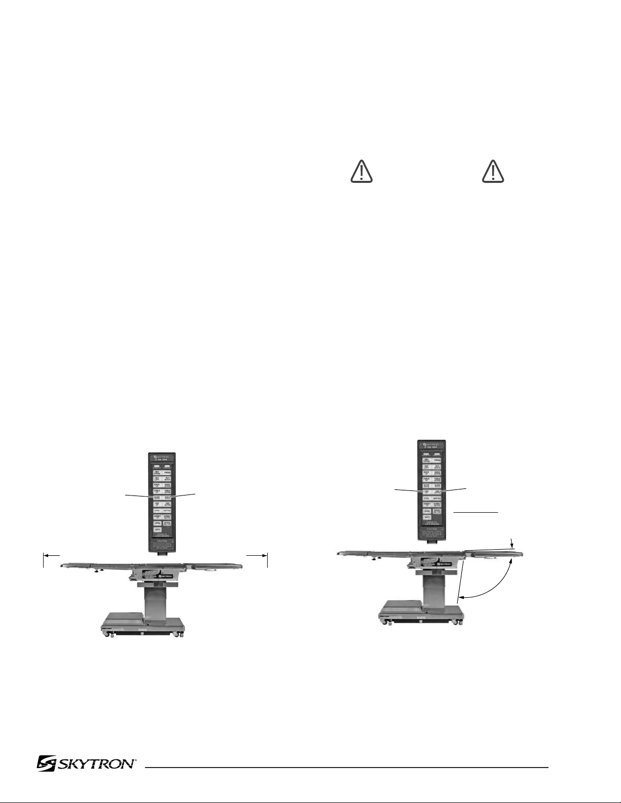
f. Top Slide. To move the table top toward the
head end, press the SLIDE HEAD button. From
center position, the top will slide up to 7-1/2". See
figure 2-10.
NOTE
If the leg section is positioned more
than 45° below horizontal, the top will
not slide toward the head end. An
audible alarm will sound.
To move the table top toward the foot end, press
the SLIDE FOOT button. From center position, the
top will slide up to 13-1/2". Slide function will stop
and SLIDE/CTR Indicator will illuminate when table
is centered.
NOTE
If the back section is positioned below
horizontal, the top will not slide toward
the foot end. An audible alarm will
sound.
g. Leg Section. To lower the leg section, press
the LEG DOWN button (figure 2-11). The leg
section will go down to 98° below horizontal. To
raise the leg section, press the LEG UP button.
The leg section will go up to level.
CAUTION
The Leg section may hit the table base
or the floor if both the leg and elevation
systems are placed in their full down
position.
NOTE
If the top is slid toward the head end, the
leg section will only go down 45°. An
audible alarm will sound.
Figure 2-11. Leg Section Positioning
Figure 2-10. Top Slide
98˚
2˚
LEG UP
LEG DOWN
7-1/2"
SLIDE HEAD
SLIDE FOOT
13-1/2"

Page 19
Figure 2-13. Kidney Lift Positioning
j. Return To Level. To return the table top to a
level position, press the LEVEL button (figure 2-14).
NOTE
Elevation and brake system functions
are not affected by the return to level
function.
h. Flex Positioning. To place the table top in
a flex position from horizontal, press the FLEX
button (figure 2-12). To return the table top to a
horizontal position or into a reflex position, press
the REFLEX button.
NOTE
When FLEX button is activated and if
the top is slid toward the foot end, the
back section will not go below horizon-
tal. An audible alarm will sound.
Figure 2-12. Flex/Reflex Positioning
i. Kidney Lift. To raise the built-in kidney lift,
press the KIDNEY UP button (figure 2-13). Up to
5-1/2" of lift can be achieved. Press the KIDNEY
DOWN button to lower the kidney lift.
NOTE
Return to Level will lower the kidney lift.
NOTE
To prevent damage to the kidney lift, a
safety interlock prevents the kidney lift
from going up if the back section is 45°
above horizontal. An audible alarm will
sound .
Figure 2-14. Return To Level
FLEX
REFLEX
5-1/2"
KIDNEY UP
KIDNEY DOWN
RETURN
TO LEVEL

Page 20
Figure 2-16. Emergency Back-Up Controls
CAUTION
The EMERGENCY BRAKE LOCK
switch does not activate the brake sys-
tem timer. The switch must be held
until the brakes are completely locked,
approximately 10 seconds.
NOTE
The emergency back-up control
switches will function when the table is
operating on 120VAC power, battery
power, or turned off.
c. Switches are provided for Trendelenburg,
lateral tilt, back section, elevation, leg section,
kidney down and brake lock. These switches are
spring-loaded so they return to the neutral or
center position when released.
2-7. Emergency Back-up Controls
a. The emergency back-up control switches are
located under the access door on the service
access cover in the table base. See figure 2-15.
Figure 2-15. Emergency Controls Location
b. In the event of either a power failure or a
problem with the hand-held pendant control, the
table can be operated using the emergency back-
up switches. Simply push the desired emergency
switch in the appropriate direction to operate the
table functions. See figure 2-16.
CAUTION
The safety interlock system is not op-
erational when the emergency back-
up control switches are used.
FUNCTION CONTROL
ACCESS DOOR
REV
TREND
TILT
RIGHT
BACK
UP
TABLE
UP
LEG
UP
BRAKE
LOCK
TREND TILT
LEFT
BACK
DOWN
TABLE
DOWN
LEG
DOWN
KIDNEY
DOWN

Page 21
2-8. Emergency Brake Release.
In case of a power failure or an electrical problem
within the table, the emergency brake release
system can be used to move the table. The control
knob for this function is located on the side of the
table base and is identified by an EMERGENCY
BRAKE RELEASE label. Turn the knob counter-
clockwise to release the brakes. See figure 2-17.
WARNING
•DO NOT unlock brakes when a patient
is on the table. An uneven patient
weight load may cause instability.
•If circumstances demand table brakes
to be unlocked, the patient must be
centered and evenly distributed on the
table top (i.e. supine or prone position)
with the table lowered to its lowest
height position. The maximum patient
weight should not exceed 500 pounds.
Table top slide must be centered (indi-
cated by a green LED light on the
pendant control) prior to unlocking
brakes. Patient's head must be on the
head section. Head section must be
attached in its normal orientation to the
table's back section.
•Prior to unlocking brakes, check for
obstructions on the floor that might
prevent the table from moving smoothly
to new location. Relock the brakes im-
mediately once the final position is
reached and before commencing sur-
gery. Table brakes should remain locked
at all times if patient weight exceeds
500 pounds.
Figure 2-17. Emergency Brake Release
NOTE
The Emergency Brake Release Valve
must be closed and tightened (clock-
wise) before activating any function.
•If the Emergency Brake Release Valve
has been operated, the UNLOCK button
on the pendant control will have to be
pressed before brakes will lock again.
SERVICE ACCESS
COVER
POWER
CORD
EMERGENCY
BRAKE RELEASE
BRAKE (4)

Page 22
Figure 2-19. Repositioning Head Section
(for use as a Foot Extension)
2-9. Head Section
a. A quick release positioning bar located under
and to the front of the head section (figure 2-18) is
used to raise or lower the head section. Pull the
release bar toward the head end to allow the
section to pivot up or down. Positioning from 60°
above horizontal to 90° below horizontal in 15°
increments is available. Release the bar to lock the
head section in position.
2-10. Leg Section Removal.
NOTE
The leg section with the x-ray top + pad
attached weighs 31 lbs. It is recom-
mended that the x-ray top and pad be
removed before detaching the leg section.
a. To remove the leg section, position the table
top height to elbow height, and simultaneously
depress both release levers and pull the leg section
out. See figure 2-20. Press the LEG-DOWN
button on the pendant control to position the leg
section attachment pins down and out of the way.
Figure 2-18. Head Section Adjustment
b. By loosening two locking knobs beneath the
back section, an additional 2" of longitudinal ad-
justment can be achieved. If desired, the head
section may be removed by loosening the locking
knobs and pulling it straight out of the back section.
3501B EZ Slide Table has the capability of attach-
ing the head section to the leg section
for use as a
foot extension ONLY. Do Not reverse the patient
on the table without first consulting with SKYTRON.
Two locking knobs are located on the inside of the
leg section for securing the head section. See
figure 2-19.
Figure 2-20. Leg Section Release Levers
b. To Install Leg Section, press and hold the
LEG-UP button until the leg section attachment
pins completely stop before reinstalling the leg
section to the table. Pull out on the leg section after
installation to make sure the release levers are
completely locked.
HEAD SECTION
RELEASE BAR
HEAD
SECTION
FOOT/LEG
SECTION
LOCKING
KNOB
LOCKING
KNOB
(RECESSED)
FOOT/LEG SECTION
LOCKING
LEVERS

Page 23
2-11. Positioning
The use of certain optional accessories available
from SKYTRON further extend the positioning
capabilities of the 3501B E-Z Slide Table. Refer to
the following "Positioning Guidelines" or contact
your SKYTRON representative for further details.
WARNING
Certain accessories may limit weight
capacities. Check with your SKYTRON
representative.
CAUTION
Consult SKYTRON prior to using ac-
cessories produced by other manufac-
turers.
WARNING
Consult manufacturer's instructions
when using high frequency surgical
equipment, cardiac defibrillator and car-
diac defibrillator monitors.
WARNING
When an antistatic pathway is required,
the table has to be used on an antistatic
floor.
WARNING
The antistatic properties of the table
are dependent on the use of the original
pad set which was furnished with the
table or an alternate approved replace-
ment.

Page 24
3-2. Cleaning Recommendations
NOTE
Always follow current AORN Journal
Guidelines to ensure proper cleaning
and disinfection procedure.
The following procedures should be followed when
cleaning the surgical table between cases.
Place table top in level position prior to starting
cleaning procedure.
WARNING
Always follow OSHA blood-borne patho-
gens standards for protective clothing,
including gloves, masks and eye pro-
tection when cleaning the surgical table.
Remove major contaminants from the table with
disposable materials following appropriate biohaz-
ard waste disposal procedures.
Remove all table pads and place them on a flat
surface for cleaning.
CAUTION
Thoroughly read and follow the
manufacturer's directions for all clean-
ing fluids. DO NOT use cleaners con-
taining phenolics.
Apply cleaning fluid liberally to top and sides of
each pad and wipe with a clean lint-free cloth.
Using a clean, damp, lint-free cloth, wipe the pads
to remove the cleaning fluid.
Using a clean, dry, lint-free cloth, wipe the pads to
remove all moisture.
3-1. Preventive Maintenance
The following preventive maintenance checks and
services are recommended to ensure the service-
ability and proper operation of your SKYTRON
Surgical Table, and should only be performed by
qualified SKYTRON trained personnel.
a. During normal cleaning, a general visual
examination should be made checking for leaks,
loose bolts or parts, and cracked, chipped, or
missing paint. Any necessary repairs should be
made.
b. Semi-annually the following checks and ser-
vices should be performed:
1. Check all hydraulic fittings, mini-valves and
slave cylinders for proper operation and
any signs of leaks.
2. Check the hydraulic speed controls and
adjust if necessary.
3. Pressure check (with a gauge) the pres-
sure relief valve.
4. Check all mechanical adjustments and ad-
just as necessary.
5. Check hydraulic fluid level.
6. Lubricate the slider assembly.
7. Check function of foot leg release levers,
lubricate as necessary.
SECTION III MAINTENANCE

Page 25
Repeat the steps to clean the bottom of the each
pad.
CAUTION
When using spray cleaners DO NOT
spray fluids directly into electrical re-
ceptacles or micro switches.
Repeat cleaning procedure for all table surfaces
including the top, sides, elevation column, base
and all accessories.
CAUTION
Before replacing pads on the table, make
sure the pads and all mating surfaces
are completely dry. Moisture trapped
between the pads and mating surfaces
may cause distortion of table tops.
WARNING
SKYTRON assumes no liability for table
performance, table damage or injury to
patient or staff when accessories not
sold or serviced by SKYTRON are
used on SKYTRON surgical tables.
When the cleaning procedure is complete, replace
all pads and accessories as applicable.
Remove pendant control from table side rail and
apply cleaning solution to the pendant control and
cord.
Use a clean cloth dampened with water to remove
cleaning solution.
Use another clean damp cloth to remove any
remaining residue.
Install pendant control on side rail for storage when
cleaning procedure is complete.
3-3. Service
Table maintenance can be performed by trained
maintenance personnel using SKYTRON autho-
rized replacement parts and service techniques.
Service instructions and parts are available from
SKYTRON.
Preventive Maintenance contracts are available
through your local SKYTRON representative.
To obtain service instructions, replacement parts,
factory service or preventive maintenance con-
tracts, contact the SKYTRON representative listed
below.
Or contact:
SKYTRON
5000 36th Street S.E.
Grand Rapids, MI 49512
1-800-SKYTRON (1-800-759-8766)
Fax. 1-616-957-5053

5000 36th Street S.E., Grand Rapids, MI 49512
1-800-SKYTRON or 1-616-957-0500 • FAX 1-616-957-5053

SURGICAL TABLE
3501B EZ SLIDE
PARTS CATALOG
1/07
 Loading...