


L
LFS SERIES
Page 27
REV 7-05
OWNERS MANUA


Page 1
TABLE OF CONTENTS
TITLE PAGE
EQUIPMENT LABELS AND SPECIFICATIONS ................................................................................. 2
Special User Attention.............................................................................................................................. 3
Introduction .............................................................................................................................................. 4
Basic Lighthead Operation....................................................................................................................... 6
Lighthead Positioning ............................................................................................................................... 8
Illumination Technique............................................................................................................................ 10
Maintenance........................................................................................................................................... 14
Repair Parts ........................................................................................................................................... 18
Hub and Radial Arm Assembly ........................................................................................................ 18
Flatscreen Bracket Assembly.......................................................................................................... 20
Height Adjustable Arm Assembly..................................................................................................... 22
REV 7/05
Although current at the time of publication, SKYTRON'S policy of continuous development makes this
manual subject to change without notice.

Page 2
EQUIPMENT LABELS AND SPECIFICATIONS
ATTENTION, CONSULT MANUAL FOR FURTHER INSTRUCTIONS.
INDICATES SPECIAL USER ATTENTION.
AC VOLTAGE
3A
5A
TYPE B
EQUIPMENT
FUSE TYPE 3 AMP, SLOW BLOW TYPE
FUSE TYPE 5 AMP, SLOW BLOW TYPE
CLASS I DEFIBRILLATION PROOF, TYPE B EQUIPMENT- IPX4 RATED.
INTERNALLY POWERED EQUIPMENT
FOR DRY LOCATIONS
UNIT TO BE USED ONLY IN SPECIFIED ENVIRONMENTAL CONDITIONS
TEMPERATURE: 15 - 30 C (60 -85 F)
HUMIDITY: 30% - 60% RELATIVE HUMIDITY, NON CONDENSING
ENTELA CERTIFIED
TO UL2601-1
CAN/CSA601.1, IEC 60601-2-46
The lighthead Data Label contains the lighthead
model number, bulb type, fuse type, electrical specifications
and product serial number.
FUSE
TYPE
- GRAND RAPIDS, MI
ELECTRIC RATING
INPUT
BULBS TYPE
SAFETY FUSE
SERIAL NO.
DAI-ICHI SHOMEI CO., LTD. TOKYO, JAPAN
120V
H24501
CAT. NO.
60Hz
24V 50W
IPXO CLASS 1
TYPE B
MODEL
(CAT. NO.)
SERIAL NO.

SPECIAL USER ATTENTION
Page 3
To help assure the highest degree of operating
safety for user and patient, SKYTRON has provided precautionary instructions throughout this
manual.
As with the operation of any surgical light, all
hospital personnel should be aware that a certain
amount of care must be exercised to maintain
patient safety and to keep your SKYTRON light
fixture performing at peak efficiency.
The following is a summary of the important precautionary instructions:
WARNING
Indicates a possibility of personal injury.
CAUTION
Indicates a possibility of damage to
equipment.
NOTE
Indicates important facts or helpful hints.
NOTE
To prolong bulb life, the sof-start bulb
protection circuit will cause a slight delay
before the bubs will illuminate.
NOTE
Always make sure that the handle is
properly engaged. Failure to perform
this procedure could result in the
inadvertent release of the center focus
handle.
NOTE
SKYTRON products are guaranteed
for proper performance with the use of
genuine SKYTRON CENTER FOCUS
HANDLES. After market competitive
handles and other disposable handles
will have varying results that could
ultimately affect the proper performance
and secure engagement of the center
focus handle. Such applications are at
the discretion of the user to ensure
patient safety.
CAUTION
To ensure product performance,
product longevity, and patient/staff
safety, always take caution to avoid
impact to the fixture when positioning.
NOTE
For LFSLFS position the second arm in
the same way on the opposite side of
the table.
NOTE
All repairs should be made using only
authorized SKYTRON replacement
parts.
WARNING
Be sure the power is turned "OFF" and
the bulbs have cooled before changing.
WARNING
DO NOT attempt to remove a bulb by
pulling on the glass surface or end cap.
This may cause the bulb to break off in
your hand.
NOTE
Halogen bulbs are sensitive to body
oils. DO NOT handle glass surface of
bulb as body oil from fingers can create
a "hot spot" and may cause the bulb to
burn out prematurely.
NOTE
To extend the life of the bulb reflector
surface, it should not be included in
normal cleaning. It should be cleaned
only if absolutely necessary. Clean
gently with a clean, damp, soft cloth and
a mild soap solution. NO abrasives.
NOTE
The system can support and balance a
monitor weight up to 22 lbs. Exceeding
the weight will result in poor balance and
performance.
NOTE
Refer to applicable light model
maintenance and parts manuals for light
fixture components.

Page 4
540˚
340˚
CEILING
COVER
BALANCE
MECHANISM
INTRODUCTION
345˚
360˚
PITCH
360˚
ROLL
360˚
VERTICAL
SUPPORT
TUBE
540˚
340˚
VERTICAL
SUPPORT
TUBE
110˚
VERTICAL
TRAVEL
BALANCE
MECHANISM
Figure 1. Light Fixture Rotation Capabilities
The Stellar LFS series combines flatscreen monitor mounting with a surgical lighting system from a
single ceiling mount.
The LFS model allows a single flatscreen monitor
mount to be combined with up to 3 separate
lightheads. The LFSLFS model combines 2
flatscreen monitor mounts with up to 2 separate
lightheads.
The LFS radial arm assembly allows up to 90" of
reach for the flatscreen monitor with 345° of rotation
capability at the ceiling mount. Vertical travel of up
to 45.5" is provided.
360˚
360˚
PITCH
360˚
ROLL
360˚
The lighthead models available for use with the
LFS system include ST19WC, ST23, ST23TV,
ST29 and ST29TV. The ST19WC model is fixed
focus, the remaining models are all focusable.

Page 5
The Stellar series surgical lighting system from
SKYTRON features fully adjustable positioning
and focus control for its cool, color-corrected,
multiple bulb, light source. Combinations of vertical
positioning and multiple rotational capabilities allow
the single, dual or triple lighthead models virtually
limitless positioning.
The fixtures are single point ceiling mounted with a
continuous 360 degree rotation capability at the
ceiling mount end of the radial support arm. See
figure 1. The balance mechanism which is attached to the radial arm by a vertical support tube,
provides the lighthead an additional continuous 360
degree rotation point. The balance mechanism is
an enclosed spring tension system. This allows
vertical movement of the lighthead while maintaining the lighthead position without drifting. The yoke
provides additional 360 degree rotation points for
lighthead pitch and roll.
The Stellar fixtures have a lighthead vertical travel
capability of 110°.
The adjustable focus mechanism which optimizes
the light output by superimposing all the light beams
into a single spot can be operated by non-sterile
personnel using the lighthead mounted focus knob.
All lightheads also have a removable, sterilizable,
focus/positioning handle. This allows all final positioning and focus adjustments or changes to be
precisely done by the surgeon. See figure 2.
NON-STERILE
SIDE FOCUS KNOB
STERILIZABLE
FOCUS/POSITIONING
HANDLE
Figure 2. Focus Adjustments
Page 6
FOCUS
KNOB
BASIC LIGHTHEAD OPERATION
RADIAL ARM
ASSEMBLY
VERTICAL
SUPPORT
TUBE
STERILIZABLE
FOCUS/POSITIONING
HANDLE
Figure 3. Dual Lighthead Fixture
Use the following instructions to operate the light
fixture:
1. Position the lightheads as required by grasping the lighthead positioning handles and moving
the lighthead to the desired position. See figure 3.
BALANCE
MECHANISM
FOCUS
KNOB
STERILIZABLE
FOCUS/POSITIONING
HANDLE
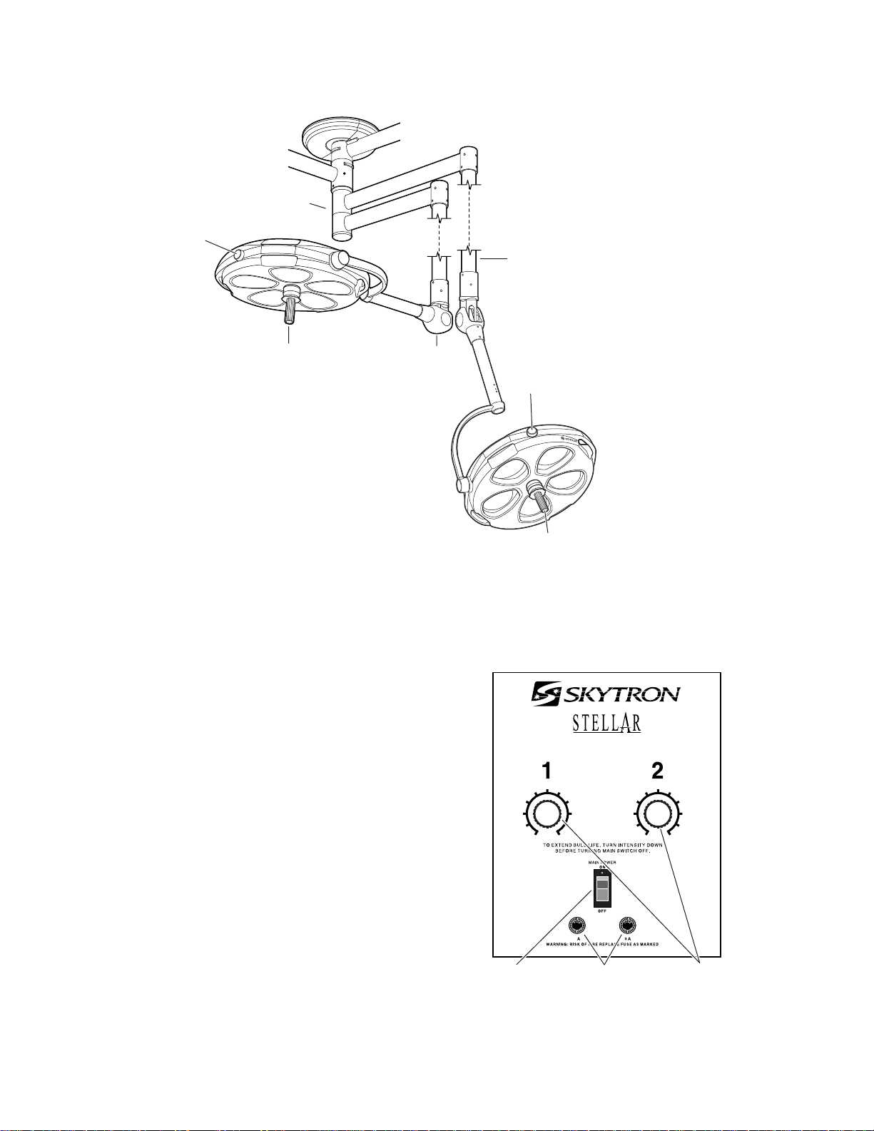
2. Turn the light fixture main power switch "ON"
at the wall mounted control box and select the
desired intensity for each lighthead as required.
See figure 4. The mid-range position will provide
adequate illumination for most procedures. Full
intensity will usually only be required for extreme
deep cavity cases.
NOTE
To prolong bulb life, the sof-start bulb
protection circuit will cause a slight delay
before the bulbs will illuminate.
5
6
4
37
28
19
010
MAIN
POWER
SWITCH
5
SAFETY
FUSES
5
6
4
37
28
19
010
INTENSITY
CONTROL
KNOBS
Figure 4. Wall Mounted Control Box

Page 7
3. When the surgeon is ready to use the light,
install the sterilized center focus/positioning handle
using the following procedure. See figure 5. Be
sure handle is properly secured before using the
lighthead. Possible injury to patient or staff could
result if a handle is not installed properly.
a. Insert the handle into the lighthead at-
tachment ring.
NOTE
Always make sure that the handle is
properly engaged. Failure to perform
this procedure could result in the
inadvertent release of the center focus
handle.
b. Push the handle in, turn it right and left, and pull
the handle out to be certain that it is locked (PUSHTWIST-PULL). A distinct click can be heard when
the handle is properly engaged.
c. To remove the handle, push the release
button and pull the handle out.
4. Adjust the focus by moving either the nonsterile focus knob or the (sterilized) center focus
handle until all of the light beams converge on the
surgical site forming a single bright spot of light.
5. For low angle lighting approach, the lighthead
will move 90° below horizontal. Pull the lighthead
down by the positioning handles or the (sterile)
positioning/focus handle.
In the presence of flammable anesthetics, DO
NOT allow the lighthead to travel below 60 inches
from the floor.
6. When the light is no longer required, return
the lighthead to its full up position. Decrease the
intensity at the wall control, and turn the main power
switch "OFF".
NOTE
SKYTRON products are guaranteed
for proper performance with the use of
genuine SKYTRON CENTER FOCUS
HANDLES. After market competitive
handles and other disposable handles
will have varying results that could
ultimately affect the proper performance
and secure engagement of the center
focus handle. Such applications are at
the discretion of the user to ensure
patient safety.
STERILIZABLE
HANDLE
HANDLE
RELEASE
BUTTON
Figure 5. Center Focus/Positioning Handle
Installation

Page 8
LIGHTHEAD POSITIONING
General
To obtain the maximum benefit from your
SKYTRON surgical lighting system, the following
suggestions are offered as a guide for lighthead
positioning. Personnel who are trained in proper
lighting techniques can plan and set up the lighting
arrangements prior to the arrival of the patient.
Factors which should be considered when
prepositioning surgical lights are:
-Specific procedure to be done
-Patient position during procedure
-Position of surgical team
-Location of instrument trays or tables
-Location of IV stands
-X-ray equipment and personnel
-Anesthesia equipment and personnel
-Angulation and size of surgical cavity
CAUTION
To ensure product performance,
product longevity, and patient/staff
safety, always take caution to avoid
impact to the fixture when positioning.
The lightheads can be most effectively positioned
by using the following procedures:
1. Grasp the positioning handles on the lighthead
and pull the lighthead down to shoulder height.
Keep the lighthead at approximately a 45° angle to
easily position the support yoke. See figure 6.
Surgical Table Placement
For most procedures the surgical table should be
located with its center point directly under the light
fixture’s ceiling mount.
Pre-Positioning The Lighthead
Surgical light positioning requirements change not
only from procedure to procedure, they also change
from surgeon to surgeon. Final light positioning
and adjustment will be directed or done directly by
the surgeon. The objective of prepositioning is to
require a minimum of final adjustments after arrival
of the patient. The non-sterile focus control should
be located where it can be reached by non-sterile
personnel and the sterile positioning/focus handle
where they can be reached by the surgeon. Use
extreme care when prepositioning lightheads.
Bumping lightheads into one another, into walls, or
other equipment may alter bulb alignment which
affects proper focus adjustment.
SUPPORT
YOKE
POSITIONING
HANDLE
Figure 6.
2. Using the positioning handles, rotate the
lighthead around the vertical support until the
lighthead is at an approximate 90° angle to the
radial arm. See figure 7.
RADIAL ARM
90˚
Figure 7.

Flatscreen Monitor Positioning
Page 9
3. Place the radial arm in the desired position by
pushing or pulling the lighthead by the positioning
handles as you walk around the surgical table.
4. Refer to figure 8 to approximate the desired
radial arm position for locating the lighthead over
the patient.
ABDOMINAL
PELVIC
ORTHO
OB/GYN
90˚
HIP
45˚
180˚ 180˚
DOCTOR SIDE OF TABLE
CHEST
45˚
NEURO
EENT
The upper radial arm of the flatscreen monitor
mount should be pre-positioned on the opposite
side of the table from the surgeon at approximately
90° from the table center line. See figure 9.
Figure 8. Main Lighthead Radial Arm
Positioning
5. With the radial arm in proper position, rotate
the lighthead to the desired position and install the
sterile positioning/focus handle. Refer to sterile
handle installation procedure.
6. Grasp the positioning handles, place the
lighthead at an angle and move the lighthead to its
full up position.
Figure 9.
The lower arm should be positioned under the
upper arm. In this position the monitor can be easily
moved up or down the full length of the table without
interfering with the lightheads. The monitor can be
pushed up out of the way until it is needed.
Two sterilizable handles are provided for final monitor positioning or for changes required during the
procedure. Prior to the start of the procedure the
sterilizable handles can be installed. Insert the
sterile handles into the receptacle and turn clockwise until tight.
NOTE
For LFSLFS position the second arm in
the same way on the opposite side of
the table.

Page 10
ILLUMINATION TECHNIQUE
Maximum illumination, shadow reduction, and possible obstruction by the surgeon or surgical staff
are also major concerns for lighthead positioning.
The following examples are offered as a basic
guide for lighthead placement for large diameter/
satellite, dual lighthead, or triple lighthead fixtures.
Large Diameter/Satellite Lighthead
Positioning
The large diameter lighthead should be pre-positioned over the surgical site. The satellite can be
used on either side of the surgeon for augmentation
and shadow control.
The large lighthead should be positioned perpendicular to the bottom of the surgical cavity.
Head
To illuminate the head area, position the large
diameter lighthead radial arm parallel to the table
centerline. See figure 10. Position the lighthead
behind the surgeon. Tilt the lighthead to the desired
position using pitch axis movement. This will allow
the multiple light sources of the lighthead to pass
around the head and shoulders of the surgeon and
at the same time permit adequate head clearance
for the surgeon.
Tilt the lighthead to position the focus control knob
where it can be easily reached by non-sterile
personnel.
Position the satellite to the left or right according to
surgeon preference. This allows a second light
source to come from another angle which will help
eliminate obstructions or shadows.
Torso Area
For most chest and abdominal procedures, position the large lighthead directly over the surgical
site. See figure 11. Position the radial arm on
approximately a 45° angle from the surgical table
centerline. This position will locate the sterile focus/
positioning handle on the lighthead where it can
easily be reached by the surgeon. The focus control will be where it can easily be reached by nonsterile personnel. Position the satellite lighthead,
depending on lighting needs, to augment the larger
lighthead.
Figure 10.
Figure 11.
CAUTION
To ensure product performance,
product longevity, and patient/staff
safety, always take caution to avoid
impact to the fixture when positioning.

Perineum
Page 11
In some cases such as cholecystectomies and
total abdominal hysterectomies, the surgical cavity
may be angled. In cases such as this, the large
lighthead should be angled so that the face of the
lighthead is perpendicular to the bottom of the
surgical cavity. See figure 12.
The large diameter lighthead should be positioned
at the end of the table for perineal procedures.
Locate the radial arm directly in line with the centerline
of the table. Once the surgeon has assumed a
seated position, the lighthead can be pulled down,
angled, and adjusted to provide the necessary
illumination over the surgeon’s head and shoulders. See figure 14. The satellite lighthead radial
arm should be positioned approximately 90° from
the other radial arm. Position the satellite lighthead
to the right or left of the large lighthead according to
surgeon preference. In this position, the focus
knobs of both lightheads are located for easy reach
by non-sterile personnel.
Figure 12.
Some procedures, such as hip pinnings, require
both lightheads to be on the same side of the table.
See figure 13. In this position the lightheads are
behind and adjusted to project light over the head
and shoulders of the surgeon. Both lightheads are
easily reached for adjustment by non-sterile personnel.
Figure 14.
Figure 13.

Page 12
Dual 23" Diameter Lighthead Positioning
Fixtures containing dual 23" diameter lightheads
require some special positioning considerations.
The small diameter of the lightheads allows the light
source to be more easily obstructed by the surgical
staff. It is very important that the surgical site
remain illuminated even though the head and
hands of the surgeon and the surgical staff may be
directly in the central light beam path. In order to
minimize shadowing, the lightheads should be positioned so that their light beams are angled into the
surgical cavity. Regardless of the surgical site,
these lights should be positioned to maintain an
angle of approximately 30° about an imaginary line
running perpendicular to the bottom of the surgical
site. See figure 15.
30˚ 30˚
Tilting the lightheads will give a larger light beam
angle. See figure 16. Final positioning and focus
adjustments can be done by the surgeon using the
sterile focus/positioning handles. Focus controls
should be positioned where easily reached by nonsterile personnel.
30˚
Figure 15.
Figure 16.
CAUTION
To ensure product performance,
product longevity, and patient/staff
safety, always take caution to avoid
impact to the fixture when positioning.

Page 13
LIGHT
BEAMS
FOCAL
POINT
BELL SHAPED
CAVITY
Triple Lighthead Positioning
Triple lighthead systems will either consist of a
large diameter lighthead with two 23" satellites or
three 23" lightheads. There are two basic positioning strategies that can be used to obtain the best
illumination possible. The first is to align all three
lightheads to the centerline of the table with the
large lighthead directly over the center of the surgical site. The second is to cluster the lights in a
circular arrangement over the surgical site with
each lighthead about 120° away from each other.
The whole cluster should be positioned to minimize
interference with the head and shoulders of the
surgical staff. See figure 17.
120˚
30˚
120˚
Bell-Shaped Cavities
For most surgical procedures the lighthead will be
properly focused with all the light beams converged
in one spot at the bottom of the surgical cavity.
However, in the case of a bell-shaped cavity (for
example - total abdominal hysterectomy on an
obese patient), focusing at the bottom of the cavity
may cause more shadow problems. The focal
point for the light beams should be above the
bottom of the cavity. See figure 18.
30˚
30˚
120˚
Figure 17.
When an angled cavity is to be illuminated, at least
one of the lightheads should be positioned to be
perpendicular to the bottom of the cavity.
For head and perineal work, the lights should be
positioned as they would for a dual system but with
a satellite on each side of the surgeon.
Figure 18.
Beyond the focal point, the light beams spread out
like an inverted cone and will more evenly spread
the light throughout the bell-shaped cavity.
Other Illumination Considerations
Close attention to surgical light intensity during the
case as well as good quality general illumination in
the room will help to minimize eye fatigue of surgical
personnel.
Dark surgical drapes will help to reduce reflectance. White drapes should be avoided at all times
because of high reflectance.
The use of matte and satin finish instruments and
retractors also helps to reduce eye fatigue.

Page 14
MAINTENANCE
General
To insure proper operation and to extend the life of
your SKYTRON surgical lighting system, the following preventive maintenance procedures are
recommended.
NOTE
All repairs should be made using only
authorized SKYTRON replacement
parts.
Daily Maintenance
Daily or between cases, the lighthead exterior
should be wiped down with a mild cleaning agent
which will not affect the painted or acrylic parts.
•Inspect the light heads and fixture for visable
damage. Teport damage immediatly to SKYTRON
representative.
•Avoid the use of cleaning solutions which contain
high concentrations of alcohol, ethelene glycol,
phenol, iodophors, or glutaraldehyde based
disinfectancts. Some degree of staining, pitting,
peeling and discoloration may occur if these are
used.
Always consult with the manufacturer of the cleaning agent for proper application and use. Always
spot test on an inconspicuous area before use.
Sterilization
Recommended sterilization parameters for
sterilizable handle:
a. Prevac, 270° F, 4 minutes
b. Gravity, 250° F, 30 minutes
c. Flash, 270° F, 3 minutes
Always consult current AORN journal recommendations for proper sterilization procedures.
Adjustments
As part of a regular preventive maintenance program, it is suggested that a check of the various
positioning axes be made to verify correctness of
tension adjustment. If any drift is noticed, all that is
usually necessary is a minor adjustment. Readjustment should be made as per the appropriate
instructions contained in the Maintenance and Adjustment Manual for the specific model lighthead.
Also, during a scheduled cleaning of the lighthead
interior, lubrication of the various moving parts is
desirable.
Bulb Changing
Since SKYTRON Surgical Lights contain multiple
bulbs, it would not normally be necessary to change
a burned out bulb during a surgical procedure. The
loss of one or even three bulbs in a large diameter
lighthead may be completely unnoticed during use.
•Avoid personal injury. Do not attempt to clean
lighthead unless power is turned off at wall control
and fixture has sufficiently cooled.
•Avoid using excessive amounts of spray cleaners
near top cover vents. Leakage of fluids into the
interior of lighthead may cause corrosion of electrical components.
•Periodically the filter/diffuser assemblies should
be removed and dusted with a clean cloth or
washed and air dried as a complete assembly.
•DO NOT operate lights without the filter/diffuser
assemblies in place.
•Use plexiglass cleaners, DO NOT use alcohol
based cleaners on the acrylic diffusers.
To replace a bulb, use the following procedure:
WARNING
Be sure the power is turned "OFF" and
the bulb has cooled before changing.
1. Hold the diffuser/filter assembly with one
hand, loosen the "1/4-turn" screw and lower the
diffuser/filter assembly. See figure 19.

1/4 TURN
SCREW
Figure 19.
WARNING
Page 15
NOTE
Halogen bulbs are sensitive to body
oils. DO NOT handle the glass surface
of the bulb as body oil from your fingers
can create a "hot spot" and may cause
the bulb to burn out prematurely.
3. Holding the bulb by the base, plug it directly
into the socket. Do not touch the glass portion of the
bulb reflector surface with your fingers. This can
best be done by using the plastic wrapper that the
bulb is packaged in or a clean cloth wrapped
around the base of the bulb when installing. Be sure
bulb base is properly seated in the connector to
insure proper focus alignment.
DO NOT attempt to remove the bulb by
pulling on the glass surface or end cap.
This may cause the bulb to break off in
your hand.
2. Using caution not to touch the reflector
surface, hold the bulb by the base and pull it out.
See figure 20. Slightly working the bulb back and
forth may aid in bulb removal.
REFLECTOR
SURFACE
BASE
NOTE
To extend the life of the bulb reflector
surface, it should not be included in
normal cleaning. It should be cleaned
only if absolutely necessary. Clean
gently with a clean, damp, soft cloth and
a mild soap solution. NO abrasives.
4. Replace the diffuser/filter assembly by placing the tab into the lighthead face. Place the
assembly in position and secure it with the "1/4turn" screw.
Figure 20.
END
CAP

Page 16
LFS Height Adjustable Arm Tension
Adjustment
a. Check the vertical tension adjustment of the
Height Adjustable Arm for its capacity to support
the flatscreen monitor throughout its range of motion. The monitor should move freely yet maintain
its selected position without drifting. If an adjustment is necessary, refer to figure 13 and proceed
as follows:
NOTE
The System can support and balance a
monitor weight up to 22 lbs. Exceeding
the weight will result in poor balance
and performance.
1/8"PIN
PUNCH
TRUNION
NUT
TENSION SPRING
ADJUSTMENT NUT
PIN PUNCH
SET SCREW
1/8" PIN PUNCH
COVER PLATE
ADJUSTMENT
NUT
Figure 21
b. Remove the cover plate on the top of the
Height Adjustable Arm for access to the tension
adjustment nut. Insert a 1/8" pin punch into a hole in
the adjustment and turn the nut as required to
achieve proper tension - clockwise to increase
tension, counterclockwise to decrease tension.
Replace access cover when adjustment is complete.
Figure 22
d. Loosen set screw on trunnion nut, insert a
1/8" pin punch into hole opposite set screw location
and adjust trunnion nut as required - clockwise to
increase tension, counter clockwise to decrease
tension. Tighten set screw when adjustment is
complete.
e. For fine adjustment, rotate the monitor downward until the adjustment nut is visible on the
tension spring assembly. Using a pin punch, turn
the adjustment nut until proper tension is achieved.
c. Check the adjustment for the flatscreen
monitor pitch axis. The monitor should move freely
yet maintain its selected position without drifting. If
an adjustment is necessary, refer to figure 14 and
proceed as follows:

Page 17
A regular program of preventive maintenance will
increase the life of your equipment and keep it
operating at peak performance.
Maintenance can be performed by authorized,
trained maintenance personnel using SKYTRON
authorized replacement parts and service techniques. Service instructions and parts are available from SKYTRON.
Preventive Maintenance contracts are available
through your local SKYTRON representative.
To obtain service instructions, replacement parts,
factory service or preventive maintenance contracts, contact the SKYTRON representative listed
below.
NOTE
Refer to applicable light model
maintenance and parts manuals for light
fixture components.
Or contact:
SKYTRON
5000 36th Street S.E.
Grand Rapids, MI 49512
1-800-SKYTRON (1-800-759-8766)
Fax. 1-616-957-5053
Original Print Date 1/05

Page 18
REPAIR PARTS
1. HUB AND RADIAL ARM ASSEMBLY
1
1
25
2
3
4
26
24
27
14
8
1
15
17
5
16
18
19
8
6
8
20
7
13
8
20
9
10
21
11
20
20
12
22
23
111003.01

1. HUB AND RADIAL ARM ASSEMBLY
Item Part No. Description Qty.
1 B2-450-03-1 JUNCTION BOX ASSEMBLY ................................................................1
2 B3-220-16 SCREW, phillips, M4 x8 ..........................................................................2
3 B4-210-14 WASHER, lock, M4 .................................................................................2
4 B5-010-99 WASHER, flat, M4 ...................................................................................2
5 B2-450-04 CEILING COVER (LFS models) .............................................................1
B2-450-04-1 CEILING COVER (LFSLFS models) ......................................................1
6 B2-450-05 SUPPORT HUB (LFS models) ...............................................................1
B2-450-06 SUPPORT HUB (LFSLFS models).........................................................1
7 B2-450-07 BOLT, allen, M8 x30 ................................................................................2
8 B2-450-08 TAPERED ROLLER BEARING ASSEMBLY ...................................... A/R
9 B2-450-10 COLLAR, stop ...................................................................................... A/R
10 B2-450-09 BOLT, allen, M5 x10............................................................................. A/R
11 B2-450-11 JOINT SHAFT (LFS models) ..................................................................1
B2-450-12 JOINT SHAFT (LFSLFS models)............................................................1
12 ----- SPINDLE (specify model) .......................................................................1
13 B2-450-13 BOLT, allen, M8 x15................................................................................2
14 B2-450-14 RADIAL ARM, 43.0” ............................................................................. A/ R
B2-450-15 RADIAL ARM, 50.6” (LFS models)....................................................... A/R
B2-450-16 RADIAL ARM, 50.6” (LFSLFS models) ................................................ A/R
15 B2-450-17 BRAKE SCREW ................................................................................... A/R
16 B2-450-18 SCREW, allen, countersunk, M6 x 12.................................................. A/ R
17 B2-450-19 STOP, ball, 8mm .................................................................................. A/R
18 B2-450-20 PLATE, stop ......................................................................................... A/R
19 B2-450-21 SCREW, allen, countersunk, M5 x12................................................... A/R
20 B2-450-22 TAPERED ROLLER BEARING ASSEMBLY .........................................2
21 B2-450-23 BEARING BODY.....................................................................................1
22 B2-450-24 NUT, retainer ...........................................................................................1
23 B2-450-25 SCREW, set, M5 x 8 ...............................................................................2
24 B1-420-05 CIRCUIT BOARD, VFB ....................................................................... A/R
25 H7-010-47 CABLE, coaxial, RG59U, 50' ............................................................... A/R
26 B2-451-36 SCREW, phillips, countersunk, M4 x 6 ................................................ A/R
27 B2-451-35 STAND-OFF......................................................................................... A/R
Page 19

Page 20
2. FLATSCREEN BRACKET ASSEMBLY
10
10
11
12
13
2
1
3
7
8
7
4
5
6
9
43
44
16
17
43
42
18
14
19
15
21
22
23
20
24
36
35
26
27
25
37
38
45
34
33
39
32
40
30
30
31
41
41
30
29
28
111003.02

2. FLATSCREEN BRACKET ASSEMBLY
Item Part No. Description Qty.
1 B2-450-27 VST, lower ...............................................................................................1
2 B2-450-18 SCREW, allen, countersunk, M6x12 .......................................................8
-- B2-450-28 FLATSCREEN BRACKET ASSEMBLY .................................................1
3 B2-450-49 •SHAFT, bearing......................................................................................1
4 B2-450-19 •BALL, 8mm .............................................................................................1
5 B2-450-29 •RETAINER, ball .....................................................................................1
6 B2-450-30 •YOKE .....................................................................................................1
7 B2-450-31 •WASHER, thrust ....................................................................................2
8 B2-450-32 •BEARING, thrust ....................................................................................1
9 B2-450-33 •NUT ........................................................................................................1
10 B2-450-34 •SCREW, set, M4x8................................................................................4
11 B2-450-35 •SNAP RING ...........................................................................................1
12 B2-450-36 •MOUNT ..................................................................................................1
13 B2-450-37 •COVER, yoke .........................................................................................1
14 B2-450-38 •SHAFT, bearing......................................................................................1
15 B2-450-39 •BUSHING, shaft.....................................................................................1
16 B2-450-40 •COLLAR, right........................................................................................1
17 B2-450-41 •SCREW, allen, countersunk, M6x14......................................................1
18 B2-450-42 •NUT, special ...........................................................................................4
19 B2-450-43 •BRACKET ..............................................................................................1
20 B2-450-18 •SCREW, allen, countersunk, M6x12......................................................6
21 B2-450-44 •PIN, roll................................................................................................ A/R
22 B2-450-45 •PLATE, mounting ...................................................................................1
23 B2-450-46 •BOLT, allen, M6x15................................................................................4
24 B2-450-47 •CLAMP, handle bar ................................................................................1
25 B2-450-48 •BAR, handle............................................................................................2
26 B9-410-66 •WASHER, lock, M5 ................................................................................4
27 B2-450-50 •BOLT, allen, M5x20................................................................................4
28 B2-450-51 •NUT ........................................................................................................1
29 B2-450-34 •SCREW, set, M4x8............................................................................. A /R
30 B2-450-52 •WASHER, thrust ....................................................................................3
31 B2-450-53 •BEARING, thrust ....................................................................................1
32 B2-450-54 •PIN, pivot................................................................................................1
33 B2-450-55 •DETENT HARDWARE ..........................................................................1
34 B2-450-56 •BUSHING...............................................................................................1
35 B2-450-57 •COLLAR, left ..........................................................................................1
36 B2-450-58 •RETAINER, detent.................................................................................1
37 B2-450-59 •JOINT, pivot ...........................................................................................1
38 B2-450-60 •NUT, adjusting ........................................................................................1
39 B2-450-61 •SHAFT, pivot..........................................................................................1
40 B2-450-62 •BUSHING...............................................................................................1
41 B2-450-63 •SPRING .................................................................................................2
42 B2-450-64 •CYLINDER .............................................................................................1
43 B2-450-65 •WASHER, M6 .........................................................................................2
44 B2-450-66 •NUT, acorn, M6......................................................................................1
45 A1-010-29-1 HANDLE..................................................................................................2
Page 21

Page 22
3. HEIGHT ADJUSTABLE ARM ASSEMBLY
18
17
16
21
15
14
4
5
13
12
8
11
19
9
7
3
1
6
5
2
4
10
21
20
23
22
24
23
25
26
27
34
71
72
70
69
68
67
66
65
35
33
36
64
62
28
29
30
31
32
31
37
63
61
41
39
43
38
40
42
44
48
45
46
50
47
51
49
52
60
7
59
58
53
56
57
55
54
52
51
6
50
42
111003.03

3. HEIGHT ADJUSTABLE ARM ASSEMBLY
Item Part No. Description Qty.
1 B2-450-67 BOLT, allen, M6x35 .................................................................................2
2 B2-450-68 VST HOUSING B ....................................................................................1
3 B2-450-69 VST HOUSING A ....................................................................................1
4 B2-450-70 SCREW, allen, countersunk, M5x8.........................................................2
5 B2-450-71 GUIDE, bearing .......................................................................................2
6 B2-450-72 LINK, right ................................................................................................1
7 B2-450-73 LINK, left ..................................................................................................1
8 B2-450-74 PIN, pivot .................................................................................................1
9 B2-450-75 BOLT, allen, M6x30 .................................................................................2
10 B2-450-76 PIN, pivot .................................................................................................2
11 B2-450-77 SCREW, set, M4x6 .................................................................................1
12 B2-450-78 WASHER, flat, M4...................................................................................2
13 B2-450-79 BEARING ................................................................................................2
14 B2-450-80 SLEEVE, bearing.....................................................................................2
15 B2-450-81 SCREW, phillips, M4x18 .........................................................................2
16 B2-450-82 COVER ....................................................................................................1
17 B2-450-83 PLATE, cover ..........................................................................................1
18 B2-450-84 SCREW, phillips, M3x10 .........................................................................2
19 B2-450-85 BUSHING................................................................................................1
20 B2-450-86 LINK.........................................................................................................1
21 B2-450-87 PIN, pivot .................................................................................................2
22 B2-450-88 LINK.........................................................................................................1
23 B2-450-89 SCREW, allen, countersunk, M6x16.......................................................2
24 B2-450-90 LINK.........................................................................................................1
25 B2-450-91 NUT, adjusting.........................................................................................1
26 B2-450-92 BUSHING................................................................................................1
27 B2-450-93 MOUNT ...................................................................................................1
28 B2-450-94 NUT, adjusting.........................................................................................1
29 B2-450-95 NUT, adjusting.........................................................................................1
30 B2-450-96 NUT .........................................................................................................1
31 B2-450-97 WASHER, thrust .....................................................................................2
32 B2-450-98 BEARING, thrust .....................................................................................1
33 B2-450-99 SLEEVE, wire ..........................................................................................1
34 B2-451-01 SPRING...................................................................................................1
35 B2-451-02 SCREW, allen, countersunk, M5x18.......................................................2
36 B2-451-03 HOUSING, arm .......................................................................................1
37 B2-451-04 SCREW, phillips ................................................................................... A/R
38 B2-451-05 COVER, adjustment................................................................................1
39 B2-450-21 SCREW, allen, countersunk, M5x12.......................................................3
40 B2-451-06 COVER, access......................................................................................2
41 B2-451-07 SCREW, phillips ................................................................................... A/R
42 B2-451-08 BUSHING................................................................................................2
43 B2-451-09 BLOCK, spring stop ................................................................................1
44 B2-451-10 HOUSING, BOM, lower ..........................................................................1
45 B2-450-89 BOLT, allen, countersunk, M6x16 ...........................................................6
46 B2-451-11 BOLT, allen, countersunk, M5x15 ...........................................................2
47 B2-451-12 COVER, side ...........................................................................................2
48 B2-451-13 GUIDE, bearing, right ..............................................................................1
B2-451-13-1 GUIDE, bearing, left ................................................................................1
Page 23

Page 24
3. HEIGHT ADJUSTABLE ARM ASSEMBLY (CONTINUED)
18
17
16
21
15
14
4
5
13
12
8
11
19
9
7
3
1
6
5
2
4
10
21
20
23
22
24
23
25
26
27
34
71
72
70
69
68
67
66
65
35
33
36
64
62
28
29
30
31
32
31
37
63
61
41
39
43
38
40
42
44
48
45
46
50
47
51
49
52
60
7
59
58
53
56
57
55
54
52
51
6
50
42
111003.03

3. HEIGHT ADJUSTABLE ARM ASSEMBLY (CONTINUED)
Item Part No. Description Qty.
49 B2-451-14 SHAFT, main spring ................................................................................1
50 B2-451-15 SCREW, allen, countersunk, M5x10.......................................................2
51 B2-451-16 GUIDE, bearing .......................................................................................2
52 B2-451-17 BEARING ................................................................................................2
53 B2-451-18 SHAFT, bearing.......................................................................................1
54 B2-450-09 BOLT, allen, M5x10.................................................................................1
55 B2-450-77 SCREW, set, M4x6 .................................................................................1
56 B2-451-19 PLUG.......................................................................................................1
57 B2-451-20 PIN, pivot .................................................................................................1
58 B2-451-21 COVER ....................................................................................................1
59 B2-451-22 SCREW, phillips ................................................................................... A/R
60 B2-451-23 JOINT, upper knuckle ............................................................................. 1
61 B2-451-24 WASHER, thrust .....................................................................................1
62 B2-451-25 BALL, 6mm ..............................................................................................1
63 B2-451-26 PIN, locating ......................................................................................... A/R
64 B2-451-27 BEARING, needle ...................................................................................1
65 B2-451-28 SLEEVE, VST ..........................................................................................1
66 B2-451-29 BUSHING................................................................................................1
67 B2-451-30 WASHER.................................................................................................1
68 B2-450-77 SCREW, set, M4x6 .............................................................................. A/R
69 B2-451-31 NUT .........................................................................................................1
70 B2-451-32 SNAP RING ............................................................................................1
71 B2-450-18 SCREW, allen, countersunk, M6x12.................................................... A/R
72 B2-451-33 VST, upper...............................................................................................1
Page 25

Original 1 / 2005
Rev.1 7 / 2005

SKYTRON SURGICAL LIGHTS AND TABLES LIMITED WARRANTY
Limited Warranty. SKYTRON, a Division of the KMW Group, Inc., war rants only to the original purchas er (the “Customer”) that the pro ducts
that it sells, either directly or through its distributo rs or other authoriz ed representati ves, shall not b e “defecti ve” for t he applicable time pro vided
for, and subj ect to the conditions and ex ceptions stated in, this warranty. A product shall be conside red “defective” if SKY TRON determines
that it is defecti ve in mate rials or workmanship and that the defect materially impairs the val ue of the product under normal use, mainte nanc e
and se rvice. This warranty does not a pply to (i ) any product that is modified o r altered, (ii) minor product adjustments necessitated by ordinary
wear a nd tear or (iii ) damage to the products caus ed by ac cident, use of replacement parts other than origin al OEM parts, unautho rized
repairs, improper installation or use, abuse, lack of user training, or failure to comply with SKYTRON’s instructions. THIS WARRA NTY IS IN
LIEU OF ALL OTHER WARRANTIES EXPRESSED OR IMPLIE D, INCLUDING, BUT NOT LIMITED TO THE IMPLIED WARRANTIES OF
MERCHANTABILITY AND FITNESS FOR ANY PARTICULAR P URPOSE.
Wa rranty Period. The warranty on replacement parts, spares, bulbs (for sur gical lights), pads and accessory items (for surgic al tables) shall
extend for 90 days from the date o f receipt by the Customer. The warranty on all SKYTRON Surgic al Lights and Tables shall extend for two
years from (i) the initial installation of the pro duct by C ustomer or (ii) the first anni versary of the date of shipment to the Customer, whichever is
earlier. If SKYTRON supplies a replacement part or product under this warranty, then the warranty on such replacement part or pr oduct shall
terminate upon (i) 90 d ays or (ii) the end o f the remai nin g period of the original warranty, whichever is of gr eate r benefit to the Customer. Reme dies. If a product proves defecti ve durin g the applica ble wa rranty peri od, and if the Custom er gives SKYTRON an d the distributor from
whom the Customer purchased the pr oduct written n otice of th e defect withi n such period and com plies with all other terms of this warranty,
then SKY TRON or its auth orized s ervice agent shall repair or r epl ace the defective product o r part ther eof, at SKYTRON’s option. If
necessary, this warranty includes the cost of service labor and travel time to the site of pro duct use for two years; provided, howe ver, that
delays caused by the Customer in accessing the product for repair will be chargeable to the Customer at SKYTRON’s authorized service
representati ve’s normal hourly rat e. If SKYTRON (or its authorize d representative) fails to repair or repl ace any defecti ve product or pa rt
there of within a reaso nable time, then SKYTRON shall be liabl e for the reasonable c ost of repair by a third party, but the Customer shall not
obtain repair by a third party without giving SKYTRON at least 15 days prior written notice, during which time SKYTRON (or its authorized
representati ve) may repair or replace the defective product or pa rt thereo f. This is the sole an d exclusive remedy for any defect. Limitations. SKYTRON SHALL NOT BE LIABLE TO THE CUSTOMER OR TO ANYONE ELSE FOR CONS EQUENTIAL, INCIDENTAL,
SPECIAL, EXEMPLARY, INDIRE CT, OR PUNITIVE DAMAGES ARISING FROM ANY DEFE CT, DELAY, NONDELIVE RY, RECALL, OR
OTHER BREACH BY SKYTRON, INCLUDING, BUT NOT LIMITE D TO, PERSONAL INJURY, DEATH, PROPERTY DAMAGE, LOST
PROF ITS, OR OTHER ECONOMIC INJURY. SKYTRON shall not be liable to the Customer or anyo ne else in tort for a ny negligent des ign or
manufacture of any products, or for the omis sion of any warning with r espec t thereto. Miscellaneous. No de aler, employee, or other representative of SKY TRON may extend or enl arge this warranty, wai ve any of the limitations,
or make any different or addition al wa rranties with respect to the produc ts. Any statements to the contrary are null and void unless made in
writing signed by an authorized officer of SKYTRON. This warranty shall be governed by Michigan law. Any action arising out of or rel ating to
this warranty shall be bro ught in any federal or state court located in Kent County, Michigan and havin g jurisdiction of the subject matter, and
any such court shall have personal juris diction over the parties and the parties wai ve any objection t hat the c ou rt is an inconveni ent forum.


Page 26
5000 36th Street S.E. • Grand Rapids, MI 49512
1.800.SKYTRON • 1.616.957.0500 • FAX 1.616.957.5053
 Loading...