

ELITE SERIES SURGICAL TABLES
OPERATORS MANUAL
REV 5/06
MODEL 6002/6002B
INCLUDING B A TTER Y MODELS

TABLE OF CONTENTS
Title Page
6002 Series General Purpose Surgical Table Specifications .................................................................. 1
SPECIAL USER ATTENTION ................................................................................................................ 2
SECTION I INTRODUCTION ................................................................................................................. 5
1-1. General......................................................................................................................................... 5
1-2. Power Requirements.................................................................................................................... 5
1-3. Pendant Control Unit .................................................................................................................... 6
1-4. Floor Lock/Brake System ............................................................................................................. 6
SECTION II BATTERY TABLE CONTROLS .......................................................................................... 7
2-1. Introduction................................................................................................................................... 7
2-2. Battery Model Table, AC 120V Operation .................................................................................... 7
2-3. Battery Operation ......................................................................................................................... 7
2-4. Automatic Shut-Off ....................................................................................................................... 8
2-5. Charging the Battery .................................................................................................................... 8
2-6. Emergency Back-Up Controls ..................................................................................................... 9
SECTION III OPERATION .................................................................................................................... 10
3-1. Electrical Power ......................................................................................................................... 10
3-2. Positioning Functions ................................................................................................................. 10
a. Floor Lock/Brake system ..................................................................................................... 10
b. Trendelenburg ...................................................................................................................... 10
c. Lateral Tilt ............................................................................................................................. 11
d. Back Section ........................................................................................................................ 11
e. Elevation............................................................................................................................... 11
f. Leg Section........................................................................................................................... 12
g. Flex Positioning .................................................................................................................... 12
h. Return To Level .................................................................................................................... 12
i. Pendant Control Storage ...................................................................................................... 13
3-3. Emergency Brake Release........................................................................................................ 13
3-4. Head Section.............................................................................................................................. 13
3-5. 180 Degree Table Top Rotation. ................................................................................................ 14
3-6. Kidney Lift................................................................................................................................... 14
3-7. Positioning.................................................................................................................................. 15
3-8. Specialty Positioning .................................................................................................................. 18
SECTION IV MAINTENANCE .............................................................................................................. 20
4-1. Preventive Maintenance............................................................................................................. 20
4-2. Cleaning Recommendations ...................................................................................................... 20
4-3. Service ....................................................................................................................................... 21
REV 5/06
Although current at the time of publication, SKYTRON’s policy of continuous development makes this
manual subject to change without notice.
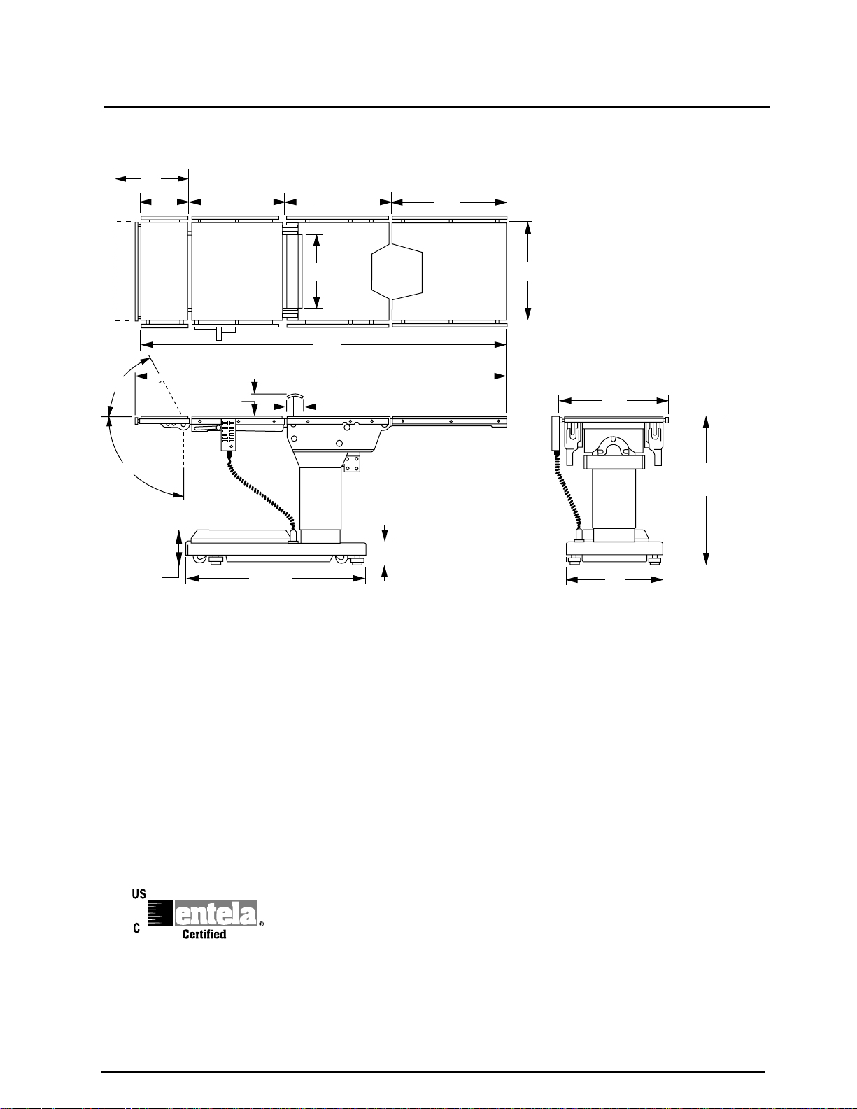
6002 Series General Purpose Surgical Table Specifications
15"
10"
19-1/2"
21-1/2" 24"
60˚
90˚
13"
75"
TOP VIEW
76"
5-3/4"
8"
35-1/2"
3"
5-3/4"
SIDE VIEW
20"
22"
43" MAX.
28" MIN.
19"
END VIEW
Electrical Specifications
Power requirements 120 VAC, 60Hz, 300 Watts
Current Leakage Less than 100 micro amps
Power Cord 15 feet w/hospital grade connector
ENTELA CERTIFIED
TO UL2601-1
CAN/CSA601.1, IEC 60601-2-46
(removeable on battery model)
1
SPECIAL USER ATTENTION
The extreme positioning capabilities of the 6002
Series Table requires special attention for possible
interference points when using multiple function
positioning. As with the operation of any surgical
table, a certain amount of care should be exercised
to position the patient safely. Although the thick
pads and sheets substantially protect the patient,
pinch points, located at the joints of the top section
should always be considered. BE SURE THAT
THE ARMS, HANDS AND FINGERS OF THE
PATIENT AND THOSE OF THE OPERATING
ROOM PERSONNEL ARE CLEAR OF ALL MOVING PARTS BEFORE POSITIONING THE
TABLE. Proper restraints should always be used
for patient safety.
Certain accessories such as the Uro-Drain Tray,
Armboards and X-Ray top can be damaged when
changing the position of the table top sections.
Always look first to see if a desired movement is
going to interfere with any accessories in use.
The operator has the ultimate responsibility of
preventing damage to the table and surrounding
equipment or possible injury to the patient or staff.
In general, common sense will dictate when there
is a potential hazard.
The following precautions should be reviewed
by all personnel prior to operating the table.
WARNING
Risk of electrical shock. Make sure
power cord is disconnected prior to
accessing fuses.
NOTE
Activating any function button will activate the brake system. Using the TABLE
UP function to set the brakes provides
a visual assurance that the brakes are
locked. As the brake cylinders are
extending, the entire table will move
slightly. When the table top begins to
elevate, the brakes are fully locked.
WARNING
DO NOT unlock brakes when a patient
is on the table. An uneven patient
weight load may cause instability.
•Never operate the table without ensuring that the brakes are set.
WARNING
Possible explosion hazard exists if table
is used in the presence of FLAMMABLE
ANESTHETICS.
A routine Instructional Program should be
implemented by the facility for proper usage
instructions for all personel that may operate
this table.
WARNING
Indicates a possibility of personal injury.
CAUTION
Indicates a possibility of damage to
equipment.
NOTE
Indicates important facts or helpful hints.
NOTE
The table will operate correctly on battery power with the power cord connected to a wall outlet or disconnected.
NOTE
Battery Operation must be turned OFF
at the pendant control. It can not be
turned Off using the main power switch.
NOTE
If the table is stored for a period greater
than 6 months, the batteries should be
removed and stored in a dry, clean
condition at a storage temperature of
68° F (20° C). Batteries should be recharged every 6 months of product
storage.
2
SPECIAL USER ATTENTION
NOTE
When the amber light starts to blink
(indicating low power in battery) the table
will operate for approximately 5 continuous minutes, typically long enough to
use the table for the rest of the day.
NOTE
The charging system operates ONLY
when the table is in AC120V operation
mode.
NOTE
The table can be operated on 120VAC
power while the battery is being recharged. The green AC 120V indicator
light (on the pendant control) will illuminate confirming 120VAC operation.
NOTE
The emergency back-up control
switches will function when the table is
operating on 120VAC power, battery
power, or turned off.
WARNING
To maximize patient safety, utilize
proper restraint methods during extreme
Trendelenburg positioning.
WARNING
To maximize patient safety, utilize
proper restraint methods during extreme
lateral tilt positioning.
CAUTION
To prevent damage to the kidney lift,
make sure the kidney lift is completely
down before raising the back section.
WARNING
The Leg section may hit the table base
or the floor if both the leg and elevation
systems are placed in their full down
position.
NOTE
Elevation and brake system functions
are not affected by the return to level
function.
NOTE
The main power switch can be placed in
the OFF position to completely deactivate all table functions if required during
certain procedures or in case of emergency.
NOTE
With an evenly distributed patient weight
load, all table positioning functions will
operate smoothly and quietly with a
patient weight of up to 600 pounds.
Refer to section 3-8 for specialty positioning.
WARNING
DO NOT unlock brakes when a patient
is on the table. An uneven patient
weight load may cause instability.
NOTE
The Emergency Brake Release Valve
must be closed and tightened (clockwise) before activating any function.
•If the Emergency Brake Release Valve
has been operated, the UNLOCK button on the pendant control will have to
be pressed before brakes will lock again.
NOTE
Normal table top position is with the
head (and back) section over the power
cord end of the base.
WARNING
Always lock the table top in position
after rotation. DO NOT rotate the top
with an unevenly distributed patient
weight load as instability may result.
3

SPECIAL USER ATTENTION
WARNING
•Make sure the TOP ROTATION LOCK
HANDLE is tightened and the brakes
are set before transferring the patient.
•Exercise caution with the table top
rotated 90° to the base since an improperly distributed patient load may cause
the table to be tipped over.
CAUTION
To prevent damage to the kidney
lift,make sure the kidney lift is completely down before raising the back
section. See figure 3-18.
WARNING
Consult manufacturer's instructions
when using high frequency surgical
equipment, cardiac defibrillator and cardiac defibrillator monitors.
NOTE
Always follow current AORN Journal
Guidelines to ensure proper cleaning
and disinfection procedure.
CAUTION
Caution should be taken when cleaning
the table to prevent excessive fluid entry into electrical connectors.
WARNING
Always follow OSHA blood-borne pathogens standards for protective clothing,
including gloves, masks and eye protection when cleaning the surgical table.
CAUTION
Thoroughly read and follow the
manufacturer's directions for all cleaning fluids. DO NOT use cleaners containing phenolics.
WARNING
When an antistatic pathway is required,
the table has to be used on an antistatic
floor.
WARNING
The antistatic properties of the table are
dependent on the use of the original pad
set which was furnished with the table
or an alternate approved replacement.
WARNING
Certain accessories may limit weight
capacities, check with your SKYTRON
representative.
WARNING
To ensure patient safety, certain positioning techniques and some accessories should NOT be used when a
patient's weight exceeds 500 pounds.
CAUTION
When using spray cleaners DO NOT
spray fluids directly into electrical receptacles or micro switches.
CAUTION
Before replacing pads on the table, make
sure the pads and all mating surfaces
are completely dry. Moisture trapped
between the pads and mating surfaces
may cause distortion of table tops.
4
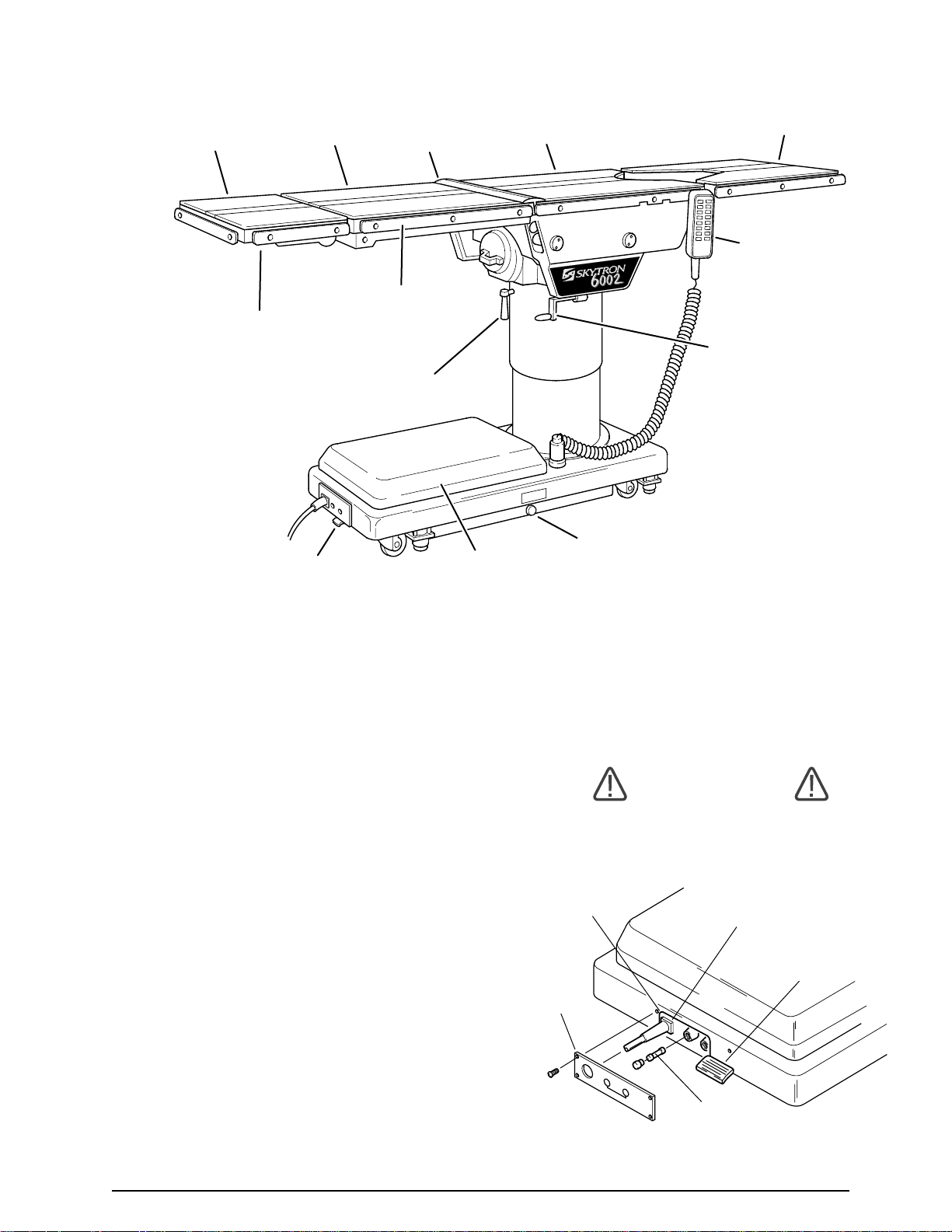
SECTION I INTRODUCTION
ELECTRICAL
ENCLOSURE
POWER
CORD
MAIN POWER
SWITCH
(2) FUSES
10 Amp FA
COVER
PLATE
HEAD
SECTION
HEAD SECTION
RELEASE BAR
(NOT SHOWN)
BACK
SECTION
MAIN POWER
SWITCH
KIDNEY
LIFT
SIDE
RAIL
TOP ROTATION
HANDLE
SERVICE ACCESS
COVER
SEAT
SECTION
LEG
SECTION
PENDANT
CONTROL
KIDNEY LIFT
HAND CRANK
EMERGENCY BRAKE
RELEASE
Figure 1-1. Elite 6002
1-1. General
SKYTRON’s Elite 6002 Series Surgical Tables are
electro-hydraulically operated, general purpose surgical tables. See figure 1-1.
The electro-hydraulic positioning functions operated by the hand-held, push button, pendant control
unit are: trendelenburg, lateral tilt, back section,
elevation, leg section, flex/reflex, return to level, and
the floor lock/brake system.
Manual controls are provided for head section positioning, table top rotation, emergency brake release
and kidney lift.
1-2. Power Requirements
The Elite 6002 Series Surgical Tables require a
120VAC, 60 Hz electrical power supply. The table
is equipped with a 15 foot long power cord with a
standard three prong, hospital grade plug. The
electrical protection fuses are located behind a
cover plate in the electrical enclosure on the front
MODEL 6002
edge of the base. See figure 1-2. The main power
ON/OFF switch is located on the electrical enclosure.
WARNING
Risk of electrical shock. Make sure
power cord is disconnected prior to
accessing fuses.
Figure 1-2. Power Switch and Fuse Location
5

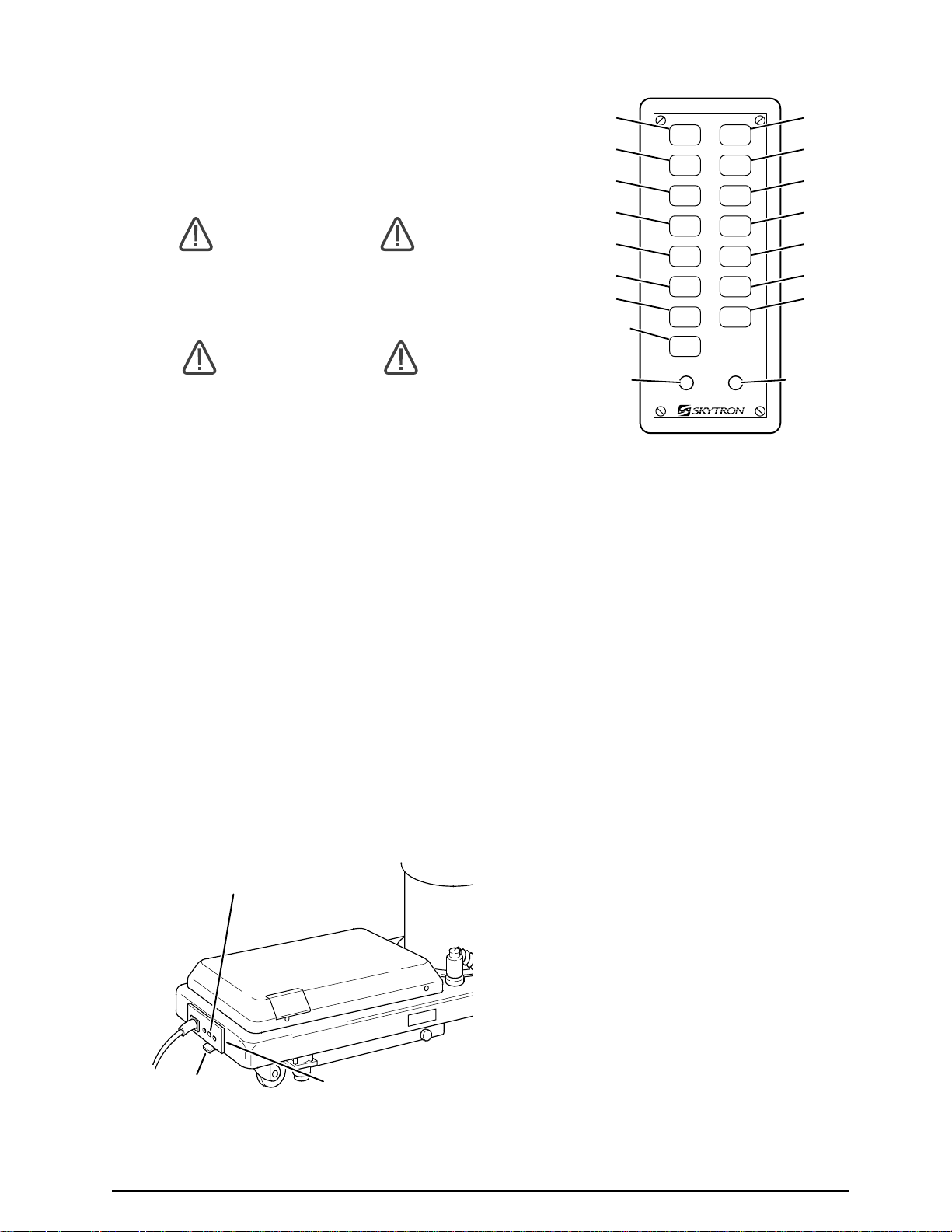
1-3. Pendant Control Unit
The hand-held pendant control unit (figure 1-3) has
a non-slip rubber cover which assures a positive
grip during use. A spring clip hanger is located on
the back of the control for storage. When the
Pendant Control is not in use, it should be stored on
a convenient side or end rail. A bracket is located
under the table top for storage of the Pendant
Control when the table is not in use and during
cleaning. See figure 1-4.
CLIP
TREND
.
REV
TILT
TREND
RIGHT
TILT
BACK
LEFT
BA
TABLE
*
LEG
FLEX
RETURN
PRESS
*
UP
UP
UP
K
C
LOCK BRAKES
TO
DOWN
TABLE
WN
DO
LEG
WN
DO
REFLEX
BRAKE
UNLOCK
WER ON
PO
POWER
INDICATOR
FUNCTION
BUTTONS
The function push buttons are identified with abbreviated descriptions for all functions. See figure 1-
5. The Trendelenburg and table up buttons are red,
the remaining buttons are all black.
REVERSE
TRENDELENBURG
LATERAL
TILT LEFT
BACK UP
TABLE UP
LEG UP
FLEX
RETURN
REV.
TREND
TILT
LEFT
BACK
TABLE
LEG
FLEX REFLEX
RETURN
PRESS TO LOCK BRAKES
UP
UP
UP
TREND
TILT
RIGHT
BACK
DOWN
TABLE
DOWN
LEG
DOWN
BRAKE
UNLOCK
POWER ON
TRENDELENBURG
LATERAL
TILT RIGHT
BACK DOWN
TABLE DOWN
LEG DOWN
REFLEX
BRAKE
RELEASE
POWER ON
INDICATOR
Figure 1-5. Function Push Buttons
1-4. Floor Lock/Brake System
The floor lock/brake system consists of four selfleveling, hydraulic brake cylinders which raise and
support the table base off from the casters. Press
the TABLE UP button on the pendant control to set
the table’s brakes. An electronic timer will activate
the brake system until the brakes are completely
set, approximately 8-10 seconds.
Figure 1-3. Pendant Control Unit
SEAT
BACK
SECTION
SECTION
PENDANT CONTROL
STORAGE BRACKET
TOP ROTATION
HANDLE
Figure 1-4. Pendant Control Storage Bracket
6
NOTE
Activating any function button will activate the brake system. Using the TABLE
UP function to set the brakes provides
a visual assurance that the brakes are
locked. As the brake cylinders are
extending, the entire table will move
slightly. When the table top begins to
elevate, the brakes are fully locked.
To unlock the brakes, press the BRAKE UNLOCK
button and release. The brakes will retract automatically in approximately 7-8 seconds.
WARNING
DO NOT unlock brakes when a patient
is on the table. An uneven patient
weight load may cause instability.
•Never operate the table without ensuring that the brakes are set.
2-1. Introduction
SECTION II BATTERY TABLE CONTROLS
The operation of the 6002B, Battery Model table is
identical to the line powered models except for the
functions required to operate on battery power. The
following section explains the differences for the
battery powered models.
WARNING
Prior to operating the table, observe all
table caution labels and review the
SPECIAL USER ATTENTION section
in the front of this manual.
WARNING
Possible explosion hazard exists if table
is used in the presence of FLAMMABLE
ANESTHETICS.
2-2. Battery Model Table, AC 120V Operation
The battery model tables will operate on either 120
VAC or battery power. Use the following procedures to operate the table on 120 VAC power.
a. Be sure the power cord is plugged into a
properly grounded, Hospital Grade, 120VAC outlet. Make sure the power cord is routed to the outlet
to prevent it from being in the way of operationg
personnel.
b. Activate the POWER SWITCH located on the
electrical panel. See figure 2-1. The green AC120V,
Power-On indicator light located in the lower right
corner of the pendant control will illuminate. See
figure 2-2.
BATTTERY CHARGING
INDICATOR LIGHT
REVERSE
TRENDELENBURG
LATERAL
TILT LEFT
BACK UP
TABLE UP
LEG UP
FLEX
RETURN
BATTERY ON/OFF
SELECTOR BUTTON
BATTERY POWER
INDICATOR LIGHT
(AMBER)
REV.
TILT
LEG
UP
TREND
TILT
RIGHT
DOWN
DOWN
LEG
DOWN
BRAKE
UNLOCK
POWER ON
TREND
LEFT
BACKUPBACK
*
TABLEUPTABLE
FLEX REFLEX
RETURN
BATT
PRESS TO LOCK BRAKES
*
BATTERY
TRENDELENBURG
LATERAL
TILT RIGHT
BACK DOWN
TABLE DOWN
LEG DOWN
REFLEX
BRAKE
RELEASE
AC120V POWER ON
INDICATOR LIGHT
(GREEN)
Figure 2-2. Pendant Control
2-3. Battery Operation
a. Make sure the green, AC 120V, Power-On
indicator light, on the hand-held pendant control, is
OFF. See figure 2-2. If the indicator light is ON,
depress the main power ON/OFF switch, located
on the electrical enclosure to turn AC120V operation OFF.
NOTE
The table will operate correctly on battery power with the power cord connected to a wall outlet or disconnected.
b. Press the BATT button on the hand-held
pendant control. The amber BATTERY indicator
light, located in the lower left corner of the pendant
control, will illuminate. This confirms that the table
is now being operated with battery power.
MAIN POWER SWITCH
Figure 2-1. Main Power Switch
ELECTRICAL ENCLOSURE
c. The table is now ready to operate on battery
power. Refer to Section 3 for operation.
d. To extend the battery charge life, turn the
BATTERY power OFF with the pendant control
when the table is not going to be used.
NOTE
Battery Operation must be turned OFF
at the pendant control. It can not be
turned Off using the main power switch.
7

2-4. Automatic Shut-Off
a. To prevent unnecessary discharge of the
battery, a timer is built into the battery circuit. This
timer will automatically shut the battery power OFF
after 3-4 hours of table inactivity.
b. To turn the table “ON” again, simply press the
BATT button on the pendant control and the amber
indicator light will illuminate. Select any control
button to operate the table.
2-5. Charging the Battery
Batteries should be charged:
•When the table is placed into initial
service
•As indicated by red indicator light blinking
•Every week in normal service
NOTE
If the table is stored for a period greater
than 6 months, the batteries should be
removed and stored in a dry, clean
condition at a storage temperature of
68° F (20° C). Batteries should be recharged every 6 months of product
storage.
b. To recharge the battery simply plug the
power cord into a 120VAC wall outlet, if not
already plugged in. Turn the main power ON/
OFF switch ON by depressing it. The green
battery charging light, located next to the power
cord, will illuminate.
c. A full battery charge will last approximately 2
weeks under normal operating conditions. However, it is recommended to charge the batteries at
the end of each week to establish a normal routine
protocol. Lead acid batteries last longer if they are
not permitted to fully discharge. The table features
(2) 12 volt, sealed, lead acid batteries which require
no manual maintenance. Lead acid gel batteries,
under a proper charging program, feature an approximate normal life of 4 years.
NOTE
The table can be operated on 120VAC
power while the battery is being recharged. The green AC 120V indicator
light (on the pendant control) will illuminate confirming 120VAC operation.
a. If the battery needs to be charged when
operating the table on battery power, the amber
indicator light on the pendant control will begin to
blink. At this time the battery needs to be recharged.
NOTE
When the amber light starts to blink
(indicating low power in battery) the
table will operate for approximately 5
continuous minutes, typically long
enough to use the table for the rest of
the day.
NOTE
The charging system operates ONLY
when the table is in AC120V operation
mode.
8
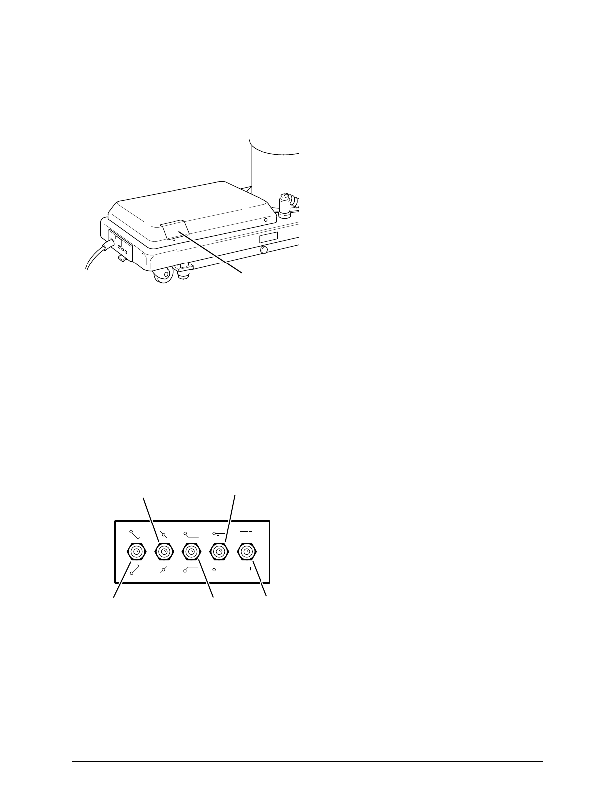
2-6. Emergency Back-up Controls
a. The emergency back-up control switches are
located under the access door on the service
access cover in the table base. See figure 2-3.
FUNCTION CONTROL
ACCESS DOOR
Figure 2-3. Emergency Controls Location
b. In the event of either a power failure or a
problem with the hand-held pendant control, the
table can be operated using the emergency backup switches. Simply push the desired emergency
switch in the appropriate direction to operate the
table functions. See figure 2-4. These switches are
spring-loaded so they return to the neutral or center
position when released.
LA T. TIL T
LEFT/RIGHT
TREND
REV . TREND
TABLE
UP/DOWN
BACK
UP/DOWN
LEG
UP/DOWN
Figure 2-4. Emergency Back-Up Controls
NOTE
The emergency back-up control
switches will function when the table is
operating on 120VAC power, battery
power, or turned off.
9

SECTION III OPERATION
3-1. Electrical Power
a. Check to be sure the power cord is plugged
into a properly grounded, Hospital Grade, 120VAC
outlet. Make sure the power cord is routed so as to
prevent it from being in the way of the operating
personnel.
b. Depress “Main Power ON/OFF” switch on
the electrical enclosure. See figure 3-1. The green
POWER ON indicator light on the pendant control
should now be illuminated.
NOTE
The main power switch can be placed in
the OFF position to completely deactivate all table functions if required during
certain procedures or in case of emergency.
MAIN
POWER
CORD
POWER SWITCH
NOTE
With an evenly distributed patient weight
load, all table positioning functions will
operate smoothly and quietly with a
patient weight of up to 600 pounds.
Refer to section 3-8 for speciality positioning.
a. Floor Lock/Brake System. To activate
the brakes without affecting table positioning, press
the TABLE UP button. See figure 3-3. The
elevation cylinder will not function until the brakes
are completely extended.
REV.
TREND
TREND
TILT
TABLE UP
TILT
LEFT
RIGHT
BACK
BACK
DOWN
UP
TABLE
TABLE
DOWN
UP
LEG
LEG
DOWN
UP
FLEX REFLEX
BRAKE
RETURN
UNLOCK
PRESS TO LOCK BRAKES
POWER ON
BRAKE
RELEASE
ELECTRICAL
ENCLOSURE
Figure 3-1. Main Power Switch
3-2. Positioning Functions
The hand-held pendant control (figure 3-2) activates the following table functions:
REVERSE
TRENDELENBURG
LATERAL
TILT LEFT
BACK UP
TABLE UP
LEG UP
FLEX
RETURN
REV.
TREND
TABLE
RETURN
PRESS TO LOCK BRAKES
TREND
TILT
LEFT
BACK
LEG
FLEX REFLEX
TILT
RIGHT
BACK
DOWN
UP
TABLE
DOWN
UP
LEG
DOWN
UP
BRAKE
UNLOCK
POWER ON
TRENDELENBURG
LATERAL
TILT RIGHT
BACK DOWN
TABLE DOWN
LEG DOWN
REFLEX
BRAKE
RELEASE
POWER ON
INDICATOR
Figure 3-2. Pendant Control Unit
10
Figure 3-3. Brake System Activation
Press the BRAKE UNLOCK button on the pendant control to release the four self-leveling brake
feet in order to move the table. See figure 3-3. The
brake delay circuit automatically retracts the brake
system with just one press of the BRAKE UNLOCK button. It takes approximately 7-8 seconds
to totally release the system.
WARNING
DO NOT unlock brakes when a patient
is on the table. An uneven patient
weight load may cause instability.
b. Trendelenburg. To place the surgical table
in a Trendelenburg (head down) position, press
the TREND button (figure 3-4). Trendelenburg
positioning of up to 30° may be obtained. To place
the table in a reverse trendelenburg (head up)
position, press the REV TREND button. Reverse
Trendelenburg positioning of up to 30° may be obtained.

WARNING
CAUTION
To maximize patient safety, utilize
proper restraint methods during extreme Trendelenburg positioning.
REV.
TREND
TREND
TILT
TILT
LEFT
RIGHT
BACK
BACK
DOWN
REVERSE
TRENDELENBURG
UP
TABLE
TABLE
DOWN
UP
LEG
LEG
DOWN
UP
FLEX REFLEX
BRAKE
RETURN
UNLOCK
PRESS TO LOCK BRAKES
POWER ON
TRENDELENBURG
30˚
30˚
Figure 3-4. Trendelenburg Positioning
c. Lateral Tilt. To achieve lateral tilt right (as
viewed from the head end of the table), press the
TILT RIGHT button (figure 3-5). Tilt of up to 30° may
be obtained. To achieve lateral tilt left, press the
TILT LEFT button. Tilt of up to 30° may be obtained.
To prevent damage to the kidney lift,
make sure the kidney lift is completely
down before raising the back section.
d. Back Section. To raise the back section,
press the BACK UP button (figure 3-6). The back
section will raise up to 90° above horizontal. To
lower the back section, press the BACK DOWN
button. The back section will go down to 40° below
horizontal.
40˚
90˚
BACK UP
REV.
TREND
TREND
TILT
TILT
LEFT
RIGHT
BACK
BACK
DOWN
UP
TABLE
TABLE
DOWN
UP
LEG
LEG
DOWN
UP
FLEX REFLEX
BRAKE
RETURN
UNLOCK
PRESS TO LOCK BRAKES
POWER ON
BACK DOWN
Figure 3-6. Back Section Positioning
WARNING
To maximize patient safety, utilize
proper restraint methods during extreme
lateral tilt positioning.
REV.
TREND
TREND
TILT
TILT
LEFT
RIGHT
BACK
BACK
DOWN
UP
TABLE
TABLE
DOWN
LATERAL
TILT LEFT
UP
LEG
LEG
DOWN
UP
FLEX REFLEX
BRAKE
RETURN
UNLOCK
PRESS TO LOCK BRAKES
POWER ON
30˚ 30˚
LATERAL
TILT RIGHT
e. Elevation. To raise table top, press the
TABLE UP button (figure 3-7). The table will lift a
patient weight of 600 pounds up to a maximum
height of 43". To lower the table top, press the
TABLE DOWN button. The table top will go down
to a minimum height of 28".
43"
TABLE-UP
28"
REV.
TREND
TREND
TILT
TILT
LEFT
RIGHT
BACK
BACK
DOWN
UP
TABLE
TABLE
DOWN
UP
LEG
LEG
DOWN
UP
FLEX REFLEX
BRAKE
RETURN
UNLOCK
PRESS TO LOCK BRAKES
POWER ON
TABLE-DOWN
Figure 3-5. Lateral Tilt Positioning
Figure 3-7. Elevation Function
11

f. Leg Section. To lower the leg section press
the LEG DOWN button (figure 3-8). The leg section
will go down to 105° below horizontal. To raise the
leg section, press the LEG UP button. The leg
section will go up to horizontal.
REV.
TREND
TREND
TILT
TILT
LEFT
RIGHT
BACK
BACK
DOWN
LEG UP
UP
TABLE
TABLE
DOWN
UP
LEG
LEG
DOWN
UP
FLEX REFLEX
BRAKE
RETURN
UNLOCK
PRESS TO LOCK BRAKES
POWER ON
LEG DOWN
g. Flex Positioning. To place the table top in a
flex position from horizontal, press the FLEX button
(figure 3-9). To return the table top to a horizontal
position or into a reflex position, press the RETURN or REFLEX button.
REV.
TREND
TREND
TILT
TILT
LEFT
RIGHT
BACK
BACK
DOWN
FLEX
UP
TABLE
TABL E
DOWN
UP
LEG
LEG
DOWN
UP
FLEX REFLEX
BRAKE
RETURN
UNLOCK
PRESS TO LOCK BRAKES
POWER ON
REFLEX
105˚
Figure 3-8. Leg Section Positioning
WARNING
The Leg section may hit the table base
or the floor if both the leg and elevation
systems are placed in their full down
position.
Figure 3-9. Flex/Reflex Positioning
h. Return To Level. To return the table top to
a level position, press the RETURN button (figure
3-10).
NOTE
Elevation and brake system functions
are not affected by the return to level
function.
REV.
TREND
TREND
RETURN
TO LEVEL
TILT
LEFT
BACK
TABLE
LEG
FLEX REFLEX
RETURN
PRESS TO LOCK BRAKES
TILT
RIGHT
BACK
DOWN
UP
TABLE
DOWN
UP
LEG
DOWN
UP
BRAKE
UNLOCK
12
POWER ON
Figure 3-10. Return To Level
LEG
SECTION
HEAD
SECTION
LOCKING
KNOB
LOCKING
KNOB
i. Pendant Control Storage. When the Pendant Control is not in use, it should be stored on a
convenient side or end rail. A bracket is located
under the table top for storage of the Pendant
Control when the table is not in use and during
cleaning. See figure 3-11.
PENDANT CONTROL
STORAGE BRACKET
Figure 3-11. Pendant Control Storage
Bracket
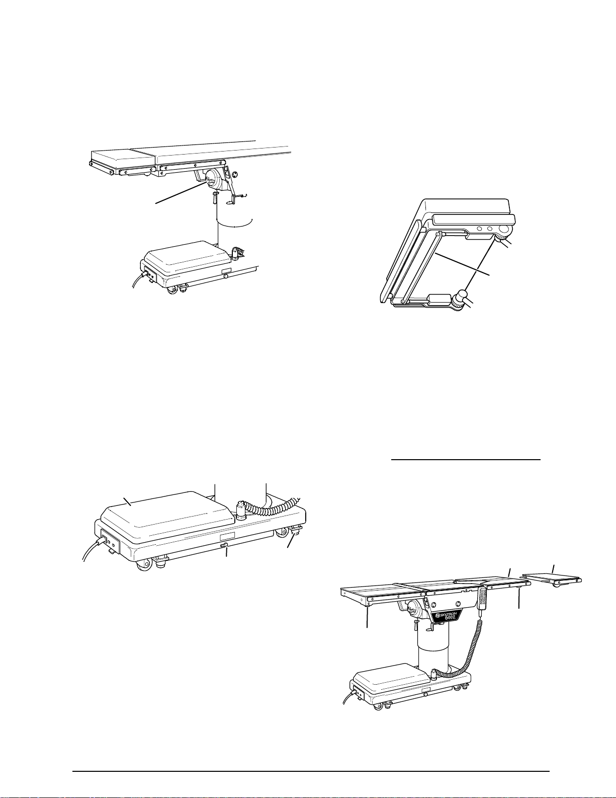
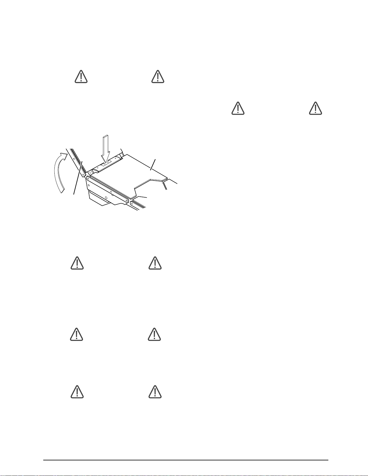
3-3. Emergency Brake Release.
3-4. Head Section
a. A quick release positioning bar located under
and to the front of the head section (figure 3-13) is
used to raise or lower the head section. Pull the
release bar toward the head end to allow the
section to pivot up or down. Positioning from 75°
above horizontal to 90° below horizontal in 15°
increments is available. Release the bar to lock the
head section in position.
HEAD SECTION
RELEASE BAR
Figure 3-13. Head Section Adjustment
In case of a power failure or an electrical problem
within the table, the emergency brake release
system can be used to move the table. The control
lever for this function is located on the side of the
table base and is identified by an EMERGENCY
BRAKE RELEASE label. Turn the lever counterclockwise to release the brakes. See figure 3-12.
SERVICE
ACCESS COVER
EMERGENCY
BRAKE RELEASE
BRAKE (4)
Figure 3-12. Emergency Brake Release
NOTE
The Emergency Brake Release Valve
must be closed and tightened (clockwise) before activating any function.
b. By loosening two locking knobs beneath the back
section, an additional 5" of longitudinal adjustment
can be achieved. If desired, the head section may be
removed by loosening the locking knobs and pulling
it straight out of the back section. 6002 Series Tables
have the capability of attaching the head section to the
leg section
for use as a foot extension ONLY. Do Not
reverse the patient on the table without first consulting
with SKYTRON. Two locking knobs are located on
the inside of the leg section for securing the head
section. See figure 3-14.
•If the Emergency Brake Release Valve
has been operated, the UNLOCK button on the pendant control will have to
be pressed before brakes will lock
again.
Figure 3-14. Repositioning Head Section
13
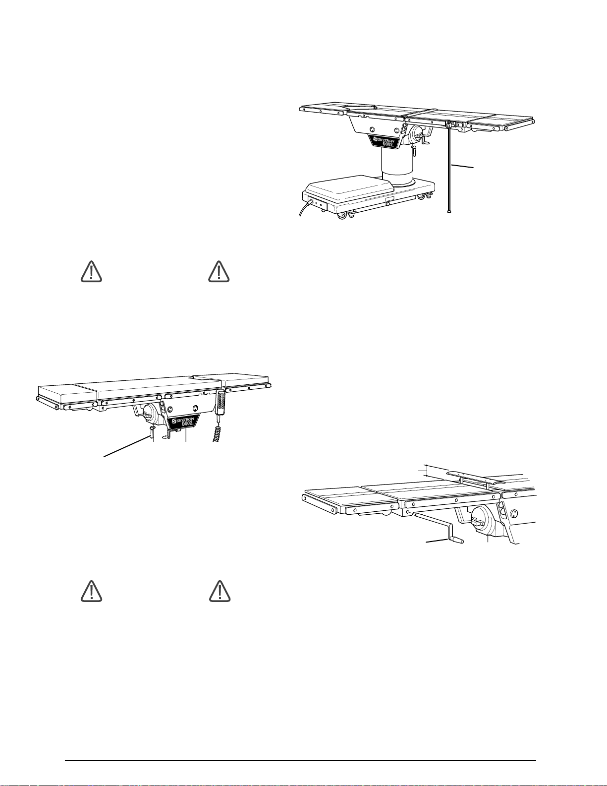
3-5. 180 Degree Table Top Rotation.
NOTE
Normal table top position is with the
head (and back) section over the power
cord end of the base.
a. The table top can be horizontally rotated 180°
without having to rotate the entire table. To rotate
the top, turn the TOP ROTATION LOCK HANDLE
counterclockwise (figure 3-15), grasp the table by
the head end and rotate the top 180° counterclockwise. Lock the top in position by tightening the TOP
ROTATION LOCK HANDLE clockwise.
SUPPORT
ROD
WARNING
Always lock the table top in position
after rotation. DO NOT rotate the top
with an unevenly distributed patient
weight load as instability may result.
TOP ROTATION
LOCK HANDLE
Figure 3-15. 180 Degree Top Rotation
b. The use of the optional support rod allows
the table top to be rotated 90° from the base. See
figure 3-16.
Figure 3-16. 90 Degree Top Rotation
3-6. Kidney Lift
a. The built-in kidney lift is operated by a manual
hand crank system and allows 5-3/4 inches of lift.
See figure 3-17. The hand crank is stored in a
bracket on the lower right hand side frame (as
viewed from the head end of the table).
5-3/4" MAX
HAND CRANK
WARNING
•Make sure the TOP ROTATION LOCK
HANDLE is tightened and the brakes
are set before transferring the patient.
•Exercise caution with the table top
rotated 90° to the base since an improperly distributed patient load may cause
the table to be tipped over.
14
Figure 3-17. Optional Kidney Lift
b. To operate, connect the handle to the drive
mechanism on right side of the back section. Rotate the handle clockwise to raise the lift and
counterclockwise to lower it.
CAUTION
To prevent damage to the kidney lift,
make sure the kidney lift is completely
down before raising the back section.
See figure 3-18.
SEAT
SECTION
BACK
SECTION
3-7. Positioning
The use of certain optional accessories available
from SKYTRON further extend the positioning
capabilities of the 6002 Series Tables. Refer to the
following "Positioning Guidelines" or contact your
SKYTRON representative for further details.
WARNING
Certain accessories may limit weight
capacities. check with your SKYTRON
representative.
Refer to paragraph 3-8 for specialty accessories
and positioning for patients over 500 lbs.
Figure 3-18.
WARNING
Consult manufacturer's instructions
when using high frequency surgical
equipment, cardiac defibrillator and cardiac defibrillator monitors.
WARNING
When an antistatic pathway is required,
the table has to be used on an antistatic
floor.
WARNING
The antistatic properties of the table are
dependent on the use of the original pad
set which was furnished with the table
or an alternate approved replacement.
15

6002 Series Patient Positioning Guidelines
Upper Body Imaging Accessories: "L" Type Anesthesia
Screen, Standard Armboard and 2" Pad, Snap Strap, 10"
foot Extension and 2" Pad.
Lap Nissen Accessories: Multi-Task Armboard with
Pad, Nissen Strap, Levitator Stirrups.
Lower Body Imaging Accessories: Multi-Task Armboard
with Pad, Snap Strap, 10" Foot Extension and 2" Pad.
Ureteroscopy/Cysto Accessories: Mult-Task Armboard
with Pad, Levitator Stirrups, Uro Catcher, Uro Catcher
Pouch.
OB/GYN Accessories: Raised Armboard, Ankl-Lock
Stirrups, 10" Foot Extension.
16
Ophthalmic/ENT Accessories: Standard Armboard
and 2" Sof-Pad, 10" Foot Extension and 2" Pad.

6002 Series Patient Positioning Guidelines
Thoracic/Kidney Accessories: Standard Armboard,
and 2" Pad, Multi-Task Armboard with Pad, Snap Strap,
Chest & Waist Supports, 10" Foot Extension and 2" Pad.
Shoulder Accessories: Shoulder Arthroscopy Positioner,
Lateral Brace, Multi-Task Armboard with Pad, Restraint
Strap, 10" Foot Extension, and 2" Pad.
Neurosurgery Accessories: Multi-Task Armboard with
Pad, Snap Strap, 10" Foot Extension, and 2" Pad.
Hip Accessories: Multi-Task Armboard with Pad,
Standard Armboard and 2" Pad, Restraint Strap, Chest
& Waist Supports.
Lumbar Accessories: Multi-Task Armboard with Pad,
Safety Strap.
Vascular/Orthopedic Accessories: Multi-Task
Armboard with Pad, Universal Split Leg with 2" Pad (pr).
17

3-8. Specialty Positioning
WARNING
To ensure patient safety, certain positioning techniques and some accessories should NOT be used when a
patient's weight exceeds 500 pounds.
DO
•Do use patient restraints on all patients.
•Do use "Positioning Guidelines" ONLY for patients under 500 pounds.
•Do use table side extensions (3-060-02) to widen
table to 27" when necessary.
•Do use Sof-Pads (1-010-22-5) or PHD pads (1010-22-PHD) whenever possible but especially if
patient weight is over 500 pounds.
•Do use Levitator Stirrups (4-090-03-1) or knee
crutches (4-010-01-1).
•Do use 105" restraint strap (6-010-41-X)
DON'T
This list is not limited to the items listed below
•Don't use normal positioning techniques with patients over 500 pounds
•Don't reverse the patient on the table if patient
weight is over 500 pounds
•Don't use the following accessories if patient weight
is over 500 pounds:
•Transfer Board
•18" Knee rest
•Lithotomy Stirrups
•Ankle-Lock Lithotomy Stirrups
•Kidney Horns
•Shoulder Arthroscopy Positioner
•Prone Positioning Frame
18
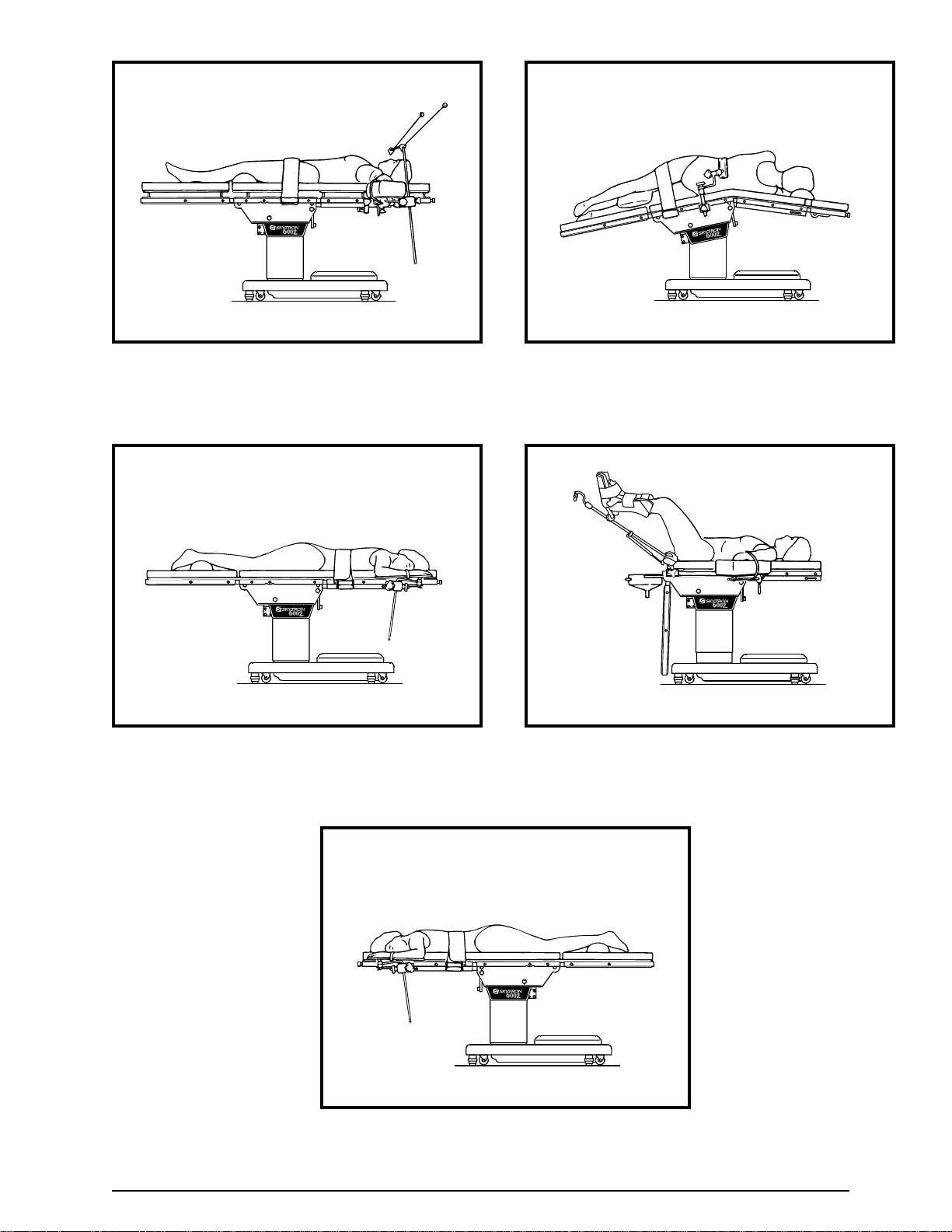
MODEL 6002 Positioning for Patient Weight Exceeding 500 Pounds
Supine Basic Position
Prone Basic Position Lithotomy Basic Position
Lateral Basic Position
Prone Supine Position Rotated 180°
19

SECTION IV MAINTENANCE
4-1. Preventive Maintenance
The following preventive maintenance checks and
services are recommended to ensure the serviceability and proper operation of your SKYTRON
Surgical Table.
a. During normal cleaning, a general visual
examination should be made checking for leaks,
loose bolts or parts, and cracked, chipped, or
missing paint. Any necessary repairs should be
made.
b. Semi-annually the following checks and
services should be performed:
Place table top in level position prior to starting
cleaning procedure.
WARNING
Always follow OSHA blood-borne pathogens standards for protective clothing,
including gloves, masks and eye protection when cleaning the surgical table.
1. Check all hydraulic fittings, mini-valves and
slave cylinders for proper operation and
any signs of leaks.
2. Check the hydraulic speed controls and
adjust if necessary.
3. Pressure check (with a gauge) the pressure relief valve.
4. Check all mechanical adjustments and adjust as necessary.
5. Check hydraulic fluid level.
6. Lubricate the slider assembly.
4-2. Cleaning Recommendations
NOTE
Always follow current AORN Journal
Guidelines to ensure proper cleaning
and disinfection procedure.
Remove major contaminants from the table with
disposable materials following appropriate biohazard waste disposal procedures.
Remove all table pads and place them on a flat
surface for cleaning.
CAUTION
Thoroughly read and follow the
manufacturer's directions for all cleaning fluids. DO NOT use cleaners containing phenolics.
Apply cleaning fluid liberally to top and sides of
each pad and wipe with a clean lint-free cloth.
Using a clean, damp, lint-free cloth, wipe the pads
to remove the cleaning fluid.
Using a clean, dry, lint-free cloth, wipe the pads to
remove all moisture.
Repeat the steps to clean the bottom of the each
pad.
CAUTION
Caution should be taken when cleaning
the table to prevent excessive fluid entry into electrical connectors.
The following procedures should be followed when
cleaning the surgical table between cases.
20

CAUTION
When using spray cleaners DO NOT
spray fluids directly into electrical receptacles or micro switches.
Repeat cleaning procedure for all table surfaces
including the top, sides, elevation column, base
and all accessories.
CAUTION
Before replacing pads on the table, make
sure the pads and all mating surfaces
are completely dry. Moisture trapped
between the pads and mating surfaces
may cause distortion of table tops.
When the cleaning procedure is complete, replace
all pads and accessories as applicable.
Remove pendant control from table side rail and
apply cleaning solution to the pendant control and
cord.
Use a clean cloth dampened with water to remove
cleaning solution.
Use another clean damp cloth to remove any
remaining residue.
4-3. Service
Table maintenance can be performed by trained
maintenance personnel using SKYTRON authorized replacement parts and service techniques.
Service instructions and parts are available from
SKYTRON.
Preventive Maintenance contracts are available
through your local SKYTRON representative.
To obtain service instructions, replacement parts,
factory service or preventive maintenance contracts, contact your nearest SKYTRON representative or write or call:
SKYTRON
5000 36th Street S.E.
Grand Rapids, MI 49512
1-800-SKYTRON (1-800-759-8766)
Fax. 1-616-957-5053
Install pendant control on side rail for storage when
cleaning procedure is complete.
21
Page 37
Item Part No. Description Qty.
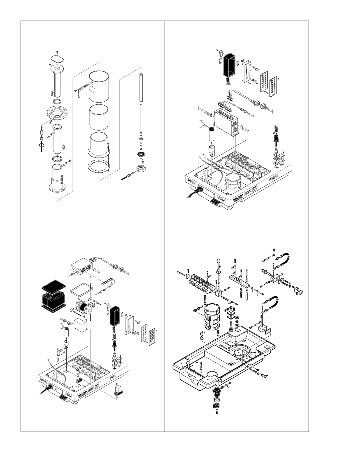
PARTS CATALOG
6002 SERIES SURGICAL TABLES
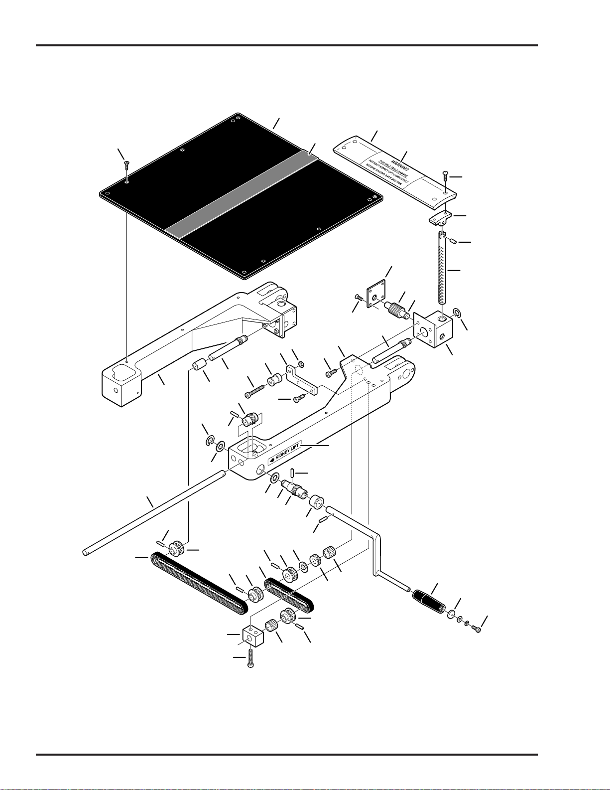
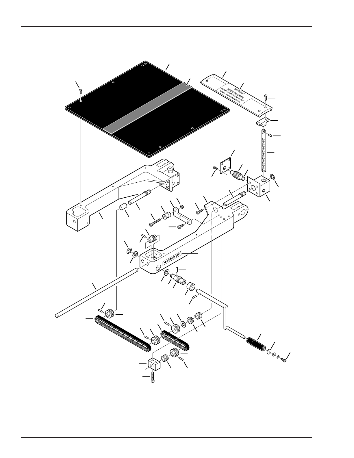
KIDNEY LIFT
KIDNEY LIFT
KIDNEY LIFT
KIDNEY LIFT
KIDNEY LIFT
KIDNEY LIFT
KIDNEY LIFT
KIDNEY LIFT
REV 4-05

Page 1
Item Part No. Description Qty.
INTRODUCTION
This manual contains the exploded views and replacement parts lists for the serviceable components of the SKYTRON Model 6002 Surgical Table.
Each serviceable part in these exploded views is identified by a reference number.
Use this number to locate necessary part information in the parts list adjacent to the
exploded view.
Always use the complete SKYTRON part number and description when ordering
replacement parts.
Always use the complete table serial number (S.N.) when ordering replacement
parts.
Special Tools and Maintenance Items listed on page 34.
Abbreviations
As Required .......................................... A/R
Optional................................................... opt
Serial Number ....................................... S.N.
All Later S.N.'s ......................................... &L
All Prior S.N.'s .......................................... &P
Not Shown............................................... NS
REV 4/05
Although current at the time of publication, SKYTRON's policy of continuous development makes this
manual subject to change without notice.

Page 39Page i
1. Top & Side Frame Assemblies ................................... Page 2 2. Kidney Lift Assembly ............................................... Page 6
Item Part No. Description Qty.
8
KIDNEY LIFT
3. Side Frame & Hydraulic Cylinders......................Page 10 4.Trendelenburg & Lateral Tilt Cylinders ............... Page 14
Page 40
Page ii
5. Support Column Assembly ................................Page 16 6. Electrical Components ........................................ Page 18
7. Electrical Components, Battery Model ............ Page 20 8. Hydraulic Valves & Fittings ................................. Page 24

Page 41Page iii
Item Part No. Description Qty.
9. Electro / Mini Valve Assembly............................Page 28 10. Base Assembly ...................................................Page 30

Page 2
1
1. TOP & SIDE FRAME ASSEMBLIES
28
27
2
3
4
1
13
6
5
7
12
8
11
10
4
16
26
15
7
17
18
19
14
9
25
58
13
20
30
KIDNEY LIFT
13
31
32
7
29
8
10
41
39
12
21
24
8
12
10
14
10
23
33
4
22
34
40
35
36
37
38
50
49
8
44
43
46
47
48
53
54
45
42
8
52
51
8
55
56
57
10
6002.0403.00
10

1. TOP & SIDE FRAME ASSEMBLIES
Item Part No. Description Qty.
1-010-22-P PAD SET, regular........................................................................................................ opt
1-010-22-S PAD SET, soft ............................................................................................................. opt
1 D3-031-37 TOP, seat section..........................................................................................................1
2 D3-030-03 TOP, foot/leg section.....................................................................................................1
3 D3-010-18-H VELCRO, hook (specify length) ..................................................................................A/R
4 D3-010-19 SCREW, phillips hd. ....................................................................................................A/R
5 D3-031-64 FRAME, foot/leg section................................................................................................1
6 D6-031-23 RUBBER STOP, foot/leg section ..................................................................................1
7 D6-032-34 NUT, M8 w/lockwasher................................................................................................A/R
8 D3-010-01 COLLAR, side rail........................................................................................................A/R
9 D6-031-01 KNOB, locking ...............................................................................................................2
10 D6-010-12 SCREW, allen, M8x45 .................................................................................................A/R
11 D3-030-10 RAIL, side, foot/leg section, right...................................................................................1
D3-030-09 RAIL, side, foot/leg section, left .....................................................................................1
12 D3-010-41 PIN, rail stop ..................................................................................................................6
13 D3-010-43 STOP, rail, large ............................................................................................................6
14 D6-010-03 PIN, tapered, spur gear, M7x40 ....................................................................................8
15 D3-031-01 LEVER, axis, foot/leg section ........................................................................................2
16 D3-131-01 BUSHING, foot/leg section lever ...................................................................................2
17 D6-010-50 SCREW, set, M6x15......................................................................................................4
18 D3-131-02 FRAME, side, right ........................................................................................................1
D3-131-03 FRAME, side, left ..........................................................................................................1
19 D3-030-05 AXIS, foot/leg section ....................................................................................................2
20 D3-030-08 RAIL, side, seat section, right........................................................................................1
D3-030-07 RAIL, side, seat section, left ..........................................................................................1
21 D3-010-04 AXIS, back section ........................................................................................................2
22 D6-010-70 BOLT, allen, M5x10 .......................................................................................................2
23 D3-031-61-L BRACKET, crank storage ..............................................................................................1
24 D6-031-31 DECAL, SKYTRON 6002 ..............................................................................................2
D6-031-32 DECAL, SKYTRON 6002B ............................................................................................2
25 D6-010-77-1 WASHER, lock, M5 .......................................................................................................2
26 D6-010-76-1 NUT, M5 ........................................................................................................................2
27 D3-031-28 GEAR, spur, back section .............................................................................................2
28 ----- BUSHING, back section spur gear (not available separately).......................................2
29 D3-031-15 FRAME, back section, right ...........................................................................................1
D3-031-16 FRAME, back section, left .............................................................................................1
30 D6-031-66 SCREW, set, M5x10......................................................................................................2
31 D3-031-82 BUSHING ......................................................................................................................2
32 D3-031-83 KNOB, head rest ...........................................................................................................2
33 D3-031-62 SIDE RAIL, back section, right ......................................................................................1
D3-031-63 SIDE RAIL, back section, left ........................................................................................1
34 D3-032-04 TOP, head section.........................................................................................................1
35 D6-010-38 BOLT, allen, M6x15 .......................................................................................................2
36 D6-010-40 WASHER, lock, M6 .......................................................................................................2
37 D6-010-41 SCREW, set, M8x15......................................................................................................2
38 D3-032-05 FRAME, head section ...................................................................................................1
39 D6-010-38 BOLT, allen, M6x15 .......................................................................................................4
40 D6-010-40 WASHER, lock, M6 .......................................................................................................4
41 D3-010-20 RAIL, accessory ............................................................................................................1
Page 3

Page 4
1
1. TOP & SIDE FRAME ASSEMBLIES (continued)
28
27
2
3
4
1
13
6
5
7
12
8
11
10
4
16
26
15
7
17
18
19
14
9
25
58
13
20
30
KIDNEY LIFT
13
31
32
7
29
8
10
41
39
12
21
24
8
12
10
14
10
23
33
4
22
34
40
35
36
37
38
50
49
8
44
43
46
47
48
53
54
45
42
8
52
51
8
55
56
57
10
6002.0403.00
10

1. TOP & SIDE FRAME ASSEMBLIES (continued)
Item Part No. Description Qty.
42 D6-010-08 NUT, acorn, M8 .............................................................................................................2
43 D6-010-09 WASHER, lock, M8 .......................................................................................................2
44 D3-010-24 RELEASE BAR, head section .......................................................................................1
45 D6-010-13 NUT, M8 ........................................................................................................................2
46 D3-032-40 BLOCK, bearing ............................................................................................................2
47 D6-010-11 SCREW, set, M5x8........................................................................................................2
48 D3-010-26 SPRING, release ...........................................................................................................2
49 D6-050-33 PIN, roll, M5x20 ...........................................................................................................A/R
50 D3-010-27 PLUNGER, release .......................................................................................................2
51 D4-010-14 O-RING, P-12 ................................................................................................................2
52 D3-010-31-1 SHAFT, extension, head section (roll pin) .....................................................................2
53 D3-032-80 GEAR, trunnion, right ....................................................................................................1
D3-032-81 GEAR, trunnion, left ......................................................................................................1
54 D6-010-13 NUT, M8 ........................................................................................................................2
55 D3-031-67-1 RAIL, side, head section ...............................................................................................2
56 D3-034-22 BUSHING, head section ................................................................................................2
57 D6-010-53 BOLT, allen, M8x20 .......................................................................................................2
58 D6-010-50 SCREW, set, M6x15......................................................................................................2
Page 5
Page 6
2
9
2. KIDNEY LIFT ASSEMBLY
1
2
4
3
5
6
7
8
50
30
27
25
28
51
26
29
25
25
16
24
22
45
44
21
31
25
23
20
33
43
34
19
42
35
36
25
18
41
17
32
40
10
16
11
9
12
13
14
15
37
38
49
48
47
46
3
25
6002.0403.00

Page 72. KIDNEY LIFT ASSEMBLY
Item Part No. Description Qty.
1 D3-010-19 SCREW, phillips hd. ....................................................................................................A/R
2 D3-031-65 TOP, back section .........................................................................................................1
3 D3-010-18-H VELCRO, hook (specify length) ..................................................................................A/R
4 D3-031-77 TOP, kidney lift ..............................................................................................................1
5 D6-031-57 DECAL, kidney bridge warning .....................................................................................1
6 D6-031-52 SCREW, round hd. ........................................................................................................4
7 D3-031-39 PIVOT ASSEMBLY .......................................................................................................2
8 D6-031-24 PIN, roll, M5x12 .............................................................................................................2
9 D3-031-40 SHAFT, elevation ..........................................................................................................2
10 D6-031-05 SCREW, phillips, M4x10 ...............................................................................................8
11 D3-031-43 COVER, gear housing, right ..........................................................................................1
D3-031-44 COVER, gear housing, left ............................................................................................1
12 D3-031-45 GEAR ............................................................................................................................2
13 D3-031-46 SHAFT, gear..................................................................................................................2
14 D6-031-62 CIRCLIP, E7 ................................................................................................................A/R
15 D3-031-41-1 HOUSING, gear, right....................................................................................................1
D3-031-42-1 HOUSING, gear, left ......................................................................................................1
16 D3-031-02 WORM GEAR, S.N.6002-019 & L/6002B-008 & L. .......................................................2
D3-031-03 WORM GEAR, S.N.6002-018 & P/6002B-007 & P. ......................................................2
17 D3-031-15 FRAME, back section, right ...........................................................................................1
18 D6-031-63 BOLT, allen, M6x15 .......................................................................................................3
D6-031-64 BOLT, allen, M6x20 .......................................................................................................4
19 D6-010-41 NUT, M6 ........................................................................................................................1
20 D3-031-98 BRACKET......................................................................................................................1
21 D3-010-13 IDLER, S.N.6002-019 &L/6002B-008 & L .....................................................................1
D3-010-14 IDLER, S.N.6002-018 & P/6002B-007 & P....................................................................1
22 D6-010-39-1 BOLT, allen, M6x45, S.N.6002-019 & L/6002B-008 & L ...............................................1
D6-031-67 BOLT, allen, M6x40, S.N.6002-018 & P/6002B-007 & P ..............................................1
23 D6-010-91 BOLT, allen, M6x25 .....................................................................................................A/R
24 D3-031-93 GEAR, drive, S.N.6002-019 & L/6002B-008 & L ...........................................................1
D3-031-94 GEAR, drive, S.N.6002-018 & P/6002B-007 & P ..........................................................1
25 D6-050-33 PIN, roll, M5x20 ...........................................................................................................A/R
26 D3-031-95 COLLAR, S.N.6002-019 & L/6002B-008 & L.................................................................1
D3-031-96 COLLAR, S.N.6002-018 & P/6002B-007 & P ................................................................1
27 D3-031-16 FRAME, back section, left .............................................................................................1
28 D6-010-07 CIRCLIP, E10 ................................................................................................................1
29 D6-031-65 WASHER .......................................................................................................................1
30 D3-031-84 SHAFT, gear, S.N.6002-019 & L/6002B-008 & L ..........................................................1
D3-031-52 SHAFT, gear, S.N.6002-018 & P/6002B-007 & P .........................................................1
31 D3-031-81 WASHER, delrin ............................................................................................................1
32 D6-031-54 DECAL, kidney lift .........................................................................................................1
33 D3-031-80 SHAFT, drive gear .........................................................................................................1
34 D3-031-53 GEAR , drive .................................................................................................................1
35 D3-031-79 BUSHING ......................................................................................................................1
36 D6-031-11 PIN, roll, M5x17 .............................................................................................................1
D3-031-60 HANDLE ASSEMBLY, k-lift crank .................................................................................1
37 D3-031-56 •HANDLE, k-lift crank ....................................................................................................1
38 D6-031-12 •WASHER, flat, M5 (plated) ..........................................................................................1
39 D6-010-28-1 •BOLT, allen, M5x6 (plated) ..........................................................................................1
Page 8
2
9
2. KIDNEY LIFT ASSEMBLY (continued)
1
2
4
3
5
6
7
8
50
30
27
25
28
51
26
29
25
25
16
24
22
45
44
21
31
25
23
20
33
43
34
19
42
35
36
25
18
41
17
32
40
10
16
11
9
12
13
14
15
37
38
49
48
47
46
3
25
6002.0403.00

2. KIDNEY LIFT ASSEMBLY (continued)
Item Part No. Description Qty.
40 D3-010-15 BUSHING, S.N.6002-019 & L/6002B-008 & L...............................................................1
D3-010-16 BUSHING, S.N. 6002-018 & P/6002B-007 & P .............................................................1
41 D3-031-91 BEARING, thrust ...........................................................................................................1
42 D3-031-92 COLLAR ........................................................................................................................1
43 D3-031-90 PULLEY, S.N.6002-019 & L/6002B-008 & L .................................................................1
44 D3-031-86 BELT .............................................................................................................................1
45 D3-031-88 PULLEY, S.N.6002-019 & L/6002B-008 & L .................................................................1
D3-031-89 PULLEY, S.N.6002-018 & P/6002B-007 & P ................................................................1
46 D3-031-85 PULLEY .........................................................................................................................1
47 D3-031-78 BEARING, needle..........................................................................................................1
48 D6-031-59-1 BOLT, allen, M6x40 .......................................................................................................2
49 D3-031-51 BLOCK, guide................................................................................................................1
50 D3-031-87 BELT .............................................................................................................................1
51 D3-031-97 PULLEY .........................................................................................................................1
Page 9

Page 10
3
8
2
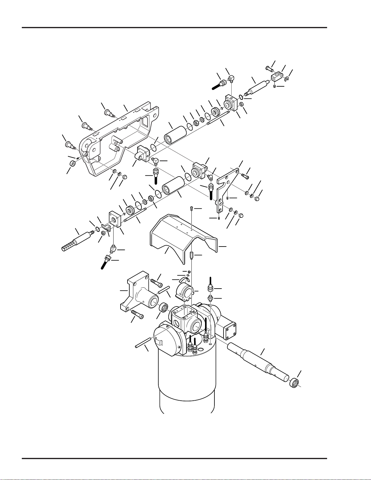
3. SIDE FRAME & HYDRAULIC CYLINDERS
13
14
15
18
17
1
16
6
7
8
9
26
26
27
10
8
11
5
8
5
2
3
4
24
17
34
33
30
45
46
12
41
30
34
63
37
19
38
34
58
36
61
49
53
60
52
51
35
32
54
47
24
50
22
21
55
56
48
20
24
22
21
20
23
22
20
21
39
40
29
43
44
28
42
31
62
59
57
5
6002.0403.00

3. SIDE FRAME & HYDRAULIC CYLINDERS
Item Part No. Description Qty.
-- D4-032-02 CYLINDER ASSEMBLY, foot/leg section ......................................................................2
1 D4-034-08 •RAM .............................................................................................................................1
2 D4-010-03 •O-RING, P-25...............................................................................................................1
3 D6-010-55 •NUT, M8 .......................................................................................................................4
4 D4-034-09 •HEAD CAP ...................................................................................................................1
5 D4-010-48 •STUD, cylinder .............................................................................................................4
6 D4-010-02 •O-RING, P-14...............................................................................................................1
7 D4-034-10 •PISTON ........................................................................................................................1
8 D4-010-54 •O-RING, P-34...............................................................................................................3
9 D4-010-42 •WASHER, lock, M10 ....................................................................................................1
10 D6-010-43 •NUT, M10 .....................................................................................................................1
11 D4-034-11 •CYLINDER ...................................................................................................................1
12 D4-034-12 •TAIL CAP .....................................................................................................................1
13 D6-030-03 PIN, clevis ......................................................................................................... ............2
14 D6-031-19 CLEVIS ..........................................................................................................................2
15 D6-030-01 CIRCLIP ........................................................................................................................2
16 D6-010-34 SCREW, set, M6x6........................................................................................................2
17 D4-010-29 FITTING, hydraulic, 90° elbow ......................................................................................4
18 D4-032-03 HOSE, flexible, foot/leg section ram, left .......................................................................1
D4-032-04 HOSE, flexible, foot.leg section ram, right.....................................................................1
19 D4-032-05 HOSE, flexible, foot/leg section piston, left ...................................................................1
D4-032-06 HOSE, flexible, foot/leg section piston, right .................................................................1
20 D6-010-08 NUT, acorn, M8 (plated) ................................................................................................6
21 D6-010-09-1 WASHER, lock, M8 (plated) ..........................................................................................6
22 D6-010-72 WASHER, flat, M8 (plated) ............................................................................................6
23 D3-010-36 BEARING, support ........................................................................................................2
24 D6-010-34 SCREW, set, M6x6......................................................................................................A/R
25 D3-010-38 AXIS, eccentric cam, bearing ........................................................................................2
26 D3-010-37 AXIS, eccentric cam, cylinder........................................................................................4
27 D3-131-03 FRAME, side, left ..........................................................................................................1
D3-131-02 FRAME, side, right ........................................................................................................1
28 D5-032-15 MICRO-SWITCH ...........................................................................................................2
29 D3-032-42 BRACKET, micro-switch mounting, left .........................................................................1
D3-032-42-3 BRACKET, micro-switch mounting, right .......................................................................1
30 D4-010-30 FITTING, hydraulic, 45° elbow ......................................................................................4
31 D4-032-09 HOSE, flexible, back section ram, left ...........................................................................1
D4-032-10 HOSE, flexible, back section ram, right .........................................................................1
32 D4-032-07 HOSE, flexible, back section piston,left ........................................................................1
D4-032-08 HOSE, flexible, back section piston, right .....................................................................1
-- D4-032-01 CYLINDER ASSEMBLY, back section ..........................................................................2
33 D4-034-13 •TAIL CAP .....................................................................................................................1
34 D4-010-04 •O-RING, P-44 ...............................................................................................................3
35 D4-034-14 •CYLINDER ...................................................................................................................1
36 D6-010-43 •NUT, M10 .....................................................................................................................1
37 D6-010-42 •WASHER, lock, M10 ....................................................................................................1
38 D4-010-48 •STUD, cylinder .............................................................................................................4
39 D4-034-15 •PISTON ........................................................................................................................1
40 D4-010-02 •O-RING, P-14 ...............................................................................................................1
41 D4-034-16 •HEAD CAP ...................................................................................................................1
42 D6-010-55 •NUT, M8 .......................................................................................................................4
Page 11
Page 12
3
8
2
3. SIDE FRAME & HYDRAULIC CYLINDERS (continued)
13
14
15
18
17
1
16
6
7
8
9
26
26
27
10
8
11
5
8
5
2
3
4
24
17
34
33
30
45
46
12
41
30
34
63
37
19
38
34
58
36
61
49
53
60
52
51
35
32
54
47
24
50
22
21
55
56
48
20
24
22
21
20
23
22
20
21
39
40
29
43
44
28
42
31
62
59
57
5
6002.0403.00

3. SIDE FRAME & HYDRAULIC CYLINDERS (continued)
Item Part No. Description Qty.
43 D4-010-03 •O-RING, P-25 ...............................................................................................................1
44 D4-034-17 •RAM .............................................................................................................................1
45 D4-034-38 BRACE, side frame, left.................................................................................................1
D4-034-39 BRACE, side frame, right ..............................................................................................1
46 D6-010-17-1 BOLT, allen, M8 x 15 (plated) .......................................................................................8
47 D6-010-70-1 BOLT, allen, M5x10 (plated) ........................................................................................4
48 D2-032-05 END CAP, cover, right ...................................................................................................1
D2-032-05-A END CAP, cover, left.....................................................................................................1
49 D2-032-04 COVER, flexible hose....................................................................................................1
50 D2-010-38 STAND-OFF, cover .......................................................................................................4
51 D6-050-36 BOLT, allen, M5x8 .........................................................................................................4
52 D6-034-04 WASHER, flat, M5 .........................................................................................................4
53 D2-032-48 RAMP, micro-switch ......................................................................................................2
54 D2-032-32 GEAR, Trendelenburg ...................................................................................................1
55 D4-032-03 HOSE, flexible, foot/leg section, ram, left ......................................................................1
D4-032-04 HOSE, flexible, foot/leg section, ram, right....................................................................1
56 D4-031-06 FITTING, flexible hose ................................................................................................A/R
57 D3-032-03 AXIS, Trendelenburg .....................................................................................................1
58 D2-032-01 BEARING, Trendelenburg axis .....................................................................................2
59 D6-010-07 PIN, tapered, M12x90....................................................................................................1
60 D6-032-01 PIN, tapered ..................................................................................................................2
61 D6-010-71-1 BOLT, allen, M10x40 (plated) .....................................................................................A/R
62 D3-034-36 INNER CASTING, side frame, left .................................................................................1
D3-034-37 INNER CASTING, side frame, right...............................................................................1
63 D6-010-10-1 BOLT, allen, M10x45 (plated) .....................................................................................A/R
Page 13
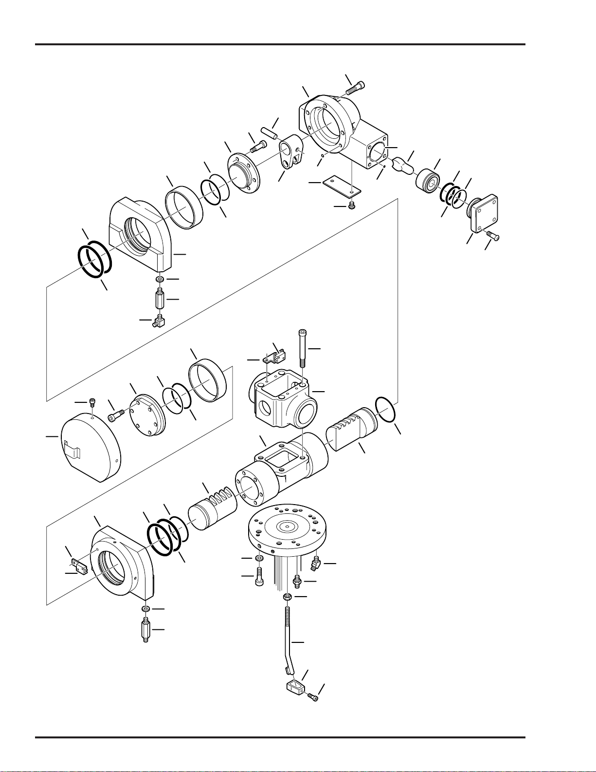
Page 14
4
2
25
25
4. TRENDELENBURG & LATERAL TILT CYLINDERS
12
13
14
16
17
18
20
15
10
11
7
9
19
21
22
23
6
8
5
4
3
4
2
1
24
20
37
38
36
18
29
28
39
27
19
6
35
19
34
34
32
19
25
30
31
25
47
46
40
41
42
22
33
43
44
45
6002.0403.00

4. TRENDELENBURG & LATERAL TILT CYLINDERS
Item Part No. Description Qty.
1 D6-010-33-1 BOLT, allen, M8 x 25 (plated) .......................................................................................8
D6-032-48 BOLT, button head, M8 x 25 .........................................................................................8
2 D2-032-69 CAP, lateral tilt, right......................................................................................................1
D2-032-70 CAP, lateral tilt, left ........................................................................................................1
3 D4-032-79 O-RING, S-55 ................................................................................................................2
4 D4-060-24 O-RING, P-49 ................................................................................................................4
5 D2-032-08-1 PISTON, lateral tilt.........................................................................................................2
6 D2-032-07-1 ROD, piston ...................................................................................................................2
7 D4-010-52 O-RING, P-4 ................................................................................................................A/R
8 D2-034-01 SLEEVE ....................................................................................................................... 2
9 D6-010-16-1 SCREW, phillips hd., M5 x 6, stainless........................................................................ 2
10 D2-032-10 PLATE, inspection cover ..............................................................................................1
D2-032-47 PLATE, inspection cover, battery model ...................................................................... 1
11 D4-010-01 O-RING, P-8 ................................................................................................................. 2
12 D6-010-45 BOLT, allen, M10 x 30.................................................................................................. 3
13 D2-032-68 HOUSING, lateral tilt .....................................................................................................1
14 D6-031-28 PIN, tapered, 12 x 55, S.N. 6002 --118 &P, 6002B -- 052 &P .......................................1
15 D2-032-12-1 LEVER, lateral tilt motion, S.N. 6002 --118 &P, 6002B -- 52 &P ...................................1
16 D6-010-30 BOLT, allen, M6 x 20 .....................................................................................................6
17 D2-032-13-1 CAP, tail, S.N. 6002 -- 118 &P, 6002B -- 052 &P ..........................................................1
-- D2-034-02 CAP, tail, S.N. 6002 -2J-119 &L, 6002B -2J-053 &L .....................................................1
18 D4-032-80 O-RING, S-70 ................................................................................................................2
19 D4-010-06 O-RING, P-60 ................................................................................................................4
20 D2-032-14 BUSHING, graphite .......................................................................................................2
21 D2-032-15 PIVOT BLOCK, lateral tilt, tail .......................................................................................1
22 D4-010-32 PACKING, copper .......................................................................................................A/R
23 D4-010-99 FITTING, plumbing ......................................................................................................A/R
24 D4-010-29 FITTING, hydraulic, 90° elbow ....................................................................................A/R
25 D4-010-07 O-RING, P-95 ................................................................................................................4
26 D2-032-20 COVER, Trendelenburg cylinder ...................................................................................1
27 D6-010-70-1 BOLT, allen, M5x10 (plated) .........................................................................................3
28 D6-010-30-1 BOLT, allen, M6 x 20 (plated) .......................................................................................6
29 D2-032-19 CAP, head, Trendelenburg cylinder .............................................................................1
30 D2-032-45 BRACKET, micro-switch ...............................................................................................2
31 D5-032-15 MICRO-SWITCH, lateral tilt ...........................................................................................2
32 D2-032-18 PIVOT BLOCK, lateral tilt, head ....................................................................................1
33 D4-010-33 FITTING, flexible hose, long........................................................................................A/R
34 D2-032-31 PISTON, Trendelenburg ................................................................................................2
35 D2-032-33 HOUSING, Trendelenburg ............................................................................................1
36 D2-032-46 BRACKET, micro-switch ...............................................................................................2
37 D5-032-16 MICRO-SWITCH, Trendelenburg ..................................................................................2
D2-032-66 ACTUATOR, micro-switch .............................................................................................1
38 D6-010-29 BOLT, allen, M10 x 85 ...................................................................................................4
39 D2-032-16 CASTING, Trendelenburg bearing ...............................................................................1
40 D4-010-30 FITTING, hydraulic, 45° elbow ....................................................................................A/R
41 D4-031-06 FITTING, flexible hose ................................................................................................A/R
42 D6-011-07 NUT, M12 ......................................................................................................................2
43 D2-032-71 BAR, hose guide ...........................................................................................................2
44 D2-010-45 HOLDER, hose ..............................................................................................................2
45 D6-011-08 BOLT, allen, M5 x 18 .....................................................................................................2
46 D6-011-06 BOLT, allen, M12 x 45 ...................................................................................................2
47 D6-010-21 WASHER, lock, M12 .....................................................................................................2
Page 15
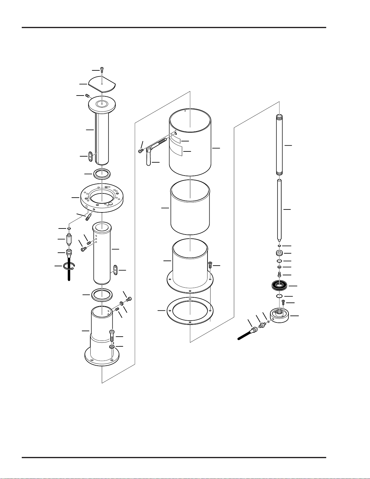
Page 16
5
7
1
5. SUPPORT COLUMN ASSEMBLY
1
2
3
4
22
5
6
44
42
43
23
28
7
10
11
2
8
24
9
13
14
15
25
5
26
17
16
29
30
31
32
33
34
3
36
38
18
27
41
40
39
3
13
19
20
21
6002.0403.005

5. SUPPORT COLUMN ASSEMBLY
Item Part No. Description Qty.
D2-010-17-1 SLIDER ASSEMBLY .....................................................................................................1
1 D6-010-28 BOLT, allen, M5x6.........................................................................................................1
2 D2-010-21 PLATE, elevation slider head ........................................................................................1
3 D6-010-27 SCREW, set, M10x15....................................................................................................2
4 D2-031-20 SLIDER, small ...............................................................................................................1
5 D2-010-16 KEY, slider.....................................................................................................................2
6 D2-010-19 STOPPER, slider, small ................................................................................................1
7 D2-031-10 RING, elevation clamp ..................................................................................................1
8 D6-010-26 STOPPER, rotation, M10x20.........................................................................................2
9 D4-010-32 PACKING, copper .......................................................................................................A/R
10 D4-010-33 FITTING, flexible hose, long..........................................................................................3
11 D4-010-21-1 HOSE, flexible, 1010mm .............................................................................................A/R
D4-010-21-3 HOSE, flexible, 980mm ...............................................................................................A/R
D4-010-21 HOSE, flexible, 1030mm ............................................................................................ A/R/
D4-010-21-6 HOSE, flexible, 1110mm .............................................................................................A/R
12 D6-010-24 TIE, cable ....................................................................................................................A/R
13 D2-010-14 BOSS, slider ..................................................................................................................2
14 D6-010-25 BOLT, allen, M8x6 .........................................................................................................2
15 D2-010-17 SLIDER, large................................................................................................................1
16 D2-010-15 STOPPER, slider, large .................................................................................................1
17 D6-010-17 BOLT, allen, M8x15 .......................................................................................................2
18 D6-010-09 WASHER, lock, M8 .......................................................................................................2
19 D2-031-08 HOLDER, slider .............................................................................................................1
20 D6-010-22 BOLT, allen, M12x35 .....................................................................................................3
21 D6-010-21 WASHER, lock, M12 .....................................................................................................3
22 D6-010-16-1 SCREW, phillips, M5x6 (stainless) ................................................................................3
23 D2-010-03-1 SHROUD, elevation, exterior, .......................................................................................1
24 D2-010-04-1 SHROUD, elevation, middle ..........................................................................................1
25 D2-031-07 SHROUD, elevation, inner.............................................................................................1
26 D6-010-19-1 SCREW, phillips, M5x10 (plated) ..................................................................................4
27 D2-010-12-1 GASKET, shroud ...........................................................................................................1
D4-031-57 ELEVATION CYLINDER ASSEMBLY ...........................................................................1
28 D2-010-06 •TUBE, elevation cylinder ..............................................................................................1
29 D2-010-07 •ROD, elevation cylinder ...............................................................................................1
30 D6-010-14 •O-RING, P-12 ...............................................................................................................1
31 D2-010-08 •PISTON, elevation cylinder (30mm) .............................................................................1
32 D4-010-12 •O-RING, P-24, (30mm piston) ......................................................................................1
33 D2-010-09 •WASHER, elevation piston ..........................................................................................1
34 D6-010-38 •BOLT, allen, M6x15 .....................................................................................................1
35 D2-010-10 •CUSHION, rubber dropping .........................................................................................1
36 D4-010-15 •O-RING, AN6227-24 (30 mm piston) ...........................................................................1
37 D2-010-11-1 •SAUCER, elevation cylinder ........................................................................................1
38 D6-010-18 BOLT, cylinder saucer mtg., M8x25 ..............................................................................2
39 D4-010-32 PACKING, copper .......................................................................................................A/R
40 D4-010-31 FITTING, flexible hose, short ........................................................................................1
41 D4-010-23 HOSE, flexible, elevation cylinder, (240mm) .................................................................1
42 D6-034-18 LABEL, top rotation handle ...........................................................................................1
43 D6-034-19 LABEL, table top warning ..............................................................................................1
44 D2-034-05 HANDLE, table top locking ............................................................................................1
Page 17

Page 18
6. ELECTRICAL COMPONENTS
1
4
42
36
41
2
3
7
6
8
9
10
11
16
19
12
32
15
13
17
20
18
5
14
35
34
33
37
31
38
21
39
22
40
44
43
47
48
45
46
23
24
25
26
27
28
29
30
28
6002.0403.006

6. ELECTRICAL COMPONENTS
Item Part No. Description Qty.
D5-031-74 PENDANT CONTROL ASSEMBLY ..............................................................................1
1 D6-010-57-1 •SCREW, pendant hook, M4 x 12 (plated) ....................................................................3
2 D5-034-07 •HOOK, pendant............................................................................................................1
3 D5-034-09 •INSERT, pendant hook ................................................................................................1
4 D5-031-22 •COVER, rubber ............................................................................................................1
5 D5-031-13-1 •STRAIN RELIEF, pendant end.....................................................................................1
6 D5-031-34 •INSERT, pendant hook ................................................................................................1
7 D5-030-23 •MICRO-SWITCH ........................................................................................................A/R
8 D5-031-21 •GASKET, micro-switch plate........................................................................................1
9 D5-031-20 •PLATE, micro-switch mounting ....................................................................................1
10 D5-031-07 •SPRING, pendant button............................................................................................A/R
11 ----- •BUTTON, pendant, (specify function & S.N.).............................................................A/R
12 D5-030-48 •CHROME RING, indicator light ....................................................................................1
13 D5-030-43 •INDICATOR LIGHT, green ...........................................................................................1
14 D6-010-109 •SCREW, M3x16 ...........................................................................................................6
15 D6-032-15 •SCREW, M3x10 ...........................................................................................................2
16 D5-031-12-1 •HOLDER, plastic button ...............................................................................................1
17 D5-030-42 •WASHER, special ........................................................................................................6
18 D6-010-10-9 •SCREW, phillips, M3x15 ..............................................................................................6
19 D5-031-75 •FACE PLATE, pendant control ....................................................................................1
20 D6-010-80-1 •SCREW, phillips, M3x6 ................................................................................................4
21 D5-031-13 •CORD, pendant control ................................................................................................1
22 D6-010-24 •TIE, cable .....................................................................................................................1
23 D5-030-18 •COVER, cannon connector ..........................................................................................1
24 D5-031-13-1 •STRAIN RELIEF, connector end ..................................................................................1
25 D5-030-21 •CONNECTOR, cannon, 19-pin, male..........................................................................1
26 D6-010-57-1 SCREW, phillips, M4x10 (plated) ..................................................................................4
27 D5-030-20 CONNECTOR, cannon, 19-pin, female ........................................................................1
28 D5-030-46 GASKET, connector ......................................................................................................2
29 D6-032-10 SCREW .........................................................................................................................4
30 D5-032-20 COVER, auxillary base connector .................................................................................1
31 D5-131-01 CONNECTOR, 8-pin, female........................................................................................2
32 D5-131-02 CONNECTOR, 8-pin, male...........................................................................................2
33 D5-030-03 CONNECTOR, 2-pin, female......................................................................................A/R
34 D5-030-02 CONNECTOR, 2-pin, male.........................................................................................A/R
35 D5-032-27 CONNECTOR, 15-pin, female (CN-20) .........................................................................1
D5-032-73 WIRE HARNESS, relay box to riser cord ......................................................................1
36 D5-032-28 CONNECTOR, 16-pin, female (CN-7) ...........................................................................1
37 D5-131-03 CONNECTOR, 16-pin, female (CN-6) ...........................................................................1
38 D5-032-10 CONNECTOR, 20-pin, female (CN-8) ..........................................................................1
39 D6-010-70 BOLT, allen, M5x10 .......................................................................................................2
40 D5-032-30 RELAY BOX ..................................................................................................................1
41 D5-032-14 CONNECTOR, 5-pin, female........................................................................................1
42 D5-030-29 CAPACITOR, motor starting..........................................................................................1
43 D6-010-19 SCREW, phillips, M 5 x 10 ............................................................................................1
44 D5-034-31 BRACKET, capacitor .....................................................................................................1
45 D5-030-05 CONNECTOR, 3-pin, female........................................................................................1
46 D5-030-04 CONNECTOR, 3-pin, male...........................................................................................1
47 D5-030-02 CONNECTOR, 2-pin, male..........................................................................................A/R
48 D5-030-03 CONNECTOR, 2-pin, female .......................................................................................A/R
-- D5-032-00 AUXILLIARY BASE CONNECTOR KIT ...................................................................... NS
Page 19

Page 20
0
13
7. ELECTRICAL COMPONENTS, BATTERY MODEL
3
1
4
6
7
8
12
2
11
14
5
15
37
38
39
34
35
36
40
18
41
33
24
42
19
32
16
20
31
17
26
23
30
22
27
21
29
28
25
53
10
9
51
71
72
73
74
75
76
77
78
79
52
54
55
65
80
81
79
56
61
57
58
59
60
66
61
62
69
7
6364
67
68
43
45
44
46
47
48
49
50
6002.0403.007

7. ELECTRICAL COMPONENTS, BATTERY MODEL
Item Part No. Description Qty.
1 D5-032-31 RELAY BOX ..................................................................................................................1
2 D5-032-14 CONNECTOR, 5-pin, female (CN-4) ............................................................................1
3 D5-032-27 CONNECTOR, 15-pin, female (CN-2) ...........................................................................1
D5-032-73 WIRE HARNESS, relay box to riser cord ......................................................................1
4 D5-131-02 CONNECTOR, 8-pin, male...........................................................................................1
5 D5-131-01 CONNECTOR, 8-pin, female........................................................................................1
6 D5-032-10 CONNECTOR, 20-pin, female (CN-1) ..........................................................................1
7 D5-131-03 CONNECTOR, 16-pin, female (CN-6) ...........................................................................1
8 D5-032-28 CONNECTOR, 16-pin, female (CN-7) ...........................................................................1
9 D5-030-02 CONNECTOR, 2-pin, male.........................................................................................A/R
10 D5-030-03 CONNECTOR, 2-pin, female......................................................................................A/R
11 D6-032-21 BOLT, allen, M5x105 .....................................................................................................2
12 D1-032-23 TRAY, relay box ............................................................................................................1
13 D1-032-21 COVER, battery .............................................................................................................1
14 D5-032-43 BATTERY, 12V..............................................................................................................2
15 D1-032-21 COVER, battery .............................................................................................................1
16 D6-032-22 BOLT, allen ...................................................................................................................2
17 D6-060-16 WASHER, lock, M4 .......................................................................................................2
18 D5-034-33 FITTING.........................................................................................................................1
19 D4-032-67 FITTING.........................................................................................................................1
20 D4-032-66 TUBE, suction ...............................................................................................................1
21 D6-010-76 NUT, M5 ........................................................................................................................4
22 D6-010-77 WASHER, lock, M5 .......................................................................................................4
23 D4-031-65 ISOLATION MOUNT, motor ..........................................................................................4
24 D5-034-32 PUMP/motor assembly ..................................................................................................1
25 D5-030-03 CONNECTOR, 2-pin, female......................................................................................A/R
26 D5-034-33 FITTING.........................................................................................................................1
27 D4-032-63 FITTING.........................................................................................................................1
28 D4-032-64 HOSE, flexible, pump return ..........................................................................................1
29 D1-032-22 STAND-OFF ..................................................................................................................2
30 D6-010-70 BOLT, allen, M5x10 .......................................................................................................2
31 D5-032-57 CHARGER, battery........................................................................................................1
D5-031-50 •TRANSFORMER..........................................................................................................1
32 D5-032-59 CONNECTOR, 6-pin, male...........................................................................................1
33 D5-032-60 CONNECTOR, 6-pin, female........................................................................................1
34 D5-032-65 CAPACITOR, charging box ..........................................................................................1
35 D6-010-19 SCREW, phillips, M 5x10 ..............................................................................................1
36 D1-031-19 BRACKET, capacitor .....................................................................................................1
37 D6-060-07 BOLT, allen, M 4x8 ........................................................................................................2
38 D5-034-49 BUZZER, battery model ................................................................................................1
39 D1-032-22 STAND-OFF ..................................................................................................................2
40 D5-030-03 CONNECTOR, 2-pin, female......................................................................................A/R
41 D5-030-02 CONNECTOR, 2-pin, male.........................................................................................A/R
42 D5-031-48 COVER, fuse holder ......................................................................................................1
43 D5-032-42 FUSE, 15amp ................................................................................................................1
44 D5-050-37 SCREW, phillips, M 4x8 ...............................................................................................1
45 D5-031-49 FUSE HOLDER .............................................................................................................1
46 D6-060-16 WASHER, lock, M4 .......................................................................................................1
47 D6-031-45 SCREW, phillips, M4x15 ...............................................................................................2
48 D5-032-51 RELAY, switch over .......................................................................................................1
Page 21

Page 22
0
13
7. ELECTRICAL COMPONENTS, BATTERY MODEL (continued)
3
1
4
6
5
7
8
12
2
11
14
15
37
38
39
34
35
36
40
18
41
33
24
42
19
32
16
20
31
17
26
23
30
22
27
29
21
28
25
53
10
9
51
71
72
73
74
75
76
77
78
79
52
54
55
65
80
81
79
56
61
57
58
59
60
66
61
62
69
7
6364
67
68
43
45
44
46
47
48
49
50
6002.0403.007

7. ELECTRICAL COMPONENTS, BATTERY MODEL (continued)
Item Part No. Description Qty.
49 D5-032-56 TERMINAL STAND, relay .............................................................................................1
50 D6-060-16 WASHER, lock, M4 .....................................................................................................A/R
D5-031-80 PENDANT CONTROL ASSEMBLY ..............................................................................1
51 D6-032-33 •SCREW, pendant hook, M4 x 12 .................................................................................3
52 D5-034-07 •HOOK, pendant ............................................................................................................1
53 D5-034-09 •INSERT, pendant hook ................................................................................................1
54 D5-031-22 •COVER, rubber ............................................................................................................1
55 D5-031-34 •INSERT, pendant hook ................................................................................................1
56 D5-030-23 •MICRO-SWITCH ........................................................................................................A/R
57 D5-031-21 •GASKET, micro-switch plate ........................................................................................1
58 D5-031-20 •PLATE, micro-switch mounting ....................................................................................1
59 D5-031-07 •SPRING, pendant button............................................................................................A/R
60 ----- •BUTTON, pendant (specify button & S.N.) ................................................................A/R
61 D5-030-48 •CHROME RING, indicator light ....................................................................................2
62 D5-030-43 •INDICATOR LIGHT, green ...........................................................................................1
63 D6-032-15 •SCREW, M3x10 ...........................................................................................................2
64 D5-030-43-1 •INDICATOR LIGHT, amber ..........................................................................................1
65 D6-010-109 •SCREW, M3x16 ...........................................................................................................6
66 D5-031-56 •HOLDER, plastic button ...............................................................................................1
67 D5-030-42 •WASHER, special ........................................................................................................6
68 D6-010-10-9 •SCREW, phillips, M3x15 ..............................................................................................6
69 D5-031-81 •FACEPLATE, pendant control .....................................................................................1
70 D6-010-80-1 •SCREW, phillips, M3x6 ................................................................................................4
71 D5-031-13-1 •STRAIN RELIEF, pendant end.....................................................................................1
72 D5-031-38 •CORD, pendant control ................................................................................................1
73 D6-010-24 •TIE, cable .....................................................................................................................1
74 D5-030-18 •COVER, cannon connector ..........................................................................................1
75 D5-031-13-2 •STRAIN RELIEF, connector end ..................................................................................1
76 D5-032-38 •CONNECTOR, cannon, 24-pin, male..........................................................................1
77 D6-010-57-1 •SCREW, phillips, M4x10 (plated) .................................................................................4
78 D5-032-39 •CONNECTOR, 24-pin, female, cannon......................................................................1
79 D5-030-46 •GASKET, connector .....................................................................................................2
80 D6-032-10 •SCREW ........................................................................................................................4
81 D5-032-20 •COVER, auxillary base connector...............................................................................1
Page 23

Page 24
6002.0403.08
7
8. HYDRAULIC VALVES & FITTINGS
54
55
85
53
51
84
82
81
83
78
52
80
79
7
1 20
2
10
12
9
16
17
4
30
11
13
14
18
15
31
19
3
21
5
6
7
7
26
22
23
24
27
29
28
10
25
8
35
34
32
33
11
37
9
41
16
17
93
87
56
92
91
89
90
88
86
52
51
42
53
54
57
58
39
40
36
65
46
47
37
35
43
38
45
44
48
49
50
56
55
16
17
66
67
68
69
71
74
75
76
70
72
73
16
61
62
63
62
64
59
60

8. HYDRAULIC VALVES & FITTINGS
Item Part No. Description Qty.
D4-031-23 PRESSURE RELIEF VALVE.........................................................................................1
1 D4-034-20 •CAP, pressure relief valve............................................................................................1
2 D4-031-67 •O-RING, P-10...............................................................................................................1
3 D6-034-14 •SCREW ........................................................................................................................3
4 D4-034-21 •BODY, pressure relief valve.........................................................................................1
5 D4-010-51 •O-RING, P-16...............................................................................................................1
6 D4-031-12 •SPRING........................................................................................................................1
7 D4-031-23-4 •VALVE, relief, 5mm dia (steel) .....................................................................................1
8 D4-031-23-2 •HOUSING, relief valve (5mm dia valve).......................................................................1
9 D6-010-76 NUT, M5 ........................................................................................................................4
10 D6-010-77 WASHER, lock, M5 .......................................................................................................4
11 D4-010-19 STUD, M5 ......................................................................................................................2
12 D6-010-64 BOLT, allen, M5x40 .......................................................................................................2
13 D4-010-40 CAP, end .......................................................................................................................1
14 D4-010-52 O-RING, P-4 ................................................................................................................A/R
15 D4-030-02 ELECTRO/MINI VALVE ASSEMBLY (4-way), 120VAC ..............................................A/R
D4-032-60 ELECTRO/MINI VALVE ASSEMBLY (4-way), 24VDC ...............................................A/R
16 D4-010-24 BOLT, plumbing, M6....................................................................................................A/R
17 D4-010-08 O-RING, P-7 ................................................................................................................A/R
18 ----- OIL LINE, specify function ...........................................................................................A/R
19 D4-031-21 ELECTRO/MINI VALVE ASSEMBLY (3-way), 120VAC, elevation .............................A/R
D4-032-92 ELECTRO/MINI VALVE ASSEMBLY (3-way), 120VAC, brake (Blue Dot) .................A/R
D4-032-59 ELECTRO/MINI VALVE ASSEMBLY (3-way), 24VDC, elevation ...............................A/R
D4-032-93 ELECTRO/MINI VALVE ASSEMBLY (3-way), 24VDC, brake (Blue Dot) ...................A/R
20 D4-010-26 BOLT, plumbing, M6 (long) .........................................................................................A/R
21 D4-032-23 TERMINAL, plumbing ....................................................................................................1
22 D6-032-13 BOLT, allen, M6 x 140 ...................................................................................................2
23 D6-010-85 WASHER, flat, M6 .........................................................................................................2
24 D6-031-16 BUSHING, isolation .......................................................................................................4
25 D4-032-81 STAND-OFF ..................................................................................................................2
26 D4-010-32 PACKING, copper .......................................................................................................A/R
27 ----- FITTING, flexible hose ................................................................................................A/R
28 ----- HOSE, flexible (specify function).................................................................................A/R
29 D4-010-18 CAP, blind, M6...............................................................................................................1
30 D6-010-65 BOLT, allen, M5 x 35 .....................................................................................................4
31 D6-031-22 BOLT, allen, M5 x 55 .....................................................................................................3
32 D6-032-03 WASHER, flat, M5 (special) ..........................................................................................3
33 D6-032-04 INSULATOR ..................................................................................................................3
34 ----- HOSE, flexible (specify function).................................................................................A/R
35 D4-030-12 FITTING, hydraulic, 90°...............................................................................................A/R
36 D4-030-05 PUMP/MOTOR ASSEMBLY .........................................................................................1
37 D4-030-03 OIL LINE, supply ...........................................................................................................1
38 D1-030-14 PAD, insulating, motor ...................................................................................................1
39 D6-131-02 RUBBER, antivibration ..................................................................................................3
40 D6-131-03 NUT, antivibration rubber ..............................................................................................3
41 D6-010-67 BOLT, allen, M5 x 15 .....................................................................................................4
42 D4-031-14 COVER, oil tank ............................................................................................................1
43 D4-031-13 GASKET, oil tank cover.................................................................................................1
44 D4-030-19 TUBE, induction ............................................................................................................1
45 D4-031-11 STRAINER, oil ...............................................................................................................1
46 D6-010-51 BOLT, allen, M6 x 10 .....................................................................................................2
Page 25

Page 26
6002.0403.08
7
8. HYDRAULIC VALVES & FITTINGS (continued)
54
55
85
53
51
84
82
81
83
78
52
80
79
7
1 20
2
10
12
9
16
17
4
30
11
13
14
18
15
31
19
3
21
5
6
7
7
26
22
23
24
27
29
28
10
25
8
35
34
32
33
11
37
9
41
16
17
93
87
56
92
91
89
90
88
86
52
51
42
53
54
57
58
39
40
36
65
46
47
37
35
43
38
45
44
48
49
50
56
55
16
17
66
67
68
69
71
74
75
76
70
72
73
16
61
62
63
62
64
59
60

8. HYDRAULIC VALVES & FITTINGS (continued)
Item Part No. Description Qty.
47 D6-010-85 WASHER, flat, M6 .........................................................................................................2
48 D4-010-39 CAP, oil filler ..................................................................................................................1
49 D4-010-38 FITTING, oil filler ...........................................................................................................1
50 D4-010-37 GASKET, oil filler...........................................................................................................1
51 D4-032-47 OIL LINE ........................................................................................................................1
52 D4-032-48 FLEXIBLE HOSE...........................................................................................................1
53 D4-032-49 OIL LINE ........................................................................................................................1
54 D4-032-50 OIL LINE ........................................................................................................................1
55 D4-032-51 FLEXIBLE TUBE ...........................................................................................................1
56 D4-032-52 OIL LINE ........................................................................................................................1
D4-032-45 EMERGENCY BRAKE RELEASE ASSEMBLY ............................................................1
57 D4-032-24-1 •BLOCK, emergency brake release ..............................................................................1
58 D4-032-46 •SPACER ......................................................................................................................1
59 D4-010-52 •O-RING, P-4 .................................................................................................................1
60 D4-032-25 •HANDLE, emergency brake release ............................................................................1
61 D6-032-41 SCREW, set ..................................................................................................................1
62 D6-010-41 NUT, M6 ........................................................................................................................2
63 D6-010-40 WASHER, M6 ................................................................................................................1
64 D6-010-30 BOLT, allen, M6 x 20 ...................................................................................................A/R
65 D4-034-22 RESERVOIR, oil tank ....................................................................................................1
66 D4-034-23 PLATE, oil tank receiving ..............................................................................................1
67 D6-010-30 BOLT, allen, M6 x 20 ...................................................................................................A/R
68 D6-031-15 WASHER, M6 ..............................................................................................................A/R
69 D1-031-12 BUSHING, isolation .......................................................................................................6
70 D4-065-01 FITTING, plumbing ......................................................................................................A/R
71 D4-035-47 CYLINDER ASSEMBLY, brake .....................................................................................4
72 D4-031-95-1 SEAT, brake rubber .......................................................................................................4
73 D4-031-96 PAD, brake, self-leveling, hard ......................................................................................2
D4-031-97 PAD, brake, self-leveling, soft .......................................................................................2
74 D6-010-39 BOLT, allen, M6 x 45 ....................................................................................................16
75 D6-010-36 WASHER .......................................................................................................................4
76 D6-010-30 BOLT, allen, M6 x 20 .....................................................................................................4
D4-017-15 EMERGENCY BRAKE RELEASE ASSEMBLY (ALTERNATE) ....................................1
77 D6-017-29 •DECAL .........................................................................................................................1
78 D6-060-38 •SCREW, set, M5 x 10 ..................................................................................................1
79 D6-017-30 •KNOB ...........................................................................................................................1
80 D6-010-87 •SCREW, set, M6 x 20 ..................................................................................................1
81 D6-017-31 •RING, retaining ............................................................................................................1
82 D6-010-41 •NUT, hex, M6 ...............................................................................................................2
83 D6-035-06 •SCREW, set, M6 x 25 ..................................................................................................2
84 D6-017-32 •SPACER ......................................................................................................................1
85 D4-017-16 •BLOCK, emergency brake release ..............................................................................1
86 D6-017-34 •PLUG, cap ....................................................................................................................2
87 D4-010-08 •O-RING, P-7 .................................................................................................................2
88 D6-017-33 •SPRING........................................................................................................................1
89 D4-017-17 •VALVE ..........................................................................................................................1
90 D4-017-18 •PILOT PLUNGER.........................................................................................................1
91 D4-010-08 •O-RING, P-7 .................................................................................................................1
92 D4-017-19 •PLUNGER ....................................................................................................................1
93 D4-041-15 •O-RING, P-18 ...............................................................................................................1
Page 27
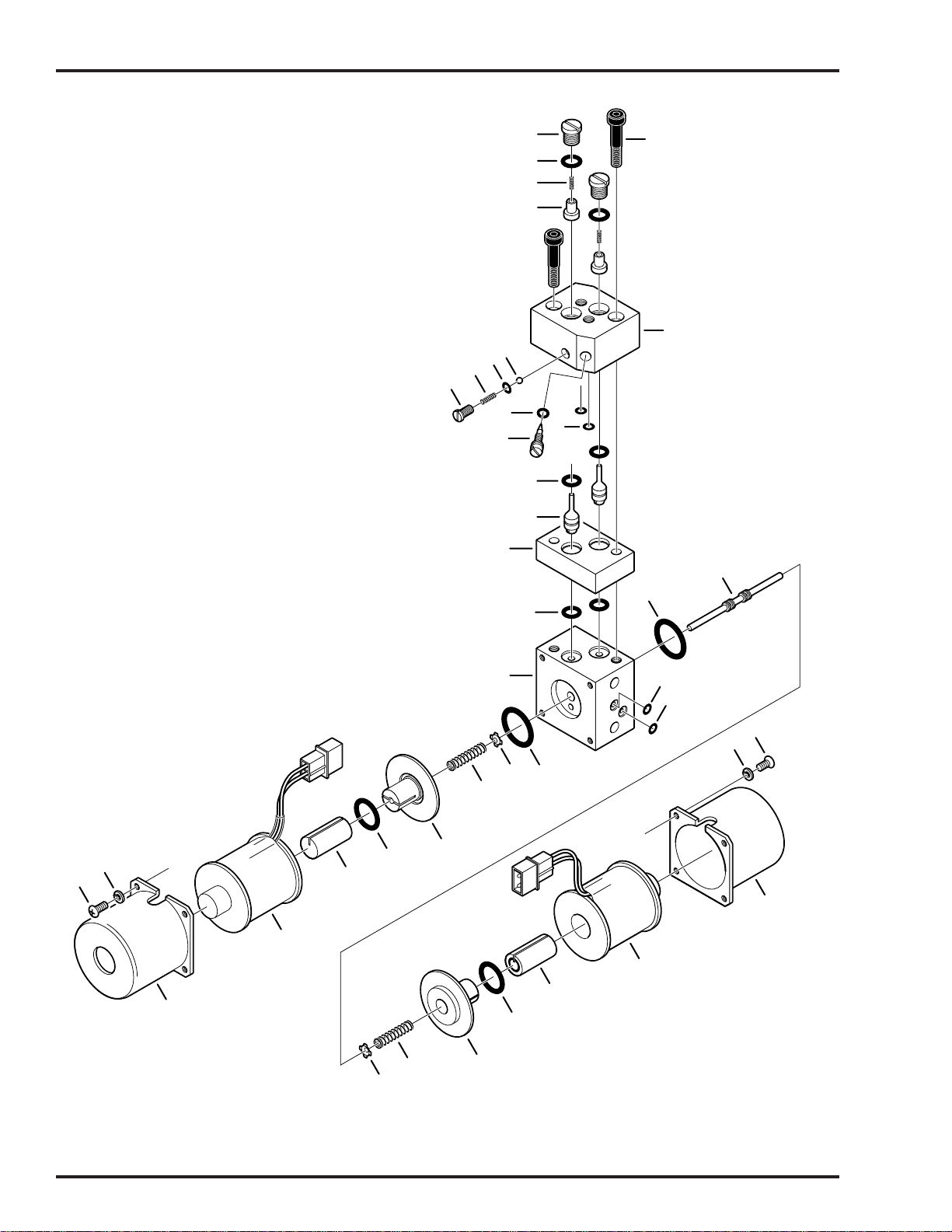
Page 28
9
2
9. ELECTRO / MINI VALVE ASSEMBLY
10
2
1
3
4
5
6
7
8
9
11
12
13
14
15
16
20
19
14
17
18
18
29
28
21
19
22
28
9
24
25
23
27
26
26
25
27
21
22
24
23
6002.0403.00

9. ELECTRO / MINI VALVE ASSEMBLY
Item Part No. Description Qty.
1 D6-010-65 BOLT, allen, M5x35 ...................................................................................................... 2
2 D4-010-41 PLUG, cap...................................................................................................................A/R
3 D4-010-08 O-RING, P-7................................................................................................................A/R
4 D4-010-42 SPRING, return ...........................................................................................................A/R
5 D4-010-25 VALVE, non-return ......................................................................................................A/R
6 D4-010-43 VALVE BLOCK, 4-way................................................................................................A/R
D4-010-23 VALVE BLOCK, 3-way ................................................................................................A/R
7 D4-034-25 BALL, check ................................................................................................................A/R
8 D4-050-12 O-RING, P-5................................................................................................................A/R
9 D4-034-26 SPRING .......................................................................................................................A/R
10 D4-034-27 PLUG...........................................................................................................................A/R
11 D4-010-20 O-RING, P-3 ................................................................................................................A/R
12 D4-010-44 VALVE, needle, speed control ....................................................................................A/R
13 D4-010-19 O-RING, P-6 ................................................................................................................A/R
14 D4-010-01 O-RING, P-8 ................................................................................................................A/R
15 ----- PILOT PLUNGER (not available separately) ..............................................................A/R
16 ----- VALVE BLOCK (not available separately) ..................................................................A/R
17 ----- VALVE BLOCK (not available separately) ..................................................................A/R
18 D4-010-52 O-RING, P-4 ................................................................................................................A/R
19 D4-010-51 O-RING, P16 ...............................................................................................................A/R
20 ----- SPOOL VALVE (not available separately) ..................................................................A/R
21 D4-034-28 RETAINER, spool valve ..............................................................................................A/R
22 D4-034-29 SPRING, return, spool valve .......................................................................................A/R
23 D4-034-30 GUIDE, bushing ..........................................................................................................A/R
24 D4-010-14 O-RING, P-12 ..............................................................................................................A/R
25 D4-034-31 PLUNGER, spool valve ...............................................................................................A/R
26 D5-030-34 SOLENOID, 120VAC ..................................................................................................A/R
D5-031-35 SOLENOID, 24VDC ....................................................................................................A/R
27 D5-034-37 HOUSING, solenoid ....................................................................................................A/R
28 D6-010-78 WASHER, lock, M3 ...................................................................................................... 8
29 D6-010-79 SCREW, phillips, M3x5 ................................................................................................8
Page 29

Page 30
8
9
10. BASE ASSEMBLY
1
2
3
11
4
6
5
6
7
8
9
25
21
22
23
24
52
10
12
51
50
13
33
49
31
32
30
14
34
35
15
36
37
38
16
17
20
19
18
26
27
39
40
41
47
48
45
46
43
42
53
56
54
55
60
61
44
57
58
59
2
2
6002.0403.010

10. BASE ASSEMBLY
Item Part No. Description Qty.
1 D6-035-04 SCREW, phillips, M4x8, button head ............................................................................4
2 D5-034-38 FACEPLATE, switch, 6 switch ......................................................................................1
3 D5-034-39 COVER, switch assembly .............................................................................................1
4 D5-034-40 SWITCH PLATE ASSEMBLY........................................................................................1
-- D5-034-41 •SWITCH, toggle, 2 position ..........................................................................................6
5 D1-131-01 COVER, service access (6002B model) .......................................................................1
D1-131-02 COVER, service access (6002 model) ..........................................................................1
6 D6-035-08 SCREW, phillips, M4 x 8, flat head ...............................................................................5
7 D1-031-37 FRAME ..........................................................................................................................1
8 D1-032-10 GASKET ........................................................................................................................1
9 D1-032-11 HOUSING, base ............................................................................................................1
10 D6-031-29 DECAL, grounding reliability .........................................................................................1
11 D6-032-08 SCREW, allen, M4 x 6 (black) .......................................................................................4
12 D1-032-13 PLATE, fuse cover, (6002B model) ...............................................................................1
D1-032-12 PLATE, fuse cover, (6002 model) .................................................................................1
13 D5-031-53 LIGHT, indicator, (6002B model) ...................................................................................1
14 D6-010-67 BOLT, allen, M5 x 15 ....................................................................................................10
15 D6-031-30 DECAL, caution, electric shock .....................................................................................1
16 D6-010-51 BOLT, allen, M6 x 10 .....................................................................................................2
17 D6-010-85 WASHER, flat, M6 .........................................................................................................2
18 D6-031-43 DECAL, danger, explosion hazard 1 .............................................................................1
19 D6-011-32 DECAL, danger, explosion hazard 2 .............................................................................1
20 D6-011-34 DECAL, radiation performance standard 21CFR ..........................................................1
21 D6-031-56 DECAL, emergency brake release ................................................................................1
22 D1-032-16 COVER, transformer .....................................................................................................1
23 D6-050-36 BOLT, allen, M5 x 8 .......................................................................................................2
24 D6-032-17 SCREW, phillips ............................................................................................................2
25 D5-032-58 TRANSFORMER, battery charger.................................................................................1
26 D6-032-18 BOLT, allen ...................................................................................................................2
27 D1-032-17 PLATE, transformer mounting .......................................................................................1
28 D1-010-30 CASTER. 105H-P ..........................................................................................................4
29 D6-010-96 BOLT, allen, M10 x 20 ..................................................................................................16
30 D6-032-06 BOLT, allen, M4 x 20 .....................................................................................................2
31 D5-032-37 RETAINER, power cord.................................................................................................1
32 D6-010-16 SCREW, phillips, M5 x 6 ...............................................................................................1
33 ----- WIRE, ground ..............................................................................................................A/R
34 D6-032-06 BOLT, allen, M4 x 20 .....................................................................................................1
35 D6-010-59 NUT, M4 ........................................................................................................................1
36 D6-010-30 BOLT, allen, M6 x 20 .....................................................................................................2
37 D6-010-41 NUT, M6 ........................................................................................................................2
38 D5-032-55 SWITCH, main power ....................................................................................................1
39 D6-010-51 BOLT, allen, M6 x 10 .....................................................................................................3
40 D6-010-40 WASHER, lock, M6 .......................................................................................................3
41 D5-032-52-3 BRACKET, on/off switch ...............................................................................................1
42 D6-032-09 BOLT, allen, M5 x 50 .....................................................................................................1
43 D6-032-12 SPRING, (#89) ..............................................................................................................1
44 D5-032-53-1 SWITCH PEDAL, on/off switch......................................................................................1
45 D5-032-54 COVER, switch pedal ....................................................................................................1
46 D6-010-76 NUT, M5 ........................................................................................................................1
Page 31
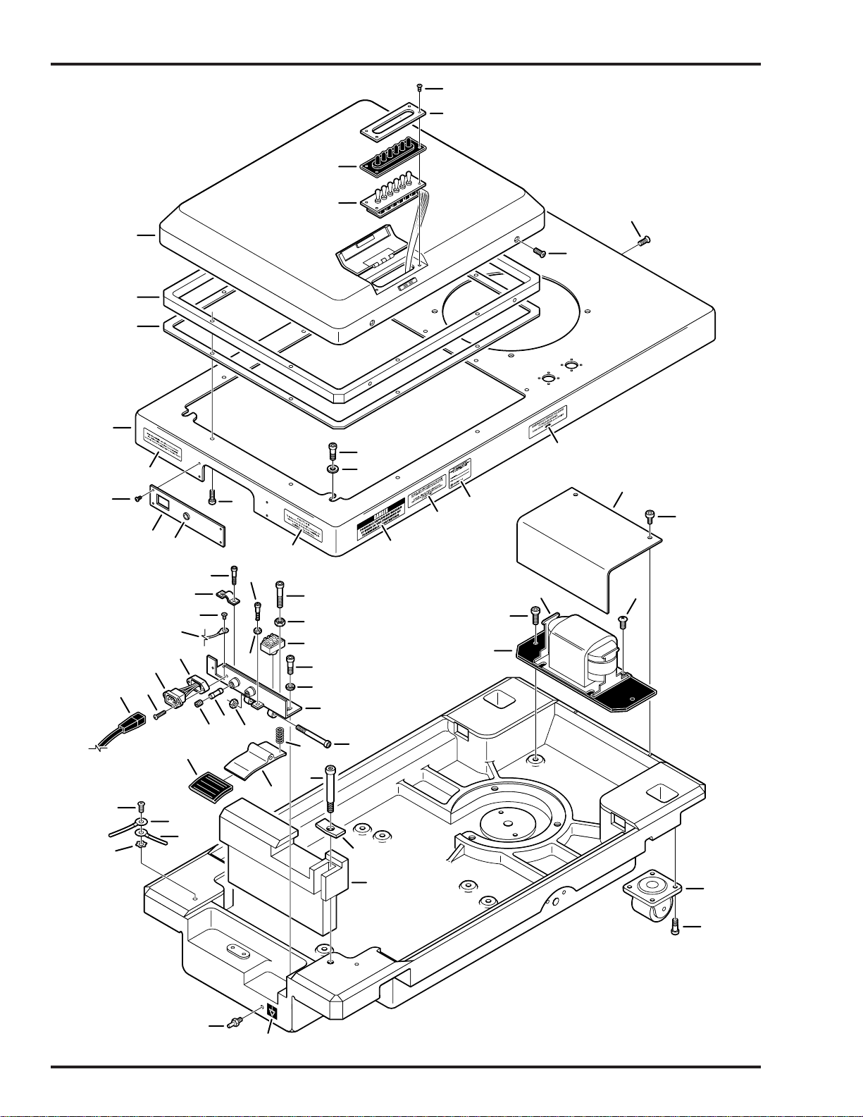
Page 32
8
9
10. BASE ASSEMBLY (continued)
1
2
3
11
4
6
5
6
7
8
9
25
21
22
23
24
52
10
12
51
50
13
33
49
31
32
30
14
34
35
15
36
37
38
16
17
20
19
18
26
27
39
40
41
47
48
45
46
43
42
53
56
54
55
60
61
44
57
58
59
2
2
6002.0403.010

10. BASE ASSEMBLY (continued)
Item Part No. Description Qty.
47 D5-032-41 FUSE, 10A.....................................................................................................................2
48 D5-032-74 FUSE HOLDER, 250V, 15A ..........................................................................................2
49 D5-031-54-2 SPACER, power cord connector ...................................................................................1
50 D5-031-54-1 CONNECTOR, power cord ............................................................................................1
51 D6-032-10 SCREW, M3 x 20 ..........................................................................................................2
52 D5-031-08 POWER CORD ASSEMBLY .........................................................................................1
53 D6-010-16-1 SCREW, phillips, M5 x 6 (plated) ..................................................................................1
54 ----- WIRE, ground ..............................................................................................................A/R
55 ----- WIRE, ground ..............................................................................................................A/R
56 D6-034-16 WASHER, star, M5 ........................................................................................................1
57 D6-031-14-1 BOLT, allen, M8 x 55 .....................................................................................................1
58 D6-034-15 BRACING ......................................................................................................................1
59 D1-034-06 BALANCE WEIGHT ......................................................................................................1
60 D6-034-20 EQUALIZATION TERMINAL .........................................................................................1
61 D6-034-21 LABEL, equalization terminal ........................................................................................1
Page 33

Page 34
Item Part No. Description Qty.
6-050-02 GAUGE, oil pressure...................................................................................................A/R
D6-010-89 GREASE, slider .........................................................................................................2.8 oz
D6-010-90 OIL, hydraulic ...............................................................................................................Qt
D4-011-02 HOSE, hydraulic, specify length..................................................................................A/R
D4-011-03 FITTING, hydraulic hose end ......................................................................................A/R
SPECIAL TOOLS & MAINTENANCE ITEMS

Page 36
5000 36th Street S.E. • Grand Rapids, MI 49512
1.800.SKYTRON • 1.616.957.0500 • FAX 1.616.957.5053

ELITE SERIES SURGICAL TABLES
MAINTENANCE MANUAL
REV 8/05
MODEL ELITE 6002
INCLUDING BATTERY MODELS
Page 59

Table of Contents
SECTION I HYDRAULIC SYSTEM ...................................................................................................... 1
1-1. General........................................................................................................................................... 1
1-2. Component Operation .................................................................................................................... 2
a. Motor/Pump Operation ............................................................................................................. 2
b. Pressure Relief Valve .............................................................................................................. 2
c. Mini-Valves............................................................................................................................... 3
d. Mini-valve in Neutral Position ................................................................................................... 3
e. Mini-Valve Right Port Activated................................................................................................ 4
f. Mini-Valve Left Port Activated .................................................................................................. 4
g. Hydraulic Cylinders (Slave Cylinders) ..................................................................................... 5
h. Elevation Cylinder Return Circuit ............................................................................................. 6
i. Brake System ........................................................................................................................... 7
j. Emergency Brake Release ...................................................................................................... 8
k. Flex/Reflex System ................................................................................................................... 8
1-3. Hydraulic Adjustments ................................................................................................................... 9
a. Fluid Level. ............................................................................................................................... 9
b. Bleeding The Hydraulic System ............................................................................................... 9
c. Pressure Relief Valve .............................................................................................................. 9
d. Speed Controls......................................................................................................................... 9
SECTION II MECHANICAL TABLE ADJUSTMENTS........................................................................ 11
2-1. Back Section Gear Mesh Adjustment ........................................................................................... 1 1
2-2. Hydraulic Cylinder Adjustment ...................................................................................................... 11
a. Back Section ........................................................................................................................... 11
b. Leg Section ............................................................................................................................. 11
SECTION III HYDRAULIC TROUBLESHOOTING ............................................................................. 12
3-1. Precautions ................................................................................................................................... 12
3-2. Troubleshooting Notes .................................................................................................................. 12
3-3. ELEVATION DIAGNOSIS CHART .............................................................................................. 13
3-4. TRENDELENBURG DIAGNOSIS CHART.................................................................................. 14
3-5. LATERAL - TILT DIAGNOSIS CHART ........................................................................................ 15
3-6. FLEX SYSTEM DIAGNOSIS CHART.......................................................................................... 16
3-7. BACK SECTION DIAGNOSIS CHART ....................................................................................... 17
3-8. LEG SECTION DIAGNOSIS CHART .......................................................................................... 18
3-9. BRAKE CIRCUIT DIAGNOSIS CHART ..................................................................................... 19
3-10. Flexible Hose Identification and Placement................................................................................... 20
REV 8/05
Although current at time of publication, SKYTRON's policy of continuous development makes this manual
subject to change without notice.
Page 53

Table of Contents (continued)
SECTION IV ELECTRICAL SYSTEM.................................................................................................. 22
4-1. General.......................................................................................................................................... 22
4-2. Components.................................................................................................................................. 22
4-3. Battery Model Components........................................................................................................... 22
SECTION V ELECTRICAL SYSTEM TROUBLESHOOTING ............................................................. 23
5-1. Troubleshooting Notes .................................................................................................................. 23
5-2. Main Switch................................................................................................................................... 23
5-3. Pendant Control ............................................................................................................................ 24
5-4. Relay Box...................................................................................................................................... 25
5-5. Solenoids....................................................................................................................................... 27
5-6. Motor/Pump Assembly .................................................................................................................. 29
5-7. Return To Level Micro-Switches................................................................................................... 31
5-8. Troubleshooting............................................................................................................................. 31
SECTION VI -6002B- BATTERY MODEL, ELECTRICAL TROUBLESHOOTING .............................. 36
6-1. General.......................................................................................................................................... 36
6-2. Troubleshooting Notes .................................................................................................................. 36
6-3. Main Switch................................................................................................................................... 37
6-4. Batteries ........................................................................................................................................ 37
6-5. Battery Charging Box/AC120V Transformer................................................................................. 38
6-6. Switch-Over Relay ........................................................................................................................ 39
6-7. Pendant Control ............................................................................................................................ 40
6-8. Auxiliary Switches......................................................................................................................... 42
6-9. Relay Box...................................................................................................................................... 43
6-10.Main Wire Harness Continuity Tests............................................................................................. 45
6-11. Solenoids....................................................................................................................................... 46
6-12. Motor/Pump Assembly.................................................................................................................. 47
SECTION VII ELECTRICAL SYSTEM ADJUSTMENTS .................................................................... 48
7-1. Relay Box Adjustments Models 6002 & 6002B............................................................................ 48
WARNING
Indicates a possibility of personal injury.
CAUTION
Indicates a possibility of damage to
equipment.
Page 54
Indicates important facts or helpful hints.
NOTE

BASIC RECOMMENDED TOOLS:
1/8". 1/4" STRAIGHT BLADE SCREWDRIVERS
#2 PHILLIPS SCREWDRIVER
HYDRAULIC PRESSURE GAUGE SKYTRON P.N. 6-050-02
METRIC ALLEN® WRENCHES 1.5mm-8mm
ADJUSTABLE CRESCENT WRENCH
DIGITAL VOLTMETER, TRUE RMS
METRIC OPEN END WRENCHES 7mm-18mm
LEVEL (CARPENTERS)
BASIC RECOMMENDED MAINTENANCE PROCEDURES
The basic items notes below should be inspected at a minimal interval period of 6 months (dependant on
usage). For optimal usage, safety and longevity of the product, have it serviced only by an authorized
Skytron representative with authentic Skytron replacement parts.
• Check Power Cord (if applicable) • Inspect Articulating Joints
• Check Pendant Control (if applicable) • Inspect Table Tops
• Check Oil Level in Reservoir • Check Operational Times and Pressure Values
• Check For Hydraulic Leaks • Check Pressure Relief Valve Setting
• Check All Table Functions • Check Side Rails
• Check Velcro • Check Lateral Tilt Housing Bolts
• Inspect Leg and Head Section detachment mechanisms for proper operation
• Lubricate Elevation Slider Assembly with SKYTRON Slider Grease P/N D6-010-89
• Tighten X-Ray Top Stand-Offs, Use Loc-tite
• Lubricate Casters
• Check brake pads for wear and inspect brake cylinders for proper operation.
Only facility-authorized SKYTRON trained, maintenance personnel should troubleshoot the
SKYTRON 6002 Surgical Table. Trouble shooting by unauthorized personnel could result in
personal injury or equipment damage.
How to contact us:
Skytron
5000 36th St. SE, Grand Rapids, MI 49512
PH: 1-800-759-8766 (SKY-TRON)
FAX: 616-957-5053
Page 55
TYPE B
EQUIPMENT
EQUIPMENT LABELS AND SPECIFICATIONS
INDICATES DANGEROUS VOLTAGE, 120 V, 60 Hz
CLASS I DEFIBRILLATION PROOF, TYPE B EQUIPMENT- IPX4 RATED.
INTERNALLY POWERED EQUIPMENT
PROTECTIVE GROUNDING.
IN ORDER TO ENSURE PROPER GROUNDING RELIABILITY,
THIS TABLE MUST BE CONNECTED TO A PROPERLY GROUNDED
HOSPITAL GRADE OUTLET.
N
10A
IPX4
V
A
HZ
CONNECTION FOR NEUTRAL CONDUCTOR SUPPLIED
UNIT TO BE USED ONLY IN SPECIFIED ENVIRONMENTAL CONDITIONS
TEMPERATURE: 15˚ - 30˚ C (60˚ -85˚ F)
HUMIDITY: 30% - 60% RELATIVE HUMIDITY, NON CONDENSING
AC VOLTAGE
FUSE (2) 10 AMP FAST ACTING
ENCLOSURE CLASS
VOLTAGE RATING OF THE UNIT
AMPERAGE RATING OF THE UNIT
FREQUENCY OF THE UNIT
ATTENTION, CONSULT MANUAL FOR FURTHER INSTRUCTIONS.
INDICATES SPECIAL USER ATTENTION.
BATTERY TYPE:
Page 56
FUSE:
POWERED BY AC VOLTAGE
BATTERY MODELS
POWERED BY BATTERY
SEALED
LEAD ACID 12V, VALVE REGULATED
16AH, 10HR (530W/10MIN)
15 AMP FAST ACTING INTERNAL FUSE
15A

.
.
6002 Series General Purpose Surgical Table Specifications
15"
10"
19-1/2"
21-1/2" 24"
60˚
90˚
13"
75"
TOP VIEW
76"
5-3/4"
8"
35-1/2"
3"
5-3/4"
SIDE VIEW
20"
22"
43" MAX
28" MIN
19"
END VIEW
Electrical Specifications
Power requirements
Current Leakage
®
Power Cord
15 feet w/hospital grade connector
120 VAC, 60Hz, 300 Watts
Less than 100 micro amps
(removeable on battery model)
Page 57
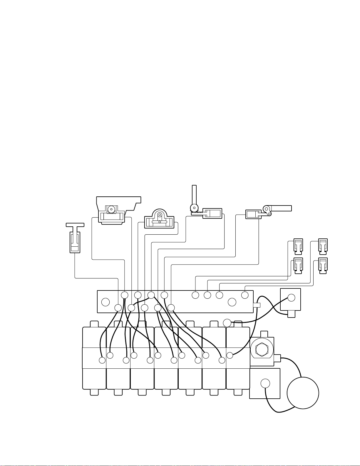
M
E
1-1. General
Electro-Hydraulic System
SECTION I HYDRAULIC SYSTEM
The hydraulic system (with the exception of the
hydraulic cylinders and hoses) is contained within
the base of the table. The hydraulic valves and
pump are electrically controlled by the use of a
hand-held push button pendant control. The power
requirements for the table are 120 VAC, 5 amp, 60
Hz.
The table contains the following components. Refer to the block diagram (figure 1-1) for relationship.
a. Oil Reservoir - Main oil supply. Approximately
two quarts.
b. Motor/Pump Assembly - A positive displacement gear type pump provides the necessary oil
pressure and volume.
TRENDELENBURG
LA TERAL TIL T
LEVATION
CYLINDER
c. Pressure Relief Valve - Provides an alternate oil
path when the hydraulic cylinders reach the end of
their stroke.
d. Electro/Hydraulic Mini-Valve Assemblies -These
direct the fluid to the appropriate hydraulic cylinders.
e. Hydraulic Lines, Fittings, Connections - They
provide a path for the hydraulic oil.
f. Hydraulic Cylinders - They convert the hydraulic
fluid pressure and volume into mechanical motion.
BACK
SECTION
LEG SECTION
BRAKE SYSTE
PLUMBING
TERMINAL
EMERGENCY
MINI-VALVES
ELEV TREND TILT FLEX BACK LEG BRAKE
OIL
RESERVOIR
BRAKE RELEASE
PRESSURE
RELIEF V AL VE
MOTOR/PUMP
ASSEMBLY
Figure 1-1. Hydraulic Block Diagram Model 6002
Page 1
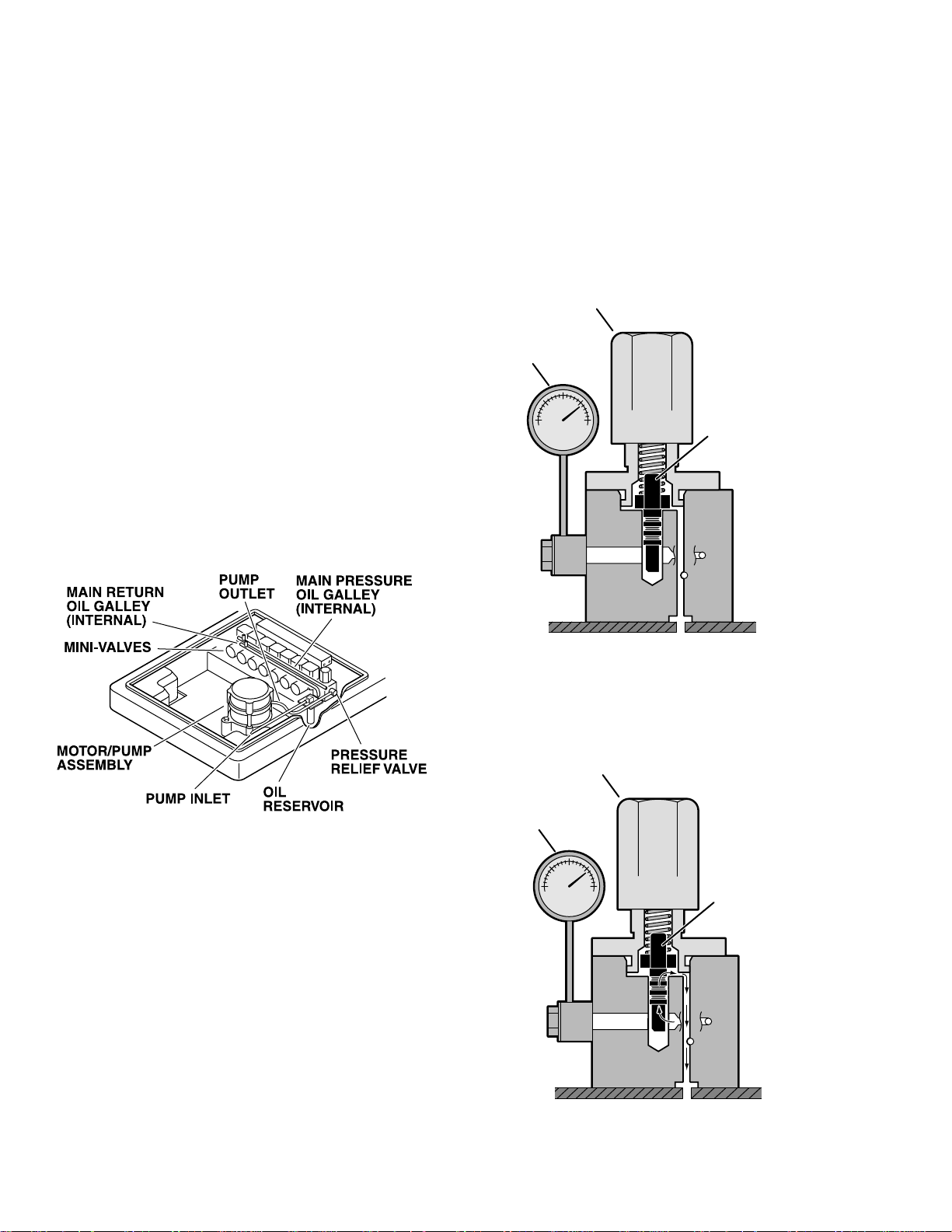
1-2. Component Operation
D
P
G
D
P
G
a. Motor/Pump Operation
The motor/pump assembly is a gear type pump
that provides the oil pressure and volume for the
entire hydraulic system. The pump has an inlet
side and an outlet side. The inlet side is connected
to the reservoir which provides the oil supply. The
reservoir has a very fine mesh screen strainer
which prevents foreign material from entering the
oil system.
The output line of the pump is connected to the main
oil galley which is internal and common to all the
hydraulic mini-valves and pressure relief valve.
Also, common to the hydraulic mini-valves and
pressure relief valve is an oil galley that internally
connects to the oil reservoir to provide a return path
for the hydraulic oil. See figure 1-2.
b. Pressure Relief Valve
The main component of the valve is an adjustable
spring loaded plunger that is pushed off from its
seat by the oil pressure. The oil then flows back into
the reservoir. See figure 1-4 Turning the adjustment nut clockwise increases the amount of oil
pressure required to open the valve, and turning it
counterclockwise decreases the amount of oil pressure. (See adjustment section for specification.)
PRESSURE RELIEF
ADJUSTMENT NUT
RESSURE
AUGE
SPRING LOADE
PLUNGER
Figure 1-3. Pressure Relief Valve Not
Functioning
PRESSURE RELIEF
ADJUSTMENT NUT
RESSURE
AUGE
Figure 1-2.
SPRING LOADE
PLUNGER
This device provides an alternate oil path when the
hydraulic cylinders reach the end of their stroke
and the pump continues to run. If this path were not
provided, the pump motor would stall because the
oil cannot be compressed. The pressure relief
valve is directly connected to the mini-valve bodies
and shares both the common internal main pressure oil galley, and the return oil galley, that internally connect to the reservoir. See figure 1-3.
Page 2
Figure 1-4 . Pressure Relief Valve
Functioning
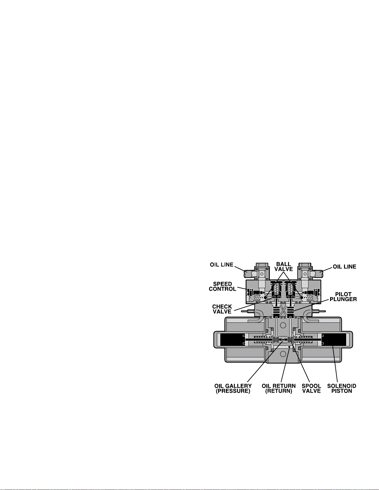
c. Mini-Valves
The operation of the mini-valves is identical for all
table functions except the elevation and Single
Action Brake circuits. These two hydraulic circuits
use a 3-way (single check valve) type mini-valve.
All other functions use a 4-way (dual check valve)
type mini-valve.
Either type mini-valve is controlled by two pushing
type, electrically operated solenoids. The solenoids push the spool valve (located in the lower
portion of the valve) one way or the other. This
motion opens the main supply galley (which has
pump pressure) allowing the oil to flow through the
various parts of the mini-valve to the function. The
spool valve also opens an oil return circuit which
allows the oil to return to the oil reservoir.
The main components of the mini-valve and their
functions are listed below:
1. Spool Valve - Opens the main oil galley
(pump pressure) to either mini-valve outlet depending on which direction the spool valve is
pushed. Also it provides a return path for the oil
returning back into the reservoir.
Also, by using this control method, it doesn’t matter
what size cylinder and piston is used because the
speed can be controlled by restricting the return oil.
If the pump puts out more volume to a certain slave
cylinder than the speed control is allowing to go
back to the reservoir, the pressure relief valve
provides an alternate path for the pump oil.
d. Mini-Valve in Neutral Position
(No fluid flow) See figure 1-5.
1. Spool Valve Centered - This closes off both
oil pressure and oil return galleys.
2. Pilot Plungers Both Closed -The pilot plungers control the opening of the check valves. If they
are closed, the check valves must be closed.
3. Check Valves - Both check valves are
closed trapping the oil in the cylinder and oil lines.
4. Speed Adjustment - When the mini-valve is
in the neutral position, the speed adjustment does
not affect anything because there is not any oil flow.
2. Pilot Plunger - There are two plungers in a
four-way mini-valve (one in a 3-way mini-valve),
one under each check valve. The purpose of the
pilot plungers is to mechanically open the return
check valve allowing the oil to return back into the
reservoir.
3. Check Valve - Two are provided in each fourway mini-valve to seal the oil in the cylinders and oil
lines and prevent any movement of the table. One
check valve is provided in a 3-way mini-valve.
4. Speed Adjustments - There are two speed
adjustments in each mini-valve. They are needle
valve type controls which restrict the volume of oil
returning back into the reservoir, thereby controlling the speed of the table surface movement. A 3way mini-valve has only one speed adjustment.
The speed controls are always located in the return
oil circuit. This prevents uncontrolled movement of
the piston in the slave cylinder due to one side of
the piston being loaded with hydraulic pressure
and the other side having no load.
Figure 1-5. Mini-Valve in Neutral Position
Page 3
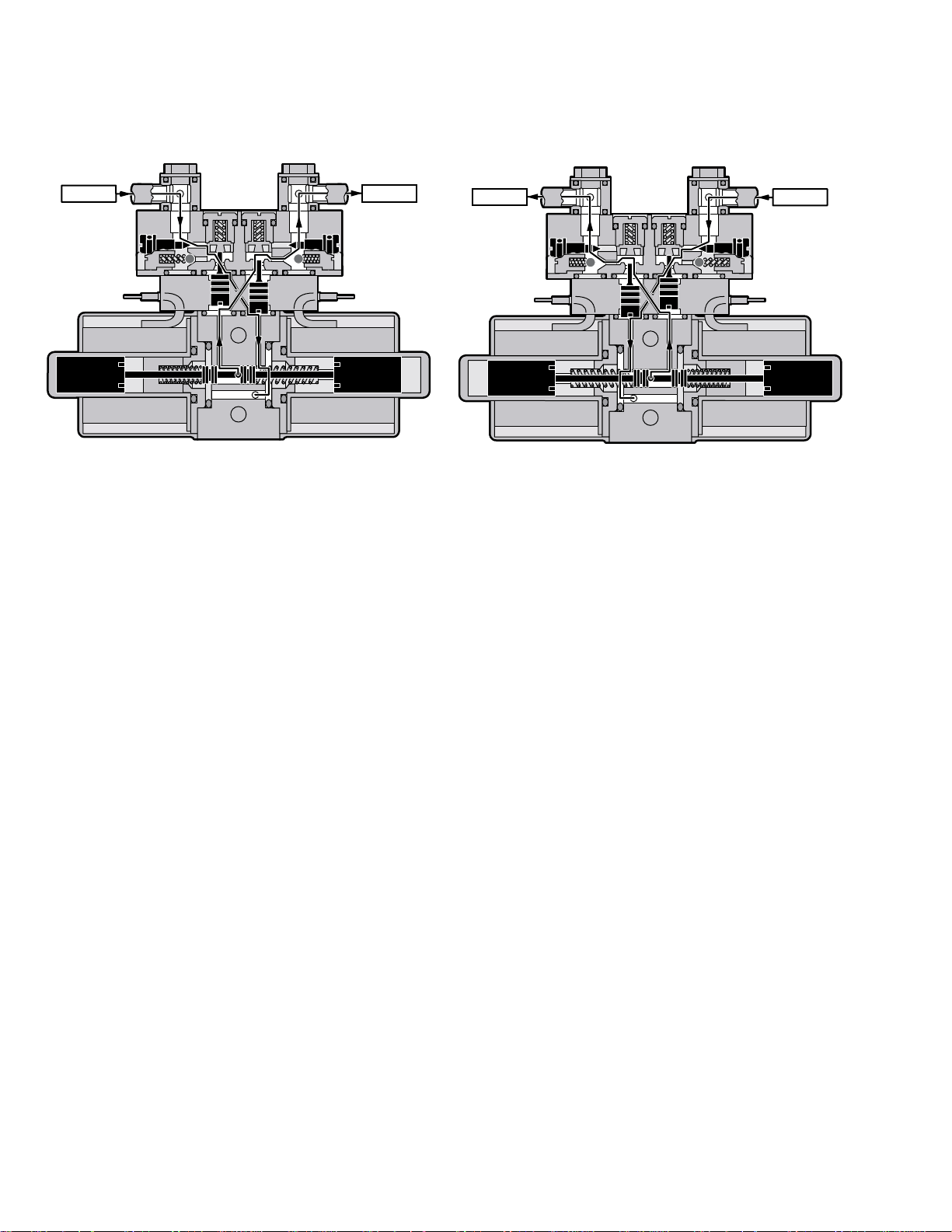
e. Mini-Valve Right Port Activated
(See figure 1-6)
Slave Cylinder Piston Moves to Left
Right Mini-Valve Port is Supply Line
Left Mini-Valve Port is Return Line
f. Mini-Valve Left Port Activated
(See figure 1-7.)
Slave Cylinder Piston Moves to Right
Left Mini-Valve Port is Supply Line
Right Mini-Valve Port is Return Line
INLET OUTLET
Figure 1-6. Mini-Valve Right Port Activated
1. Spool Valve - Pushed to the left by electric
solenoid. This opens the internal oil pressure galley allowing the fluid to go through the check valve
and on to the cylinder. Also, the spool valve opens
the oil return line providing an oil path through the
internal oil galley back to the reservoir.
OUTLET
INLET
Figure 1-7. Mini-Valve Left Port Activated
1. Spool Valve -Pushed to the right by electric
solenoid. This opens the internal oil pressure galley allowing the fluid to go through the check valve
and on to the cylinder. Also, the spool valve opens
the oil return line providing an oil path through the
internal oil galley back to the reservoir.
2. Pilot Plunger Valve - Left pilot plunger valve
is pushed up by the incoming oil pressure mechanically opening the check valve located above it in
the return circuit. This action allows the oil from the
left side of the slave cylinder to go back into the
reservoir. The right pilot plunger valve is not
affected in this operation mode.
3. Check Valves - Both check valves are
opened in this operation mode. The right check
valve is pushed open by the oil pressure created by
the pump. The oil then continues to go through the
lines and pushes the slave cylinder piston to the
left. At the same time, the left check valve is held
open mechanically by the pilot plunger providing a
return path for the oil through the mini-valve back
to the reservoir.
4. Speed Adjustment - The right speed control
(output side) does not have any effect in this
operation mode because the oil is routed around
the speed adjustment through a by-pass valve and
then to the output port. The left speed adjustment
controls the speed of the table function by restricting the amount of oil going back into the reservoir.
2. Pilot Plunger Valve - Right pilot plunger valve
is pushed up by the incoming oil pressure mechanically opening the check valve located above it in
the return circuit. This action allows the oil from the
right side of the slave cylinder to go back into the
reservoir. The left pilot plunger valve is not affected
in this operation mode.
3. Check Valves - Both check valves are
opened in this operation mode. The left valve is
pushed open by the oil pressure created by the
pump. The oil then continues to go through the
lines and pushes the slave cylinder piston to the
right. At the same time, the right check valve is held
open mechanically by the pilot plunger providing a
return path for the oil through the mini-valve back
to the reservoir.
4. Speed Adjustment - The left speed control
(output side) does not have any effect in this operation mode because the oil is routed around the
speed adjustment through a by-pass valve and
then to the output port. The right speed adjustment
controls the speed of the table function by restricting the amount of oil going back to the reservoir.
Page 4

N
E
C
g. Hydraulic Cylinders (Slave Cylinders)
RAM
HYDRAULIC LINE
PISTON
O-RING
O-RING
R
S
There are several different types of hydraulic cylinders used in the table that activate the control
functions. With the exception of the elevation and
brake cylinders, all operate basically the same
way. The control functions are listed below: (See
figure 1-8.).
Back Section--2, double action cylinders
Leg Section--2, double action cylinders
Trendelenburg--1, double action cylinder
Lateral Tilt--1, double action cylinder
Elevation--1, single action cylinder
Brakes--4, single action cylinders
TRENDELENBURG
CYLINDER
BACK SECTIO
CYLINDER
Figure 1-9. Back Section Cylinder
2. Trendelenburg Cylinder Assembly - This
cylinder / piston arrangement has rack teeth cut
into the top of each piston. These teeth mesh with
a pinon gear that is connected directly to the table
side frames. The pinion gear shaft and table side
frames are supported by bearings at either side.
When hydraulic fluid is pumped into one side of the
cylinder, the pistons are pushed in one direction,
moving the pinion gear and table side frames with
them. Oil pressure can be applied to either side of
the piston, making the table tilt end for end. See
figure 1-10.
LEG SECTION
LEVATION
YLINDER
CYLINDER
LA TERAL TIL T
CYLINDER
T ABLE TOP
PINION GEA
PISTON
SIDE VIEW
Figure 1-10. Trendelenburg Cylinder Assy.
Figure 1-8. Cylinder Placement
1. Back Section and Leg Section Cylinders The double action cylinders are closed at one end
and have a movable piston with hydraulic fluid on
both sides. Connected to this piston is a ram or
shaft that exits out of the other end of the cylinder.
Through the use of either a gear, or clevis and pin
In order to remove any looseness or play in the
table top, the trendelenburg pistons are made in
two pieces as shown in figure 1-11. This arrangement eliminates any gear lash between the piston
teeth and the table pinion gear due to oil pressure
always being present on both sides of the pistons.
OIL PRESSURE
OIL PRESSURE
arrangement, this ram is connected to a movable
table surface.
The movable surface can be moved one way or
the other by pumping hydraulic fluid into the cylinder on either side of the piston. Obviously, if oil is
pumped into one side of the cylinder, a return path
must be provided for the oil on the other side. See
figure 1-9.
Figure 1-11. Trendelenburg Cylinder Pistons
SPLIT PISTONS
REMOVE GEAR LASH
TOP VIEW
Page 5

3. Lateral Tilt Assembly - The lateral tilt assem-
P
T
O
B
P
N
bly consists of two cylinders, pistons and connecting rods. The connecting rods attach to the lateral
tilt lever which connects to the table side frames.
When hydraulic fluid is pumped into one cylinder,
the piston and connecting rod pushes the lateral tilt
lever which tilts the table top to one side. To tilt the
table top in the opposite direction, fluid is pumped
into the opposite cylinder. See figure 1-12.
T ABLE TOP
LA TERAL TIL
LEVER
5. Brake Cylinders - The brake cylinders are
single action type similar to the elevation cylinder.
The movable piston's ram is connected to a brake
pad. See figure 1-14. Oil pumped into the top of the
cylinder pushes the piston down raising the table
base off its casters. An internal return spring on the
bottom of the piston, pushes the piston up to return
the oil through the mini-valve to the reservoir.
PISTON
IL LINE
RETUR
SPRING
ISTON PISTON
Figure 1-12. Lateral Tilt Cylinder Assembly
CONNECTING
RODS
RAKE
AD
RAM
4. Elevation Cylinder - This single action cylinder does not have hydraulic fluid on both sides of
the piston. It depends on the weight of the table top
assembly to lower it.
The cylinder is set in the center of the elevation
main column. The cylinder is elevated by the driven
force of the oil pressure. When lowering, the oil that
Figure 1-14. Single Action Brake Cylinder
is accumulated in the cylinder is returned to the oil
reservoir through the mini-valve due to the table top
weight.
A slider support assembly is used to support the
h. Elevation Cylinder Return Circuit
weight of the upper table section. A stainless steel
shroud covers the flexible hydraulic hoses and
slider. See figure 1-13.
Three-way (single check valve type) mini-valves
control both the elevation and return circuits. The
elevation circuit operation within the mini-valve is
identical to the operation of the four-way valves
previously described (inlet pressure opens the
check valve allowing the oil to enter the cylinder).
In the return position, inlet pressure pushes the
pilot plunger up and opens the return check valve.
See figure 1-15. The open check valve allows a
path for the oil in the elevation cylinder to return to
the reservoir. When the pilot plunger valve is
opened, the continuing pump pressure opens the
pressure relief valve which provides a return oil
path to the reservoir.
Figure 1-13. Elevation Cylinder Assembly
Page 6
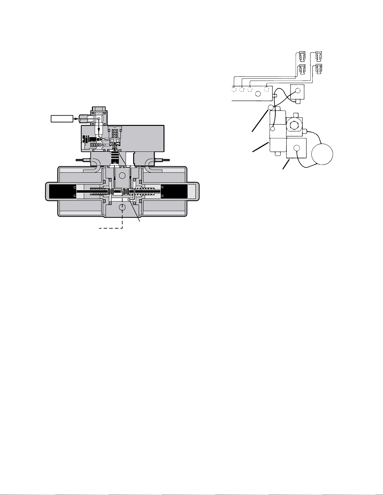
The mini-valve used in the elevation circuit con-
E
R
R
tains only one check valve (all four-way minivalves use two check valves). The check valve is
used to trap the oil in the elevation cylinder thereby
supporting the table top. When the top is being
lowered the check valve is mechanically held open
by the pilot plunger through pump pressure.
INLET
PLUMBING
TERMINAL
ETURN TO
ESERVOIR
BRAKE
BRAKE SYSTEM
EMERGENCY
BRAKE RELEAS
RELIEF
VALVE
TO RESERVOIR
THROUGH
PRESSURE
RELIEF V AL VE
RETURN TO
RESERVOIR
Figure 1-15. Elevation Return Circuit
i. Brake System
The brake system consists of the following components: (figure 1-16)
1. Single action slave cylinders (4 each).
2. 3-way (single check valve type) mini-valve.
RESERVOIR
PUMP/MOTOR
ASSEMBLY
Figure 1-16. Brake System Block Diagram
Each corner of the cast-iron table base has a
hydraulic brake cylinder. These single action cylinders are hydraulically connected in parallel to the
mini-valve and all four are activated together. It is
normal for one corner of the table to raise before the
others due to the weight distribution of the table.
An electronic timer in the relay box is activated
when any function on the pendant control is
pushed momentarily. The pump/motor and brake
system mini-valve are activated and the brake
cylinders are completely set. The electronic timer
runs for approx. 8-10 seconds.
The brakes are released by pushing the BRAKE
UNLOCK button momentarily. An electronic timer
in the relay box activates the brake function hydraulic mini-valve and pump/motor.
3. Manually controlled emergency brake re-
lease.
When activated, the return hydraulic circuit operates similar to the elevation cylinder return circuit.
Return springs inside the single action brake cylin-
4. Plumbing terminal, flexible hoses, copper
lines and "O" rings.
ders retract the brake pads and provide the pressure to return the hydraulic oil back to the reservoir.
The electronic timer operates the return circuit for
5. Portions of the electrical system.
approximately 8-10 seconds.
Page 7

j. Emergency Brake Release
k. Flex/Reflex System
The emergency brake release is simply a manually
operated bypass valve connected in parallel to the
brake cylinders and the oil reservoir. See figure 1-
17. When the valve is opened (turned counterclockwise) a return circuit for the brake hydraulic
fluid is opened. The return springs force the
pistons up pushing the hydraulic oil back into the
reservoir and retracting the brake pads.
EMERGENCY BRAKE
RELEASE LEVER
The Flex/Reflex system used on the present tables
incorporates an additional mini-valve (7 total) which
connects the trendelenburg and back section hydraulic systems in a series. When FLEX is activated by the pendant control, the Flex/Reflex minivalve opens the oil pressure path to the Reverse
Trendelenburg piston. The return oil path from the
trendelenburg piston is routed through the back
section cylinder to the mini-valve return port. See
TREND
REV TREND
BACK
DOWN
BACK UP
PLUMBING
TERMINAL
Figure 1-17.
NOTE
•The emergency brake release valve
must be tightened securely when not in
use.
•If the emergency brake release valve
has been operated, the UNLOCK button on the pendant control may have to
be pressed before brakes will lock
again.
If the emergency brake release valve is open or
loose, two conditions could occur:
The brakes will release slowly- depending on how
loose the valve is, this could take anywhere from a
few minutes to several hours.
FLEX/REFLEX
MINI-VALVE
figure 1-18.
Figure 1-18. Flex/Reflex System
Page 8

1-3. Hydraulic Adjustments
R
a. Fluid Level.
The fluid level should be approximately 1/2" below
the filler hole or gasket surface. If additional fluid is
needed, remove the filler vent cap with a phillips
screwdriver and add fluid through this opening
using a funnel. See figure 1-19.
NOTE
The elevation cylinder should be completely down and all the other control
functions in their neutral position when
checking oil level.
FILLER VENT
FILLE
CAP
c. Pressure Relief Valve
The pressure relief valve is adjusted by turning the
adjustment nut until the desired pressure is reached.
To adjust:
1. Remove the blind cap and attach a hydraulic
pressure gauge to the main oil galley using a 6mm
plumbing bolt. See figure 1-20.
RESERVOIR
OPENING
Figure 1-19.
The type of oil that should be used is Mobil DTE #25
or equivalent. This is a very high quality hydraulic
oil. The table requires approximately two quarts of
oil to operate properly.
b. Bleeding The Hydraulic System
To purge the air from the hydraulic system, operate
each function back and forth at least two or three
times.
NOTE
Whenever a hydraulic line or component
is replaced, bleed the air out of the lines
using the pump pressure before making the final connection. Then operate
the function until it stalls in both directions.
Figure 1-20.
2. Raise the table top until the piston reaches the
end of its stroke and stalls. Observe reading on
pressure gauge and turn the adjustment nut (clockwise to increase oil pressure, counterclockwise to
decrease) until desired reading is obtained. Pressure
should be 80KG/CM† -1138 PSI.
Page 9

d. Speed Controls
The speed controls restrict the volume of oil returning back to the reservoir thereby controlling the
speed of each control function.
All four-way mini-valves, have two speed controls
located in the ends of each valve body. All threeway mini-valves have only one speed control.
One speed control adjusts one direction of a
particular function and the opposite speed control
adjusts the other direction. They are adjustable by
using a small straight blade screwdriver and
turning the adjustment screw clockwise to decrease the speed and counterclockwise to
increase the speed. Refer to figure 1-21.
A pressure gauge should be used to set the speed
of the back section, trendelenburg and flex control
functions.
To adjust:
1. Attach the pressure gauge onto the main oil
galley as shown in figure 1-21.
2. The gauge should read the following values
when operating the various control functions in
either direction. Turn the speed controls until
desired values are obtained.
Back Section Up 65KG/CM†-925PSI
Dn 65KG/CM†-925PSI
Trendelenburg Up 65KG/CM†-925PSI
Dn 65KG/CM†-925PSI
Flex 70KG/CM†-995PSI
Reflex 70KG/CM†-995PSI
Figure 1-21.
Any control function should move in either direction at the same rate. If the rate of a certain function
is too slow, open the speed control slightly and
recheck. Use the second hand on a watch and time
a particular function. Match that time in the opposite direction by opening or closing the speed
control. Approximate operating times are as follows:
Lateral Tilt 7 seconds
Back Up 25 seconds
Back Down 15 seconds
NOTE
When adjusting Flex/Reflex speed controls, set Reflex last.
Elevation - There is not a speed adjustment for
raising the table. The speed control will only affect
the rate of descent and it should equal the rate of
elevation.
Page 10

E
LEG
SECTION
TABLE SIDE FRAME
LEG CYLINDER
ECCENTRIC CAM
SP ANNER WRENCH
SECTION II MECHANICAL TABLE ADJUSTMENTS
S
R
2-1. Back Section Gear Mesh Adjustment
The gear mesh is adjusted by the use of an eccentric cam. This cam moves the gear teeth closer
together to eliminate gear lash. This adjustment
arrangement compensates for any wear between
the gears that might occur.
To adjust:
Loosen the cam locking nut and allen set screw.
Use a spanner wrench to rotate the eccentric cam.
Use firm pressure on the spanner wrench. See
figure 2-1. Tighten the locking nut and set screw
when adjustment is complete.
ECCENTRIC
CAM
NUT
ET SCREW
SPANNE
WRENCH
To adjust:
Loosen the cam locking nuts located inside the
table side frames. Use a spanner wrench to turn
the cylinder eccentric cams as required to shift
either cylinder fore or aft as needed so no twisting
or flexing of the back section is observed when it is
stalled in the full up position. See figure 2-2.
BACK SECTION
BACK SECTION
CYLINDER
ECCENTRIC CAM
SPANNER
WRENCH
TABLE SID
FRAME
Figure 2-2. Back Section Adjustment
b. Leg Section
Figure 2-1. Eccentric Cam Adjustment
2-2. Hydraulic Cylinder Adjustment
Back & Foot / Leg Sections
The hydraulic cylinder rams that control both the
back and foot / leg sections must move together so
that these sections are not twisted when operated.
This is accomplished by the use of eccentric cams
that move the cylinder bodies fore and aft to adjust
their effective stroke.
NOTE
Adjust gear mesh before adjusting eccentric cams for the back section.
a. Back Section
Position the back section all the way up until it
stalls. Both sides of the back section should stop
moving at the same time and should not show any
signs of twisting.
Position the leg section all the way up. Both sides
of the leg section should stop moving at the same
time and should not show any signs of twisting.
Any twisting or flexing of the leg section as it
approaches the stalled position indicates that one
of the cylinders is not reaching its fully extended
position at the same time as the other and an
adjustment is required.
To adjust:
Loosen the cam locking nuts located inside the
table side frames. Use a spanner wrench to turn
the cylinder eccentric cams as required to shift
either cylinder fore or aft as needed so no twisting
or flexing of the leg section is observed when it is
stalled in the above horizontal position. Tighten
locking nuts when proper adjustment is achieved.
See figure 2-3.
Any twisting or flexing of the back section as it
approaches the stalled position indicates that one
of the cylinders is not reaching its fully extended
position at the same time as the other. This
condition would require an adjustment.
Figure 2-3. Leg Section Adjustment
Page 11

SECTION III HYDRAULIC TROUBLESHOOTING
3-1. Precautions
Before attempting to troubleshoot any hydraulic
problem on the table, please read through the precautions and notes below.
CAUTION
When disconnecting any of the hydraulic lines, fittings, joints, hoses, etc., for
the following control functions, be sure
these table surfaces are in their down
position or completely supported.
•Elevation
•Back Section
•Leg Section
When working on the trendelenburg or
lateral tilt hydraulic circuits, be sure to
support the table top. When working on
the brake system make sure the brakes
are completely retracted.
Once the problem has been determined, concentrate on that particular hydraulic circuit or control
function.
Listed below are the hydraulic components that
are common with all hydraulic circuits. If there is a
problem with any of them, it could affect all control
functions.
1. Motor/Pump Assembly
2. Reservoir
3. Pressure Relief Valve
4. Certain Oil Lines and Galleys
If there was a problem in the following components,
only one control function would normally be affected.
1. Mini-Valve
2. Slave Cylinder
3. Oil Lines
NOTE
CAUTION
Failure to follow these precautions may
result in an uncontrolled oil spray and
damage to the table or personal injury.
3-2. Troubleshooting Notes
When troubleshooting a table malfunction, first
determine the following:
1. Does the problem affect all control func-
tions?
2. Does the problem affect only one control
function?
3. If the problem affects one control function is
it in both directions?
Whenever a hydraulic line or component is replaced, bleed the air out of the
lines using the pump pressure before
making the final connection. After all
connections are tight, cycle the control
function back and forth two or three
times to purge the remaining air from
the system.
CAUTION
When installing new "O" rings use hydraulic oil to thoroughly lubricate the
"O" rings and cylinder. Keep everything clean.
Each complete oil circuit is shown on the following
pages. When troubleshooting a particular function,
refer to the appropriate oil circuit diagram and the
list of possible problems
4. Is the problem intermittent?
5. Is the problem no movement of a table
surface or does the table surface lose position?
Page 12
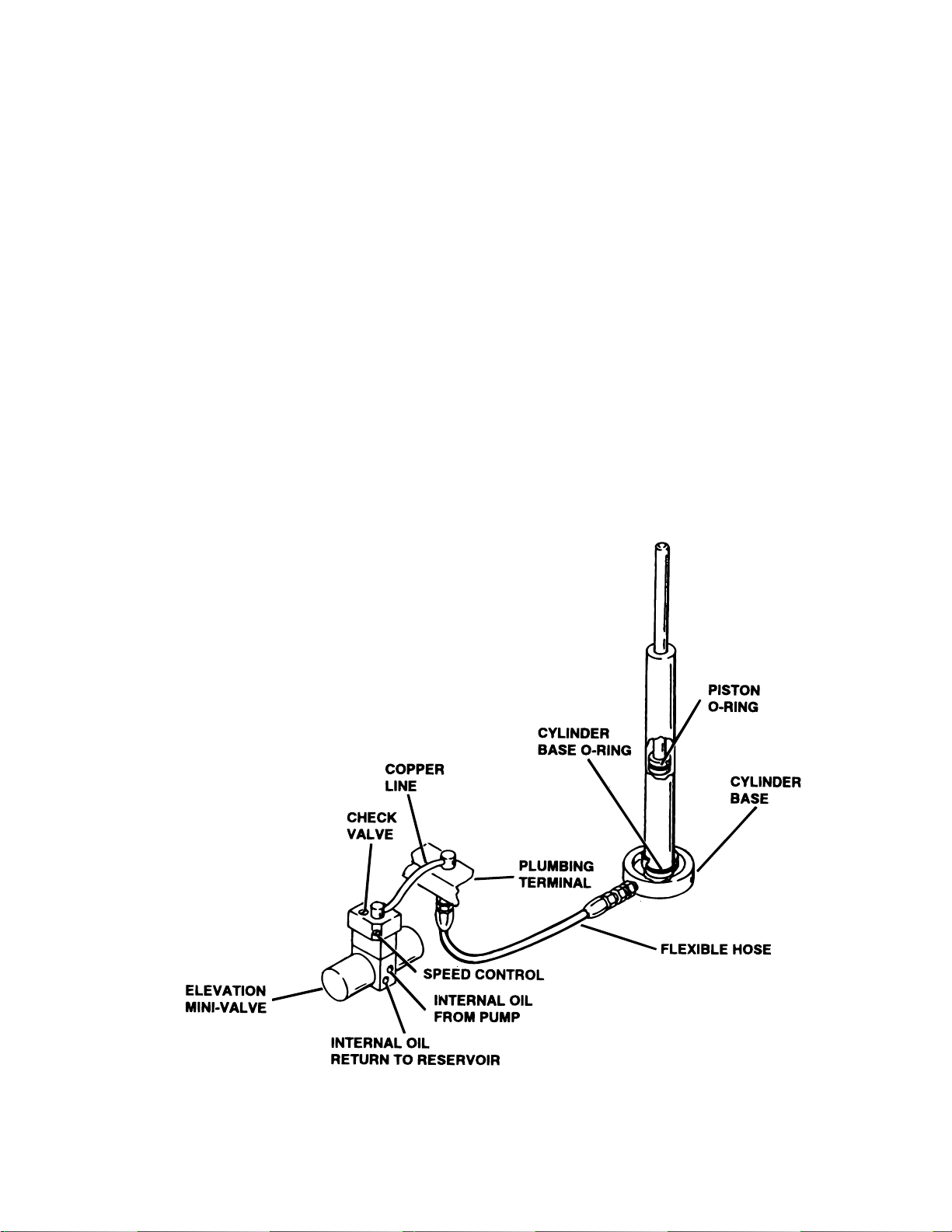
3-3. ELEVATION DIAGNOSIS CHART
Problem
Table will not elevate properly
Table will not descend properly
Table loses elevation
Reason
Pressure Relief Valve Not Set Properly
Low on Oil
Spool Valve Not Centered
Defective Pump
Defective Mini-Valve
Defective Solenoid or Wiring
Defective Relay Box or Pendant Control
Incorrect Speed Adjustment
Bad Check Valve
Spool Valve Not Centered
Galled Slider Assembly
Defective Solenoid or Wiring
Defective Relay Box or Pendant Control
Bad Check Valve
Leaking Mini-Valve
Loose Fittings, Joints, Hoses
Leaking "O" Ring Inside Cylinder
Figure 3-1. Elevation Circuit
Page 13

P
M
3-4. TRENDELENBURG DIAGNOSIS CHART
Problem
Trendelenburg function moves improperly
Trendelenburg function chatters or loses position
PINION
GEAR
O-RING
FRONT PIVOT
BLOCK
Reason
Incorrect Speed Adjustment
Spool Valve Not Centered
Bad Check Valves
Low on Oil
Pinched Hose
Defective Mini-Valve
Pressure Relief Valve Not Set Properly
Bad Solenoid or Wiring
Defective Relay Box or Pendant Control
Defective or Dirty Check Valve
Oil Leakage in Circuit
Air Inside Cylinder
Pinched Hose
Low on Oil
REAR PIVOT
BLOCK
O-RING
TAIL CYLINDER CA
PISTON
ASSEMBLY
HEAD
CYLINDER
CAP
HEAD DOWN
CIRCUIT
COPPER
LINES
CHECK VALVE
SPEED
CONTROL
INI-VALVE
PLUMBING
TERMINAL
O-RING
FLEXIBLE
HOSES
HEAD UP
CIRCUIT
INTERNAL OIL
FROM PUMP
INTERNAL OIL RETURN
TO RESERVOIR
Figure 3-2. Trendelenburg Circuit
Page 14
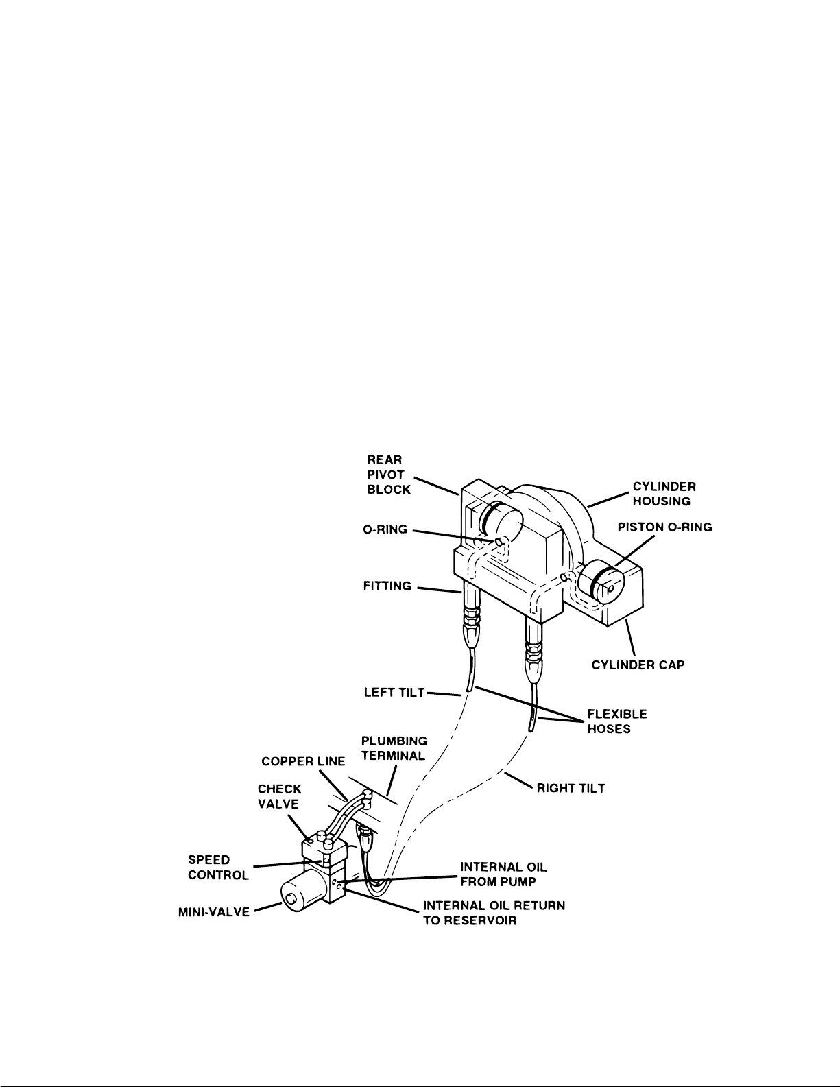
3-5. LATERAL TILT DIAGNOSIS CHART
Problem
Lateral tilt function moves improperly
Lateral tilt function chatters or loses position
Reason
Incorrect Speed Adjustment
Spool Valve Not Centered
Bad Check Valves
Low on Oil
Pinched Hose
Defective Mini-Valve
Pressure Relief Valve Not Set Properly
Bad Solenoid
Defective Relay Box or Pendant Control
Defective or Dirty Check Valves
Oil Leakage in Circuit
Air Inside Cylinder
Pinched Hose
Low on Oil
Figure 3-3. Lateral Tilt Circuit
Page 15

3-6. FLEX SYSTEM DIAGNOSIS CHART
Problem
Back Section or Trendelenburg function moves
improperly
NOTE
If Flex System does not function properly, check the back section and trendelenburg functions before adjusting
the flex system.
Back Section or Trendelenburg function chatters
or loses position
Reason
Incorrect Speed Adjustment (Trendelenburg, Back
section or Flex - check with gauge)
Spool Valve Not Centered
Bad Check Valves
Low on Oil
Pinched Hose
Defective Mini-Valve
Pressure Relief Valve Not Set Properly
Bad Solenoid
Defective Relay Box or Pendant Control
Defective or Dirty Check Valves
Oil Leakage in Circuit
Air Inside Cylinder
Pinched Hose
Low on Oil
Page 16
Figure 3-4. Flex System Circuit
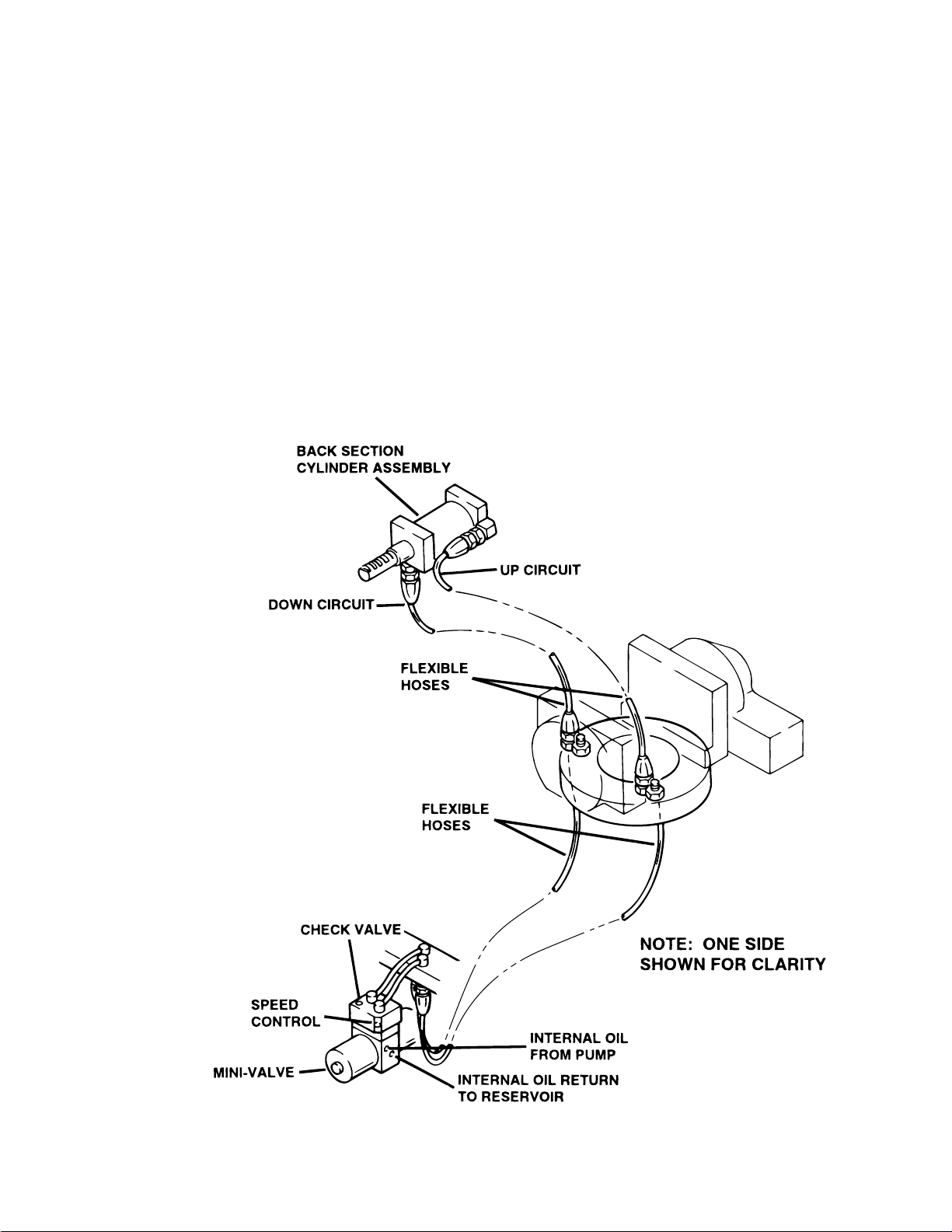
3-7. BACK SECTION DIAGNOSIS CHART
Problem
Back Section function moves improperly
Back Section function chatters or loses position
Reason
Incorrect Speed Adjustment
Spool Valve Not Centered
Bad Check Valves
Low on Oil
Pinched Hose
Defective Mini-Valve
Pressure Relief Valve Not Set Properly
Bad Solenoid
Defective Relay Box or Pendant Control
Defective or Dirty Check Valves
Oil Leakage in Circuit
Air Inside Cylinder
Pinched Hose
Low on Oil
Figure 3-5. Back Section Circuit
Page 17
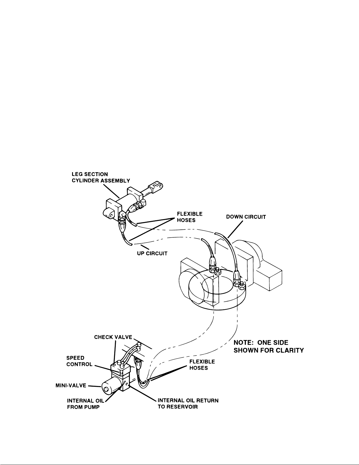
3-8. LEG SECTION DIAGNOSIS CHART
Problem
Leg function moves improperly
Leg function chatters or loses position
Reason
Incorrect Speed Adjustment
Spool Valve Not Centered
Bad Check Valves
Low on Oil
Pinched Hose
Defective Mini-Valve
Pressure Relief Valve Not Set Properly
Bad Solenoid
Defective Relay Box or Pendant Control
Defective or Dirty Check Valves
Oil Leakage in Circuit
Air Inside Cylinder
Pinched Hose
Low on Oil
Page 18
Figure 3-6. Leg Section Circuit

C
E
3-9. BRAKE CIRCUIT DIAGNOSIS CHART
Problem
Brakes will not set properly
NOTE
If brakes have been released with the
Emergency Brake Release Valve,
brakes will not reset until BRAKE UNLOCK Circuit has been activated.
Brakes Will Not Stay Locked
Brakes will not retract properly
Reason
Emergency Brake Release Valve Open or Defective
Spool Valve Not Centered
Bad Check Valve
Low on Oil
Pressure Relief Valve Not Set Properly
Pinched Hose
Defective Mini-Valve
Defective Relay Box or Pendant Control
Emergency Brake Release Valve Open or Defective
Defective or Dirty Check Valve
Oil Leakage in Circuit
Leaking "O" Ring Inside Cylinder
Incorrect Speed Adjustment
Bad Check Valve
Spool Valve Not Centered
Defective Mini-Valve
Pinched Hose
Defective Solenoid or Wiring
Defective Relay Box or Pendant Control
BRAKE
CYLINDER
PLUMBING
TERMINAL
BRAKE
CYLINDER
HECK V AL VE
SPEED
CONTROL
MINI-VALVE
INTERNAL OIL
FROM PUMP
INTERNAL OIL RETURN
TO RESERVOIR
FLEXIBLE
HOSES
BRAKE
CYLINDER
COPPER LINE
FLEXIBLE
HOSES
FLEXIBLE
HOSE
RETURN TO
RESERVOIR
EMERGENCY
BRAKE RELEAS
RELEASE LEVER
Figure 3-7. Brake System Circuit
Page 19

F
P
T
F
P
B
)
3-10. Flexible Hose Identification and
Placement
The following figures will show the correct placement of the flexible hydraulic hoses used in the
table and their respective number codes.
Figure 3-8 shows the hose connections to the
plumbing terminal.
2468
13579
NUMBER
1
2
3
4
5
6
7
8
9
FUNCTION
ELEVATION
REV TREND
TREND
LA T TIL T LEFT
LA T TIL T RIGHT
BACK DOWN
BACK UP
LEG UP
LEG DOWN
Figure 3-8. Main Plumbing Terminal
Figure 3-9 shows the placement of the short flexible hoses which connect to the back section
cylinders.
BACK CYLINDER, RAM (RIGHT)
Figure 3-10. Leg Section Hoses
Figure 3-11 shows the placement and number
code for the long flexible hoses which connect from
the plumbing terminal to the front and rear pivot
blocks.
NOTE
The number codes will be stamped into
the elevation clamp ring and the plumbing terminal.
(3) TREND.
RONT
IVOT BLOCK
(5) LAT. TILT RIGHT
(4) LAT. TILT LEFT
TOP VIEW
REAR PIVO
BLOCK
(2) REV. TREND
BACK CYLINDER, RAM (LEFT)
Figure 3-11. Pivot Block Hoses
Figure 3-12 shows the placement and number
code for the long flexible hoses that connect from
RONT
TOP VIEW
IVOT
LOCK
BACK CYLINDER, PISTON (RIGHT
BACK CYLINDER, PISTON (LEFT)
the elevation clamp ring to the plumbing terminal.
Figure 3-9. Back Section Hoses
Figure 3-10 shows the placement of the short
flexible hoses which connect to the leg section
cylinders.
Page 20
Figure 3-12. Elevation Clamp Ring Hoses
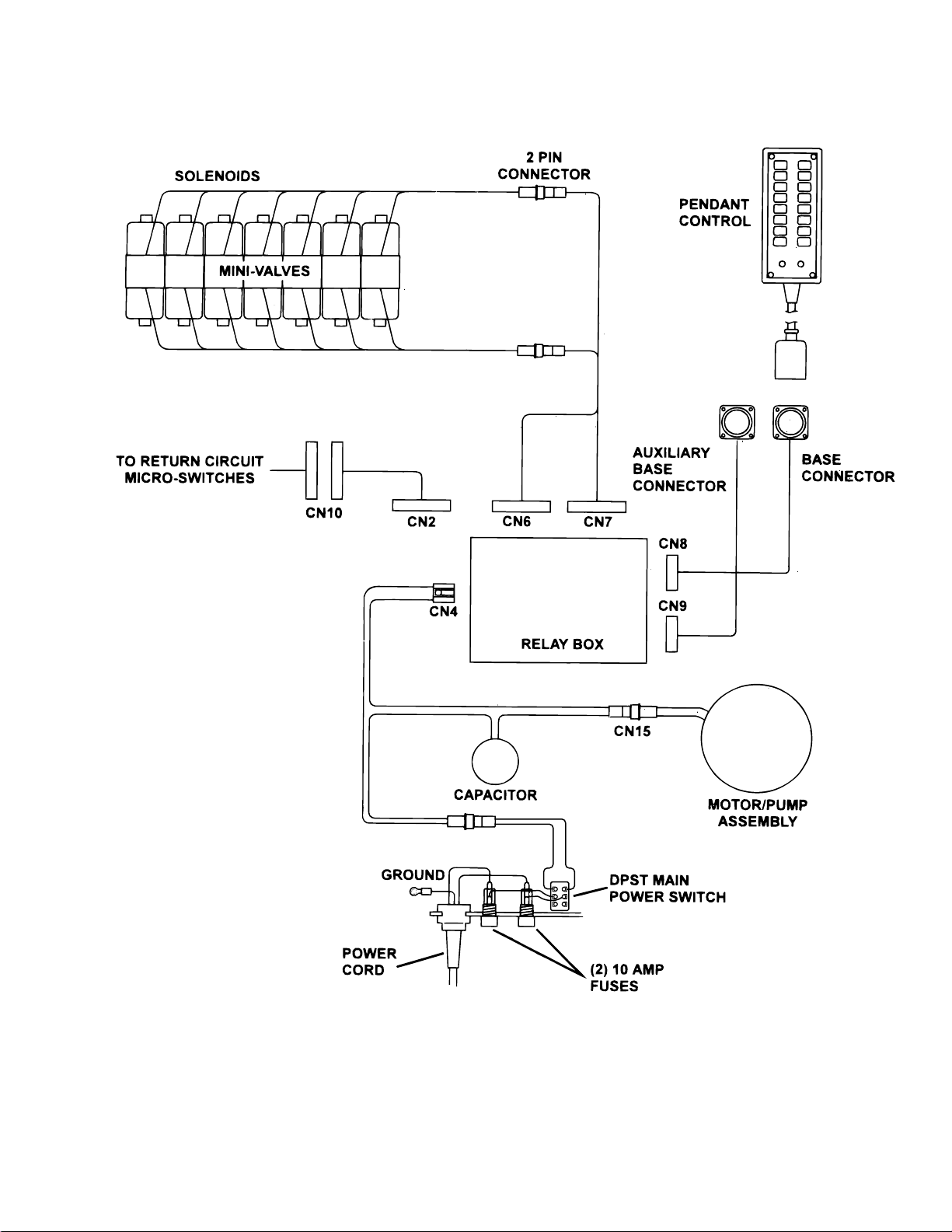
Figure 4-1. 6002 Electrical Circuit Block Diagram
Page 21

SECTION IV ELECTRICAL SYSTEM
4-1. General
The complete electrical system (with the exception of the hand-held pendant control and the return
circuit micro-switches) is contained within the base
of the table. The pump motor and the hydraulic
valves are controlled electrically with the pendant
control.
The electrically operated functions are as follows:
- ELEVATION - Up and Down
- TRENDELENBURG - Head up and down
- LATERAL TILT - Right and left
- BACK SECTION - Up and Down
- LEG SECTION - Up and Down
- FLEX / REFLEX
- RETURN TO LEVEL
4-2. Components
Refer to figure 4-1 for the relationship of the electrical components.
a. Wires, Connectors, Switches, Fuse - These
provide the path for the various electrical circuits.
b. Relay Box - Contains the step down transformer, full wave rectifier, and relay switches. The
relay switches are activated by the pendant control
and in turn energize the solenoid.
c. Hand-Held Pendant Control - Closes microswitches to activate relay box. Operates on 5
VDC.
d. Solenoids - These electrically open and
close the hydraulic ports of the mini-valve to direct
the fluid to the correct cylinders. They operate on
120 VAC.
e. Motor/Pump Assembly - 120 VAC, 60 HZ,
200 Watt capacitor induction motor.
- BRAKE UNLOCK - Brake release
The power requirements are 120 VAC, 60 Hz, fuse
protected. The main power on-off switch is an
enclosed DPST type and the power cord is a threewire, fifteen foot long, UL listed cord with a threeprong hospital grade plug.
4-3. Battery Model Components
The functions of the battery model tables are the
same as the standard 120 VAC models. The
electrical components and operation however, vary
greatly between the two models. To simplify the
troubleshooting procedures, the battery model
tables are covered separately in Section VI.
Page 22
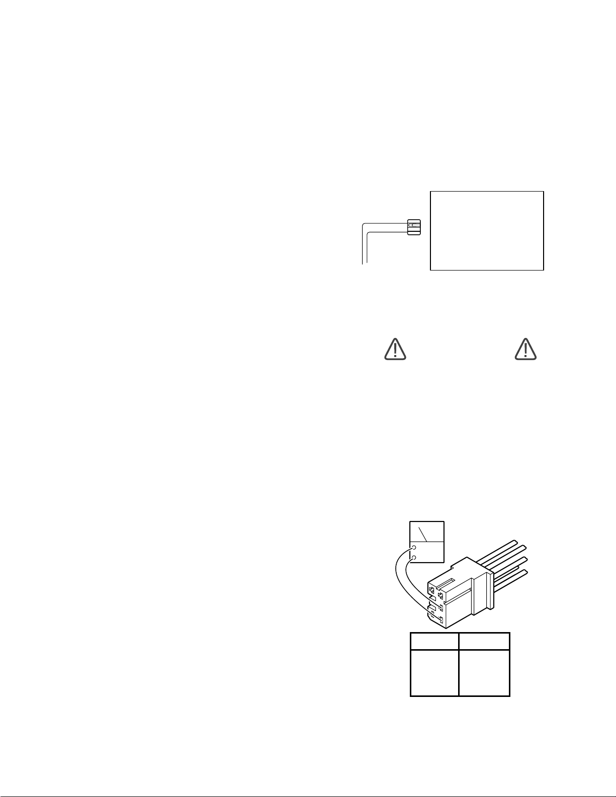
SECTION V ELECTRICAL SYSTEM TROUBLESHOOTING
5-1. Troubleshooting Notes
The basic operation of each component will be
defined along with a drawing and explanation on
how to check it out.
NOTE
This section does not cover the battery table components. They are
covered separately in Section 6.
Certain defective components could cause the
entire table to stop functioning or only one control
function to stop. It would depend on what part of the
component failed. Other defective components would
only cause one control function to stop.
The following defective components could cause
all control functions to be affected:
a. Motor/Pump Assembly (starting capacitor)
b. Main Switch Circuit and Wiring
The following defective components could cause
all control functions to be affected or only one
control function:
a. Relay Box
b. Pendant Control
The component listed below would only affect one
control function:
Solenoid
1. Plug the power cord into the 120VAC power
supply (wall receptacle) and turn ON the main
switch.
2. Disconnect connector CN4 from the relay
box. See figure 5-1. Leave all other connectors
connected.
RELAY BOX
CN4
Figure 5-1. Main Power Test
WARNING
Line voltage (120 VAC) will be measured in this test. Do not touch uninsulated connector pins or meter test leads.
3. Use an AC voltmeter capable of measuring
120 VAC and measure the voltage between pins
1 and 2 (black and white wires) located in connector CN4. See figure 5-2. You should receive line
voltage 120 VAC.
When troubleshooting an electrical circuit, start at
the problem and work back to the power source.
5-2. Main Switch
The main power supply, 120 VAC, 60 HZ, comes in
through the power cord and through the main
switch. The main switch opens both lines when in
the "OFF" position. An 8 amp or two 10 amp fuses
are used to protect the complete electrical system
and are located next to the main switch.
a. Main Switch Test
The following test will determine if line voltage is
applied to connector CN4, which in turn would
power the table.
ACV
5
3
2
4
1
PIN NO. COLOR
1 White
2 Black
3 Red
4 Blue
5 Yellow
Figure 5-2. Connector CN4
Page 23

b. Test Results
If you do not receive the correct voltage measurement, the problem would have to be in the wires,
main switch, fuses, or power cord. If the correct
voltage is obtained, everything is good up to this
point and the problem would have to be in another
area.
5-3. Pendant Control
The Pendant Control consists of 14 micro-switches
(buttons). When any of the circuits are completed
(by depressing a control button) the appropriate
relay contacts (located in the relay box) close
applying 120V potential to the appropriate solenoid
to operate the mini-valve and the pump/motor. The
Pendant Control has only 5-6 volts applied to it.
a. Pendant Control Test
The following test will determine if the microswitches inside the Pendant Control are functioning correctly.
1. Unplug the pendant control from the base of
the table. You will be checking the cord side
connector.
2. Use an ohmmeter R x 1 scale and check the
continuity between pin 1 and pins 4 through 19.
See figure 5-3.
3. Ohmmeter must show continuity between
the pins that are indicated when the appropriate
buttons are pressed.
NOTE
Pins 2 and 3 are connected to the LED
(power on light on the pendant control)
and cannot be checked with an ohmmeter. Pins 17 & 18 are not used.
Page 24
Figure 5-3. Pendant Control Test

b. Test Results:
If you do not receive continuity between any of the
pins, either the micro-switch in the Pendant Control
is defective or a wire is broken. Either of these
problems can be repaired easily.
If you receive correct readings with the meter, the
Pendant Control is okay.
c. Wiring Harness Test
The following test checks the wires leading from
the relay box connector CN8 to the 19 pin connector table socket. These wires apply low voltage to
the pendant control buttons.
1. The power cord should be plugged into the
wall socket and the main switch turned ON.
d. Test Results:
If you do not receive the correct voltage reading,
the wiring or connector pins may be faulty. Disconnect connector CN8 from the relay box and using
an ohmmeter, test the continuity between the corresponding pins in connectors CN8 and the table base
connector. See figure 5-5. If the correct readings are
obtained, this part of the circuit is okay.
OHM
CN8
2. Disconnect the pendant control from the
base connector. All other connectors should be
connected.
3. Use a DC voltmeter 10V scale and measure
the following pins located in the 19 pin table base
connector. See figure 5-4.
NOTE
Pin 19 will have no voltage potential unless one of the return-to-level microswitches are activated, i.e. trend or tilt .
Pins 17 & 18 are not used.
PIN NO.
1
2
3
4
5
6
7
8
9
10
COLOR PIN NO. COLOR
Red/White
White
Black
Red
White/Red
Yellow
Brown
White/Brown
Blue/White
Orange
11
12
13
14
15
16
17
18
19
White/Orange
White/Gray
White/Yellow
Purple/White
Black/White
White/Purple
Blue/Yellow
Gray
Purple
Figure 5-5. Base Connector Continuity Test
5-4. Relay Box
The 120 volt power supply is directly connected to
the relay contacts. When these contacts are
closed, 120 volts is supplied to the solenoids which
are mounted on the hydraulic mini-valves. One
relay is used to supply 120V to the pump/motor and
is always activated no matter what control function
is selected. The brake locking circuit relay is also
activated when any control function other than
BRAKE UNLOCK is initially selected.
Also, inside the relay box is a step-down transformer
and full-wave rectifier which decreases the line voltage to 5.5 volts. This low voltage potential controls
the relays by the use of the hand-held pendant
control buttons. Basically the relays enable a 5.5
volt potential to control the 120 volt circuit.
Figure 5-4. Table Base Connector
The following tests will determine if the relay box is
functioning correctly.
a. Relay Box Input Connector CN4
1. Plug the power cord into the 120 VAC power
supply (wall receptacle) and turn the main switch
ON. Leave all connectors connected.
Page 25
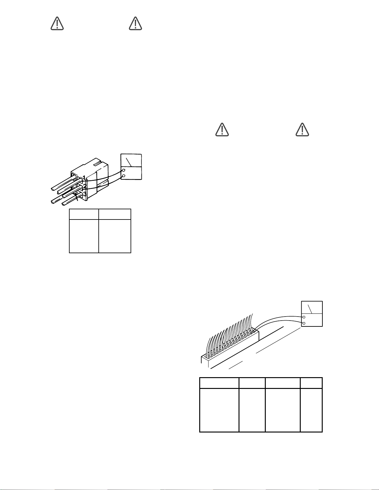
WARNING
d. Test Results:
Line voltage (120 VAC) will be measured in this test. Do not touch uninsulated connector pins or meter test leads.
2. Use an AC voltmeter capable of measuring
120 volts and measure the voltage between pins 1
(white) and 2 (black) of connector CN4 for input
voltage. See figure 5-6. Meter should read line
voltage 120 VAC.
3. Activate any table function with the Pendant
Control and using an AC voltmeter, test the voltage
at pins 3 and 4 of CN4 for output to the pump. Meter
should read 120 VAC.
4
5
PIN NO.
1
2
3
4
5
COLOR
WHITE
BLACK
RED
BLUE
YELLOW
ACV
Figure 5-6. Connector CN4
b. Test Results:
If you do not receive the correct meter readings, the
relay box or wiring is defective. If the correct
readings are obtained, this part of the relay box is
okay. Proceed to the next step.
If you do not receive the correct meter readings, the
relay box or wiring is defective. If the correct
readings are obtained, this part of the relay box is
okay. Proceed to the next step.
e. Relay Box Output Connectors CN6 & CN7
This test checks the high voltage (120V) that is
used to energize the solenoids.
WARNING
120 VAC will be measured in this test.
Do not touch uninsulated connector
pins or meter test leads.
1. The power cord should be plugged into the
wall receptacle and main switch turned ON.
2. Disconnect the motor connector CN15. All
other connectors should be connected. Test connectors CN6 and CN7 from the back while attached
to the relay box.
3. Activate each of the Pendant Control buttons and using an AC voltmeter capable of measuring 120VAC, measure the voltage between the
appropriate connector pins located in connector
CN6 or CN7. See figure 5-7. Polarity of meter test
leads is not important. Meter should read 120VAC.
ACV
c. Relay Box Output Connector CN8
This test checks the low voltage applied to the pendant control buttons.
1. The power cord should be plugged into the
wall receptacle and main switch turned ON.
2. Disconnect Pendant Control connector. All
other connectors should be connected.
3. Using a DC voltmeter, measure the voltage
between pin 1(+) and pins 4 through 19(-) of the
table base connector. See figure 5-4. Meter
should read 5-6 volts.
Page 26
1
CN6 OR CN7
16
Leg Up
Flex
Reflex
CN7
1 - 2
3 - 4
9 - 10
11 - 12
13 - 14
15 - 16
CN6
FUNCTION PINS FUNCTION PINS
Table Up
Table Down
Rev Trend
Trend
Back Up
Back Down
Tilt Right
Tilt Left
1 - 2
3 - 4
5 - 6
7 - 8
9 - 10
11 - 12
13 - 14
15 - 16
Leg Down
Brake Set
Brake Unlock
Figure 5-7. Relay Box Output Connectors
CN6 and CN7

f. Test Results:
If you do not receive the correct meter readings, the
relay box or wiring is defective and should be
replaced.
NOTE
Before deciding the relay box is defective, check the wires and pins in the
connector blocks to make sure they are
not loose or making a bad connection
with their mate.
5-5. Solenoids
The solenoids are energized by 120 volt potential
that is controlled by the relays located inside the
relay box.
The solenoid windings are protected from excessive heat with an internal thermal fuse that will open
after approximately seven (7) minutes of continuous operation. The solenoid must be replaced if
the internal thermal fuse has been blown. The
solenoids are mounted directly on either side of the
hydraulic mini-valves and push the spool valve in
one direction or the other depending upon which
solenoid is activated.
WARNING
Line voltage will be measured in this
test. Do not touch uninsulated connector pins or meter test leads.
b. Step #1
1. Plug the table cord into the wall receptacle
and turn main switch ON.
2. Disconnect the 2 pin connector from the
solenoid in question. See figure 5-8.
3. Use a voltmeter capable of measuring 120
VAC and measure the voltage across the 2 pin
connector. Polarity of meter leads is not important.
NOTE
The appropriate pendant control button must be pushed during this test.
The motor will run when this test is
performed, and the brake locking solenoid will be activated by any function
other than UNLOCK.
c. Test Results:
a. Solenoid Test
The following tests check the voltage applied to the
solenoids and the resistance of the solenoid coil.
NOTE
If a solenoid does not function when the
pendant control button is pushed, the
problem could be the pendant control,
the relay box, or the solenoid.
NOTE
Each solenoid is controlled with 120V
source coming from the relay box. This
source can easily be checked by measuring the voltage at the 2 pin connector in question.
If you do not receive the correct voltage, the problem could be in the wires leading to connectors
CN6 and CN7. The problem could also be in the
relay box or the Pendant Control (refer to appropriate section for troubleshooting).
If the correct voltage is obtained, everything is
good up to that point and the problem is more than
likely the solenoid.
d. Step #2
The solenoid can be checked out using an ohmmeter R x 1 scale.
1. Measure the resistance between the two
pins of the connector in question. See figure 5-8.
Connector being tested must be disconnected.
Polarity of meter leads is not important.
2. The meter should read approximately 80-90
ohms at room temperature.
Page 27
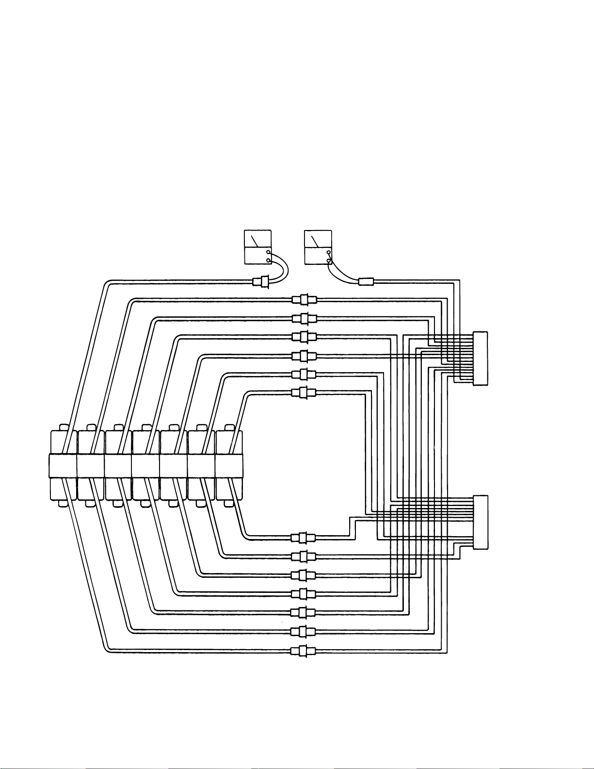
Y
Y
3. Measure the resistance between either pin
and ground.
4. Meter should read infinity.
e. Test Results:
If the solenoid does not check out with the meter, it
is more than likely defective and must be replaced.
OHM ACV
NOTE
Whenever there are several components of the same type, a defective unit
can also be detected by substituting a
known good unit or wire connector. In
some cases this may be faster than
using a multi-meter.
UP
DN.
TABLE TREND
HD.
DN.
UP
BLUE
WHITE/BLUE
UN-
DN.UPREFXRT.HD.
LCK.
LAT.
TILT
LT.
FLEX
BACK
FLEX
SECT.
DN. UP SET
LEG
SECT.
BRAKE
BLUE
WHITE/BLUE
BLUE
WHITE/BLUE
BLUE
WHITE/BLUE
BLUE
WHITE/BLUE
BLUE
WHITE/BLUE
BLUE
WHITE/BLUE
BLUE
WHITE/BLUE
BLUE
WHITE/BLUE
BLUE
WHITE/BLUE
BLUE
WHITE/BLUE
BLUE
WHITE/BLUE
BLUE
WHITE/BLUE
BLUE
WHITE/BLUE
BLUE
BROWN
BLUE
ORANGE
BLUE
BROWN/WHITE
BLUE
WHITE/BROWN
BLUE
WHITE/GRAY
BLUE
BLACK/WHITE
BLUE
WHITE/BLACK
BLUE
GRAY
BLUE
BLUE/WHITE
BLUE
RED/WHITE
BLUE
WHITE/ORANGE
BLUE
YELLOW
BLUE
WHITE/RED
BLUE
RED
CN6
16
TO
RELA
BOX
1
CN7
16
TO
RELA
BOX
1
Page 28
Figure 5-8. Solenoid Test
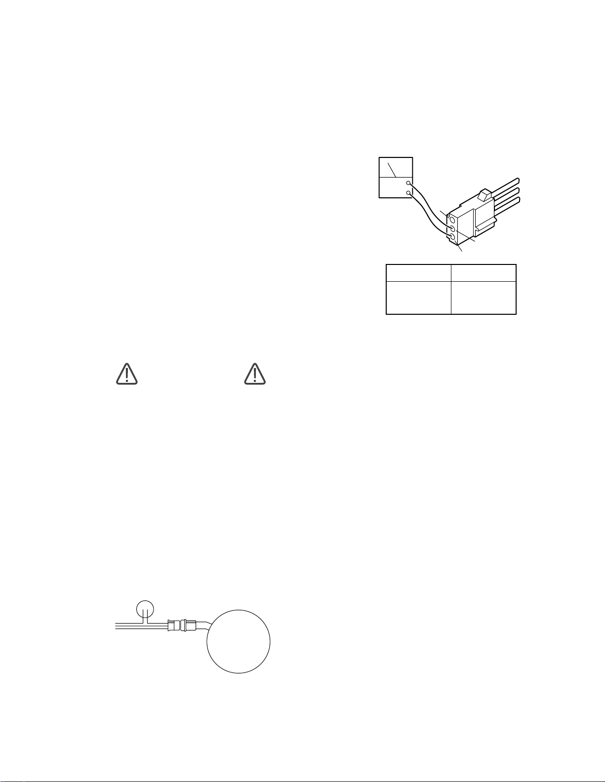
5-6. Motor/Pump Assembly
The electric motor is a capacitor start type with a
rating of 120 VAC, 200 watts. The field windings
are protected with a thermal protector that will open
the winding circuit if the motor is run continuously
for approximately 10 minutes. This protector will
take about 10 minutes to automatically reset. The
oil pump unit is attached to the bottom of the motor
and is a gear type displacement pump with a
pumping capacity of .4 liter per min. The Motor/
Pump Assembly is mounted on an insulated motor
plate in the base of the table. The starting capacitor
is mounted along side the motor/pump assembly
a. Motor/Pump Test
The following tests will check the voltage applied to
the motor and the resistance of the motor field
windings.
3. Use a voltmeter capable of measuring 120
VAC and measure the following connector pins in
connector CN15. See figure 5-10.
ACV
3
2
1
PIN NO
1 - 2
1 - 3
2 - 3
AC VOLTS
120
120
0
Figure 5-10. Connector CN15
WARNING
Line voltage will be measured in this
test. Do not touch uninsulated connector pins or meter test leads.
b. Step #1
1. Plug the power cord into 120 VAC power
supply (wall receptacle). Turn main switch ON.
2. Disconnect the 3 pin connector CN15 at the
motor. Leave all other connectors connected. See
figure 5-9.
CAPACITOR
CN15
PUMP
c. Test Results:
If you do not receive the correct meter readings, the
problem could be in the wires, connectors, relay
box, or main switch (refer to appropriate section for
troubleshooting).
If the correct voltage is obtained, everything is
good up to that point and the problem could be
either the motor or the starting capacitor.
d. Step #2
If the starting capacitor is shorted or grounded, the
motor will not run. Capacitors very seldom fail, and
it requires a dielectric tester to accurately test one.
However, an ohmmeter can be used to determine
if the capacitor will store a low voltage charge and
most of the time this is adequate.
1. Turn the main switch OFF.
Figure 5-9.
2. Connector CN15 should be disconnected.
3. Use the R x 100 scale of the ohmmeter and
touch pins 2 and 3 of connector CN15. See figure
5-10.
Page 29
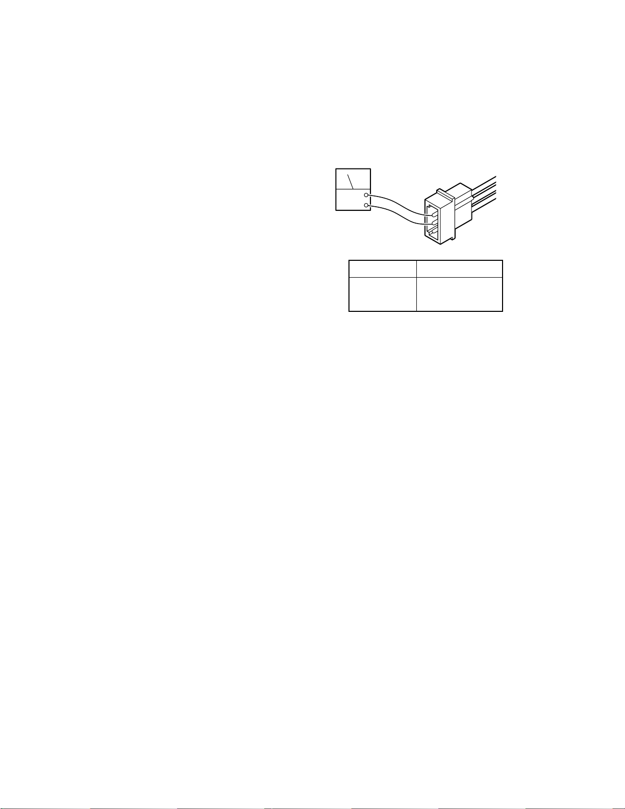
e. Test Results:
The meter needle should move up scale and then
back down to infinity. This would indicate that the
capacitor is storing an electrical charge.
NOTE
The capacitor may have to be discharged first (by shorting pins 2 and 3
together) before you will be able to see
the ohmmeter needle swing up the scale.
OHM
f. Step #3
The motor windings can be statically checked for
resistance using an ohmmeter.
1. Turn main power switch OFF.
2. Connector CN15 should be disconnected.
3. Use the R x 1 scale of the ohmmeter and
measure the resistance between the pins located
in the pump connector CN15. See figure 5-11.
PIN NO
1 - 2
1 - 3
2 - 3
METER
Approx. 5 ohms
Approx. 4 ohms
Approx. 8 ohms
Figure 5-11. Pump Connector CN15
g. Test Results:
If you do not receive the correct meter readings, the
motor or wiring is defective.
Page 30
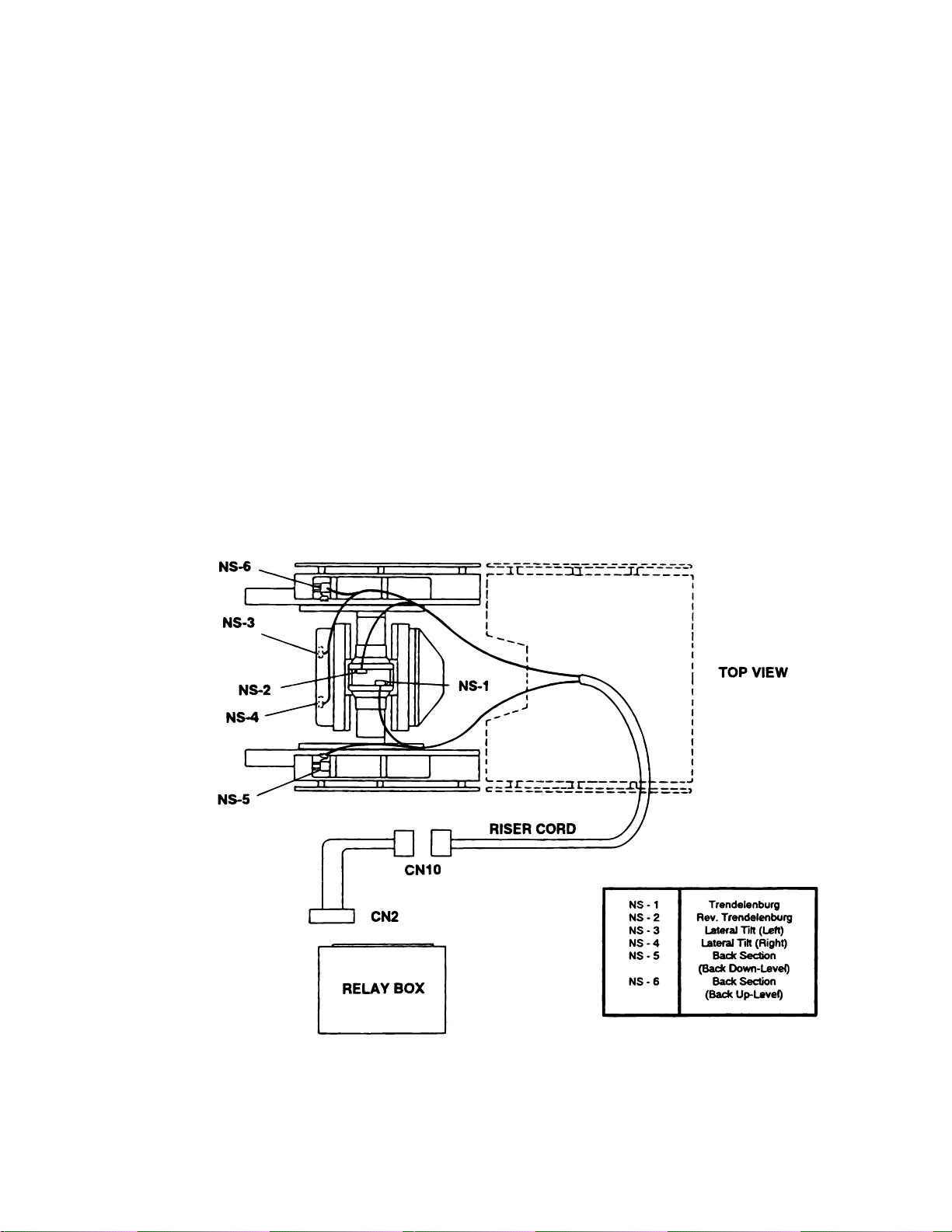
5-7. Return-to-Level Micro-Switches.
The return-to-level feature is activated by a single
button on the pendant control and automatically
levels the major table functions, lateral tilt, trendelenburg, back section, and leg section.
The return-to-level system consists of 6 microswitches, 2 electrical connectors, and the related
wiring. The micro-switches are mounted on or
adjacent to the function they control and are wired
for normally open or normally closed operation.
The micro-switches are lever actuated and can be
adjusted at the individual switch mounting brackets. See figure 5-12.
The micro-switches operate on low voltage, and
control the function circuits (pump/motor and appropriate solenoid valves) when activated by the
pendant control RETURN button.
The micro-switches are wired to the relay box
through a riser cord and to the 15 pin connector
CN2. See figure 5-12 for switch location and
identification.
5-8. Troubleshooting
If a problem is suspected in the return circuits,
disconnect the connector CN2 from the Relay Box
to eliminate the circuits. Ensure that all table
functions operate properly using the Pendant Control. If the functions do not work properly using the
Pendant Control, refer to the appropriate test section and make all needed repairs before working on
the return circuits.
Figure 5-12.
Page 31
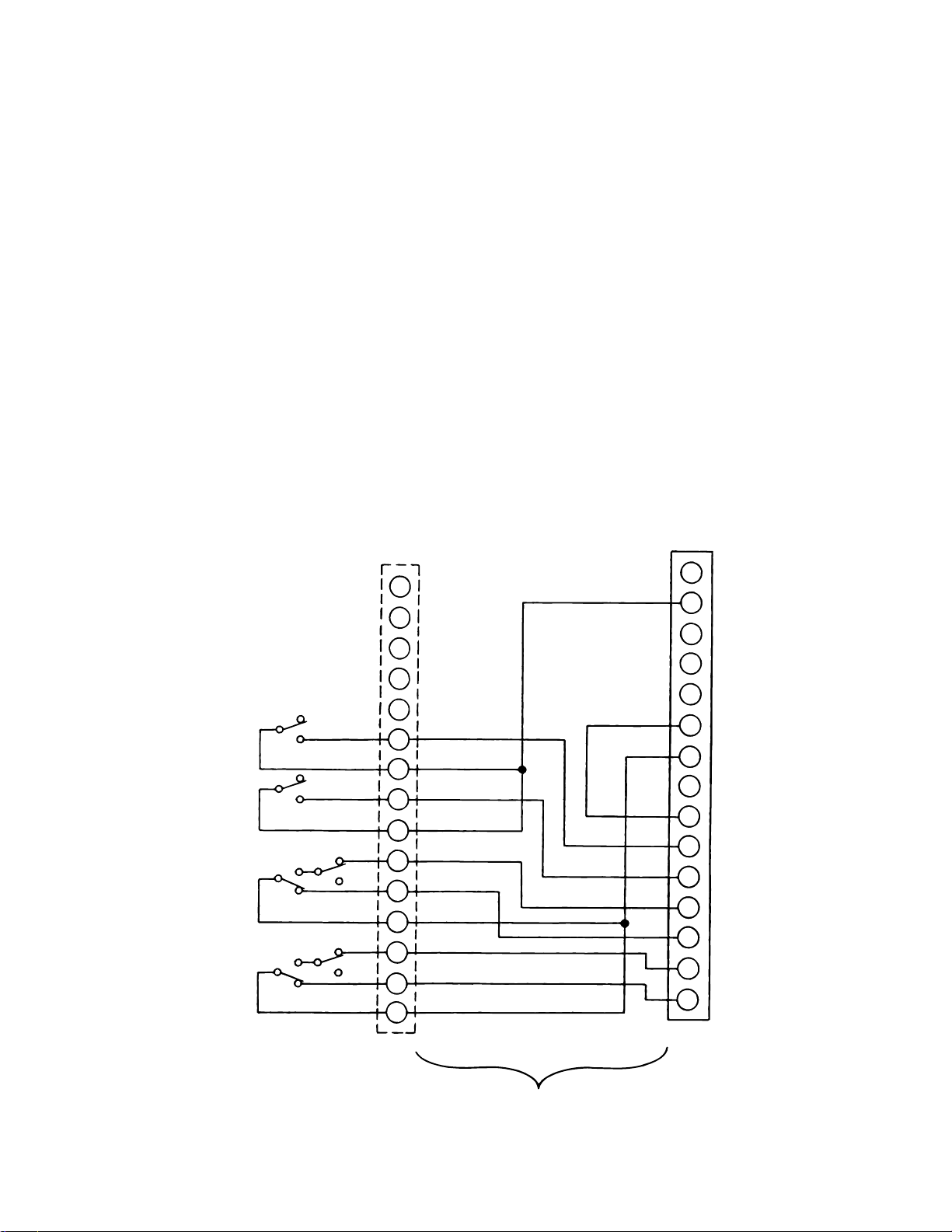
B
NOTE
It is normal for the back section to move
up if the RETURN button is pushed
when connector CN2 is disconnected
from the relay box.
operation at the appropriate pin numbers for the
micro-switch in question as shown in figures 5-14
through 5-18.
NOTE
All of the micro-switches are connected to the relay
box via a wiring harness and the micro-switch riser
Be sure to isolate the circuit when mak-
ing continuity checks.
cord using connectors CN2 and CN10. Connector
CN10 is located under the slider shroud in the same
area as the hydraulic hoses. Connector CN2 plugs
NOTE
into the relay box and is the most convenient
location to make circuit continuity checks. See
figure 5-13 for connector pin locations.
If you do not receive the proper continu-
ity results at connector CN2 it does not
necessarily mean the micro-switch is
a. Switch Test
defective. There could be a problem
with the riser cord between connectors
Turn Main Power ON, lock the table brakes, and
place the table top sections in a level position.
Disconnect connector CN2 from the relay box and
using an ohmmeter, test the wiring and switch
16
15
8
7
13
BR/WHITE
BACK UP
ACK DOWN
TILT LEFT
TREND
NS-6
NS-5
TILT RIGHT
NS-4
NS-3
REVERSE
TREND
NS-2
NS-1
6
12
5
11
4
3
10
2
1
9
CN10
PURPLE
BLUE
PINK
GREEN
YELLOW
BROWN
WHITE
RED
ORANGE
CN2 and CN10, or in the wiring from the
switch to connector CN10. Further
tests will have to be made to determine
the exact problem.
15
PINK
BLACK/WHITE
14
13
12
11
10
9
8
7
6
5
4
3
2
1
CN2
Page 32
RISER CORD
Figure 5-13. Return Micro-Switch Test
 Loading...