


ELITE SERIES SURGICAL TABLES
OPERATORS MANUAL
MODEL ELITE 3500
INCLUDING BATTERY MODELS
29


MODEL ELITE 3500
SKYTRON STANDARD LIMITED WARRANTY
SKYTRON, a Division of the KMW Group, Inc. (SKYTRON) warrants all new products sold by it directly or through a dealer or other
authorized representative, with exception to replacement parts, spares, bulbs (surgical lights), pads, and accessory items (surgical tables)
to be free from defects in material or workmanship, under normal use and service, for a period of two (2) years. This warranty shall include
the cost of repair or replacement of defective parts including the cost of service labor and travel time to the site of equipment use. Delays
caused by the user in accessing the equipment for repair will be chargeable at the normal hourly rate for service by SKYTRON’s authorized
service representative. The warranty period shall begin with the initial operation or one (1) year after receipt of the product, whichever shall
occur first.
Replacement parts, spares, bulbs (surgical lights), pads and accessory items (surgical tables) are warranted to be free from defects in material
or workmanship, under normal use and service, for a period of ninety (90) days from receipt by the ultimate user, with exception to replacement
parts supplied by SKYTRON, for products under warranty, which shall be covered for any remaining period of the original product warranty,
or for 90 days, whichever is of greater benefit to the ultimate user.
SKYTRON’s responsibility and liability shall be limited to the repair or replacement of any part which we, SKYTRON, determine to be defective
within the applicable warranty period. Minor adjustments required as a result of normal wear during the use of the product within the warranty
period are not covered under warranty. The labor portion of this warranty is covered by SKYTRON’s Authorized Service Agent. Repairs
made by others are not authorized nor covered by SKYTRON with respect to labor costs.
SKYTRON shall not be liable for any other expense, loss or damage, whether direct, incidental, consequential or exemplary arising in connection
with the sale or use of or the inability to use SKYTRON products.
NO EXPRESS WARRANTY IS GIVEN BY SKYTRON WITH RESPECT TO ITS PRODUCTS EXCEPT AS SPECIFICALLY SET FORTH
HEREIN. ANY WARRANTY IMPLIED BY LAW, INCLUDING ANY WARRANTY OF MERCHANTABILITY OR FITNESS FOR A PARTICULAR
PURPOSE, IS EXPRESSLY LIMITED TO THE TWO-YEAR AND 90-DAY TERMS SET FORTH ABOVE. THE FOREGOING STATEMENTS
OF WARRANTY ARE EXCLUSIVE AND IN LIEU OF ALL OTHER REMEDIES.
No dealer, agent, employee or other representative of SKYTRON is authorized to extend or enlarge this warranty.
REV. 10/02
Although current at the time of publication, SKYTRON’s policy of continuous development makes this
manual subject to change without notice.
27


TABLE OF CONTENTS
Title Page
EQUIPMENT LABELS AND SPECIFICATIONS .................................................................................... 2
3500 Series General Purpose Surgical Table Specifications .................................................................. 3
SPECIAL USER ATTENTION ................................................................................................................ 4
SECTION I INTRODUCTION ................................................................................................................. 7
1-1. General......................................................................................................................................... 7
1-2. Power Requirements .................................................................................................................... 7
1-3. Pendant Control Unit .................................................................................................................... 8
1-4. Floor Lock/Brake System............................................................................................................. 8
SECTION II LINE POWER MODEL OPERATION ................................................................................. 9
2-1. Electrical Power ........................................................................................................................... 9
2-2. Positioning Functions ................................................................................................................... 9
a. Floor Lock/Brake system .......................................................................................................9
b. Trendelenburg ...................................................................................................................... 10
c. Lateral Tilt ............................................................................................................................. 10
d. Back Section ........................................................................................................................ 10
e. Elevation ............................................................................................................................... 11
f. Top Slide .............................................................................................................................. 11
g. Leg Section ........................................................................................................................... 11
h. Flex Positioning .................................................................................................................... 12
i. Kidney Lift ............................................................................................................................. 12
j. Return To Level .................................................................................................................... 12
2-3. Emergency Brake Release ........................................................................................................ 12
2-4. Head Section .............................................................................................................................. 13
2-5. Leg Section Removal. ................................................................................................................ 13
SECTION III BATTERY MODEL OPERATION .................................................................................... 14
3-1. Battery Model Table, AC 120V Operation .................................................................................. 14
3-2. Battery Operation ....................................................................................................................... 14
3-3. Automatic Shut-Off ..................................................................................................................... 15
3-4. Charging the Battery .................................................................................................................. 15
3-5. Emergency Back-up Controls .................................................................................................... 15
3-6. Positioning Functions ................................................................................................................. 16
a. Floor Lock/Brake system ..................................................................................................... 16
b. Trendelenburg ...................................................................................................................... 16
c. Lateral Tilt ............................................................................................................................. 17
d. Back Section ........................................................................................................................ 17
e. Elevation ............................................................................................................................... 17
f. Top Slide .............................................................................................................................. 18
g. Leg Section ........................................................................................................................... 18
h. Flex Positioning .................................................................................................................... 18
i. Kidney Lift ............................................................................................................................. 19
j. Return To Level .................................................................................................................... 19
3-7. Emergency Brake Release ........................................................................................................ 19
3-8. Head Section .............................................................................................................................. 20
3-9. Leg Section Removal. ................................................................................................................ 20
3-10. Positioning. ................................................................................................................................. 21
SECTION IV MAINTENANCE .............................................................................................................. 24
4-1. Preventive Maintenance ............................................................................................................. 24
4-2 Cleaning Recommendations ...................................................................................................... 24
4-3. Service ....................................................................................................................................... 25
1
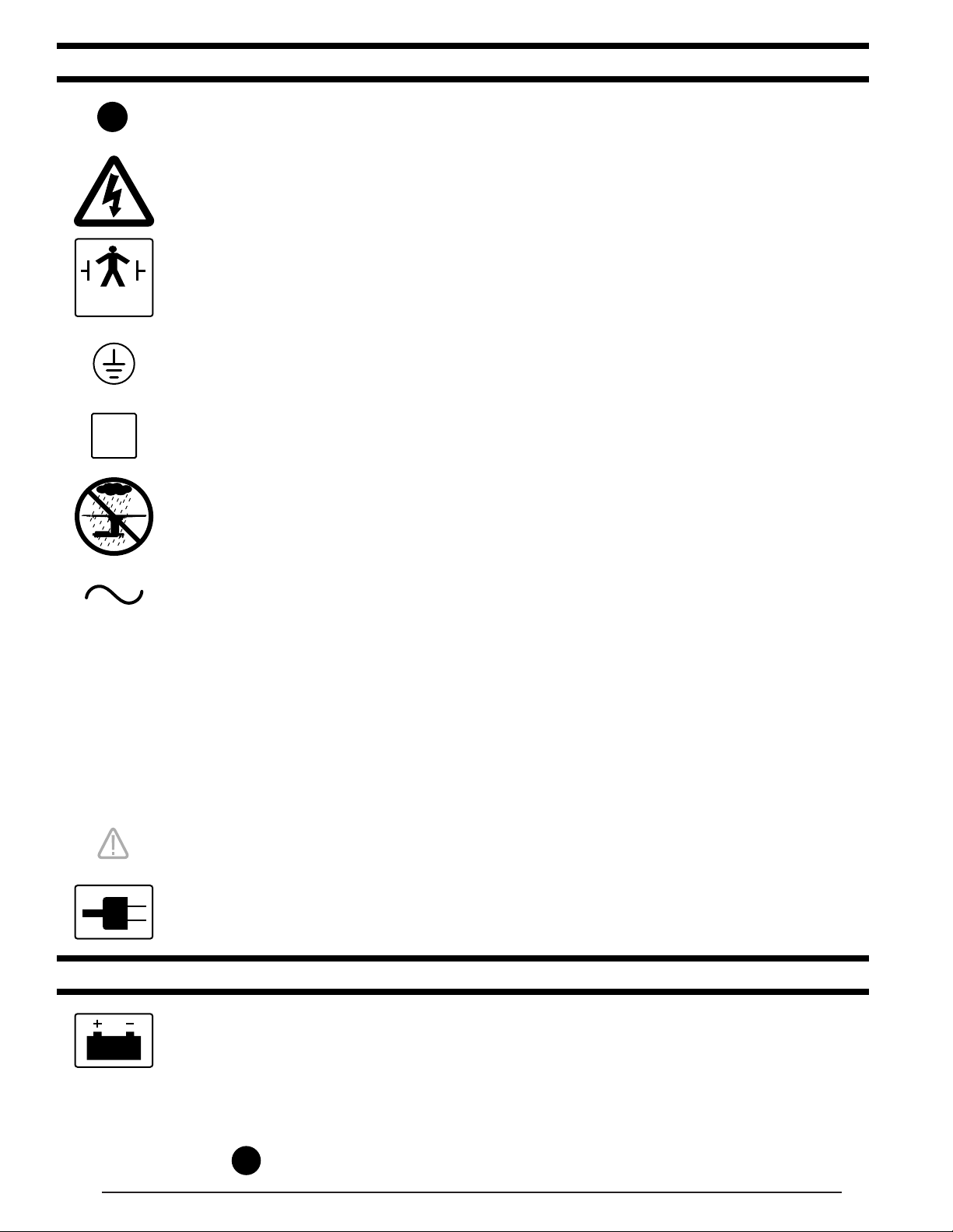
EQUIPMENT LABELS AND SPECIFICATIONS
10A
TYPE B
EQUIPMENT
N
FUSE TYPE 10 AMP, FAST ACTING (FA)
INDICATES DANGEROUS VOLTAGE, 120 V, 60 Hz
CLASS I DEFIBRILLATION PROOF, TYPE B EQUIPMENT- IPX4 RATED.
INTERNALLY POWERED EQUIPMENT
PROTECTIVE GROUNDING.
IN ORDER TO ENSURE PROPER GROUNDING RELIABILITY,
THIS TABLE MUST BE CONNECTED TO A PROPERLY GROUNDED
HOSPITAL GRADE OUTLET.
CONNECTION FOR NEUTRAL CONDUCTOR SUPPLIED
UNIT TO BE USED ONLY IN SPECIFIED ENVIRONMENTAL CONDITIONS
TEMPERATURE: 15˚ - 30˚ C (60˚ -85˚ F)
HUMIDITY: 30% - 60% RELATIVE HUMIDITY, NON CONDENSING
IPX4
V
A
HZ
AC VOLTAGE
ENCLOSURE CLASS
VOLTAGE RATING OF THE UNIT
AMPERAGE RATING OF THE UNIT
FREQUENCY OF THE UNIT
ATTENTION, CONSULT MANUAL FOR FURTHER INSTRUCTIONS.
INDICATES SPECIAL USER ATTENTION.
POWERED BY AC VOLTAGE
BATTERY MODELS
POWERED BY BATTERY
BATTERY TYPE: SEALED
LEAD ACID 12V, VALVE REGULATED
16AH, 10HR (530W/10MIN)
FUSE:
15A
2
15 AMP FAST ACTING INTERNAL FUSE

3500 Series General Purpose Surgical Table Specifications
60˚
90˚
9-1/2"
18-1/2" 25"
TOP VIEW
6"
79"
23"
21-3/4"
19-3/4"
26-45"*
8-1/2"
40-1/2"
SIDE VIEW END VIEW
Electrical Specifications
Power requirements
Current Leakage
Power Cord
15 feet w/hospital grade connector
120 VAC, 60Hz, 450 Watts
Less than 100 micro amps
(removeable on battery model)
ENTELA CERTIFIED
TO UL2601-1,
CAN/CSA601.1, IEC 60601-2-46
6"
19"
3

SPECIAL USER ATTENTION
The extreme positioning capabilities of the 3500
Series Table requires special attention for possible
interference points when using multiple function
positioning. As with the operation of any surgical
table, a certain amount of care should be exercised
to position the patient safely. Although the thick
pads and sheets substantially protect the patient,
pinch points, located at the joints of the top section
should always be considered. BE SURE THAT THE
ARMS, HANDS AND FINGERS OF THE PATIENT
AND THOSE OF THE OPERATING ROOM PERSONNEL ARE CLEAR OF ALL MOVING PARTS
BEFORE MOVING THE TABLE. Proper restraints
should always be used for patient safety.
Certain accessories such as the Uro-Drain Tray,
Armboards and X-Ray top can be damaged when
changing the position of the table top sections.
Always look first to see if a desired movement is
going to interfere with any accessories in use.
The operator has the ultimate responsibility of preventing damage to the table and surrounding equipment or possible injury to the patient or staff. In
general, common sense will dictate when there is a
potential hazard.
WARNING
Risk of electrical shock. Make sure
power cord is disconnected prior to accessing fuses.
NOTE
Activating any function button will activate the brake system. Using the TABLEUP function to set the brakes provides a
visual assurance that the brakes are
locked. As the brake cylinders are extending, the entire table will move slightly.
When the table top begins to elevate, the
brakes are fully locked.
WARNING
DO NOT unlock brakes when a patient is
on the table. An uneven patient weight
load may cause instability.
WARNING
Prior to operating the table, observe all
table caution labels and review the SPECIAL USER ATTENTION section in the
front of this manual.
The following precautions should be reviewed
by all personnel prior to operating the table.
A routine Instructional Program should be
implemented by the facility for proper usage
instructions for all personel that may operate
this table.
WARNING
Indicates a possibility of personal injury.
CAUTION
Indicates a possibility of damage to equipment.
NOTE
Indicates important facts or helpful hints.
WARNING
DO NOT use the table in the presence of
FLAMMABLE GASES (Flammable gases
are not commonly used in the U.S.)
NOTE
The main power switch can be placed in
the OFF position to completely deactivate all table functions if required during
certain procedures or in case of emergency.
NOTE
With an evenly distributed patient weight
load, all table positioning functions will
operate smoothly and quietly with a patient weight of up to 500 pounds.
WARNING
DO NOT unlock brakes when a patient
is on the table. An uneven patient
weight load may cause instability.
4

WARNING
To maximize patient safety, utilize
proper restraint methods during extreme
Trendelenburg positioning.
WARNING
To maximize patient safety, utilize
proper restraint methods during extreme
lateral tilt positioning.
NOTE
The Emergency Brake Release Valve
must be closed and tightened (clockwise) before activating any function.
•If the Emergency Brake Release Valve
has been operated, the UNLOCK button on the pendant control will have to
be pressed before brakes will lock
again.
NOTE
If the table top is slid toward the foot end,
the back section will not go below horizontal.
NOTE
To prevent damage to the kidney lift, a
safety interlock prevents the back section from going up more than 45° if the
kidney lift is not all the way down.
NOTE
If the leg section is positioned more than
45° below horizontal, the top will not
slide toward the head end.
NOTE
If the back section is positioned below
horizontal, the top will not slide toward
the foot end.
CAUTION
The Ieg section may hit the table base
or floor if both the leg and elevation
systems are placed in their full down
position.
NOTE
If the top is slid toward the head end, the
leg section will only go down 45°.
NOTE
When FLEX button is activated and if
the top is slid toward the foot end, the
back section will not go below horizontal.
NOTE
To prevent damage to the kidney lift, a
safety interlock prevents the kidney lift
from going up if the back section is 45°
above horizontal.
NOTE
Elevation, kidney lift, top slide and brake
system functions are not affected by
the return to level function.
WARNING
In the unlikely event that a procedure
requires the reversal of the patient on
the table top with the head section attached to the leg section, the patient
weight limit is reduced to 300 pounds.
NOTE
The leg section with the x-ray top + pad
attached weighs 31 lbs. It is recommended that the x-ray top and pad be
removed before detaching the leg section.
NOTE
•Turning the Main Power Switch ON will
change the table operation to 120 VAC
power regardless of the position of the
BATT button.
•If Battery operation is activated while
Main Power Switch is ON there will be
approximately a 4 second delay before
Battery operation activates.
NOTE
The power cord may be removed from
the table. The table will operate correctly on battery power with the power
cord connected to a wall outlet or disconnected.
NOTE
Battery Operation must be turned OFF
at the pendant control. It can not be
turned Off using the main power switch.
NOTE
If the table is stored for a period greater
than 6 months, the batteries should be
removed and stored in a dry, clean condition at a storage temperature of 68° F
(20° C). Batteries should be recharged
every 6 months of product storage.
5

NOTE
•When the red light starts to blink (indicating low power in battery) the table
will operate for approximately 5 continuous minutes, typically long enough
to use the table for the rest of the day.
•The charging system operates ONLY
when the table is in AC 120V mode.
NOTE
In battery mode, only the red indicator
light will be on. In AC 120V mode, both
the green indicator light and red indicator light will be on.
NOTE
The table can be operated on 120VAC
power while the battery is being recharged.
NOTE
The emergency back-up control
switches will function when the table is
operating on 120VAC power, battery
power, or turned off.
WARNING
The antistatic properties of the table are
dependent on the use of the original pad
set which was furnished with the table or
an alternate approved replacement.
WARNING
Certain accessories may limit weight
capacities. Check with your SKYTRON
representative.
NOTE
Always follow current AORN Journal
Guidelines to ensure proper cleaning
and disinfection procedure.
WARNING
Always follow OSHA blood-borne pathogens standards for protective clothing,
including gloves, masks and eye protection when cleaning the surgical table.
CAUTION
•The Emergency Release Valve must
be closed and tightened (clockwise)
before activating any hydraulic function.
•If the Emergency Brake Release Valve
has been operated, the UNLOCK button on the pendant control will have to
be pressed before brakes will lock
again.
WARNING
Consult manufacturer's instructions
when using high frequency surgical
equipment, cardiac defibrillator and cardiac defibrillator monitors.
WARNING
When an antistatic pathway is required,
the table has to be used on an antistatic
floor.
CAUTION
Thoroughly read and follow the
manufacturer's directions for all cleaning fluids. DO NOT use cleaners containing phenolics.
CAUTION
When using spray cleaners DO NOT
spray fluids directly into electrical receptacles or micro switches.
CAUTION
Before replacing pads on the table, make
sure the pads and all mating surfaces
are completely dry. Moisture trapped
between the pads and mating surfaces
may cause distortion of table tops.
6
 Loading...