

Page 1

Page 41
3
Item Part No. Description Qty.
4 18
7
5
6
8
3
21
9
7
8
3
10
27
28
29
30
31
32
33
35
36
37
12
13
11
7
22
38
23
39
8
16
40
41
42
17
43
24
44
Page 2

Page 3

Page 1
1. Top & Side Frame Assemblies-Head Section...........Page 4 2. Top & Side Frame Assemblies-Foot Section ......... Page 8
Item Part No. Description Qty.
3. Kidney Lift Assembly ...........................................Page 10 4. Side Frame & Hydraulic Cylinders ...................... Page 12
Page 4

Page 2
5. Trendelenburg & Lateral Tilt Cylinders ............. Page 16 6. Support Column Assembly ................................. Page 18
7. Electrical Components .....................................Page 22 8. Electrical Components, Battery Model ............ Page 26
Page 5

Page 3
9. Hydraulic Valves & Fittings ............................... Page 30 10. Electro / Mini Valve Assembly ..........................Page 34
Item Part No. Description Qty.
11. Base Assembly ................................................. Page 36
Page 6

INTRODUCTION
This manual contains the exploded views and replacement parts lists for the service-
able components of the SKYTRON Model 6600 Surgical Table.
Each serviceable part in these exploded views is identified by a reference number.
Use this number to locate necessary part information in the parts list adjacent to the
exploded view.
Always use the complete SKYTRON part number and description when ordering
replacement parts.
Always use the complete table serial number (S.N.) when ordering replacement
parts.
Special Tools and Maintenance Items listed on page 38.
Abbreviations
As Required .......................................... A/R
Optional................................................... opt
Serial Number ....................................... S.N.
All Later S.N.'s ......................................... &L
All Prior S.N.'s .......................................... &P
Not Shown............................................... NS
REV. 10/03
Although current at the time of publication, SKYTRON's policy of continuous development makes this
manual subject to change without notice.
Page 7

Page 4
1. TOP & SIDE FRAME ASSEMBLIES -HEAD SECTION
1
4
2
55
26
25
24
23
19
18
7
17
6
8
9
10
12
3
11
13
27
5
22
28
20
16
21
30
14
15
29
45
54
31
32
4
21
53
26
48
51
41
52
45
27
50
49
21
45
38
39
36
40
33
42
47
43
46
34
35
37
17
44
6600.0802.001
Page 8

1. TOP & SIDE FRAME ASSEMBLIES-HEAD SECTION
Item Part No. Description Qty.
1-010-22-P PAD SET..................................................................................................................... opt
1 1-010-06-8P PAD, back/seat section ...............................................................................................opt
2 D3-033-01 TOP, back section ........................................................................................................ 1
3 D3-033-03 TOP, seat section ..........................................................................................................1
4 D3-010-19 SCREW, phillips hd., ...................................................................................................A/R
5 D3-032-36 CAP, back section axis..................................................................................................2
6 D3-035-41 GEAR, spur, back section .............................................................................................2
7 D6-010-10-1 SCREW, set, M6 x 10....................................................................................................2
8 D6-034-01 PIN, spur gear, tapered, M7 x 35 ..................................................................................2
9 D3-032-31 BUSHING, back section ................................................................................................2
10 D3-034-06 LEVER, AXIS, back/seat section, right..........................................................................1
D3-034-07 LEVER, AXIS, back/seat section, left............................................................................1
11 D6-010-50 SCREW, set, M6 x 15....................................................................................................2
12 D3-034-08 FRAME, side, right ........................................................................................................1
D3-034-09 FRAME, side, left, .........................................................................................................1
13 D3-034-42 NAMEPLATE, label, 6600 .............................................................................................2
D3-034-44 NAMEPLATE, label, 6600B...........................................................................................2
14 D3-032-37 AXIS, back section ........................................................................................................2
15 D6-032-28 BOLT, allen ...................................................................................................................2
16 D3-034-12 SIDE RAIL, back section, right ......................................................................................1
D3-034-13 SIDE RAIL, back section, left ........................................................................................1
17 D3-032-34 STUD, side rail mount, M8x45.......................................................................................6
D3-032-34-1 STUD, side rail mount, long (with collar) .......................................................................6
18 D6-010-83 BOLT, allen, M5 x 30.....................................................................................................2
19 D6-010-76 NUT, M5 ........................................................................................................................2
20 D3-034-14 LEVER, release............................................................................................................2
21 D3-010-01 COLLAR, side rail.........................................................................................................12
22 D3-034-16 FRAME, back section, right...........................................................................................1
D3-034-17 FRAME, back section, left .............................................................................................1
23 D3-032-51 SPRING, back section, right..........................................................................................1
D3-032-51-1 SPRING, back section, left ............................................................................................1
24 D6-032-37 PIN, roll, M4 x 30 ...........................................................................................................2
25 D6-010-65-1 BOLT, allen, M5 x 35 (plated) .......................................................................................2
26 D6-010-09-1 WASHER, lock, M8 .....................................................................................................A/R
27 D6-010-13-1 NUT, M8 (plated)......................................................................................................... 14
D6-032-34 NUT, w/lockwasher .....................................................................................................A/R
28 D3-010-17 KNOB, retaining, back section ......................................................................................2
29 D3-010-43 STOP, rail, large ............................................................................................................2
30 D3-010-41 PIN, rail stop ..................................................................................................................2
31 1-010-06-1P PAD, head section....................................................................................................... opt
32 D3-032-04 TOP, head section.........................................................................................................1
33 5-010-01-8 BUSHING, x-ray top ....................................................................................................A/R
34 D4-010-14 O-RING, P-12 ............................................................................................................... 2
35 D3-010-31-1 SHAFT, extension, head section (roll pin) ................................................................... 2
36 D6-050-33 PIN, roll, M5 x 20 .........................................................................................................A/R
37 D3-032-80 GEAR/TRUNNION, right ...............................................................................................1
D3-032-81 GEAR/TRUNNION, left..................................................................................................1
38 D6-010-38-1 BOLT, allen, M6x15 (plated) .........................................................................................2
Page 5
Page 9

Page 6
1. TOP & SIDE FRAME ASSEMBLIES-HEAD SECTION (CONTINUED)
1
4
2
55
26
25
24
23
19
18
7
17
6
8
9
10
12
3
11
13
27
5
22
28
20
16
21
30
14
15
29
45
54
31
32
4
21
53
26
48
51
41
52
45
27
50
49
21
45
38
39
36
40
33
42
47
43
46
34
35
37
17
44
6600.0802.001
Page 10

1. TOP & SIDE FRAME ASSEMBLIES-HEAD SECTION (CONTINUED)
Item Part No. Description Qty.
39 D6-010-40-1 WASHER, lock, M6 (plated) ..........................................................................................2
40 D6-010-41-1 SCREW, set, M8x15 (plated) ........................................................................................2
41 D3-032-05 FRAME, head section ...................................................................................................1
42 D3-034-22 BUSHING, head section................................................................................................2
43 D6-010-53-1 BOLT, allen M8x20........................................................................................................2
44 D3-032-10 RAIL, side, head section ...............................................................................................2
45 D3-032-35 STUD, side rail mount, M8 x 40.....................................................................................4
D3-032-34-2 STUD, side rail mount, short (with collar) ......................................................................4
46 D6-010-38 BOLT, allen, M6 x 15.....................................................................................................4
47 D6-010-40 WASHER, lock, M6 .......................................................................................................4
48 D3-032-33 RAIL, accessory ............................................................................................................1
49 D3-010-27 PLUNGER, release .......................................................................................................2
50 D3-010-26 SPRING, release ...........................................................................................................2
51 D3-032-40 BLOCK, bearing ............................................................................................................2
52 D6-010-11 SCREW, set, M5 x 8 (plated) ........................................................................................2
53 D6-010-08 ACORN NUT .................................................................................................................2
54 D3-010-24 RELEASE BAR, head section .......................................................................................1
55 D3-010-18-H VELCRO, hook ............................................................................................................A/R
Page 7
Page 11

Page 8
2. TOP & SIDE FRAME ASSEMBLIES-FOOT SECTION
1
2
4
25
3
5
13
18
10
6
7
8
9
18
14
23
7
8
21
11
24
19
26
27
28
15
17
16
13
12
18
22
14
20
6600.0802.002
Page 12

2. TOP & SIDE FRAME ASSEMBLIES-FOOT SECTION
Item Part No. Description Qty.
1-010-22-P PAD SET ..................................................................................................................... opt
1 1-010-06-7P PAD, foot/leg section................................................................................................... opt
2 D3-033-02 TOP, foot/leg section.................................................................................................... 1
3 D3-010-19 SCREW, phillips hd., ...................................................................................................A/R
4 5-010-01-8 BUSHING, x-ray top ....................................................................................................A/R
5 D3-034-24 FRAME, foot/leg section (right) .................................................................................... 1
D3-034-25 FRAME, foot/leg section (left) ...................................................................................... 1
6 D6-031-01 KNOB, retaining, foot/leg section ..................................................................................2
7 D6-010-13-1 NUT, M8 (plated) ..........................................................................................................12
D6-032-34 NUT, w/lockwasher .....................................................................................................A/R
8 D6-010-09-1 WASHER, lock, M8 .....................................................................................................A/R
9 D3-034-18 SPRING, foot/leg section (right) ................................................................................... 1
D3-034-19 SPRING, foot/leg section (left) ..................................................................................... 1
10 D6-010-65-1 BOLT, allen, M5 x 35 (plated) ......................................................................................2
11 D6-034-02 PIN, roll, M4 x 30 .......................................................................................................... 2
12 D3-010-01 COLLAR, side rail........................................................................................................ 12
13 D3-010-43 STOP, rail, large ........................................................................................................... 4
14 D3-010-41 PIN, rail stop ................................................................................................................. 4
15 D6-010-76 NUT, M5 ....................................................................................................................... 2
16 D6-010-83 BOLT, allen, M5 x 30.................................................................................................... 4
17 D3-032-15 RAIL, side, foot/leg section, right...................................................................................1
D3-032-16 RAIL, side, foot/leg section, left.....................................................................................1
18 D3-032-34 STUD, side rail mount, M8x45......................................................................................10
D3-032-34-1 STUD, side rail mount, long (with collar) ......................................................................10
19 D3-032-35 STUD, side rail mount, M8 x 40.....................................................................................2
D3-032-34-2 STUD, side rail mount, short (with collar) ......................................................................2
20 D3-034-14-1 LEVER, release ............................................................................................................2
21 D3-034-31 LEVER, axis, foot/leg section (right)..............................................................................1
D3-034-32 LEVER, axis, foot/leg section (left)................................................................................1
22 D3-034-33 RAIL, side, seat section, right........................................................................................1
D3-034-34 RAIL, side, seat section, left..........................................................................................1
D3-010-41 •PIN, rail stop, M4 x 8....................................................................................................1
23 D6-010-50 SCREW, set, M6 x 15....................................................................................................4
24 D3-030-05 AXIS, foot/leg section ....................................................................................................2
25 D3-010-18-H VELCRO, hook ............................................................................................................A/R
26 D3-034-46 STOP, rubber ................................................................................................................2
27 D3-034-47 HINGE ...........................................................................................................................2
28 D3-034-48 PIN.................................................................................................................................2
Page 9
Page 13
Page 10
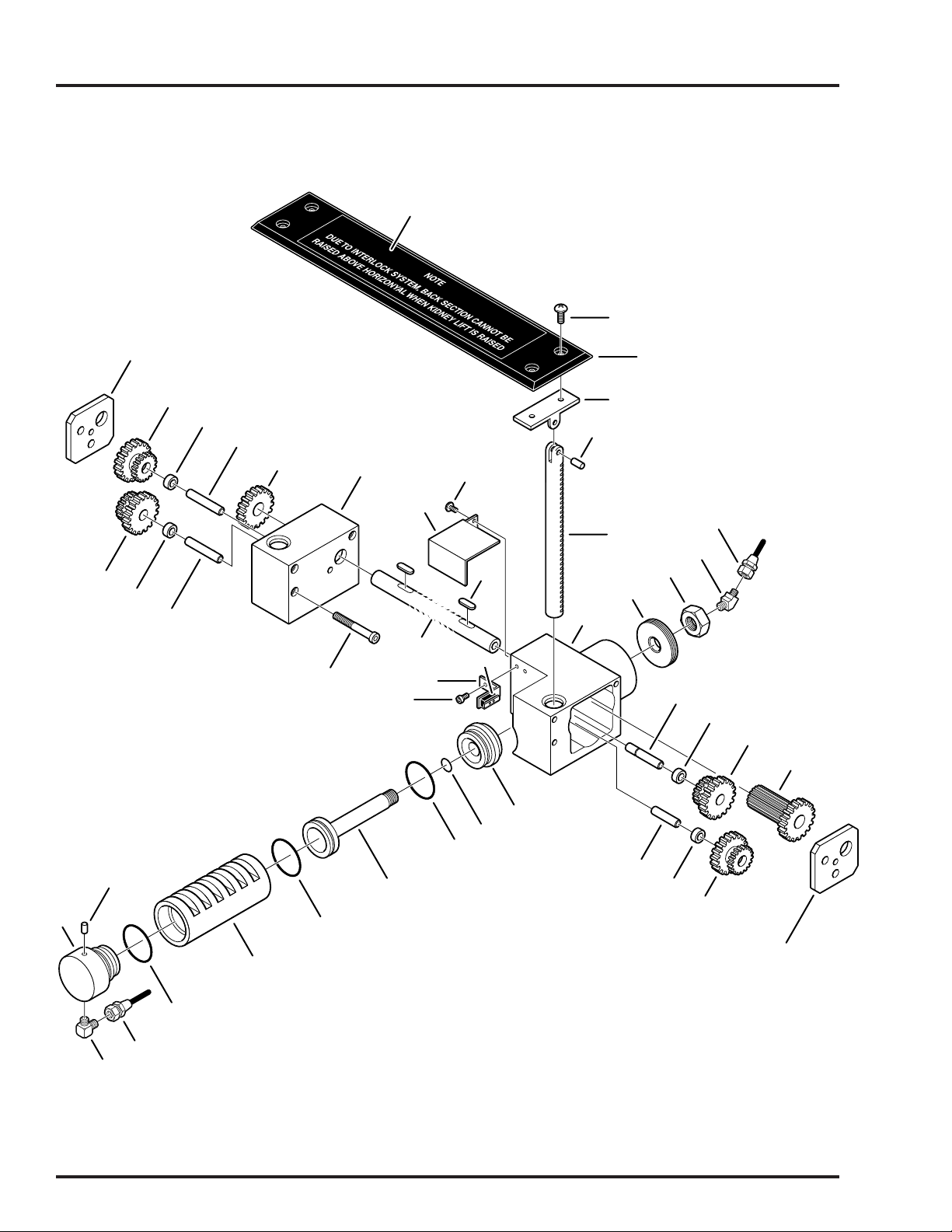
3. KIDNEY LIFT ASSEMBLY
1
2
24
23
25
24
26
25
26
27
29
28
34
31
33
35
32
30
36
3
4
5
40
6
39
9
8
7
10
12
13
14
21
37
22
38
18
20
18
19
16
17
18
11
12
13
15
6600.0802.003
Page 14

3. KIDNEY LIFT ASSEMBLY
Item Part No. Description Qty.
1 D6-032-43 DECAL, kidney bridge ...................................................................................................1
2 D5-035-42-1 SCREW, round head, M5 x 10 ......................................................................................4
3 D5-035-42 TOP, kidney lift ..............................................................................................................1
4 D3-032-39-1 PIVOT, kidney lift, flat....................................................................................................2
5 D6-031-24 PIN, roll, M5 x 12 ...........................................................................................................2
6 D3-032-52 SHAFT, kidney lift..........................................................................................................2
-- D4-032-43 CYLINDER ASSEMBLY, kidney lift ...............................................................................1
7 D4-034-01 •HOUSING, cylinder assembly ......................................................................................1
8 D4-032-88 •END CAP .....................................................................................................................1
9 D4-032-89 •NUT ..............................................................................................................................1
10 D4-032-35 •PIN ...............................................................................................................................1
11 D4-032-34 •PIN ...............................................................................................................................1
12 D4-032-30 •BUSHING .....................................................................................................................2
13 D4-032-32 •GEAR, dual ..................................................................................................................2
14 D4-032-36 •GEAR ...........................................................................................................................1
15 D4-032-29 •COVER.........................................................................................................................1
16 D4-034-02 •RETAINER ...................................................................................................................1
17 D4-041-15 •O-RING, P-18...............................................................................................................1
18 D4-050-01 •O-RING, P-29...............................................................................................................3
19 D4-034-03 •PISTON ........................................................................................................................1
20 D4-034-04 •CYLINDER ...................................................................................................................1
21 D4-034-05 •END CAP .....................................................................................................................1
22 D4-034-06 •PIN ...............................................................................................................................1
-- D4-032-33 GEAR BOX ASSEMBLY ...............................................................................................1
23 D4-032-29 •COVER.........................................................................................................................1
24 D4-032-32 •GEAR, dual ..................................................................................................................2
25 D4-032-30 •BUSHING .....................................................................................................................2
26 D4-032-34 •PIN ...............................................................................................................................2
27 D4-032-31 •GEAR ...........................................................................................................................1
28 D4-034-07 •HOUSING, gear box assembly ....................................................................................1
29 D6-010-65 BOLT, allen, M5 x 35.....................................................................................................6
30 D4-032-37 KEY ...............................................................................................................................2
31 D4-032-38 COVER, micro-switch....................................................................................................1
32 D6-032-26 SCREW, phillips hd. ......................................................................................................2
33 D4-032-40 SHAFT, drive .................................................................................................................1
34 D6-032-27 BOLT, allen ...................................................................................................................2
35 D4-032-39 BRACKET, micro-switch ...............................................................................................1
36 D5-032-15 MICRO-SWITCH ...........................................................................................................1
37 D4-010-29 FITTING, hydraulic, 90° elbow ......................................................................................1
38 D4-032-53 HOSE, flexible, 600mm .................................................................................................1
39 D4-010-30 FITTING, hydraulic, 45° elbow ......................................................................................1
40 D4-032-54 HOSE, flexible, 520mm .................................................................................................1
Page 11
Page 15

Page 12
4. SIDE FRAME & HYDRAULIC CYLINDERS
40
21
20
32
22
31
20
30
16
29
65 66
14
24
28
27
19
10
26
24
15
16
10
13
25
12
11
10
24
44
37
38
9
23
62
15
17
1
18
2
8
3
4
5
6
7
41
40
43
42
39
40
64
33
63
35
36
54
34
58 57
59
60
61
55
48
45
51
50
53
49
47
52
46
62
35
56
55
6600.0802.004
Page 16

4. SIDE FRAME & HYDRAULIC CYLINDERS
Item Part No. Description Qty.
1 D6-031-19 CLEVIS......................................................................................................................... 2
2 D6-010-34 SCREW, set, M6 x 6......................................................................................................2
-- D4-032-02-A CYLINDER ASSEMBLY, foot/leg section, S.N. A0001 & L ...........................................2
-- D4-032-02 CYLINDER ASSEMBLY, (prior to S.N. A0001) .............................................................2
3 ----- •RAM (not available separately) ...................................................................................1
4 D4-010-03 •O-RING, P-25 ...............................................................................................................1
5 D6-010-55 •NUT, M8 .......................................................................................................................4
6 ----- •HEAD CAP (not available separately)..........................................................................1
7 D4-010-48 •STUD, cylinder .............................................................................................................4
8 D4-010-02 •O-RING, P-14 ...............................................................................................................1
9 ----- •PISTON (not available separately)...............................................................................1
10 D4-010-54 •O-RING, P-34...............................................................................................................3
11 D4-010-42 •WASHER, lock, M10 ....................................................................................................1
12 D6-010-43 •NUT, M10 .....................................................................................................................1
13 D4-034-11 •CYLINDER ...................................................................................................................1
14 ----- •TAIL CAP (not available separately)............................................................................1
15 D4-010-29 FITTING, hydraulic, 90° elbow ......................................................................................4
16 D4-032-05 HOSE, flexible, foot/leg section piston, left ...................................................................1
D4-032-06 HOSE, flexible, foot/leg section piston, right .................................................................1
17 D6-030-03 PIN, clevis .....................................................................................................................2
18 D6-030-01 CIRCLIP ........................................................................................................................2
19 D3-034-09 FRAME, side, left ..........................................................................................................1
D3-034-08 FRAME, side, right ........................................................................................................1
20 D3-010-37 AXIS, eccentric cam ......................................................................................................4
21 D3-010-38 AXIS, eccentric cam ......................................................................................................2
22 D3-010-36 BEARING, support ........................................................................................................2
-- D4-032-01-A CYLINDER ASSEMBLY, back section S.N. A0001 & L ................................................2
-- D4-032-01 CYLINDER ASSEMBLY, (prior to S.N. A0001) .............................................................2
23 ----- •TAIL CAP (not available separately)............................................................................1
24 D4-010-04 •O-RING, P-44...............................................................................................................3
25 D4-034-14 •CYLINDER ...................................................................................................................1
26 D6-010-43 •NUT, M10 .....................................................................................................................1
27 D6-010-42 •WASHER, lock, M10 ....................................................................................................1
28 ----- •PISTON (not available separately)...............................................................................1
29 D4-010-02 •O-RING, P-14...............................................................................................................1
30 ----- •HEAD CAP (not available separately)..........................................................................1
31 D4-010-03 •O-RING, P-25...............................................................................................................1
32 ----- •RAM (not available separately)...................................................................................1
33 D6-010-55 •NUT, M8 .......................................................................................................................4
34 D4-010-48 •STUD, cylinder .............................................................................................................4
35 D4-031-06 FITTING, flexible hose ................................................................................................A/R
36 D4-032-09 HOSE, flexible, back section ram, left .......................................................................... 1
D4-032-10 HOSE, flexible, back section ram, right........................................................................ 1
37 D4-010-30 FITTING, hydraulic, 45° elbow ..................................................................................... 2
38 D4-032-07 HOSE, flexible, back section piston, left ...................................................................... 1
D4-032-08 HOSE, flexible, back section piston, right .................................................................... 1
39 D3-034-38 BRACE, side frame, left ............................................................................................... 1
D3-034-39 BRACE, side frame, right ............................................................................................. 1
40 D6-010-34 SCREW, set, M6x6......................................................................................................A/R
Page 13
Page 17

Page 14
4. SIDE FRAME & HYDRAULIC CYLINDERS (CONTINUED)
40
21
20
32
22
31
20
30
16
29
65 66
14
24
28
27
19
10
26
24
15
16
10
13
25
12
11
10
24
44
37
38
9
23
62
15
17
1
18
2
8
3
4
5
6
7
41
40
43
42
39
40
64
33
63
35
36
54
34
58 57
59
60
61
55
48
45
51
50
53
49
47
52
46
62
35
56
55
6600.0802.004
Page 18

4. SIDE FRAME & HYDRAULIC CYLINDERS (CONTINUED)
Item Part No. Description Qty.
41 D6-010-17-1 BOLT, allen, M8 x 15 (plated) .......................................................................................8
42 D3-034-40 COVER, micro-switch, left.............................................................................................1
D3-034-41 COVER, micro-switch, right...........................................................................................1
43 D6-010-80 SCREW, phillips hd., M3 x 6 .........................................................................................6
44 D6-010-70-1 BOLT, allen, M5 x 10 (plated) .......................................................................................4
45 D2-032-04 COVER, flexible hose....................................................................................................1
46 D2-032-05 END CAP, cover, right...................................................................................................1
D2-032-05-A END CAP, cover, left .....................................................................................................1
47 D2-010-38 STAND-OFF, cover .......................................................................................................4
48 D6-010-71-1 BOLT, allen, M10 x 40 (plated) ...................................................................................A/R
49 D6-050-36 BOLT, allen, M5 x 8...................................................................................................... 4
50 D6-034-04 WASHER, flat M5 ......................................................................................................... 4
51 D2-032-48 RAMP, micro-switch ..................................................................................................... 2
52 D2-032-32 GEAR, Trendelenburg, S.N. A0001 & L ........................................................................1
D2-032-02 GEAR, Trendelenburg, (prior to S.N. A0001) ................................................................1
53 D6-032-01 PIN, tapered ..................................................................................................................2
54 D3-034-36 INNER CASTING, side frame, left.................................................................................1
D3-034-37 INNER CASTING, side frame, right...............................................................................1
55 D2-032-01 BEARING, Trendelenburg axis ....................................................................................2
56 D3-032-03 AXIS, Trendelenburg ....................................................................................................1
57 D6-010-07 PIN, tapered, M12 x 90..................................................................................................1
58 D6-010-10-2 BOLT, allen, M10 x 45 (plated) ...................................................................................A/R
59 ----- GASKET, connector (part of D5-034-06) ......................................................................1
60 D5-034-06 CONNECTOR, 7-pin, female.........................................................................................1
61 D6-034-05 SCREW, phillips, M6 x 7 (plated) ..................................................................................4
62 D4-032-03 HOSE, flexible, foot/leg section ram, left.......................................................................1
D4-032-04 HOSE, flexible, foot/leg section ram, right.....................................................................1
63 D3-032-42 BRACKET, micro-switch mounting................................................................................2
64 D5-032-15 MICRO-SWITCH ...........................................................................................................2
65 D3-032-43 BRACKET, micro-switch ...............................................................................................2
66 D5-032-17 MICRO-SWITCH ...........................................................................................................2
Page 15
Page 19

Page 16
5. TRENDELENBURG & LATERAL TILT CYLINDERS
13
14
15
16
18
17
10
20
19
21
22
11
12
8
6
5
4
3
7
9
2
1
25
24
30
26
31
28
29
20
27
16
17
23
17
33
21
18
34
40
41
36
37
38
17
39
35
34
42
43
44
32
45
47
46
6600.0802.005
Page 20

5. TRENDELENBURG & LATERAL TILT CYLINDERS
Item Part No. Description Qty.
1 D6-032-48 BOLT, button head, M8 x 25 .........................................................................................8
D6-010-33-1 BOLT, allen, M8 x 25, plated .........................................................................................8
2 D2-032-69 CAP, lateral tilt, right (prior to S.N. A0001)....................................................................1
D2-032-70 CAP, lateral tilt, left (prior to S.N. A0001) ......................................................................1
3 D4-032-79 O-RING, S-55 ................................................................................................................2
4 D4-060-24 O-RING, P-49 ................................................................................................................4
5 D2-032-08-1 PISTON, lateral tilt.........................................................................................................2
6 D2-032-07-1 ROD, piston ...................................................................................................................2
7 D4-010-52 O-RING, P-4 ................................................................................................................A/R
8 D2-034-01 SLEEVE ........................................................................................................................2
9 D6-010-16-1 SCREW, phillips hd., M5 x 6, stainless .........................................................................2
10 D2-032-10 PLATE, inspection cover ...............................................................................................1
D2-032-47 PLATE, inspection cover, battery model .......................................................................1
11 D4-010-01 O-RING, P-8 ..................................................................................................................2
12 D6-010-45 BOLT, allen, M10 x 30...................................................................................................3
-- D2-032-68-A HOUSING & CAP ASSEMBLY, lateral tilt, S.N. A0001 & L ..........................................1
13 D2-032-68 HOUSING, lateral tilt , (prior to S.N. A0001) .................................................................1
14 D6-010-30 BOLT, allen, M6 x 20.....................................................................................................6
15 D2-034-02 CAP, tail ........................................................................................................................1
16 D4-032-80 O-RING, S-70 ................................................................................................................2
17 D4-010-06 O-RING, P-60 ................................................................................................................4
18 D2-032-14 BUSHING, graphite .......................................................................................................2
19 D2-032-15 PIVOT BLOCK, lateral tilt, tail .......................................................................................1
20 D4-010-07 O-RING, P-95 ................................................................................................................4
21 D4-010-32 PACKING, copper .......................................................................................................A/R
22 D4-010-99 FITTING, plumbing ......................................................................................................A/R
23 D4-010-29 FITTING, hydraulic, 90° elbow ....................................................................................A/R
24 D6-034-06 SCREW, phillips, M4 x5 (plated) ...................................................................................4
25 D2-034-03 COVER, pendant control connector ..............................................................................1
26 D6-060-29 SCREW, phillips hd., M5 x 8 .........................................................................................3
27 D2-034-04 COVER, Trendelenburg cylinder..................................................................................1
28 D6-010-30-1 BOLT, allen, M6 x 20 (plated) .......................................................................................6
29 D2-032-19 CAP, head, trend. cyl. ...................................................................................................1
30 D5-032-15 MICRO-SWITCH, lateral tilt...........................................................................................2
31 D2-032-45 BRACKET, micro-switch ...............................................................................................2
32 D4-010-33 FITTING, flexible hose, long........................................................................................A/R
33 D2-032-18 PIVOT BLOCK, lateral tilt, head ....................................................................................1
34 D2-032-31 PISTON, Trendelenburg................................................................................................2
35 D2-032-33 HOUSING, Trendelenburg ............................................................................................1
36 D2-032-46 BRACKET, micro-switch ...............................................................................................2
37 D5-032-16 MICRO-SWITCH, Trendelenburg ..................................................................................2
D2-032-66 ACTUATOR, micro-switch.............................................................................................1
38 D6-010-29 BOLT, allen, M10 x 85...................................................................................................4
39 D2-032-16 CASTING, trend. bearing ..............................................................................................1
40 D6-010-21 WASHER, lock, M12 .....................................................................................................2
41 D6-011-06 BOLT, allen, M12 x 45...................................................................................................2
42 D4-010-30 FITTING, hydraulic, 45° elbow ....................................................................................A/R
43 D4-031-06 FITTING, flexible hose ................................................................................................A/R
44 D6-011-07 NUT, M12 ......................................................................................................................2
45 D2-032-71 BAR, hose guide ...........................................................................................................2
46 D2-010-45 HOLDER, hose..............................................................................................................2
47 D6-011-08 BOLT, allen, M5 x 18.....................................................................................................2
Page 17
Page 21

Page 18
17
6. SUPPORT COLUMN ASSEMBLY
16
2
30
4
1
3
31
4
32
5
20
33
34
35
6
8
4
3
4
10
9
22
7
23
24
11
36
37
38
39
40
25
21
41
42
43
10
4
8
9
3
4
12
14
15
13
10
26
8
9
28
27
46
18
19
44
45
47
48
49
29
50
6600.0802.006
Page 22

6. SUPPORT COLUMN ASSEMBLY
Item Part No. Description Qty.
-- D2-034-08 SLIDER ASSEMBLY .....................................................................................................1
1 D2-032-37 •SLIDER SECTION, #1 .................................................................................................1
2 D6-032-23 •SET SCREW, M10 x 20 ...............................................................................................1
3 D2-032-27 •KEY, slider ...................................................................................................................3
4 D2-034-06 •BEARING ASSEMBLY, roller .......................................................................................6
5 D2-032-28 •RING, elevation clamp .................................................................................................1
D6-032-40 •BALL, steel, 4mm .......................................................................................................A/R
6 D2-032-38 •STOPPER, rotation ..................................................................................................... 1
7 D2-034-09 •SLIDER SECTION, #2 ................................................................................................ 1
8 D6-034-17 •SCREW, set ................................................................................................................ 6
9 D2-010-14 •BOSS, slider................................................................................................................ 3
10 D6-050-38 •BOLT, allen, M8 x 10 .................................................................................................. 6
11 D2-034-10 •STOPPER, slider section #1 ....................................................................................... 1
12 D2-034-11 •SLIDER SECTION, #3 ................................................................................................ 1
13 D2-034-12 •STOPPER, slider section #2 ....................................................................................... 1
14 D2-034-13 •SLIDER, main ............................................................................................................. 1
15 D2-034-14 •STOPPER, slider section #3 ....................................................................................... 1
16 D6-050-36-1 BOLT, allen, M5 x 8...................................................................................................... 1
17 D2-010-21 PLATE, head, elevation cylinder .................................................................................. 1
18 D6-010-22 BOLT, allen, M12 x 35.................................................................................................. 3
19 D6-010-21 WASHER, lock, M12 ....................................................................................................3
20 D2-032-22 SHROUD, elevation, middle ..........................................................................................1
21 D2-032-21 SHROUD, elevation, outer ............................................................................................1
22 D6-010-19 SCREW, phillips hd., M5 x 10 (stainless)......................................................................3
23 D2-034-05 HANDLE, table top locking ............................................................................................1
24 D6-034-18 LABEL, top rotation handle ...........................................................................................1
25 D6-034-19 LABEL, table top warning ..............................................................................................1
26 D2-034-17 SHROUD, elevation, inner.............................................................................................1
27 D6-010-49 SCREW, M5 x 12 ..........................................................................................................4
28 D2-034-07 GASKET ........................................................................................................................1
29 D4-010-31 FITTING, flexible hose ..................................................................................................1
-- D4-034-18-A ELEVATION CYL. ASSEMBLY, S.N. A0001 & L ..........................................................1
-- D4-034-18 ELEVATION CYL. ASSEMBLY, (prior to S.N. A0001) ..................................................1
30 D4-034-43 •CUSHION, rubber ........................................................................................................1
31 D4-034-34 •CAP ..............................................................................................................................1
32 D4-034-35 •ROD, primary piston.....................................................................................................1
33 D4-010-56 •O-RING, P-10A ............................................................................................................1
34 D4-034-36 •PISTON, primary..........................................................................................................1
35 D4-034-42 •SPACER ......................................................................................................................1
36 D4-050-01 •O-RING, P-29...............................................................................................................1
37 D6-010-42 •WASHER, lock, M10 ....................................................................................................1
38 D6-010-56 •NUT, M10 .....................................................................................................................1
39 D4-034-37 •CAP, elevation tube .....................................................................................................1
40 D4-034-38 •TUBE, secondary piston ..............................................................................................1
41 D4-034-19 •O-RING, P-31...............................................................................................................1
42 D4-034-39 •PISTON, secondary .....................................................................................................1
43 D4-010-53 •O-RING, P-36...............................................................................................................1
44 D4-034-40 •TUBE, elevation cylinder..............................................................................................1
45 D4-040-40 •O-RING, P-39...............................................................................................................1
Page 19
Page 23

Page 20
17
6. SUPPORT COLUMN ASSEMBLY (CONTINUED)
16
2
30
4
1
3
31
4
32
5
20
33
34
35
6
8
4
3
4
10
9
22
7
23
24
11
36
37
38
39
40
25
21
41
42
43
10
4
8
9
3
4
12
14
15
13
10
26
8
9
28
27
46
18
19
44
45
47
48
49
29
50
6600.0802.006
Page 24

6. SUPPORT COLUMN ASSEMBLY (CONTINUED)
Item Part No. Description Qty.
46 D6-032-24 •BOLT, M8 x 20 .............................................................................................................1
47 D6-032-25 •BOLT, M8 x 30 .............................................................................................................1
48 D2-034-18 •CUSHION, rubber dropping .........................................................................................1
49 D4-034-41 •SAUCER, elevation cylinder ........................................................................................1
50 -- HOSE, flexible ...............................................................................................................1
Page 21
Page 25

Page 22
7. ELECTRICAL COMPONENTS
1
4
2
3
5
8
9
13
14
15
19
40
41
42
39
29
32
38
30
37
33
36
34
43
31
6
28
7
27
10
11
16
20
12
17
26
18
25
7
35
24
23
21
44
22
21
45
27
28
47
46
6600.0802.007
Page 26

7. ELECTRICAL COMPONENTS
Item Part No. Description Qty.
D5-034-01 PENDANT CONTROL ASSEMBLY ..............................................................................1
1 D6-032-33 •SCREW, pendant hook, M4 x 12 .................................................................................3
2 D5-034-07 •HOOK, pendant ............................................................................................................1
3 D5-034-08 •PLATE, pendant hook ..................................................................................................1
4 ----- •INSERT, pendant hook (part of D5-034-07).................................................................1
5 D5-034-10 •BACK PLATE ...............................................................................................................1
6 D6-034-07 •PLUG, rubber ...............................................................................................................8
7 D6-010-79-1 •SCREW, M3x5 (plated) ..............................................................................................A/R
8 D5-034-11 •HOUSING ................................................................................................................... 1
9 D5-034-12 •CONNECTOR ASSY., 7-pin, female........................................................................... 1
10 ----- O-RING, connector assembly .......................................................................................1
11 D6-034-08 •NUT, M3 (plated)........................................................................................................A/R
12 D6-034-09 •WASHER, M3 ............................................................................................................A/R
13 D5-034-13 •CIRCUIT BOARD ........................................................................................................ 1
14 D5-034-14 •PLATE, circuit board mounting ................................................................................... 1
15 D6-034-15 •COVER, circuit board mounting plate ......................................................................... 1
16 D6-034-10 •BUTTON ....................................................................................................................A/R
17 D6-034-11 •STAND-OFF...............................................................................................................A/R
18 D6-034-12 •STAND-OFF...............................................................................................................A/R
19 D5-034-16 •FACE PLATE, pendant control ................................................................................... 1
20 D5-034-17 •COVER, rubber ........................................................................................................... 1
21 D5-034-18 •CORD ASSEMBLY ..................................................................................................... 1
22 D5-034-06 CONNECTOR, 7-pin, female.........................................................................................1
23 D5-034-19-A CONNECTOR, 6-pin, male, S.N. A0001 & L .................................................................1
D5-034-19 CONNECTOR, 6-pin, male............................................................................................1
24 D5-034-20-A CONNECTOR, 6-pin, female, S.N. A0001 & L ..............................................................1
D5-034-20 CONNECTOR, 6-pin, female.........................................................................................1
25 D5-034-21-A CONNECTOR, 15-pin, male, S.N. A0001 & L ...............................................................1
D5-034-21 CONNECTOR, 15-pin, male..........................................................................................1
26 D5-034-22-A CONNECTOR, 15-pin, female, S.N. A0001 & L ............................................................1
D5-034-22 CONNECTOR, 15-pin, female.......................................................................................1
27 D5-030-03 CONNECTOR, 2-pin, female.......................................................................................A/R
28 D5-030-02 CONNECTOR, 2-pin, male..........................................................................................A/R
29 D5-034-23 CONNECTOR, 4-pin, female, (CN-2B) .........................................................................1
30 D5-034-24 CONNECTOR, 16-pin, female, (CN-2A) .......................................................................1
31 D5-034-25 CONNECTOR, 16-pin, female, (CN-1)..........................................................................1
32 D5-034-26-A CONNECTOR, 15-pin, female, S.N. A0001 & L ............................................................1
D5-034-26 CONNECTOR, 15-pin, female.......................................................................................1
33 D5-034-27-A CONNECTOR, 7-pin, female, (CN-8), S.N. A0001 & L ..................................................
D5-034-27 CONNECTOR, 7-pin, female, (CN-8) ............................................................................1
34 D5-034-28-A CONNECTOR, 7-pin, female, (CN-7), S.N. A0001 & L .................................................1
D5-034-28 CONNECTOR, 7-pin, female, (CN-7) ............................................................................1
35 D5-034-29-A CONNECTOR, 16-pin, female, S.N. A0001 & L ............................................................1
D5-034-29 CONNECTOR, 16-pin, female.......................................................................................1
36 D6-010-70 BOLT, allen, M5 x 10.....................................................................................................2
37 D5-034-02-A RELAY BOX, S.N. A0001 & L .......................................................................................1
D5-034-02 RELAY BOX ..................................................................................................................1
38 D5-032-14 CONNECTOR, 5-pin, female.........................................................................................1
39 D5-034-30-A CONNECTOR, 2-pin, female, S.N. A0001 & L ..............................................................1
D5-034-30 CONNECTOR, 2-pin, female.........................................................................................1
Page 23
Page 27

Page 24
7. ELECTRICAL COMPONENTS (continued)
1
2
3
5
4
8
9
13
14
15
19
40
41
42
39
29
32
38
30
37
33
36
34
43
31
6
28
7
27
10
11
16
20
12
17
26
18
25
7
35
24
23
21
44
22
21
45
27
28
47
46
6600.0802.007
Page 28

7. ELECTRICAL COMPONENTS (continued)
Item Part No. Description Qty.
40 D5-030-29 CAPACITOR, motor starting..........................................................................................1
41 D6-010-19 SCREW, phillips hd., M 5 x 10 ......................................................................................1
42 D5-034-31 BRACKET, capacitor .....................................................................................................1
43 D5-034-32 BUZZER ........................................................................................................................1
44 D6-060-07 BOLT, allen, M4x8.........................................................................................................2
45 D6-034-13 STAND-OFF ..................................................................................................................2
46 D5-030-04 CONNECTOR, 3-pin, male............................................................................................1
47 D5-030-05 CONNECTOR, 3-pin, female.........................................................................................1
Page 25
Page 29

Page 26
8. ELECTRICAL COMPONENTS, BATTERY MODEL
39
40
41
56
45
42
55
48
49
1
43
2
4
44
3
8
9
14
13
5
15
19
6
7
45
46
47
10
11
16
20
12
17
18
37
7
52
50
51
27
36
32
53
35
30
29
21
60
61
62
28
57
58
59
27
65
66
67
68
69
54
24
38
26
34
70
71
27
23
28
31
25
22
21
63
72
73
64
6600.0802.008
Page 30

8. ELECTRICAL COMPONENTS, BATTERY MODEL
Item Part No. Description Qty.
D5-034-03 PENDANT CONTROL ASSEMBLY ..............................................................................1
1 D6-032-33 •SCREW, pendant hook, M4 x 12 .................................................................................3
2 D5-034-07 •HOOK, pendant ............................................................................................................1
3 D5-034-08 •PLATE, pendant hook ..................................................................................................1
4 D5-034-09 •INSERT, pendant hook ................................................................................................1
5 D5-034-10 •BACK PLATE ...............................................................................................................1
6 D6-034-07 •PLUG, rubber ...............................................................................................................8
7 D6-010-79-1 •SCREW, M3x5 (plated) ..............................................................................................A/R
8 D5-034-11 •HOUSING ................................................................................................................... 1
9 D5-034-12 •CONNECTOR ASSY., 7-pin, female........................................................................... 1
10 ----- O-RING, connector assembly .......................................................................................1
11 D6-034-08 •NUT, M3 (plated)........................................................................................................A/R
12 D6-034-09 •WASHER, M3 ............................................................................................................A/R
13 D6-034-13 •CIRCUIT BOARD ........................................................................................................ 1
14 D6-034-14 •PLATE, circuit board mounting ................................................................................... 1
15 D5-034-15 •COVER, circuit board mounting plate ......................................................................... 1
16 D6-034-10 •BUTTON ....................................................................................................................A/R
17 D6-034-11 •STAND-OFF...............................................................................................................A/R
18 D6-034-12 •STAND-OFF...............................................................................................................A/R
19 D5-034-48 •FACE PLATE, pendant control ................................................................................... 1
20 D5-034-17 •COVER, rubber ........................................................................................................... 1
21 D5-034-18 •CORD ASSEMBLY ..................................................................................................... 1
22 D5-034-06 CONNECTOR, 7-pin, female.........................................................................................1
23 D5-034-19-A CONNECTOR, 6-pin, male............................................................................................1
D5-034-19 CONNECTOR, 6-pin, male............................................................................................1
24 D5-034-20-A CONNECTOR, 6-pin, female, S.N. A0001 & L ..............................................................1
D5-034-20 CONNECTOR, 6-pin, female.........................................................................................1
25 D5-034-21-A CONNECTOR, 15-pin, male, S.N. A0001 & L ...............................................................1
D5-034-21 CONNECTOR, 15-pin, male..........................................................................................1
26 D5-034-22-A CONNECTOR, 15-pin, female, S.N. A0001 & L ............................................................1
D5-034-22 CONNECTOR, 15-pin, female.......................................................................................1
27 D5-030-03 CONNECTOR, 2-pin, female.......................................................................................A/R
28 D5-030-02 CONNECTOR, 2-pin, male..........................................................................................A/R
29 D5-034-23 CONNECTOR, 4-pin, female, (CN-2B) .........................................................................1
30 D5-034-24 CONNECTOR, 16-pin, female, (CN-2A) .......................................................................1
31 D5-034-25 CONNECTOR, 16-pin, female, (CN-1)..........................................................................1
32 D5-034-26-A CONNECTOR, 15-pin, female, S.N. A0001 & L ............................................................1
D5-034-26 CONNECTOR, 15-pin, female,......................................................................................1
33 D5-034-27-A CONNECTOR, 7-pin, female, (CN-8), S.N. A0001 & L .................................................1
D5-034-27 CONNECTOR, 7-pin, female, (CN-8) ............................................................................1
34 D5-034-28-A CONNECTOR, 7-pin, female, (CN-7), S.N. A0001 & L .................................................1
D5-034-28 CONNECTOR, 7-pin, female, (CN-7) ............................................................................1
35 D5-034-29-A CONNECTOR, 16-pin, female, S.N. A0001 & L ............................................................1
D5-034-29 CONNECTOR, 16-pin, female.......................................................................................1
36 D5-034-04-A RELAY BOX, S.N. A0001 & L .......................................................................................1
D5-034-04 RELAY BOX ..................................................................................................................1
37 D5-032-64 CONNECTOR, 7-pin, female.........................................................................................1
38 D1-032-23 TRAY, relay box ............................................................................................................1
39 D1-032-21 COVER, battery.............................................................................................................1
Page 27
Page 31

Page 28
8. ELECTRICAL COMPONENTS, BATTERY MODEL (CONTINUED)
39
40
41
56
45
42
55
48
49
1
43
2
4
44
3
8
9
14
13
5
15
19
6
7
45
46
47
10
11
16
20
12
17
18
37
7
52
50
51
27
36
32
53
35
30
29
21
60
61
62
28
57
58
59
27
65
66
67
68
69
54
24
38
26
34
70
71
27
23
28
31
25
22
21
63
72
73
64
6600.0802.008
Page 32

8. ELECTRICAL COMPONENTS, BATTERY MODEL (CONTINUED)
Item Part No. Description Qty.
40 D5-032-43 BATTERY, 12V..............................................................................................................2
41 D1-032-20 TRAY, battery................................................................................................................1
42 D4-034-32 PUMP/motor assembly..................................................................................................1
43 D6-032-22 BOLT, allen ...................................................................................................................2
44 D6-060-16 WASHER, lock, M4 .......................................................................................................4
45 D5-034-33 FITTING, inlet................................................................................................................2
D5-034-33-1 FITTING, outlet ..............................................................................................................2
46 D4-032-63 FITTING.........................................................................................................................1
47 D4-032-64 HOSE, flexible, pump return..........................................................................................1
48 D4-032-67 FITTING.........................................................................................................................1
49 D4-032-66 TUBE, suction ...............................................................................................................1
50 D6-010-76 NUT, M5 ........................................................................................................................4
51 D6-010-77 WASHER, lock, M5 .......................................................................................................4
52 D4-031-65 ISOLATION MOUNT, motor ..........................................................................................4
53 D6-010-70 BOLT, allen, M5x10.......................................................................................................2
54 D5-032-57 CHARGER, battery........................................................................................................1
D5-031-50 •TRANSFORMER..........................................................................................................1
55 D5-032-59 CONNECTOR, 6-pin, male............................................................................................1
56 D5-032-60 CONNECTOR, 6-pin, female.........................................................................................1
57 D5-032-65 CAPACITOR, charging box ...........................................................................................1
58 D6-010-19 SCREW, phillips hd., M 5x10 ........................................................................................1
59 D1-031-19 BRACKET, capacitor .....................................................................................................1
60 D6-060-07 BOLT, allen, M 4x8........................................................................................................2
61 D5-034-49 BUZZER, battery model ................................................................................................1
62 D6-034-13 STAND-OFF ..................................................................................................................2
63 D6-031-45 SCREW, phillips hd.,M 4x15 .........................................................................................2
64 D6-060-16 WASHER, lock, M4 .....................................................................................................A/R
65 D5-031-48 COVER, fuse holder ......................................................................................................1
66 D5-032-42 FUSE, 15amp ................................................................................................................1
67 D5-050-37 SCREW, phillips hd.,M 4x8 ...........................................................................................1
68 D5-031-49 FUSE HOLDER .............................................................................................................1
69 D6-060-16 WASHER, lock, M4 .......................................................................................................1
70 D6-032-21 BOLT, allen, M 5x10⁵....................................................................................................2
71 D1-032-22 STAND-OFF ..................................................................................................................2
72 D5-032-51 RELAY, switch over.......................................................................................................1
73 D5-032-56 TERMINAL STAND, relay .............................................................................................1
Page 29
Page 33

Page 30
9. HYDRAULIC VALVES & FITTINGS
24
25
26
30
27
29
33
31
32
34
35
10
11
2
4
5
4
6
4
7
8
4
4
8
2
13
14
3
15
5
4
17
16
1
18
21
19
12
28
27
20
53
54
55
26
52
25
36
24
51
22
23
4
5
50
5
4
49
48
47
42
5
41
40
9
37
38
39
4
43
57
56
44
58
59
60
61
62
63
68
69
70
71
72
73
67
65
66
65
64
45
46
6600.0802.009
Page 34

9. HYDRAULIC VALVES & FITTINGS
Item Part No. Description Qty.
1 D4-032-23 TERMINAL, plumbing................................................................................................... 1
2 D4-010-26 BOLT, plumbing, M6 (long) .........................................................................................A/R
3 ----- OIL LINE, specify function ...........................................................................................A/R
4 D4-010-08 O-RING, P-7 ................................................................................................................A/R
5 D4-010-24 BOLT, plumbing, M6 ...................................................................................................A/R
6 D6-032-13 BOLT, allen, M6 x 140.................................................................................................. 2
7 D6-010-85 WASHER, flat, M6 ........................................................................................................ 2
8 D6-031-16 BUSHING, isolation...................................................................................................... 4
9 D4-032-81 STAND-OFF ................................................................................................................. 2
10 D4-010-32 PACKING, copper .......................................................................................................A/R
11 D4-010-31 FITTING, flexible hose ................................................................................................A/R
12 ----- HOSE, flexible (specify function).................................................................................A/R
-- D4-031-23 PRESSURE RELIEF VALVE ....................................................................................... 1
13 D4-034-20 •CAP, pressure relief valve ..........................................................................................1
14 D4-031-67 •O-RING, P-10.............................................................................................................. 1
15 D6-034-14 •SCREW ....................................................................................................................... 3
16 D4-034-21 •BODY, pressure relief valve........................................................................................ 1
17 D4-010-51 •O-RING, P-16.............................................................................................................. 1
18 D4-031-12 •SPRING ...................................................................................................................... 1
19 D4-031-23-4 •VALVE, relief, 5mm dia (steel)....................................................................................1
20 D4-031-23-2 •HOUSING, relief valve (5mm dia valve) ..................................................................... 1
21 D6-010-65 BOLT, allen, M5 x 35.................................................................................................... 4
22 D4-010-18 CAP, blind, M6 ............................................................................................................. 1
23 D4-032-58 OIL LINE, pump outlet .................................................................................................. 1
24 D6-010-76 NUT, M5 ....................................................................................................................... 4
25 D6-010-77 WASHER, lock, M5 ...................................................................................................... 4
26 D6-032-14 STUD, M5 x 345 ........................................................................................................... 2
27 D4-010-52 O-RING, P-4 ................................................................................................................A/R
28 D4-031-21 ELECTRO/MINI VALVE ASSEMBLY (3-way), 120VAC, elevation .............................A/R
D4-032-92 ELECTRO/MINI VALVE ASSEMBLY (3-way), 120VAC, brake (Blue Dot) .................A/R
D4-032-59 ELECTRO/MINI VALVE ASSEMBLY (3-way), 24VDC, elevation...............................A/R
D4-032-93 ELECTRO/MINI VALVE ASSEMBLY (3-way), 24VDC, brake (Blue Dot) ...................A/R
29 D4-030-02 ELECTRO/MINI VALVE ASSEMBLY (4-way), 120VAC .............................................A/R
D4-032-60 ELECTRO/MINI VALVE ASSEMBLY (4-way), 24VDC ...............................................A/R
30 D4-010-40 CAP, end ...................................................................................................................... 1
31 D6-010-64 BOLT, allen, M5x40...................................................................................................... 2
32 D6-011-19 BOLT, allen, M 5x75..................................................................................................... 3
33 D6-032-03 WASHER, flat, M5 (special) ......................................................................................... 3
34 D6-032-04 INSULATOR ................................................................................................................. 3
35 D4-030-05 PUMP/MOTOR ASSEMBLY ........................................................................................ 1
36 D1-030-14 PAD, insulating, motor ................................................................................................. 1
37 D4-032-47 OIL LINE....................................................................................................................... 1
38 D4-032-48 FLEXIBLE HOSE ......................................................................................................... 1
39 D4-032-49 OIL LINE....................................................................................................................... 1
40 D4-032-50 OIL LINE....................................................................................................................... 1
41 D4-032-51 FLEXIBLE TUBE .......................................................................................................... 1
42 D4-032-52 OIL LINE....................................................................................................................... 1
Page 31
Page 35

Page 32
9. HYDRAULIC VALVES & FITTINGS (CONTINUED)
24
25
26
30
27
29
33
31
32
34
35
10
11
2
4
5
4
6
4
7
8
4
4
8
2
13
14
3
15
5
4
17
16
1
18
21
19
12
28
27
20
53
54
55
26
52
25
36
24
51
22
23
4
5
50
5
4
49
48
47
42
5
41
40
9
37
38
39
4
43
57
56
44
58
59
60
61
62
63
68
69
70
71
72
73
67
65
66
65
64
45
46
6600.0802.009
Page 36

9. HYDRAULIC VALVES & FITTINGS (CONTINUED)
Item Part No. Description Qty.
D4-032-45 EMERGENCY BRAKE RELEASE ASSEMBLY ............................................................1
43 D4-032-24-1 •BLOCK, emergency brake release ..............................................................................1
44 D4-032-46 •SPACER ......................................................................................................................1
45 D4-010-52 •O-RING, P-4.................................................................................................................1
46 D4-032-25 •HANDLE, emergency brake release ............................................................................1
47 D4-010-37 GASKET, oil filler...........................................................................................................1
48 D4-010-38 FITTING, oil filler ...........................................................................................................1
49 D4-010-39 CAP, oil filler..................................................................................................................1
50 D6-010-67 BOLT, allen, M5 x 15.....................................................................................................4
51 D4-030-12 FITTING, hydraulic motor/oil tank 90° ...........................................................................2
52 D4-030-03 OIL LINE, supply ...........................................................................................................1
53 D4-031-14 COVER, oil tank ............................................................................................................1
54 D4-031-13 GASKET, oil tank cover.................................................................................................1
55 D4-030-19 TUBE, induction ............................................................................................................1
56 D4-031-11 STRAINER, oil...............................................................................................................1
57 D6-010-51 BOLT, allen, M6 x 10.....................................................................................................2
58 D6-010-85 WASHER, flat, M6 .........................................................................................................2
59 D4-034-22 RESERVOIR, oil tank ....................................................................................................1
60 D4-034-23 PLATE, oil tank receiving ..............................................................................................1
61 D6-010-30 BOLT, allen, M6 x 20.....................................................................................................3
62 D6-031-15 WASHER.......................................................................................................................3
63 D1-031-12 BUSHING, isolation .......................................................................................................6
64 D6-010-30 BOLT, allen, M6 x 20...................................................................................................A/R
65 D6-010-41 NUT, M6 ....................................................................................................................... 2
66 D6-010-40 WASHER, M6............................................................................................................... 1
67 D6-032-41 SCREW, set ................................................................................................................. 1
68 D4-035-47 CYLINDER ASSEMBLY, brake .................................................................................... 4
69 D6-010-39 BOLT, allen, M6 x 45....................................................................................................16
70 D4-031-95-1 SEAT, brake rubber.......................................................................................................4
71 D4-031-96 PAD, brake, self-leveling, hard......................................................................................2
D4-031-97 PAD, brake, self-leveling, soft .......................................................................................2
72 D6-010-36 WASHER.......................................................................................................................4
73 D6-010-30 BOLT, allen, M6 x 20.....................................................................................................4
Page 33
Page 37

Page 34
10. ELECTRO / MINI VALVE ASSEMBLY
10
2
1
3
4
5
6
7
8
9
11
12
13
14
15
29
28
26
25
24
23
22
17
14
21
19
26
16
18
18
19
28
20
29
27
27
21
25
24
23
22
6600.0802.010
Page 38

10. ELECTRO / MINI VALVE ASSEMBLY
Item Part No. Description Qty.
1 D6-010-65 BOLT, allen, M5x35...................................................................................................... 2
2 D4-010-41 PLUG, cap ...................................................................................................................A/R
3 D4-010-08 O-RING, P-7 ................................................................................................................A/R
4 D4-010-42 SPRING, return ...........................................................................................................A/R
5 D4-010-25 VALVE, non-return ......................................................................................................A/R
6 D4-010-43 VALVE BLOCK, 4-way ................................................................................................A/R
D4-010-23 VALVE BLOCK, 3-way ................................................................................................A/R
7 D4-034-25 BALL, check ................................................................................................................A/R
8 D4-050-12 O-RING, P-5 ................................................................................................................A/R
9 D4-034-26 SPRING.......................................................................................................................A/R
10 D4-034-27 PLUG...........................................................................................................................A/R
11 D4-010-20 O-RING, P-3 ................................................................................................................A/R
12 D4-010-44 VALVE, needle, speed control ....................................................................................A/R
13 D4-010-19 O-RING, P-6 ................................................................................................................A/R
14 D4-010-01 O-RING, P-8 ................................................................................................................A/R
15 ----- PILOT PLUNGER (not available separately) ..............................................................A/R
16 ----- VALVE BLOCK (not available separately) ..................................................................A/R
17 ----- VALVE BLOCK (not available separately) ..................................................................A/R
18 D4-010-52 O-RING, P-4 ................................................................................................................A/R
19 D4-010-51 O-RING, P16 ...............................................................................................................A/R
20 ----- SPOOL VALVE (not available separately) ..................................................................A/R
21 D4-034-28 RETAINER, spool valve ..............................................................................................A/R
22 D4-034-29 SPRING, return, spool valve ....................................................................................... A/R
23 D4-034-30 GUIDE, bushing ..........................................................................................................A/R
24 D4-010-14 O-RING, P-12 ..............................................................................................................A/R
25 D4-034-31 PLUNGER, spool valve ...............................................................................................A/R
26 D5-030-34 SOLENOID, 120VAC ..................................................................................................A/R
D5-031-35 SOLENOID, 24VDC ....................................................................................................A/R
27 D5-034-37 HOUSING, solenoid ....................................................................................................A/R
28 D6-010-78 WASHER, lock, M3 ...................................................................................................... 8
29 D6-010-79 SCREW, phillips, M3x5 ................................................................................................8
Page 35
Page 39

Page 36
11. BASE ASSEMBLY
1
2
3
44
19
16
4
6
5
6
8
9
7
11
10
12
15
35
17
13
36
14
38
37
20
46
41
21
45
45
45
29
30
27
22
42
23
24
25
28
30
43
18
39
40
26
31
25
32
33
34
6600.0802.011
Page 40

11. BASE ASSEMBLY
Item Part No. Description Qty.
1 D6-032-31 SCREW, phillips, M4x8 ................................................................................................ 4
2 D5-034-38-A FACEPLATE, switch, 6 switch, S.N. A0001 & L............................................................1
D5-034-38 FACEPLATE, switch, 6 switch ......................................................................................1
3 D5-034-39 COVER, switch assembly .............................................................................................1
4 D5-034-40 SWITCH PLATE ASSEMBLY........................................................................................1
-- D5-034-41 •SWITCH, toggle, 2 position..........................................................................................6
5 D1-034-01-A COVER, service access, S.N. A0001 & L .....................................................................1
D1-034-01 COVER, service access ................................................................................................1
6 D6-050-37 SCREW, phillips hd., M4 x 8 .........................................................................................4
7 D1-034-02-A HOUSING, base, S.N. A0001 & L .................................................................................1
D1-034-02 HOUSING, base ............................................................................................................1
8 D1-034-03 FRAME ..........................................................................................................................1
9 D1-034-04 GASKET ........................................................................................................................1
10 D6-010-67 BOLT, allen, M5 x 15....................................................................................................10
11 D6-010-51 BOLT, allen, M6 x 10.....................................................................................................2
12 D6-010-85 WASHER, flat, M6 .........................................................................................................2
13 D6-010-51 BOLT, allen, M6 x 10.....................................................................................................3
14 D6-010-40 WASHER, lock, M6 .......................................................................................................3
15 D5-034-42 BRACKET......................................................................................................................1
16 D6-060-41 SCREW, allen, M4x3.....................................................................................................4
17 D5-034-43 FACEPLATE..................................................................................................................1
18 D5-034-44 CONNECTOR, 7-pin, female.........................................................................................1
19 D5-034-45 CONNECTOR, 3-pin, male............................................................................................1
20 D6-032-10 SCREW, M3x20 ............................................................................................................2
21 D5-034-46 SWITCH, on/off (includes cover)...................................................................................1
22 D6-034-05 SCREW, phillips, M6x7 (plated) ....................................................................................4
23 D5-034-47 COVER..........................................................................................................................1
24 D6-070-18-1 BOLT, allen, M8x115 (plated) .......................................................................................4
25 D6-034-15 BRACING ......................................................................................................................2
26 D6-031-14-1 BOLT, allen, M8x55 (plated) .........................................................................................1
27 D6-035-02 SCREW, set, M5 x 25....................................................................................................1
28 ----- WIRE, ground..............................................................................................................A/R
29 ----- WIRE, ground..............................................................................................................A/R
30 D6-017-28 WASHER, lock, M5 .......................................................................................................1
31 D1-034-05 BALANCE WEIGHT ......................................................................................................1
32 D1-032-27 BALANCE WEIGHT ......................................................................................................1
33 D1-010-30 CASTER, 105HB-P .......................................................................................................4
34 D6-010-96 BOLT, allen, M10X20 ...................................................................................................16
35 D6-050-36 BOLT, allen, M5x8.........................................................................................................2
36 D1-032-16 COVER, transformer .....................................................................................................1
37 D6-032-17 SCREW, phillips ............................................................................................................2
38 D5-032-58 TRANSFORMER, battery charger.................................................................................1
39 D6-032-18 BOLT, allen ...................................................................................................................2
40 D1-032-17 PLATE, transformer mounting .......................................................................................1
41 ----- COVER, power switch (not available separately)..........................................................1
42 D6-034-20 EQUALIZATION TERMINAL .........................................................................................1
43 D6-034-21 DECAL, equalization terminal .......................................................................................1
44 D5-031-08 POWER CORD ASSEMBLY .........................................................................................1
45 D6-010-76 NUT, M5 ........................................................................................................................3
46 D5-034-51 RETAINER CLIP, power cord........................................................................................1
Page 37
Page 41

Page 38
Item Part No. Description Qty.
6-050-02 GAUGE, oil pressure...................................................................................................A/R
D6-010-89 GREASE, slider .........................................................................................................2.8 oz
D6-010-90 OIL, hydraulic ...............................................................................................................Qt
D4-011-02 HOSE, hydraulic, specify length..................................................................................A/R
D4-011-03 FITTING, hydraulic hose end ......................................................................................A/R
SPECIAL TOOLS & MAINTENANCE ITEMS
Page 42

Page 39
Item Part No. Description Qty.
Page 43

Page 40
5000 36th Street S.E. • Grand Rapids, MI 49512
1.800.SKYTRON • 1.616.957.0500 • FAX 1.616.957.5053
Page 44

 Loading...