


PARTS CATALOG
6000/6001 ELITE SERIES
SURGICAL TABLES
INCLUDING BATTERY MODELS
Page i
1. TOP & SIDE FRAME ASSEMBLIES, 6001 . . . . PAGE 2
2. TOP & SIDE FRAME ASSEMBLIES, 6000 . . . . PAGE 6
3. SIDE FRAME & HYDRAULIC CYLINDERS, 6001 . . . PAGE 8 4. SIDE FRAME & HYDRAULIC CYLINDERS, 6000 . . . PAGE 12

Page ii
Page 58
5. TRENDELENBURG & LATERAL TILT CYLINDERS . . PAGE 16
6. SUPPORT COLUMN ASSEMBLY . . . . . . . . . . . PAGE 20
7. ELECTRICAL COMPONENTS . . . . . . . . . . . . . . . . . PAGE 22 8. ELECTRICAL COMPONENTS, BATTERY MODEL . . . PAGE 26
Page iii
9. HYDRAULIC VALVES & FITTINGS . . . . . . . . . PAGE 32
10. BRAKE SYSTEMS . . . . . . . . . . . . . . . . . . . . . PAGE 38
11. BASE & POWER SWITCH . . . . . . . . . . . . . . . . . . . PAGE 42 12. OPTIONAL KIDNEY LIFT ASSEMBLY . . . . . . . . . . PAGE 46

Page 1
Quantity
Item Part No. Description 6001 6000
INTRODUCTION
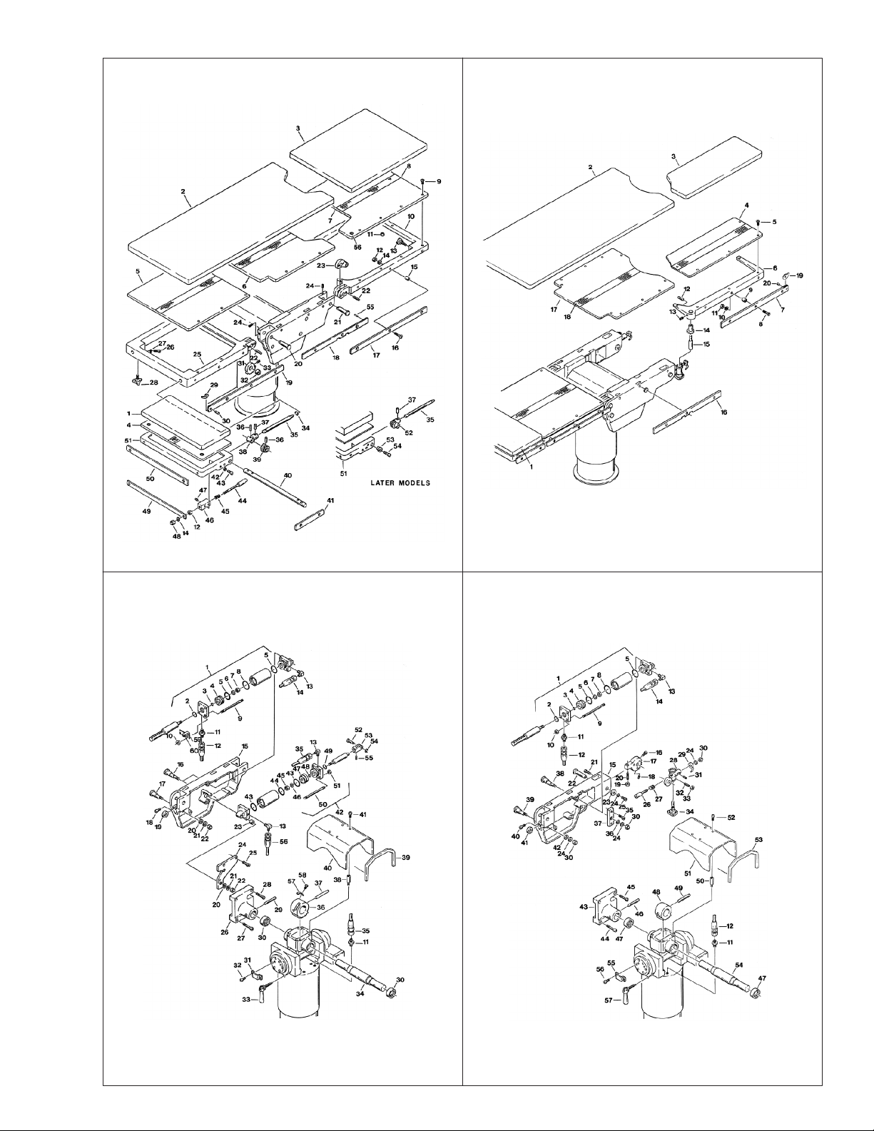
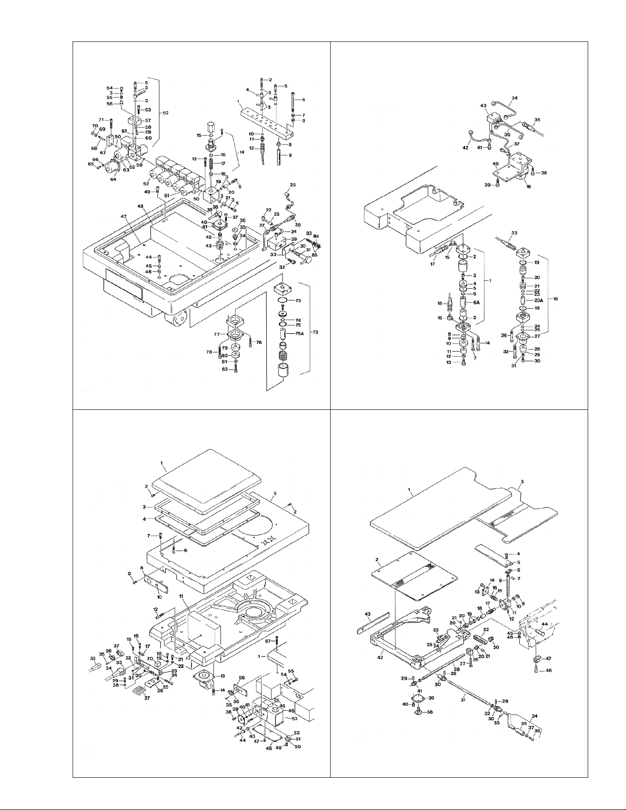
This manual contains the exploded views and replacement parts lists for the serviceable components of the SKYTRON Model 6000/6001 surgical tables.
Each serviceable part in these exploded views is identified by a reference number. Use
this number to locate necessary part information in the parts list adjacent to the exploded
view.
Always use the complete SKYTRON part number and description when ordering
replacement parts.
Always use the complete table serial number (S.N.) when ordering replacement
parts.
Special Tools and Maintenance Items listed on page 50.
Abbreviations
As Required .......................................... A/R
Optional................................................... opt
Serial Number ....................................... S.N.
All Later S.N.'s ......................................... &L
All Prior S.N.'s ..........................................&P
Not Shown............................................... NS
REV 4/00
Although current at the time of publication, SKYTRON's policy of continuous development makes this
manual subject to change without notice.
Page 2
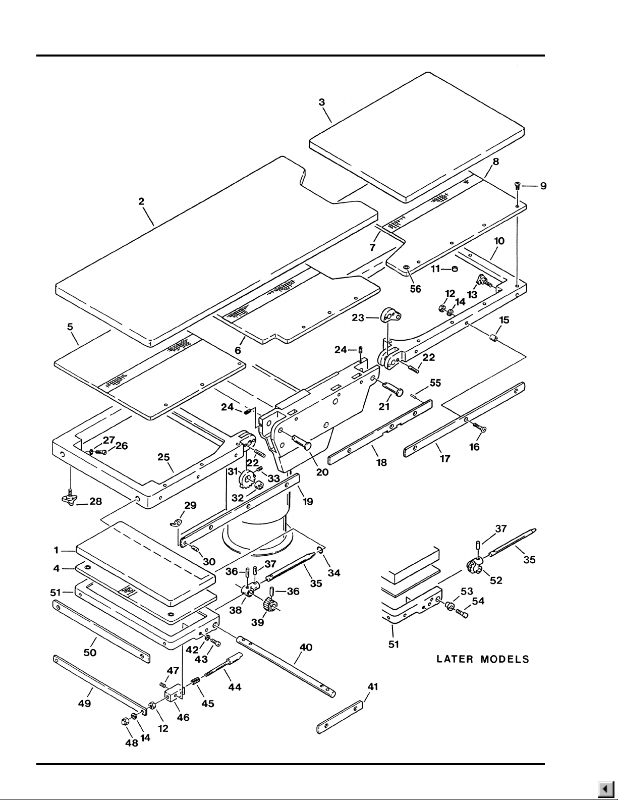
1. TOP & SIDE FRAME ASSEMBLIES, 6001

1. TOP & SIDE FRAME ASSEMBLIES, 6001
Item Part No. Description 6001 6000
1-010-22-P PAD SET .......................................................................................................opt
1-010-15-P PAD SET ......................................................................................................... opt
1 1-010-06-1P PAD, head section.........................................................................................opt opt
2 1-010-06-8P PAD, back/seat section ................................................................................. opt
3 1-010-06-7P PAD, foot/leg section.....................................................................................opt
4 D3-032-04 TOP, head section, S.N. 6001N-1994-10 &L ................................................. 1 1
D3-010-02 TOP, head section.......................................................................................... 1 1
5 D3-010-03 TOP, back section .......................................................................................... 1 1
6 D3-030-02 TOP, seat section ........................................................................................... 1
7 D3-030-03 TOP, foot/leg section ...................................................................................... 1
8 D3-010-18-H VELCRO, hook (specify length) ................................................................... A/R A/R
9 D3-010-19 SCREW, phillips hd., ..................................................................................... 29 29
10 D3-031-64 FRAME, foot/leg section, S.N.6001N-1992-1&L ............................................ 1 1
D3-031-04 FRAME, foot/leg section, S.N.6001-1991-12&P ............................................ 1 1
11 D6-031-23 RUBBER STOP, foot/leg section ................................................................... 1
12 D6-010-13-1 NUT, M8 (plated).......................................................................................... A/R A/R
D6-032-34 NUT, M8 w/ lockwasher ............................................................................... A/R A/R
13 D6-031-01 KNOB, locking ................................................................................................ 2
14 D6-010-09-1 WASHER, lock, M8 ...................................................................................... A/R A/R
15 D3-010-01 COLLAR, side rail......................................................................................... A/R A/R
16 D6-010-12-1 SCREW, allen, M8x45.................................................................................. A/R A/R
17 D3-030-10 RAIL, side, foot/leg section, right.................................................................... 1
D3-030-09 RAIL, side, foot/leg section, left ...................................................................... 1
18 D3-030-08 RAIL, side, seat section, right......................................................................... 1
D3-030-07 RAIL, side, seat section, left ........................................................................... 1
19 D3-031-71 RAIL, side, back section, right, (470mm) S.N. 6001N-1993- -1584&L ........... 1 1
D3-031-72 RAIL, side, back section, left, (470mm) S.N. 6001N-1993- -1584&L ............. 1 1
D3-031-68 RAIL, side, back section, right, (440mm) S.N. 6001-1990-7 to 1993- -1583 .. 1 1
D3-010-33 RAIL, side, back section, right, S.N. 6001-1990-6&P..................................... 1 1
D3-031-69 RAIL, side, back section, left, (440mm) S.N. 6001-1990-7 to 1993- -1583 .... 1 1
D3-010-34 RAIL, side, back section, left, S.N. 6001-1990-6&P ....................................... 1 1
20 D3-010-04 AXIS, back section ......................................................................................... 2 2
21 D3-030-05 AXIS, foot/leg section ..................................................................................... 2
22 D6-010-03 PIN, tapered, spur gear,M7x40 ...................................................................... 8 4
23 D3-031-01 LEVER, axis, foot/leg ..................................................................................... 2
24 D6-010-50 SCREW, set, M6x15 ...................................................................................... 4 2
25 D3-031-23-S FRAME, back section, S.N. 6001N-1992-1&L ............................................... 1 1
D3-031-23 FRAME, back section, S.N. 6001-1991-12&P................................................ 1 1
26 D6-010-67-1 BOLT, allen, M5x15 (plated) .......................................................................... 2 2
27 D6-010-77-1 WASHER, lock, M5 (plated) ........................................................................... 2 2
28 D3-010-17 KNOB, retaining ............................................................................................. 2 2
29 D3-010-43 STOP, rail, large ............................................................................................. 4 4
D3-010-42 STOP, rail, small ............................................................................................ 4 4
30 D3-010-41 PIN, rail stop ................................................................................................... 4 4
31 D3-031-35 GEAR, spur, back section .............................................................................. 2 2
32 D3-010-32 BUSHING, back section ................................................................................. 2 2
33 D6-010-50 SCREW, set, M6x15 ...................................................................................... 2 2
Page 3
Quantity

Page 4
1. TOP & SIDE FRAME ASSEMBLIES, 6001 (CONTINUED)

1. TOP & SIDE FRAME ASSEMBLIES, 6001 (CONTINUED)
Item Part No. Description 6001 6000
34 D4-010-14 O-RING, P-12 ................................................................................................. 2 2
D3-010-45 HEAD SECTION PIVOT ASSY. (includes items 35 through 40) .................. A/R A/R
35 D3-010-31-1 SHAFT, extension, head section, S.N. 6001N-1994-10&L ............................ 2 2
D3-010-31 SHAFT, extension, head section, S.N. 6001N-1994-9&P .............................. 2 2
36 D6-010-15 PIN, tapered, M6x30 (plated) ......................................................................... 4 4
D6-060-05 PIN, roll, M5x25 .............................................................................................. 4 4
37 D6-010-01-1 PIN, tapered, M5x20 (plated) ......................................................................... 2 2
D6-050-33 PIN, roll, M5x20 .............................................................................................. 2 2
38 D3-010-29 TRUNNION, pivot shaft .................................................................................. 2 2
39 D3-010-30 GEAR, ratchet, head section .......................................................................... 2 2
40 D3-010-28 SHAFT, pivot, head section............................................................................ 1 1
41 D3-031-67-1 RAIL, side, head section, S.N. 6001N-1994-10&L ......................................... 2 2
D3-031-67 RAIL, side, head section, S.N. 6001N-1994-9&P........................................... 2 2
42 D6-010-40 WASHER, lock, M6 ........................................................................................ 6 6
43 D6-010-38 BOLT, allen, M6x15........................................................................................ 6 6
44 D3-010-27 PLUNGER, release ........................................................................................ 2 2
45 D3-010-26 SPRING, release ............................................................................................ 2 2
46 D3-031-25-1S BLOCK, bearing, right, silver.......................................................................... 1 1
D3-031-25-1 BLOCK, bearing, right, beige ......................................................................... 1 1
D3-031-25-2S BLOCK, bearing, left, silver ............................................................................ 1 1
D3-031-25-2 BLOCK, bearing, left, beige ............................................................................ 1 1
47 D6-010-11 SCREW, set, M5 x 8 (plated) ......................................................................... 2 2
48 D6-010-08 NUT, acorn ..................................................................................................... 2 2
49 D3-010-24 RELEASE BAR, head section ........................................................................ 1 1
50 D3-010-20 RAIL, accessory ............................................................................................. 1 1
51 D3-032-05 FRAME, head section, S.N. 6001N-1994-10&L ............................................. 1 1
D3-031-27-S FRAME, head section, silver, S.N. 6001-1992-1&L ....................................... 1 1
D3-031-27 FRAME, head section, beige, S.N. 6001-1990-7&L ....................................... 1 1
D3-031-21 FRAME, head section, beige, S.N. 6001-1990-6&P ...................................... 1 1
52 D3-032-80 GEAR/TRUNNION, right, S.N. 6001N-1994-10&L ......................................... 1 1
D3-032-81 GEAR/TRUNNION, left, S.N. 6001N-1994-10&L ........................................... 1 1
53 D3-032-82 AXIS, head section, S.N. 6001N-1994-10&L ................................................. 2 2
54 D6-010-53-1 BOLT, allen, M8x20, S.N. 6001N-1994-10&L ................................................ 2 2
55 D6-032-49 PIN, roll, M3 x 8 .............................................................................................. 2 2
56 5-010-01-8 FLANGE BUSHING, table top ........................................................................ 4 4
Page 5
Quantity
Page 6
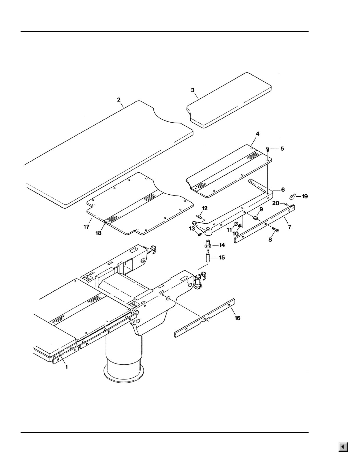
2. TOP & SIDE FRAME ASSEMBLIES, 6000

2. TOP & SIDE FRAME ASSEMBLIES, 6000
Item Part No. Description 6001 6000
1-010-15-P PAD SET ......................................................................................................... opt
1 1-010-08-1P PAD, head section ........................................................................................... opt
2 1-010-08-8P PAD, back/seat section ................................................................................... opt
3 1-010-08-6P PAD, foot/leg section, right .............................................................................. opt
1-010-08-5P PAD, foot/leg section, left ................................................................................ opt
4 D3-020-04 TOP, foot/leg section, right .............................................................................. 1
D3-020-03 TOP, foot/leg section, left ................................................................................ 1
5 D3-010-19 SCREW, top retaining (plated) ........................................................................ 32
6 D3-031-08 FRAME, foot/leg section, right, silver S.N. 6000N-1993-8-86&L..................... 1
D3-031-06-S FRAME, foot/leg section, right, silver S.N. 6000N-1993-8-85&P .................... 1
D3-031-06 FRAME, foot/leg section, right, beige .............................................................. 1
D3-031-07 FRAME, foot/leg section, left, silver S.N. 6000N-1993-8-86&L ....................... 1
D3-031-05-S FRAME, foot/leg section, left, silver S.N. 6000N-1993-8-85&P ...................... 1
D3-031-05 FRAME, foot/leg section, left, beige ................................................................ 1
7 D3-020-10 RAIL, side, foot/leg section, right..................................................................... 1
D3-020-09 RAIL, side, foot/leg section, left ....................................................................... 1
8 D6-010-12-1 SCREW, phillips, M8x35 (plated) .................................................................... 1
9 D3-010-01 COLLAR, side rail............................................................................................ 20
10 D6-010-09-1 WASHER, lock, M8 (plated) ............................................................................ 20
11 D6-010-13-1 NUT, M8 (plated)............................................................................................. 20
D6-032-34 NUT, M8 w/ lockwasher .................................................................................. A/R
12 D6-020-01 PIN, tapered, 6x50 .......................................................................................... 2
13 D6-010-50 SCREW, set, M6x15 ....................................................................................... 2
14 D3-020-19 CLUTCH, foot/leg ............................................................................................ 2
15 D3-031-14 AXIS, foot/leg S.N. 6000N-1993-8-86&L ......................................................... 2
D3-020-20 AXIS, foot/leg S.N. 6000N-1993-8-85&P ........................................................ 2
16 D3-020-08 RAIL, side, seat section, right.......................................................................... 1
D3-020-07 RAIL, side, seat section, left ............................................................................ 1
17 D3-020-02 TOP, seat section ............................................................................................ 1
18 D3-010-18 VELCRO (specify length) ................................................................................ A/R
19 D3-010-42 STOP, rail, small ............................................................................................. 2
D3-010-43 STOP, rail, large .............................................................................................. 2
20 D3-010-41 PIN, rail stop .................................................................................................... 2
Page 7
Quantity

Page 8
3. SIDE FRAME & HYDRAULIC CYLINDERS, 6001

3. SIDE FRAME & HYDRAULIC CYLINDERS, 6001
Item Part No. Description 6001 6000
1 D4-032-01 CYLINDER ASSEMBLY, back section, S.N. 6001-1986-11&L ...................... 2
D4-031-36 CYLINDER ASSEMBLY, back section, S.N. 6001-1986-10&P ...................... 2
2 D4-010-03 •O-RING, P-25................................................................................................ 1
3 D4-010-02 •O-RING, P-14, S.N. 6001-1986-11&L ........................................................... 1
D4-060-04 •O-RING, P-15, S.N. 6001-1986-10&P .......................................................... 1
4 D4-010-47 •PISTON, cylinder .......................................................................................... 1
5 D4-010-04 •O-RING, P-44................................................................................................ 2
6 D6-010-42 •WASHER, lock, M10 ..................................................................................... 1
7 D6-010-43 •NUT, M10 ...................................................................................................... 1
8 D4-010-09 •O-RING, G-50 (fits in tube ID) ....................................................................... 1
D4-010-04 •O-RING, P-44 (fits on end cap OD) .............................................................. 1
9 D4-010-48 •STUD, cylinder .............................................................................................. 4
10 D6-010-55 •NUT, M8........................................................................................................ 4
11 D4-031-06 FITTING, flexible hose ................................................................................. A/R
D4-031-69 FITTING, special, flexible hose .................................................................... A/R
D4-031-70 NUT .............................................................................................................. A/R
12 D4-031-01 HOSE, flexible, back section ram, left ............................................................ 1
D4-031-02 HOSE, flexible, back section ram, right .......................................................... 1
13 D4-010-29 FITTING, hydraulic, 90° elbow ..................................................................... A/R
14 D4-031-03 HOSE, flexible, back section piston, left......................................................... 1
D4-031-04 HOSE, flexible, back section piston, right ...................................................... 1
15 D3-031-11 FRAME, side, left, beige................................................................................. 1
D3-031-11-S FRAME, side, left, silver ................................................................................. 1
D3-031-73 FRAME, side, left, silver, -KR models ............................................................ 1
D3-031-12 FRAME, side, right, beige .............................................................................. 1
D3-031-12-S FRAME, side, right, silver............................................................................... 1
D3-031-74 FRAME, side, right, silver, -KR models .......................................................... 1
16 D3-010-37 AXIS, eccentric cam, cylinder......................................................................... 4
17 D3-010-38 AXIS, eccentric cam, bearing ......................................................................... 2
18 D6-010-73-1 BOLT, allen, M6x12 (plated) .......................................................................... 2
19 D3-010-36 BEARING, support ......................................................................................... 2
20 D6-010-72 WASHER, flat, M8 (plated)............................................................................. 6
21 D6-010-09-1 WASHER, lock, M8 (plated) ........................................................................... 6
22 D6-010-08 NUT, acorn, M8 (plated) ................................................................................. 6
23 D6-030-04 SPACER......................................................................................................... 4
24 D3-031-20 BRACE, side frame, left, beige....................................................................... 1
D3-031-20-S BRACE, side frame, left, silver ....................................................................... 1
D3-031-19 BRACE, side frame, right, beige .................................................................... 1
D3-031-19-S BRACE, side frame, right, silver..................................................................... 1
25 D6-010-17-1 BOLT, allen, M8x15 (plated) .......................................................................... 8
26 D3-031-17-S INNER CASTING, side frame, left, S.N.6001N-1992-1&L ............................. 1
D3-031-17-1 INNER CASTING, side frame, left, S.N.6001-1986-1 to S.N.6001-1991-12 .. 1
D3-031-17 INNER CASTING, side frame, left, S.N.6001-1985-12&P ............................. 1
D3-031-75 INNER CASTING, side frame, left, -KR models ............................................. 1
D3-031-18-S INNER CASTING, side frame, right, S.N.6001N-1992-1&L ........................... 1
D3-031-18-1 INNER CASTING, side frame, right, S.N.6001-1986-1 to S.N.6001-1991-12 1
D3-031-18 INNER CASTING, side frame, right, S.N.6001-1985-12&P ........................... 1
D3-031-76 INNER CASTING, side frame, right, -KR models........................................... 1
Page 9
Quantity

Page 10
3. SIDE FRAME & HYDRAULIC CYLINDERS, 6001 (CONTINUED)

3. SIDE FRAME & HYDRAULIC CYLINDERS, 6001 (CONTINUED)
Item Part No. Description 6001 6000
27 D6-010-10-2 BOLT, allen, M10x45 (plated) ........................................................................ 4
28 D6-010-71-1 BOLT, allen, M10x40 (plated) ........................................................................ 4
29 D6-010-06 PIN, tapered,12x70 ........................................................................................ 2
D6-032-01 PIN, tapered, -KR models .............................................................................. 2
30 D2-010-41 BEARING, trendelenburg axis........................................................................ 2
D2-032-01 BEARING, trendelenburg axis, -KR models ................................................... 2
31 D2-030-01 BRACKET, pendant control............................................................................ 1
32 D6-031-02 SCREW, phillips hd. ....................................................................................... 2
33 D2-010-42 HANDLE, table top locking ............................................................................. 1
34 D2-010-40 AXIS, trendelenburg ....................................................................................... 1
D2-032-03 AXIS, trendelenburg, -KR models .................................................................. 1
35 D4-031-05 HOSE, flexible, foot/leg section ram, left ........................................................ 1
D4-031-04 HOSE, flexible, foot/leg section ram, right...................................................... 1
36 D2-032-32 GEAR, trendelenburg, S.N. 6001-1991-7&L .................................................. 1
D2-010-39 GEAR, trendelenburg, S.N. 6001-1991-6&P .................................................. 1
37 D6-010-07 PIN, tapered, M12x90 .................................................................................... 1
38 D2-010-38 STAND-OFF, cover ........................................................................................ 4
39 D2-031-13 END CAP, cover, right.................................................................................... 1
40 D2-031-37 COVER, flexible hose..................................................................................... 1
41 D6-010-70-1 BOLT, allen, M5x10 (plated) .......................................................................... 4
42 D4-032-02 CYLINDER ASSEMBLY, leg section, S.N. 6001-1986-10&L ......................... 2
D4-031-16 CYLINDER ASSEMBLY, leg section, S.N. 6001-1986-9&P .......................... 2
43 D4-010-54 •O-RING, P-34................................................................................................ 2
44 D4-010-54 •O-RING, P-34, S.N. 6001-1986-10&L ........................................................... 1
D4-010-55 •O-RING, G-40, S.N. 6001-1986-9&P ............................................................ 1
45 D6-010-43 •NUT, M10 ...................................................................................................... 1
46 D4-010-42 •WASHER, lock, M10 ..................................................................................... 1
47 D4-031-15 •PISTON, cylinder .......................................................................................... 1
48 D4-010-02 •O-RING, P-14................................................................................................ 1
D4-060-04 •O-RING, P-15................................................................................................ 1
49 D4-010-03 •O-RING, P-25................................................................................................ 1
50 D4-010-48 •STUD, cylinder .............................................................................................. 4
51 D6-010-55 •NUT, M8........................................................................................................ 4
52 D6-030-03 PIN, clevis ...................................................................................................... 2
53 D6-031-19 CLEVIS........................................................................................................... 2
54 D6-030-01 CIRCLIP ......................................................................................................... 2
55 D6-010-34 SCREW, set, M6x6 ........................................................................................ 8
56 D4-031-07 HOSE, flexible, foot/leg section piston, left .................................................... 1
D4-031-05 HOSE, flexible, foot/leg section piston, right .................................................. 1
57 D2-032-48 RAMP, micro-switch, -KR models .................................................................. 2
58 D6-050-36 BOLT, allen, M5x8, -KR models ..................................................................... 4
59 D3-032-42 BRACKET, micro-switch, -KR models............................................................ 2
60 D5-032-15 MICRO-SWITCH, -KR models ....................................................................... 2
NS D5-032-49 RISER CORD, -KR models ............................................................................ 1
Page 11
Quantity

Page 12
4. SIDE FRAME & HYDRAULIC CYLINDERS, 6000

4. SIDE FRAME & HYDRAULIC CYLINDERS, 6000
Item Part No. Description 6001 6000
1 D4-032-01 CYLINDER ASSEMBLY, back section, S.N. 6000-1986-11&L ....................... 2
D4-031-36 CYLINDER ASSEMBLY, back section, S.N. 6000-1986-10&P ....................... 2
2 D4-010-03 •O-RING, P-25................................................................................................. 1
3 D4-010-02 •O-RING, P-14, S.N. 6001-1986-11&L ............................................................ 1
D4-060-04 •O-RING, P-15, S.N. 6001-1986-10&P ........................................................... 1
4 D4-010-47 •PISTON, cylinder ........................................................................................... 1
5 D4-010-04 •O-RING, P-44................................................................................................. 2
6 D6-010-42 •WASHER, lock, M10 ...................................................................................... 1
7 D6-010-43 •NUT, M10 ....................................................................................................... 1
8 D4-010-09 •O-RING, G-50 (fits in tube ID) ........................................................................ 1
D4-010-04 •O-RING, P-44 (fits on end cap OD) ............................................................... 1
9 D4-010-48 •STUD, cylinder ............................................................................................... 4
10 D6-010-55 •NUT, M8......................................................................................................... 4
11 D4-031-06 FITTING, flexible hose .................................................................................... A/R
D4-031-69 FITTING, special, flexible hose ....................................................................... A/R
D4-031-70 NUT ................................................................................................................. A/R
12 D4-031-01 HOSE, flexible, back section ram, left ............................................................. 1
D4-031-02 HOSE, flexible, back section ram, right ........................................................... 1
13 D4-010-29 FITTING, hydraulic, 90° elbow ........................................................................ A/R
14 D4-031-03 HOSE, flexible, back section piston, left.......................................................... 1
D4-031-04 HOSE, flexible, back section piston, right ....................................................... 1
15 D3-031-30 FRAME, side, left, beige.................................................................................. 1
D3-031-30-S FRAME, side, left, silver .................................................................................. 1
D3-031-31 FRAME, side, right, beige ............................................................................... 1
D3-031-31-S FRAME, side, right, silver................................................................................ 1
16 D6-010-51-1 BOLT, allen, M6x10 (plated) ........................................................................... 2
17 D3-021-21 GEAR, ratchet, left .......................................................................................... 1
D3-021-21-1 GEAR, ratchet, right ........................................................................................ 1
18 D6-020-11 SCREW, set, M6 ............................................................................................. 2
19 D6-010-56-1 NUT, M10, 1.5 pitch (plated) ........................................................................... 2
20 D6-020-05 BOLT, adjustment, M10x40 (plated) ............................................................... 2
21 D6-010-30-1 BOLT, allen, M6x20 (plated) ........................................................................... 6
22 D3-020-32 AXIS, pivot, leg section ................................................................................... 2
23 D6-020-03 WASHER, ratchet (plated) .............................................................................. 2
24 D6-010-09-1 WASHER, lock, M8 (plated) ............................................................................ 6
25 D6-010-52-1 BOLT, allen, M8x20 (plated) ........................................................................... 2
26 D3-020-28 PAWL, ratchet ................................................................................................. 2
27 D3-020-27 SPRING, ratchet.............................................................................................. 2
28 D3-031-09 SUPPORT BRACKET, leg section, left S.N. 6000N-1993-8-86&L ................. 1
D3-020-22 SUPPORT BRACKET, leg section, left S.N. 6000N-1993-8-85&P ................. 1
D3-031-10 SUPPORT BRACKET, leg section, right S.N. 6000N-1993-8-86&L ............... 1
D3-020-23 SUPPORT BRACKET, leg section, right S.N. 6000N-1993-8-85&P ............... 1
29 D3-020-24 HANDLE, ratchet ............................................................................................. 2
30 D6-010-08 NUT, acorn, M8 (plated) .................................................................................. 6
31 D6-010-11 SCREW, set, M5x8 (plated) ............................................................................ 2
32 D6-020-02 SCREW, set, tipped (plated) ........................................................................... 2
33 D6-010-13-1 NUT, M8 (plated)............................................................................................. 2
34 D3-031-26 HANDLE, clutch .............................................................................................. 2
Page 13
Quantity

Page 14
4. SIDE FRAME & HYDRAULIC CYLINDERS, 6000 (CONTINUED)

4. SIDE FRAME & HYDRAULIC CYLINDERS, 6000 (CONTINUED)
Item Part No. Description 6001 6000
35 D6-010-54-1 BOLT, allen, M8x30 (plated) ........................................................................... 4
36 D6-020-04 WASHER, special (plated) .............................................................................. 2
37 D3-031-29 BRACE, side frame, left, beige........................................................................ 2
D3-031-29-S BRACE, side frame, left, silver ........................................................................ 2
38 D3-010-37 AXIS, eccentric cam, cylinder.......................................................................... 4
39 D3-010-38 AXIS, eccentric cam, bearing .......................................................................... 2
40 D6-010-73-1 BOLT, allen, M6x12 (plated) ........................................................................... 2
41 D3-010-36 BEARING, support .......................................................................................... 2
42 D6-010-72 WASHER, flat, M8 (plated).............................................................................. 6
43 D3-031-33-S INNER CASTING, side frame, left, S.N. 6000N-1992-1&L ............................. 1
D3-031-33-1 INNER CASTING, side frame, left, S.N. 6000-1986-1 to S.N. 6001-1991-12 . 1
D3-031-33 INNER CASTING, side frame, left, S.N. 6000-1985-12&P ............................. 1
D3-031-34-S INNER CASTING, side frame, right, S.N. 6000N-1992-1&L ........................... 1
D3-031-34-1 INNER CASTING, side frame, right, S.N. 6000-1986-1 to S.N. 6001-1991-12 1
D3-031-34 INNER CASTING, side frame, right, S.N. 6000-1985-12&P ........................... 1
44 D6-010-10-2 BOLT, allen,M10x45 (plated) .......................................................................... 4
45 D6-010-71-1 BOLT, allen, M10x40 (plated) ......................................................................... 4
46 D6-010-06 PIN, tapered,12x70 ......................................................................................... 2
47 D2-010-41 BEARING, trendelenburg axis......................................................................... 2
48 D2-032-32 GEAR, trendelenburg, S.N. 6000-1991-7&L ................................................... 1
D2-010-39 GEAR, trendelenburg, S.N. 6000-1991-6&P ................................................... 1
49 D6-010-07 PIN, tapered, M12x90 ..................................................................................... 1
50 D2-010-38 STAND-OFF, cover ......................................................................................... 4
51 D2-031-37 COVER, flexible hose...................................................................................... 1
52 D6-010-70-1 BOLT, allen, M5x10 (plated) ........................................................................... 4
53 D2-031-13 END CAP, cover, right..................................................................................... 1
54 D2-010-40 AXIS, trendelenburg ........................................................................................ 1
55 D2-030-01 BRACKET, pendant control............................................................................. 1
56 D6-031-02 SCREW, phillips hd. ........................................................................................ 2
57 D2-010-42 HANDLE, table top locking .............................................................................. 1
Page 15
Quantity

Page 16
5. TRENDELENBURG & LATERAL TILT CYLINDERS

5. TRENDELENBURG & LATERAL TILT CYLINDERS
Item Part No. Description 6001 6000
1 D6-010-29 BOLT, allen, M10x85...................................................................................... 4 4
2 D2-032-16 CASTING, trend. bearing, S.N. 6000N-1992-1&L .......................................... 1 1
D2-031-22 CASTING, trend. bearing, S.N. 6000-1991-12&P .......................................... 1 1
3 D2-032-31 PISTON, trendelenburg, S.N. 6000-1991-7&L ............................................... 2 2
D2-032-41 PISTON, trendelenburg, S.N. 6000-1991-6&P............................................... 2 2
4 D4-010-06 O-RING, P-60 ................................................................................................. 2 2
5 D4-010-07 O-RING, IBP-95 ............................................................................................. 4 4
6 D2-032-15 PIVOT BLOCK, lateral tilt, tail, S.N. 6000N-1992-1&L ................................... 1 1
D2-031-03-1 PIVOT BLOCK, lateral tilt, tail, S.N. 6000-1986-8 to S.N. 6000-1991-12 ....... 1 1
D2-031-03 PIVOT BLOCK, lateral tilt, tail, S.N. 6000-1986-7&P ..................................... 1 1
7 D2-032-14 BUSHING, graphite, S.N. 6000N-1992-1&L................................................... 2 2
D2-031-05 BUSHING, graphite, S.N. 6000-1986-8 to S.N. 6000-1991-12 ...................... 2 2
D2-031-06 BUSHING, graphite, S.N. 6000-1986-7&P ..................................................... 2 2
8 D4-010-06 O-RING, P-60, S.N. 6000-1987-6&L .............................................................. 2 2
D4-010-10 O-RING, G-65, S.N. 6000-1987-5&P ............................................................. 2 2
9 D4-032-80 O-RING, S-70, S.N. 6001-1992-9-1454&L ..................................................... 2 2
10 D2-032-13-1 CAP, tail, S.N. 6000N-1992-1&L .................................................................... 1 1
D2-031-26 CAP, tail, S.N. 6000-1986-1 to S.N. 6000-1991-12 ........................................ 1 1
D2-010-26 CAP, tail, S.N. 6000-1985-12&P .................................................................... 1 1
11 D6-010-30 BOLT, allen, M6x20........................................................................................ 6 6
12 D4-010-32 PACKING, copper ........................................................................................ A/R A/R
13 D4-010-99 FITTING, plumbing ....................................................................................... A/R A/R
14 D4-010-29 FITTING, hydraulic, 90° elbow ..................................................................... A/R A/R
15 D6-031-28 PIN, tapered, 12x55, S.N. 6000N-1992-1&L .................................................. 1 1
D6-011-05 PIN, tapered, 12x60, S.N. 6000-1986-1 to S.N. 6000-1991-12 ...................... 1 1
D6-010-06 PIN, tapered, 12x70, S.N. 6000-1985-12&P .................................................. 1 1
16 D2-032-12-1 LEVER, lateral tilt motion, S.N. 6000N-1992-1&L .......................................... 1 1
D2-031-27 LEVER, lateral tilt motion, S.N. 6000-1986-1 to S.N. 6000-1991-12 .............. 1 1
D2-010-27 LEVER, lateral tilt motion, S.N. 6000-1985-12&P .......................................... 1 1
17 D4-010-01 O-RING, P-8 ................................................................................................... 2 2
18 D2-032-10 PLATE, inspection cover, S.N. 6000N-1992-1&L........................................... 1 1
D2-010-29 PLATE, inspection cover, S.N. 6000-1991-12&P ........................................... 1 1
D2-032-47 PLATE, inspection cover, battery model ........................................................ 1
19 D6-010-16-1 SCREW, phillips hd., M5x6 (stainless)........................................................... 2 2
20 D2-032-06-1 HOUSING, lateral tilt, S.N. 6000N-1992-1&L................................................. 1 1
D2-031-30-1 HOUSING, lateral tilt, S.N. 6000-1986-1 to S.N. 6000-1991-12 .................... 1 1
D2-031-30 HOUSING, lateral tilt, S.N. 6000-1985-12&P ................................................. 1 1
21 D6-010-45 BOLT, allen, M10x30...................................................................................... 3 3
D6-010-31 BOLT, allen, M10x25 ...................................................................................... 3 3
22 D2-032-07-1 ROD, piston, S.N. 6000N-1992-1&L .............................................................. 2 2
D2-031-31 ROD, piston, S.N. 6000-1986-1 to S.N. 6000-1991-12 .................................. 2 2
D2-010-31 ROD, piston, S.N. 6000-1985-12&P ............................................................... 2 2
23 D2-032-08-1 PISTON, lateral tilt, S.N. 6000N-1992-1&L .................................................... 2 2
D2-031-32 PISTON, lateral tilt, S.N. 6000-1986-1 to S.N. 6000-1991-12 ........................ 2 2
D2-010-32 PISTON, lateral tilt, S.N. 6000-1985-12&P .................................................... 2 2
24 D4-060-24 O-RING, P-49, S.N. 6000N-1992-1&L ........................................................... 2 2
D4-010-04 O-RING, P-44, S.N. 6000-1986-1 to S.N. 6000-1991-12 ............................... 2 2
D4-010-05 O-RING, P-50A, S.N. 6000-1985-12&P ......................................................... 2 2
Page 17
Quantity

Page 18
5. TRENDELENBURG & LATERAL TILT CYLINDERS (CONTINUED)

5. TRENDELENBURG & LATERAL TILT CYLINDERS (CONTINUED)
Item Part No. Description 6001 6000
25 D4-060-24 O-RING, P-49, S.N. 6000N-1992-1&L ........................................................... 2 2
D4-031-31 O-RING, G-45, S.N. 6000-1986-1 to S.N. 6000-1991-12............................... 2 2
D4-010-13 O-RING, G-55, S.N. 6000-1985-12&P ........................................................... 2 2
26 D4-032-79 O-RING, S-55, S.N. 6001-1992-9-1454&L ..................................................... 2 2
27 D2-032-09-1 CAP, lateral tilt, S.N. 6000N-1992-1&L .......................................................... 2 2
D2-031-33 CAP, lateral tilt, S.N. 6000-1986-1 to S.N. 6000-1991-12 .............................. 2 2
D2-010-33 CAP, lateral tilt, S.N. 6000-1985-12&P .......................................................... 2 2
28 D6-010-33-1 BOLT, allen, M8x25 (plated) .......................................................................... 8 8
29 D4-031-06 FITTING, flexible hose ................................................................................. A/R A/R
30 D6-010-21 WASHER, lock, M12 ...................................................................................... 2 2
31 D6-010-10-6 BOLT, allen, M12x45...................................................................................... 2 2
32 D6-010-10-7 NUT, M12 ....................................................................................................... 2 2
33 D2-010-43 BAR, hose guide ............................................................................................ 2 2
34 D2-010-45 HOLDER, hose............................................................................................... 2 2
35 D6-010-10-8 BOLT, allen, M5x18........................................................................................ 2 2
36 D4-010-33 FITTING, flexible hose, long......................................................................... A/R A/R
37 D2-031-09 PIVOT BLOCK, lateral tilt, head, S.N. 6000N-1992-1&L................................ 1 1
D2-031-04-1 PIVOT BLOCK, lateral tilt, head, S.N. 6000-1986-8 to S.N. 6000-1991-12 ... 1 1
D2-031-04 PIVOT BLOCK, lateral tilt, head, S.N. 6000-1986-7&P .................................. 1 1
D2-032-18 PIVOT BLOCK, lateral tilt, head, -KR models ................................................ 1
38 D2-032-33 HOUSING, trendelenburg, S.N. 6000N-1992-1&L ......................................... 1 1
D2-031-36 HOUSING, trendelenburg, S.N. 6000-1991-12&P ......................................... 1 1
39 D6-010-30-1 BOLT, allen, M6x20 (plated) .......................................................................... 6 6
40 D2-031-34 CAP, head, trend. cyl., S.N. 6000N-1992-1&L ............................................... 1 1
D2-030-05 CAP, head, trend. cyl., S.N. 6000-1991-12&P ............................................... 1 1
D2-032-19 CAP, head, trend. cyl., -KR models ................................................................ 1
41 D6-010-70-1 BOLT, allen, M5x10 (plated), -KR models...................................................... 3
42 D2-032-20 COVER, trendelenburg cylinder, -KR models ................................................ 1
43 D2-032-46 BRACKET, micro-switch, -KR models............................................................ 2
44 D5-032-16 MICRO-SWITCH, -KR models ....................................................................... 2
D5-032-66 ACTUATOR, micro switch ............................................................................ A/R
45 D2-032-45 BRACKET, micro-switch, -KR models............................................................ 2
46 D5-032-15 MICRO-SWITCH, -KR models ....................................................................... 2
NS D5-032-49 RISER CORD, -KR models ............................................................................ 1
Page 19
Quantity
Page 20
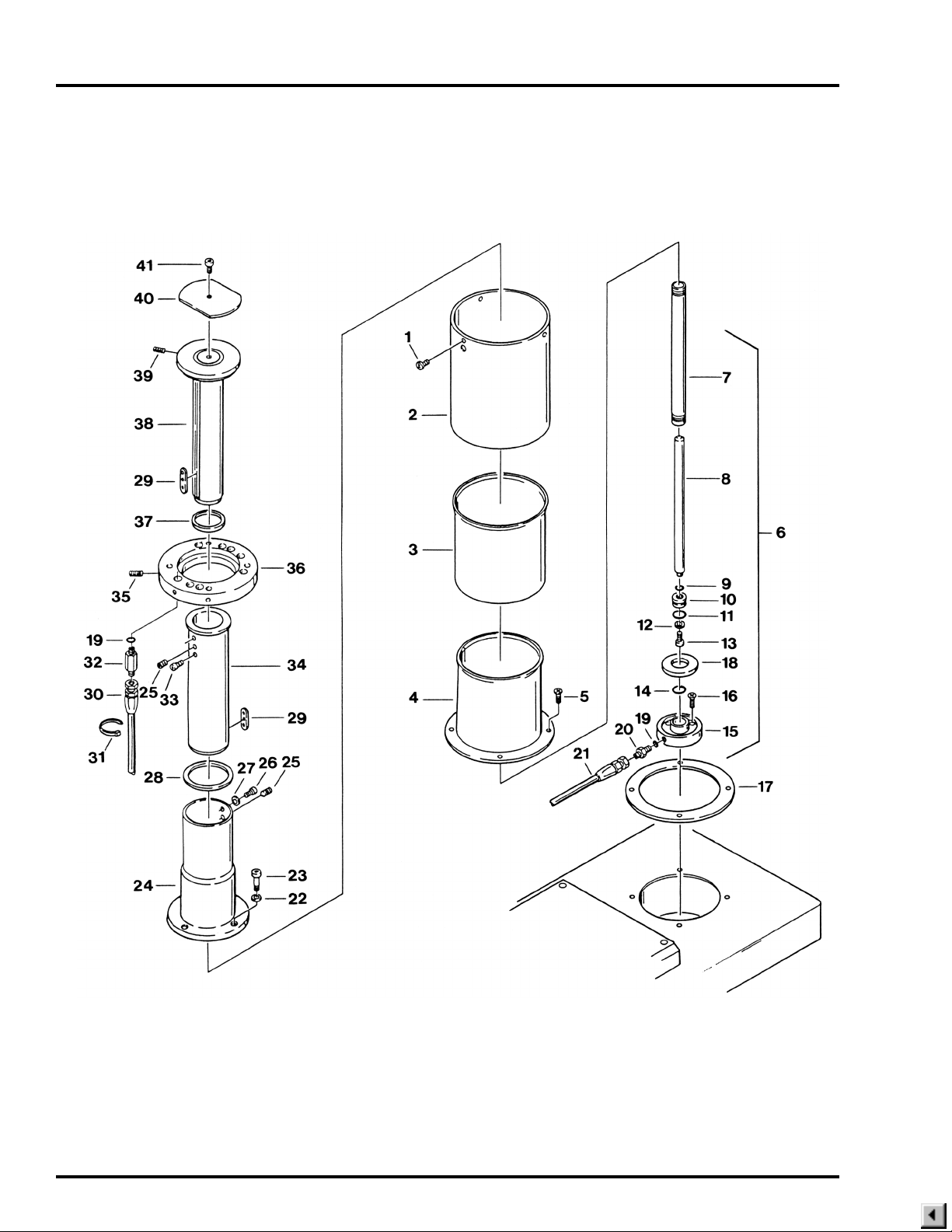
6. SUPPORT COLUMN ASSEMBLY

6. SUPPORT COLUMN ASSEMBLY
Item Part No. Description 6001 6000
1 D6-010-16-1 SCREW, phillips, M5x6 (stainless) ................................................................. 3 3
2 D2-010-03-1 SHROUD, elevation, exterior ......................................................................... 1 1
3 D2-010-04-1 SHROUD, elevation, middle ........................................................................... 1 1
4 D2-031-07 SHROUD, elevation, inner, S.N. 6000N-1992-1&L ........................................ 1 1
D2-010-05-1 SHROUD, elevation, inner, S.N. 6000-1991-12&P ........................................ 1 1
5 D6-010-19-1 SCREW, phillips, M5x10 (plated) ................................................................... 4 4
6 D4-031-57 ELEVATION CYLINDER ASSEMBLY............................................................ 1 1
7 D2-010-06 •TUBE, elevation cylinder............................................................................... 1 1
8 D2-010-07 •ROD, elevation cylinder ................................................................................ 1 1
9 D4-010-14 •O-RING, P-12................................................................................................ 1 1
10 D2-010-08 •PISTON, elevation cylinder (30mm).............................................................. 1 1
11 D4-010-12 •O-RING, P-24 (30mm piston)........................................................................ 1 1
12 D2-010-09 •WASHER, elevation piston ........................................................................... 1 1
13 D6-010-38 •BOLT, allen, M6x15 ...................................................................................... 1 1
14 D4-010-15 •O-RING, AN6227-24 (30mm piston) ............................................................. 1 1
15 D2-010-11-1 •SAUCER, elevation cylinder ......................................................................... 1 1
16 D6-010-18 BOLT, cylinder saucer mtg.,M8x25 ................................................................ 2 2
17 D2-010-12-1 GASKET, shroud............................................................................................ 1 1
18 D2-010-10 CUSHION, rubber dropping ........................................................................... 1 1
19 D4-010-32 PACKING, copper ........................................................................................ A/R A/R
20 D4-010-31 FITTING, flexible hose, short ......................................................................... 1 1
21 D4-010-23 HOSE, flexible, elevation cylinder (240mm) ................................................... 1 1
22 D6-010-21 WASHER, lock, M12 ...................................................................................... 3 3
23 D6-010-22 BOLT, allen, M12x35...................................................................................... 3 3
24 D2-031-08 HOLDER, slider, S.N. 6000N-1992-1&L ........................................................ 1 1
D2-010-13-1 HOLDER, slider, S.N. 6000-1991-12&P ......................................................... 1 1
25 D2-010-14 BOSS, slider ................................................................................................... 2 2
26 D6-010-17 BOLT, allen, M8x15........................................................................................ 2 2
27 D6-010-09 WASHER, lock, M8 ........................................................................................ 2 2
28 D2-010-15 STOPPER, slider, large.................................................................................. 1 1
29 D2-010-16 KEY, slider...................................................................................................... 2 2
30 D4-010-21-1 HOSE, flexible, 1010mm .............................................................................. A/R A/R
D4-010-21-3 HOSE, flexible, 980mm ................................................................................ A/R A/R
D4-010-21 HOSE, flexible, 1030mm .............................................................................. A/R A/R
D4-010-21-6 HOSE, flexible, 1110mm .............................................................................. A/R A/R
31 D6-010-24 TIE, cable ..................................................................................................... A/R A/R
32 D4-010-33 FITTING, flexible hose, long........................................................................... 3 3
33 D6-010-25 BOLT, allen, M8x6.......................................................................................... 2 2
34 D2-010-17 SLIDER, large ................................................................................................ 1 1
35 D6-010-26 STOPPER, rotation, M10x20 ......................................................................... 2 2
36 D2-031-10 RING, elevation clamp, S.N. 6001N-1992-1&L .............................................. 1 1
D2-031-02 RING, elevation clamp, S.N. 6000-1991-12&P .............................................. 1
D2-031-01 RING, elevation clamp, S.N. 6000-1991-12&P ............................................... 1
D2-031-11 RING, elevation clamp ................................................................................... 1 1
D2-032-40 BALL, steel, 4mm ......................................................................................... A/R A/R
37 D2-010-19 STOPPER, slider, small ................................................................................. 1 1
38 D2-031-20 SLIDER, small ................................................................................................ 1 1
39 D6-010-27 SCREW, set, M10x15 .................................................................................... 2 2
40 D2-010-21 PLATE, elevation slider head ......................................................................... 1 1
41 D6-010-28 BOLT, allen, M5x6.......................................................................................... 1 1
Page 21
Quantity
Page 22
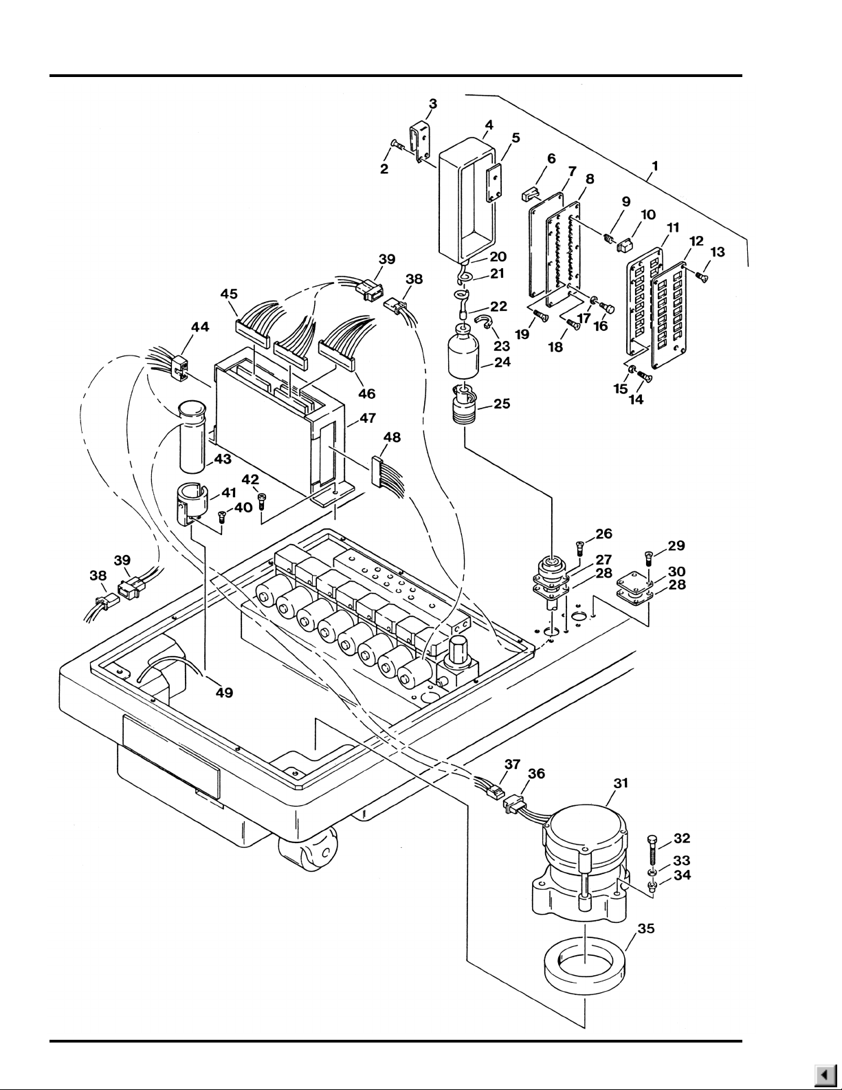
7. ELECTRICAL COMPONENTS

7. ELECTRICAL COMPONENTS
Item Part No. Description 6001 6000
1 D5-031-63 PENDANT CONTROL ASSY. (letters) S.N. 6001-1992-3&L ......................... 1
D5-031-61 PENDANT CONTROL ASSY. (letters) S.N. 6000-1992-3&L .......................... 1
D5-031-29 PENDANT CONTROL ASSY. (one touch) S.N. 6001-1992-2&P................... 1
D5-031-30 PENDANT CONTROL ASSY. (one touch) S.N. 6000-1992-2&P.................... 1
D5-031-11 PENDANT CONTROL ASSY. (two touch) ..................................................... 1
D5-031-12 PENDANT CONTROL ASSY. (two touch) ...................................................... 1
D5-031-69 PENDANT CONTROL ASSY. (6001KR) ........................................................ 1
2 D6-032-33 •SCREW, pendant hook, M4x12 .................................................................... 3 3
3 D5-031-14 •HOOK, pendant............................................................................................. 1 1
4 D5-031-22 •COVER, rubber ............................................................................................. 1 1
5 D5-031-34 •INSERT, pendant hook ................................................................................. 1 1
6 D5-030-23 •MICRO-SWITCH......................................................................................... A/R A/R
7 D5-031-21 •GASKET, micro-switch plate......................................................................... 1 1
8 D5-031-20 •PLATE, micro-switch mounting ..................................................................... 1 1
9 D5-031-07 •SPRING, pendant button ............................................................................ A/R A/R
10 •BUTTON, pendant (specify function & S.N.)............................................... A/R A/R
11 D5-031-12-1 •HOLDER, plastic button ................................................................................ 1 1
12 D5-031-64 •FACE PLATE, pendant control, S.N. 6001-1992-3&L................................... 1
D5-031-62 •FACE PLATE, pendant control, S.N. 6001-1992-3&L.................................... 1
D5-031-33 •FACE PLATE, pendant control, S.N. 6001-1992-2&P (one touch) ............... 1
D5-031-32 •FACE PLATE, pendant control, S.N. 6000-1992-2&P (one touch) ................ 1
D5-031-26 •FACE PLATE, pendant control, two touch .................................................... 1
D5-031-25 •FACE PLATE, pendant control, two touch ..................................................... 1
D5-031-70 •FACE PLATE, pendant control, (6001KR) .................................................... 1
13 D6-010-80-1 •SCREW, phillips hd., M3x6 ........................................................................... 4 4
14 D6-010-10-9 •SCREW, phillips hd., M3x15 ......................................................................... 6 6
15 D5-030-42 •WASHER, special ......................................................................................... 6 6
16 D5-030-43 •INDICATOR LIGHT, green............................................................................ 1 1
17 D5-030-48 •CHROME RING, indicator light ..................................................................... 1 1
18 D6-032-15 •SCREW, M3x10 ............................................................................................ 2 2
19 D6-010-109 •SCREW, M3x16 ............................................................................................ 6 6
20 D5-031-13-1 •STRAIN RELIEF, pendant end ..................................................................... 1 1
21 D5-031-13 •CORD, pendant control ................................................................................. 1 1
22 D5-031-13-2 •STRAIN RELIEF, connector end................................................................... 1 1
23 D6-010-24 •TIE, cable ...................................................................................................... 1 1
24 D5-030-18 •COVER, cannon connector ........................................................................... 1 1
25 D5-030-21 •CONNECTOR, cannon (male 19 pin) ........................................................... 1 1
26 D6-010-57-1 SCREW, phillips hd., M4x10 (plated) ............................................................. 4 4
27 D5-030-20 CONNECTOR, cannon (female 19 pin) ......................................................... 1 1
28 D5-030-46 GASKET, connector ....................................................................................... 2 2
29 D6-032-10 SCREW .......................................................................................................... 4 4
30 D5-032-20 COVER, auxiliary base connector .................................................................. 1 1
31 D4-030-05 PUMP/MOTOR ASSEMBLY .......................................................................... 1 1
32 D6-011-19 BOLT, allen, M5x75........................................................................................ 3 3
33 D6-032-03 WASHER, special, M5 ................................................................................... 3 3
34 D6-032-04 INSULATOR ................................................................................................... 3 3
Page 23
Quantity

Page 24
7. ELECTRICAL COMPONENTS (CONTINUED)

7. ELECTRICAL COMPONENTS (CONTINUED)
Item Part No. Description 6001 6000
35 D1-030-14 PAD, insulating, motor.................................................................................... 1 1
36 D5-030-04 CONNECTOR, 3-pin, male ............................................................................ 1 1
37 D5-030-05 CONNECTOR, 3-pin, female ......................................................................... 1 1
38 D5-030-03 CONNECTOR, 2-pin, female ........................................................................ 15 13
39 D5-030-02 CONNECTOR, 2-pin, male ........................................................................... 15 13
40 D6-010-19 SCREW, phillips hd., M5x10 .......................................................................... 1 1
41 D1-031-19 BRACKET, capacitor ...................................................................................... 1 1
42 D6-010-70 BOLT, allen, M5x10........................................................................................ 2 2
43 D5-030-29 CAPACITOR, motor starting .......................................................................... 1 1
44 D5-032-14 CONNECTOR, 5-pin, female ......................................................................... 1 1
D5-030-32 CONNECTOR, 6-pin, female ......................................................................... 1 1
D5-030-33 CONNECTOR, 6-pin, male ............................................................................ 1 1
45 D5-032-28 CONNECTOR, 16-pin, female, S.N. 6000N-1992-1&L .................................. 2 2
D5-031-46 CONNECTOR, 16-pin, female, S.N. 6000N-1991-12&P ................................ 2 2
D5-031-45 CONNECTOR, 16-pin, male, S.N. 6000-1991-12&P ..................................... 1 1
D5-030-30 CONNECTOR, 36-pin, male, S.N. 6000-1991-12&P ..................................... 1 1
D5-031-31 CONNECTOR, 36-pin, female, S.N. 6000-1991-12&P .................................. 1 1
46 D5-032-27 CONNECTOR, 15-pin, female, -KR models................................................... 1
D5-032-73 WIRE HARNESS, relay box to riser cord, -KR models .................................. 1
47 D5-032-30 RELAY BOX, S.N. 6000N-1992-1&L.............................................................. 1 1
D5-031-17 RELAY BOX, S.N. 6001-1991-12&P .............................................................. 1
D5-031-18 RELAY BOX, S.N. 6000-1991-12&P ............................................................... 1
48 D5-032-26 CONNECTOR, 26-pin, female ....................................................................... 1 1
D5-032-10 CONNECTOR, 20-pin, female ....................................................................... 1 1
49 D5-032-72 WIRE, ground ................................................................................................. 1 1
Page 25
Quantity
Page 26
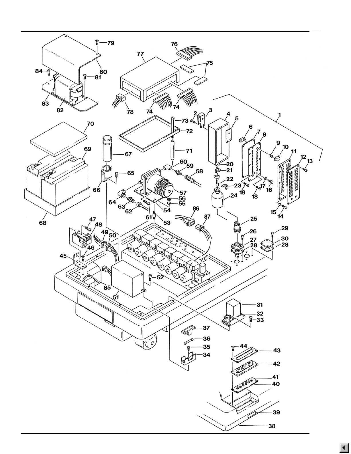
8. ELECTRICAL COMPONENTS, BATTERY MODEL

8. ELECTRICAL COMPONENTS, BATTERY MODEL
Item Part No. Description 6001 6000
1 D5-031-71 PENDANT CONTROL, 6001-KRB ................................................................. 1
D5-031-65 PENDANT CONTROL, (letters) S.N. 6001B-1992-3&L ................................. 1
D5-031-36 PENDANT CONTROL, S.N. 6001B-1992-2&P ............................................. 1
2 D6-032-33 •SCREW, pendant hook, M4x12 .................................................................... 3
3 D5-031-14 •HOOK, pendant............................................................................................. 1
4 D5-031-22 •COVER, rubber ............................................................................................. 1
5 D5-031-34 •INSERT, pendant hook ................................................................................. 1
6 D5-030-23 •MICRO-SWITCH......................................................................................... A/R
7 D5-032-48 •GASKET, micro-switch plate......................................................................... 1
8 D5-031-59 •PLATE, micro-switch mounting ..................................................................... 1
9 D5-031-07 •SPRING, pendant button ............................................................................ A/R
10 •BUTTON, pendant (specify function & S.N.)............................................... A/R
11 D5-031-56 •HOLDER, plastic button ................................................................................ 1
12 D5-031-72 •FACE PLATE, pendant control, 6001-KRB ................................................... 1
D5-031-66 •FACE PLATE, pendant control, S.N. 6001B-1992-3&L ................................ 1
D5-031-57 •FACE PLATE, pendant control, S.N. 6001B-1992-2&P ................................ 1
13 D6-010-80-1 •SCREW, phillips hd., M3x6 ........................................................................... 4
14 D6-010-10-9 •SCREW, phillips hd., M3x15 ......................................................................... 6
15 D5-030-42 •WASHER, special, M3 .................................................................................. 6
16 D5-030-43 •INDICATOR LIGHT, green............................................................................ 1
D5-030-43-1 •INDICATOR LIGHT, amber ........................................................................... 1
17 D5-030-48 •CHROME RING, indicator light ..................................................................... 2
18 D6-032-15 •SCREW, M3x10 ............................................................................................ 2
19 D6-010-109 •SCREW, M3x16 ............................................................................................ 6
20 D5-031-38-1 •STRAIN RELIEF, pendant end ..................................................................... 1
21 D5-031-38 •CORD, pendant control ................................................................................. 1
22 D5-031-38-2 •STRAIN RELIEF, connector end................................................................... 1
23 D6-010-24 •TIE, cable ...................................................................................................... 1
24 D5-030-18 •COVER, cannon connector ........................................................................... 1
25 D5-032-38 •CONNECTOR, cannon (male 24-pin) S.N. 6001B-1992-3&L ....................... 1
D5-030-21 •CONNECTOR, cannon (male 19-pin) S.N. 6001B-1992-2&P ...................... 1
26 D6-032-32 SCREW, phillips hd., M3x8 (plated) ............................................................... 4
27 D5-032-39 CONNECTOR, cannon (female 24-pin) S.N. 6001B-1992-3&L ..................... 1
D5-030-20 CONNECTOR, cannon (female 19-pin) S.N. 6001B-1992-2&P ..................... 1
28 D5-030-46 GASKET, connector ....................................................................................... 2
29 D6-032-10 SCREW, M3x20 ............................................................................................. 4
30 D5-032-21-BT COVER, auxiliary base connector .................................................................. 1
31 D5-032-51 RELAY, switch over........................................................................................ 1
32 D5-032-56 TERMINAL STAND, relay .............................................................................. 1
33 D6-031-45 SCREW, phillips hd., M4x15 .......................................................................... 2
34 D5-031-49 FUSE HOLDER .............................................................................................. 1
35 D6-050-37 SCREW, phillips hd., M4x8 ............................................................................ 1
36 D5-032-42 FUSE, 15amp ................................................................................................. 1
37 D5-031-48 COVER, fuse holder ....................................................................................... 1
38 D1-032-08 COVER, service access, S.N. 6001B-1992-3&L ............................................ 1
D1-031-01 COVER, service access, S.N. 6001B-1992-2&P ........................................... 1
39 D1-032-26 MAGNET, switch cover retaining ................................................................... 1
D6-031-40 HOLDER, magnet, S.N. 6001B-1992-2&P ..................................................... 1
D6-031-41 MAGNET, cover door, S.N. 6001B-1992-2&P ............................................... 1
Page 27
Quantity

Page 28
8. ELECTRICAL COMPONENTS, BATTERY MODEL (CONTINUED)

8. ELECTRICAL COMPONENTS, BATTERY MODEL (CONTINUED)
Item Part No. Description 6001 6000
40 D5-032-67 PLATE, switch mounting, S.N. 6001B-1992-3&L ........................................... 1
41 D5-031-43 SWITCH, toggle, 2 position .......................................................................... A/R
D5-031-44 SWITCH, toggle, 1 position .......................................................................... A/R
42 D5-032-69 COVER, switch assembly .............................................................................. 1
43 D5-031-42 FACE PLATE, 7 switch, S.N. 6001B-1992-2&P ............................................. 1
44 D6-032-31 SCREW, phillips hd., M4x8 ............................................................................ 4
45 D1-032-18 BRACKET, relay mounting, S.N. 6001B-1992-3&L........................................ 1
D1-032-19 BRACKET, relay mounting, S.N. 6001B-1992-2&P ....................................... 1
46 D6-032-20 SCREW, phillips hd., ...................................................................................... 2
47 D6-032-19 BOLT, allen, M4x12........................................................................................ 1
48 D5-032-61 RELAY, thermal.............................................................................................. 1
49 D5-032-60 CONNECTOR, 6-pin, female ......................................................................... 1
50 D5-032-59 CONNECTOR, 6-pin, male ............................................................................ 1
51 D5-032-57 CHARGER, battery, S.N. 6001B-1992-3&L ................................................... 1
D5-031-52 CHARGER, battery, S.N. 6001B-1992-2&P ................................................... 1
D5-031-50 •TRANSFORMER, S.N. 6001B-1992-2&P ..................................................... 1
52 D6-010-70 BOLT, allen, M5x10........................................................................................ 2
53 D4-031-65 ISOLATION MOUNT, motor ........................................................................... 4
54 D1-032-25 PLATE, motor mounting ................................................................................. 1
55 D6-010-77 WASHER, lock, M5 ........................................................................................ 4
56 D6-010-76 NUT, M5 ......................................................................................................... 4
57 D4-031-98 PUMP/MOTOR ASSEMBLY .......................................................................... 1
58 D4-032-64 HOSE, flexible, pump return........................................................................... 1
59 D4-032-63 FITTING ......................................................................................................... 1
60 D4-032-62 90° ELBOW .................................................................................................... 1
61 D6-032-22 BOLT, allen .................................................................................................... 2
62 D4-032-66 TUBE, suction ................................................................................................ 1
63 D4-032-67 FITTING ......................................................................................................... 1
64 D4-032-68 90° ELBOW .................................................................................................... 1
65 D6-010-19 SCREW, phillips hd., M5x10 .......................................................................... 1
66 D1-031-19 BRACKET, capacitor ...................................................................................... 1
67 D5-032-65 CAPACITOR, charging box ............................................................................ 1
68 D1-032-20 TRAY, battery ................................................................................................. 1
69 D5-032-43 BATTERY, 12V, S.N. 6001B-1992-3&L ......................................................... 2
D5-031-37 BATTERY PACK, S.N. 6001-1992-2&P ......................................................... 2
70 D1-032-21 COVER, battery.............................................................................................. 1
D5-031-47 HOLDING FRAME, battery, S.N. 6001B-1992-2&P ....................................... 1
71 D1-032-22 STAND-OFF ................................................................................................... 2
72 D1-032-23 TRAY, relay box ............................................................................................. 1
73 D6-032-21 BOLT, allen, M5x105...................................................................................... 2
74 D5-031-46 CONNECTOR, 16-pin, female ....................................................................... 2
75 D5-032-63 CONNECTOR, 26-pin, female. ...................................................................... 2
D5-032-32 CONNECTOR, 30-pin, female ....................................................................... 2
76 D5-032-27 CONNECTOR, 15-pin, female, -KR models................................................... 1
D5-032-73 WIRE HARNESS, relay box to riser cord, -KR models .................................. 1
77 D5-032-31 RELAY BOX, S.N. 6001B-1992-3&L .............................................................. 1
D5-031-51 RELAY BOX, S.N. 6001B-1992-2&P ............................................................. 1
Page 29
Quantity

Page 30
8. ELECTRICAL COMPONENTS, BATTERY MODEL (CONTINUED)

8. ELECTRICAL COMPONENTS, BATTERY MODEL (CONTINUED)
Item Part No. Description 6001 6000
78 D5-032-64 CONNECTOR, 7-pin, female ......................................................................... 1
79 D6-050-36 BOLT, allen, M5x8.......................................................................................... 2
80 D1-032-16 COVER, transformer ...................................................................................... 1
81 D6-032-17 SCREW, phillips hd., ...................................................................................... 2
82 D5-032-58 TRANSFORMER, battery charger, S.N. 6001B-1992-3&L ............................ 1
83 D1-032-17 PLATE, transformer mounting ........................................................................ 1
84 D6-032-18 BOLT, allen .................................................................................................... 2
85 D5-032-72 WIRE, grounding ............................................................................................ 1
86 D5-030-02 CONNECTOR, 2-pin, male .......................................................................... A/R
87 D5-030-03 CONNECTOR, 2-pin, female ....................................................................... A/R
Page 31
Quantity
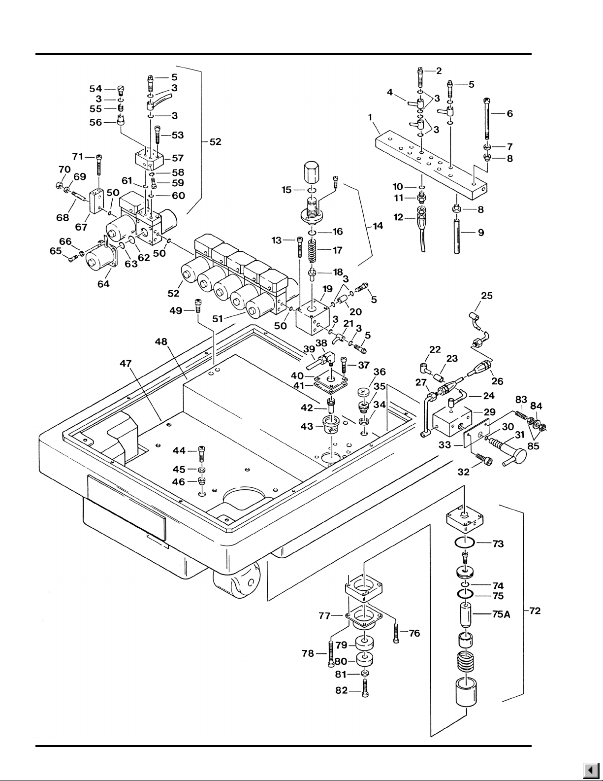
Page 32
9. HYDRAULIC VALVES & FITTINGS

9. HYDRAULIC VALVES & FITTINGS
Item Part No. Description 6001 6000
1 D4-032-23 TERMINAL, plumbing, S.N. 6001N-1992-1&L ............................................... 1 1
D4-031-99 TERMINAL, plumbing, S.N. 6001-1989-5 to S.N. 6001-1991-12 ................... 1
D4-031-99-1 TERMINAL, plumbing, S.N. 6001-1989-5 to S.N. 6001-1991-12 .................... 1
D4-031-17-1 TERMINAL, plumbing, S.N. 6001-1986-3 to S.N. 6001-1989-4 ..................... 1
D4-031-18-1 TERMINAL, plumbing, S.N. 6001-1986-3 to S.N. 6001-1989-4 ...................... 1
D4-031-17 TERMINAL, plumbing, S.N. 6001-1986-2&P ................................................. 1
D4-031-18 TERMINAL, plumbing, S.N. 6001-1986-2&P .................................................. 1
2 D4-010-26 BOLT, plumbing, M6 (long) .......................................................................... A/R A/R
3 D4-010-08 O-RING, P-7 ................................................................................................. A/R A/R
4 OIL LINE, specify function ............................................................................ A/R A/R
5 D4-010-24 BOLT, plumbing, M6 .................................................................................... A/R A/R
6 D6-032-13 BOLT, allen, M6x140...................................................................................... 2 2
7 D6-010-85 WASHER, flat, M6 .......................................................................................... 2 2
8 D6-031-16 BUSHING, isolation ........................................................................................ 4 4
9 D4-032-81 STAND-OFF ................................................................................................... 2 2
10 D4-010-32 PACKING, copper ........................................................................................ A/R A/R
11 D4-010-31 FITTING, flexible hose ................................................................................. A/R A/R
12 HOSE, flexible (specify function) .................................................................. A/R A/R
13 D6-010-65 BOLT, allen, M5x35........................................................................................ 4 4
14 D4-031-23 PRESSURE RELIEF VALVE ......................................................................... 1 1
15 D4-031-67 •O-RING, P-10................................................................................................ 1 1
16 D4-010-51 •O-RING, P-16................................................................................................ 1 1
17 D4-031-12 •SPRING ........................................................................................................ 1 1
18 D4-031-23-1 •VALVE, relief, 5mm dia (steel) S.N. 6000-1989-7&L .................................... 1 1
D4-020-31 •VALVE, relief, 6mm dia (plastic) S.N. 6000-1989-6&P ................................. 1 1
19 D4-031-23-2 •HOUSING, relief valve (5mm dia valve) S.N. 6000-1989-7&L...................... 1 1
D4-031-23-3 •HOUSING, relief valve (6mm dia valve) S.N. 6000-1989-6&P ..................... 1 1
20 D4-010-18 CAP, blind, M6 ............................................................................................... 1 1
21 D4-032-58 OIL LINE, pump outlet, S.N. 6000N-1992-1&L .............................................. 1 1
D4-031-22 OIL LINE, pump outlet, S.N. 6000-1991-12&P............................................... 1 1
22 D4-032-52 OIL LINE......................................................................................................... 1 1
23 D4-032-51 FLEXIBLE TUBE ............................................................................................ 1 1
24 D4-032-50 OIL LINE......................................................................................................... 1 1
25 D4-032-47 OIL LINE......................................................................................................... 1 1
26 D4-032-48 FLEXIBLE HOSE ........................................................................................... 1 1
27 D4-032-49 OIL LINE......................................................................................................... 1 1
29 D4-032-24-1 BLOCK, emergency brake release, S.N. 6001NK-1885&L, 6001NB-114&L,
6001KR-141&L, 6001KRB-041&L, 6000N-139&L.......................................... 1 1
D4-032-24 BLOCK, emergency brake release, S.N. 6001NK-1884&P, 6001NB-113&P,
6001KR-140&P, 6001KRB-040&P, 6000N-138&P ........................................ 1 1
30 D4-010-52 O-RING, P-4 ................................................................................................... 1 1
31 D4-032-25 HANDLE, emergency brake release .............................................................. 1 1
32 D6-010-30 BOLT, allen, M6x20...................................................................................... A/R A/R
33 D4-032-46 SPACER......................................................................................................... 1 1
34 D4-010-37 GASKET, oil filler............................................................................................ 1 1
35 D4-010-38 FITTING, oil filler ............................................................................................ 1 1
36 D4-010-39 CAP, oil filler ................................................................................................... 1 1
37 D6-010-67 BOLT, allen, M5x15........................................................................................ 4 4
Page 33
Quantity

Page 34
9. HYDRAULIC VALVES & FITTINGS (CONTINUED)

9. HYDRAULIC VALVES & FITTINGS (CONTINUED)
Item Part No. Description 6001 6000
38 D4-030-12 FITTING, hydraulic motor/oil tank 90° ............................................................ 2 2
39 D4-030-03 OIL LINE, supply ............................................................................................ 1 1
40 D4-031-14 COVER, oil tank ............................................................................................. 1 1
41 D4-031-13 GASKET, oil tank cover.................................................................................. 1 1
42 D4-030-19 TUBE, induction ............................................................................................. 1 1
43 D4-031-11 STRAINER, oil................................................................................................ 1 1
44 D6-010-30 BOLT, allen, M6x20........................................................................................ 3 3
45 D6-031-15 WASHER........................................................................................................ 3 3
46 D1-031-12 BUSHING, isolation ........................................................................................ 6 6
47 D4-032-56 PLATE, oil tank receiving, S.N. 6000N-1992-1&L .......................................... 1 1
D4-032-57 PLATE, oil tank receiving, battery model, S.N. 6001B-1992-3&L .................. 1
D4-031-13 PLATE, oil tank receiving, S.N. 6000-1991-12&P .......................................... 1 1
48 D4-031-63 RESERVOIR, oil tank, S.N. 6000N-1992-1&L ............................................... 1 1
D4-031-10 RESERVOIR, oil tank, S.N. 6000-1991-12&P................................................ 1 1
49 D6-010-51 BOLT, allen, M6x10........................................................................................ 2 2
50 D4-010-52 O-RING, P-4 ................................................................................................. A/R A/R
51 D4-031-21 ELECTRO/MINI VALVE ASSEMBLY (3-way), 120VAC (elevation)............. A/R A/R
D4-032-92 ELECTRO/MINI VALVE ASSEMBLY (3-way), 120VAC (brake) .................. A/R A/R
D4-032-59 ELECTRO/MINI VALVE ASSEMBLY (3-way), 24VDC (elevation) .............. A/R A/R
D4-032-93 ELECTRO/MINI VALVE ASSEMBLY (3-way), 24VDC (brake) .................... A/R A/R
52 D4-030-02 ELECTRO/MINI VALVE ASSEMBLY (4-way), 120VAC .............................. A/R A/R
D4-032-60 ELECTRO/MINI VALVE ASSEMBLY (4-way), 24VDC ................................ A/R A/R
53 D6-010-65 •BOLT, allen, M5x35 ...................................................................................... 2 2
54 D4-010-41 •PLUG, cap..................................................................................................... 2 2
55 D4-010-42 •SPRING, return ............................................................................................. 2 2
56 D4-010-25 •VALVE, non-return ........................................................................................ 2 2
57 D4-010-43 •VALVE BLOCK, 4-way .................................................................................. 6 6
D4-020-23 •VALVE BLOCK, 3-way .................................................................................. 2 2
58 D4-010-20 •O-RING, P-3.................................................................................................. 2 2
59 D4-010-44 •VALVE, needle, speed control ...................................................................... 2 2
60 D4-010-19 •O-RING, P-6.................................................................................................. 2 2
61 D4-010-01 •O-RING, P-8.................................................................................................. 2 2
62 D4-010-51 •O-RING, P-16................................................................................................ 2 2
63 D4-010-14 •O-RING, P-12................................................................................................ 2 2
64 D5-030-34 •SOLENOID, 120VAC .................................................................................... 2 2
D5-031-35 •SOLENOID, 24VDC ...................................................................................... 2 2
65 D6-010-79 •SCREW, phillips hd., M3x5 ........................................................................... 8 8
66 D6-010-78 •WASHER, lock, M3 ....................................................................................... 8 8
67 D4-010-40 CAP, end ........................................................................................................ 1 1
68 D4-010-19 STUD,M5........................................................................................................ 2
D6-031-20 STUD, M5........................................................................................................ 2
69 D6-010-77 WASHER, lock, M5 ........................................................................................ 4 4
70 D6-010-76 NUT, M5 ......................................................................................................... 4 4
71 D6-010-64 BOLT, allen, M5x40........................................................................................ 2 2
72 D4-035-37 CYLINDER ASSEMBLY, brake, S.N. 6001N- -1771&L, 6001NB- -108&L,
6001KR- -051&L, 6001KRB- -016&L, 6000- -116&L...................................... 4 4
D4-031-60 CYLINDER ASSEMBLY, brake, single action, S.N. 6000-1989-5&L ............. 4 4
D6-031-50 BRAKE CYLINDER REBUILD KIT (for D4-031-60) ..................................... A/R A/R
Page 35
Quantity

Page 36
9. HYDRAULIC VALVES & FITTINGS (CONTINUED)

9. HYDRAULIC VALVES & FITTINGS (CONTINUED)
Item Part No. Description 6001 6000
73 D4-031-47 •O-RING, G-35 ............................................................................................... 1 1
74 D4-010-02 •O-RING, P-14................................................................................................ 1 1
75 D4-031-66 •SCRAPER, piston ......................................................................................... 1 1
75A D4-031-68 •RAM, brake cylinder, for D4-031-60.............................................................. 1 1
76 D6-031-25 •BOLT, allen, M5x65 ...................................................................................... 2 2
77 D4-032-61 COVER, ram .................................................................................................. 4 4
78 D6-031-26 BOLT, allen, M6x95....................................................................................... 16 16
D6-031-20 BOLT, allen, M6x85 ....................................................................................... 16 16
79 D4-031-95-1 SEAT, brake rubber........................................................................................ 4 4
80 D4-031-96 PAD, brake, self-leveling, hard ....................................................................... 2 2
D4-031-97 PAD, brake, self-leveling, soft ........................................................................ 2 2
81 D6-010-36 WASHER........................................................................................................ 4 4
82 D6-010-30 BOLT, allen, M6x20........................................................................................ 4 4
83 D6-032-41 SCREW, set, ................................................................................................ A/R A/R
84 D6-010-40 WASHER, M6............................................................................................... A/R A/R
85 D6-010-41 NUT, M6 ....................................................................................................... A/R A/R
Page 37
Quantity
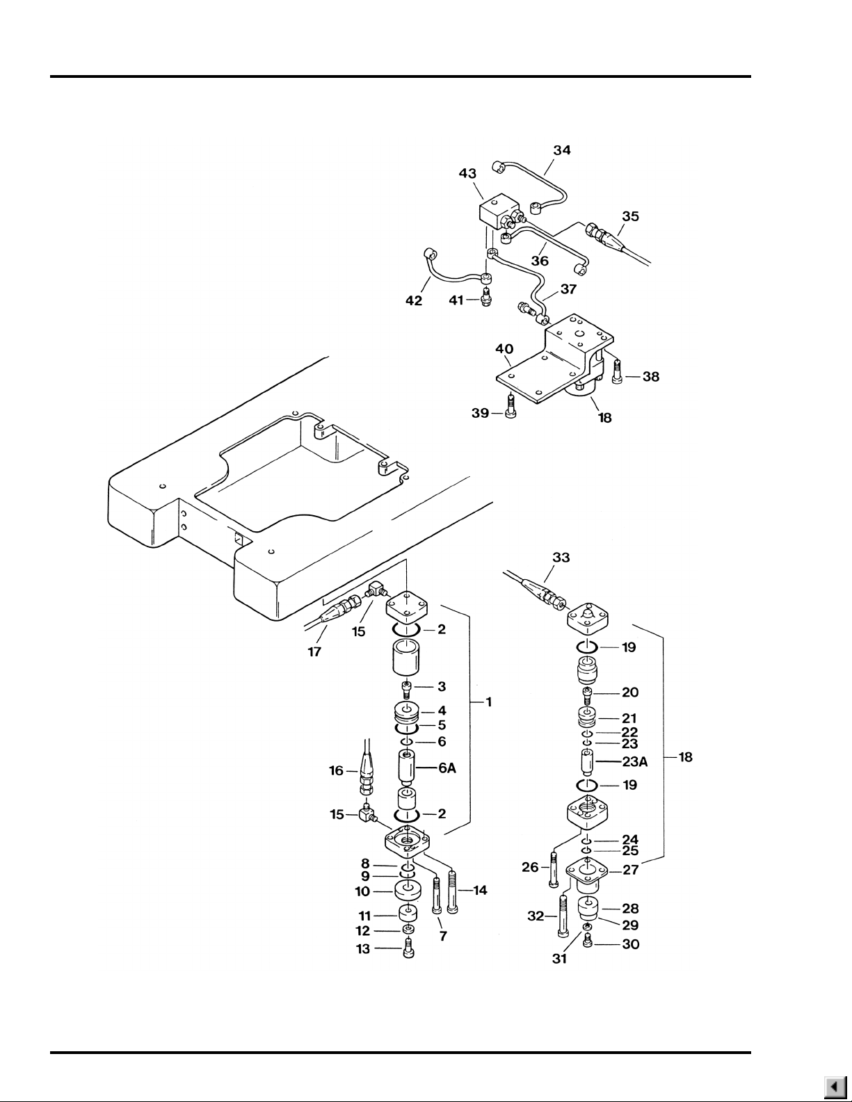
Page 38
10. BRAKE SYSTEMS, S.N. 6000-1989-4&P

10. BRAKE SYSTEMS, S.N. 6000-1989-4&P
Item Part No. Description 6001 6000
1 D4-031-34-1 CYLINDER ASSEMBLY, brak e , f r o n t and rear, S.N. 6000-1986-3 to
S.N. 6000-1989-4 ............................................................................................. 4 4
D4-031-34 CYLINDER ASSEMBLY, rear brake, S.N. 6000-1986-3&P ........................... 2 2
2 D4-010-09 •O-RING, G-50 ............................................................................................... 4 4
3 D6-010-53 •BOLT, allen, M8x20 ...................................................................................... 1 1
4 D4-031-26 •PISTON, cylinder .......................................................................................... 1 1
5 D4-010-54 •O-RING, P-34................................................................................................ 1 1
6 D4-010-56 •O-RING, P-10A ............................................................................................. 1 1
6A D4-031-27 •RAM, brake cylinder ...................................................................................... 1 1
7 D6-031-17 •BOLT, allen, M6x70 ...................................................................................... 2 2
8 D4-031-29 •SEAL RING, PS-25 ....................................................................................... 1 1
9 D4-031-30 •SCRAPER, SER-25 ...................................................................................... 1 1
10 D4-010-95 SEAT, brake rubber........................................................................................ 2 2
11 D1-010-12 PAD, brake rubber.......................................................................................... 2 2
12 D6-010-36 WASHER, brake rubber ................................................................................. 2 2
13 D6-010-30 BOLT, allen, M6x20........................................................................................ 2 2
14 D6-031-18 BOLT, allen, M8x90........................................................................................ 8 8
15 D4-010-29 FITTING, hydraulic, 90° elbow ....................................................................... 4 4
16 D4-031-09 HOSE, flexible, 690mm .................................................................................. 1 1
D4-031-03 HOSE, flexible, 530mm .................................................................................. 1 1
17 D4-031-05 HOSE, flexible, 560mm .................................................................................. 1 1
D4-031-07 HOSE, flexible, 370mm .................................................................................. 1 1
D6-031-49 BRAKE CYLINDER REBUILD KIT ............................................................... A/R A/R
18 D4-031-25 CYLINDER ASSEMBLY, front brake, S.N. 6000-1986-3&P .......................... 2 2
D6-031-48 BRAKE CYLINDER REBUILD KIT ............................................................... A/R A/R
19 D4-031-47 •O-RING, G-35 ............................................................................................... 2 2
20 D6-010-17 •BOLT, allen, M8x15 ...................................................................................... 1 1
21 •PISTON, cylinder .......................................................................................... 1 1
22 D4-010-12 •O-RING, P-24................................................................................................ 1 1
23 D4-010-56 •O-RING, P-10A ............................................................................................. 2 2
23A D4-031-34-2 •RAM, brake cylinder, for D4-031-34-1 .......................................................... 1 1
24 D4-031-45 •SEAL RING, PS-20 ....................................................................................... 1 1
25 D4-031-46 •SCRAPER, SER-20 ...................................................................................... 1 1
26 D6-031-22 •BOLT, allen, M5x55 ...................................................................................... 2 2
27 D4-031-48 COVER, ram .................................................................................................. 1 1
D4-031-48-1 COVER, ram, short ........................................................................................ 1 1
28 D4-010-95-1 SEAT, brake rubber (use opposite adj. feet) .................................................. 2 2
D4-031-32 ADJUSTABLE FOOT, brake cylinder ............................................................. 2 2
D4-031-95 SEAT, brake rubber, S.N. 6000-1989-2 to S.N. 6000-1989-4 ........................ 4 4
29 D4-031-56 PAD, brake cylinder adj. foot .......................................................................... 2 2
D4-031-96 PAD, hard, S.N. 6000-1989-2&L .................................................................... 2 2
D4-031-97 PAD, soft, S.N. 6000-1989-2&L ..................................................................... 2 2
30 D6-010-30 BOLT, allen, M6x20........................................................................................ 4 4
31 D6-010-36 WASHER, brake rubber ................................................................................. 4 4
32 D6-031-20 BOLT, allen, M6x85........................................................................................ 4 4
33 D4-031-54 HOSE, flexible ................................................................................................ 2 2
D4-031-55 HOSE, flexible ................................................................................................ 2 2
34 D4-031-53 OIL LINE (move left)....................................................................................... 1 1
35 D4-031-08 HOSE, flexible, 570mm .................................................................................. 2 2
Page 39
Quantity

Page 40
10. BRAKE SYSTEMS, S.N. 6000-1989-4&P (CONTINUED)

10. BRAKE SYSTEMS, S.N. 6000-1989-4&P (CONTINUED)
Item Part No. Description 6001 6000
36 D4-031-51 OIL LINE (move right) .................................................................................... 1 1
37 D4-031-50 OIL LINE (set right) ........................................................................................ 1 1
38 D6-031-21 BOLT, allen, M8x35........................................................................................ 5 5
39 D6-010-96 BOLT, allen, M10x20...................................................................................... 8 8
40 D4-031-35 BRACKET ...................................................................................................... 2 2
41 D4-010-24-1 BOLT, plumbing ........................................................................................... A/R A/R
42 D4-031-52 OIL LINE (set left)........................................................................................... 1 1
43 D4-031-49 TERMINAL, plumbing..................................................................................... 1 1
Page 41
Quantity
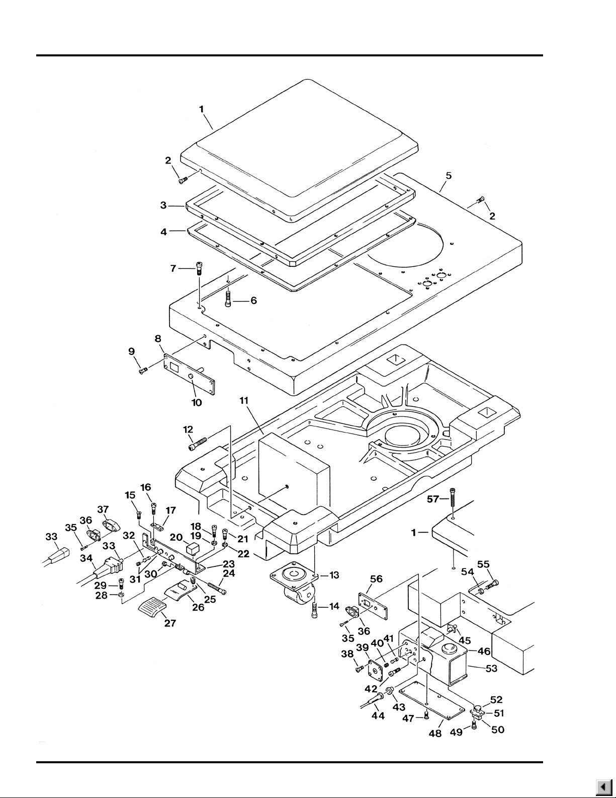
Page 42
11. BASE & POWER SWITCH

11. BASE & POWER SWITCH
Item Part No. Description 6001 6000
1 D1-031-36 COVER, service access, S.N. 6000N-111&L, 6001N-1771&L,
6001KR-046&L ............................................................................................... 1 1
D1-032-07 COVER, service access, S.N. 6000N-1992-1 to-110 S.N. 6001N-1 to -1771,
6001KR-045&P .............................................................................................. 1 1
D1-031-11 COVER, service access, S.N. 6000-1991-12&P ............................................ 1 1
D1-031-38 COVER, service access, battery model, S.N. 6001NB-108&L,
6001KRB-011&L ............................................................................................ 1 1
D1-032-05 COVER, service access, battery model, S.N. 6001B-1992-3 to 107 ............. 1
D1-031-01 COVER, service access, battery model, S.N. 6001B-1992-2&P .................... 1
2 D6-050-37 SCREW, phillips hd., M4x8 ............................................................................ 4 4
3 D1-031-37 FRAME, S.N. 6000N-1995-9&L ..................................................................... 1 1
D1-032-09 FRAME, S.N. 6000N-1992-1 to 1995-8 .......................................................... 1 1
D1-032-03 FRAME, S.N. 6000-1991-12&P ...................................................................... 1 1
4 D1-032-10 GASKET, S.N. 6000N-1992-1&L ................................................................... 1 1
D1-032-04 GASKET, S.N. 6000-1991-12&P .................................................................... 1 1
5 D1-032-11 HOUSING, base, S.N. 6000N-1992-1&L ....................................................... 1 1
6 D6-010-67 BOLT, allen, M5x15....................................................................................... 10 10
7 D6-010-51 BOLT, allen, M6x10........................................................................................ 2 2
8 D1-032-12 PLATE, fuse cover ......................................................................................... 1 1
D1-032-13 PLATE, fuse cover, battery model.................................................................. 1 1
9 D6-032-08 SCREW, M4x6, black ..................................................................................... 4 4
10 D5-031-53 LIGHT, indicator, battery model ..................................................................... 1 1
11 D1-032-27 BALANCE WEIGHT, S.N. 6001N-1992-9-1454&L......................................... 1 1
D1-032-14 BALANCE WEIGHT, S.N. 6001N-1992-9-1453&P ........................................ 1 1
12 D6-010-53 BOLT, allen, M8x20........................................................................................ 2 2
13 D1-010-30 CASTER, 105HB-P ........................................................................................ 4 4
14 D6-010-96 BOLT, allen, M10X20 .................................................................................... 16 16
15 D6-010-16 SCREW, phillips hd.,M5x6 ............................................................................. 1 1
16 D6-032-06 BOLT, allen, M4x20........................................................................................ 2 2
17 D5-032-37 RETAINER, power cord ................................................................................. 1 1
18 D6-010-30 BOLT, allen, M6x20........................................................................................ 2 2
19 D6-010-41 NUT, M6 ......................................................................................................... 2 2
20 D5-030-19 SWITCH, main power..................................................................................... 1 1
21 D6-010-51 BOLT, allen, M6x10........................................................................................ 3 3
22 D6-010-40 WASHER, lock, M6 ........................................................................................ 3 3
23 D5-032-52-3 BRACKET, On/Off switch, S.N. 6000N-1992-1&L ......................................... 1 1
D5-032-52-2 BRACKET, On/Off switch, battery model, S.N. 6001B-1992-3&L .................. 1
24 D6-032-09 BOLT, allen, M5x50........................................................................................ 1 1
25 D6-032-12 SPRING (#89) ................................................................................................ 1 1
26 D5-032-53-1 SWITCH PEDAL, On/Off switch..................................................................... 1 1
27 D5-032-54 COVER, switch pedal ..................................................................................... 1 1
28 D6-010-59 NUT, M4 ......................................................................................................... 1 1
29 D6-032-06 BOLT, allen, M4x20........................................................................................ 1 1
30 D6-010-76 NUT, M5 ......................................................................................................... 1 1
31 D1-030-15 FUSE HOLDER .............................................................................................. 2 2
D5-032-74 FUSE HOLDER, 250V, 15A (9/97&L) ............................................................ 1 1
32 D5-032-41 FUSE, 10A ..................................................................................................... 2 2
33 D5-032-34 POWER CORD ASSEMBLY .......................................................................... 1 1
D5-031-08 POWER CORD ASSEMBLY, battery model .................................................. 1 1
Page 43
Quantity

Page 44
11. BASE & POWER SWITCH (CONTINUED)

11. BASE & POWER SWITCH (CONTINUED)
Item Part No. Description 6001 6000
34 D5-032-35 STRAIN RELIEF............................................................................................. 1 1
35 D6-032-10 SCREW, M3x20 ............................................................................................. 2 2
36 D5-031-54-1 CONNECTOR, power cord, battery model..................................................... 1 1
37 D5-031-54-2 SPACER, power cord connector, battery model ............................................ 1 1
38 D6-010-57-1 SCREW, phillips hd., M4x10 (plated) ............................................................. 4 4
39 D1-031-24 PLATE, fuse cover ......................................................................................... 1 1
D1-031-25 PLATE, fuse cover, battery model.................................................................. 1 1
40 D1-030-15 FUSE HOLDER .............................................................................................. 1 1
41 D5-030-10 FUSE, 8 amp .................................................................................................. 1 1
D5-031-60 FUSE, 5 amp, battery model .......................................................................... 1
42 D6-010-67 BOLT, allen, M5x15........................................................................................ 2 2
43 D5-031-27 GROMMET, strain relief ................................................................................. 1 1
44 D5-030-01 POWER CORD .............................................................................................. 1 1
D5-030-08 STRAIN RELIEF ............................................................................................. 1 1
45 D1-031-29 PLATE, fuse holder mount ............................................................................. 1 1
46 D1-031-30 COVER, rubber, electrical enclosure ............................................................. 1 1
D1-031-35 COVER, rubber, electrical enclosure, battery model ...................................... 1
47 D6-050-37 SCREW, phillips hd., M4x8 ............................................................................ 6 6
48 D1-031-33 COVER, electrical enclosure, bottom ............................................................. 1 1
49 D6-010-70 BOLT, allen, M5x10........................................................................................ 2 2
50 D5-030-19 SWITCH, main power..................................................................................... 1 1
51 D1-031-32 PLATE, switch mounting ................................................................................ 1 1
52 D5-031-28 HEAD, power switch....................................................................................... 1 1
53 D1-031-31 ENCLOSURE, electrical ................................................................................. 1 1
D1-031-34 ENCLOSURE, electrical, battery model ......................................................... 1
54 D6-010-77 WASHER, lock, M5 ........................................................................................ 4 4
55 D6-010-37 BOLT, allen, M5x20........................................................................................ 4 4
56 D1-031-02 PLATE, charging lamp, battery model............................................................ 1
57 D6-031-14-1 BOLT, allen, M8x55 (plated) .......................................................................... 4 4
Page 45
Quantity

Page 46
12. OPTIONAL KIDNEY LIFT ASSEMBLY

12. OPTIONAL KIDNEY LIFT ASSEMBLY
Item Part No. Description 6001 6000
1 1-010-06-8P PAD, back/seat section .................................................................................. 1
2 D3-031-65 TOP, back section, S.N. 6001-1990-7&L ....................................................... 1 1
D3-031-36 TOP, back section, S.N. 6001-1990-6&P ....................................................... 1 1
3 D3-031-37 TOP, seat section ........................................................................................... 1
D3-031-32 TOP, seat section ............................................................................................ 1
4 D3-010-19 SCREW, top retaining flathead (plated) ....................................................... A/R A/R
D6-031-52 SCREW, roundhead ..................................................................................... A/R A/R
5 D3-031-38 TOP, kidney lift ............................................................................................... 1 1
D3-031-77 TOP, kidney lift ............................................................................................... 1 1
6 D3-031-39 PIVOT ASSEMBLY ........................................................................................ 2 2
7 D6-031-24 PIN, roll, 5x12 ................................................................................................. 2 2
8 D3-031-40 SHAFT, elevation ........................................................................................... 2 2
9 D6-031-03 CIRCLIP ......................................................................................................... 2 2
10 D6-031-04 SPACER....................................................................................................... A/R A/R
11 D3-031-41-1 HOUSING, gear, right, S.N. 6001-1986-7-277&L .......................................... 1 1
D4-031-41 HOUSING, gear, right, S.N. 6001-1986-7-276&P .......................................... 1 1
D4-031-42-1 HOUSING, gear, left, S.N. 6001-1986-7-277&L ............................................. 1 1
D4-031-42 HOUSING, gear, left, S.N. 6001-1986-7-276&P ............................................ 1 1
12 D6-010-32 SCREW, set, M4x15 ...................................................................................... 2 2
13 D6-031-05 SCREW, phillips, M4x10 ................................................................................ 8 8
14 D3-031-43 COVER, gear housing, right ........................................................................... 1 1
D3-031-44 COVER, gear housing, left ............................................................................. 1 1
15 D3-031-45 GEAR ............................................................................................................. 2 2
16 D3-031-46 SHAFT, gear .................................................................................................. 2 2
17 D3-031-47 GEAR ............................................................................................................. 2 2
D3-031-47-1 GEAR ............................................................................................................. 2 2
18 D3-031-66 BEARING, kidney lift gear .............................................................................. 1 1
19 D3-031-48 THRUST BEARING ASSEMBLY ................................................................... 2 2
20 D3-031-49 GEAR ASSEMBLY, belt drive ........................................................................ 2 2
21 D6-050-33 PIN, roll, 5x20 ................................................................................................. 2 2
22 D3-031-50 BELT, drive..................................................................................................... 2 2
23 D6-031-07 BOLT, special ................................................................................................. 2 2
24 D6-010-40-1 LOCKWASHER, M6 (plated).......................................................................... 6 6
25 D6-010-38 BOLT, allen, M6x15........................................................................................ 6 6
26 D3-031-51 BLOCK, guide ................................................................................................ 2 2
27 D6-031-59-1 BOLT, allen, M6x40 (plated) .......................................................................... 4 4
28 D3-031-52 SHAFT, gear .................................................................................................. 2 2
29 D6-050-33 PIN, roll, M5x20, S.N. 6001-1994-7-1694&L .................................................. 4 4
D6-031-09 PIN, tapered, S.N. 6001-1994-7-1693&P ....................................................... 4 4
30 D3-031-53 GEAR, drive ................................................................................................... 2 2
31 D3-031-54 SHAFT, gear drive.......................................................................................... 1 1
32 D6-031-10 SPACER....................................................................................................... A/R A/R
33 D6-031-11 PIN, roll, 5x17 ................................................................................................. 1 1
34 D3-031-60 HANDLE ASSEMBLY, K-lift crank ................................................................. 1 1
35 D3-031-56 •HANDLE, K-lift crank..................................................................................... 1 1
36 D6-010-28-1 •BOLT, allen, M5x6 (plated) ........................................................................... 1 1
37 D6-031-12 •WASHER, flat, M5 (plated) ........................................................................... 1 1
38 D3-010-17 KNOB, head rest ............................................................................................ 2 2
Page 47
Quantity

Page 48
12. OPTIONAL KIDNEY LIFT ASSEMBLY (CONTINUED)

12. OPTIONAL KIDNEY LIFT ASSEMBLY (CONTINUED)
Item Part No. Description 6001 6000
39 D3-031-57 COVER, gear housing .................................................................................... 2 2
40 D6-031-13 SCREW, phllips, M4x8 ................................................................................... 6 6
41 D3-031-58-1 GEAR ............................................................................................................. 2 2
42 D3-031-59 FRAME, back section, beige .......................................................................... 1 1
D3-031-59-S FRAME, back section, silver .......................................................................... 1 1
43 D3-031-62 SIDE RAIL, back section, right (w/ kidney lift), 445mm .................................. 1 1
D3-031-63 SIDE RAIL, back section, left (w/ kidney lift), 445mm .................................... 1 1
44 D3-031-70 AXIS, back section (w/ kidney lift) .................................................................. 2 2
45 D6-010-76-1 NUT, M5 ......................................................................................................... 2 2
46 D6-010-77-1 WASHER, Lock, M5 ....................................................................................... 2 2
47 D3-031-61-L BRACKET, crank storage............................................................................... 1 1
48 D6-010-70 BOLT, allen, M5x10 (crank brkt. mount) ........................................................ 2 2
D6-010-67-1 BOLT, allen, M5x15 (crank brkt. mount) ........................................................ 2 2
Page 49
Quantity

Page 50
Item Part No. Description Qty.
6-050-02 GAUGE, oil pressure...................................................................................................A/R
D6-010-20 WRENCH, spanner .....................................................................................................A/R
D6-010-89 GREASE, slider .........................................................................................................2.8 oz
D6-010-90 OIL, hydraulic ...............................................................................................................Qt
D6-031-50 BRAKE CYLINDER REBUILD KIT (for D4-031-60) ....................................................A/R
D6-031-48 BRAKE CYLINDER REBUILD KIT (for D4-031-25) ....................................................A/R
D6-031-49 BRAKE CYLINDER REBUILD KIT (for D4-031-34 & D4-031-34-1) ............................A/R
D4-010-00 O-RING KIT .................................................................................................................A/R
D6-031-46 DECAL SET, 6000 series ............................................................................................A/R
D6-031-47 DECAL SET, 6001 series ............................................................................................A/R
SPECIAL TOOLS & MAINTENANCE ITEMS

5000 36th Street S.E., Grand Rapids, MI 49512
1-800-SKYTRON or 1-616-957-0500 • FAX 1-616-957-5053
 Loading...