


SURGICAL T ABLE
OPERAT ORS MANU AL
REV 6/06
3600B UltraSlide

Page 1
TABLE OF CONTENTS
Title Page
EQUIPMENT LABELS AND SPECIFICATIONS..................................................................................2
3600B UltraSlide General Purpose Surgical Table Specifications.......................................................3
SPECIAL USER ATTENTION..............................................................................................................4
SECTION I INTRODUCTION..............................................................................................................10
1-1. General.............................................................................................................................10
1-2. Power Requirements........................................................................................................10
1-3. Pendant Control Unit ........................................................................................................11
1-4. Floor Lock/Brake System .................................................................................................11
SECTION II OPERATION...................................................................................................................12
2-1. Electrical Power.................................................................................................................12
2-2. AC 120V Operation ...........................................................................................................12
2-3. Battery Operation ..............................................................................................................13
2-4. Automatic Shut-Off............................................................................................................13
2-5. Charging the Battery .........................................................................................................14
2-6. Positioning Functions ........................................................................................................15
a. Floor Lock/Brake system.............................................................................................15
b. Trendelenburg .............................................................................................................16
c. Lateral Tilt ....................................................................................................................16
d. Back Section................................................................................................................16
e. Elevation......................................................................................................................17
f. Top Slide .....................................................................................................................17
g. Leg Section..................................................................................................................18
h. Flex Positioning ...........................................................................................................18
i. Kidney Lift....................................................................................................................19
j. Return To Level ...........................................................................................................19
k. Beach Chair .................................................................................................................19
2-7. Emergency Back-up controls ............................................................................................20
2-8. Emergency Brake Release................................................................................................21
2-9. Head Section.....................................................................................................................22
2-10. Leg and Back Section Removal ........................................................................................22
2-11. Positioning.........................................................................................................................23
SECTION III MAINTENANCE.............................................................................................................26
3-1. Preventive Maintenance...................................................................................................26
3-2. Cleaning Recommendations ............................................................................................26
3-3. Service .............................................................................................................................27
REV 6/06
Although current at the time of publication, SKYTRON’s policy of continuous development makes this
manual subject to change without notice.

Page 2
TYPE B
EQUIPMENT
EQUIPMENT LABELS AND SPECIFICATIONS
INDICATES DANGEROUS VOLTAGE, 120 V, 60 Hz
CLASS I DEFIBRILLATION PROOF, TYPE B EQUIPMENT- IPX4 RATED.
INTERNALLY POWERED EQUIPMENT
PROTECTIVE GROUNDING.
IN ORDER TO ENSURE PROPER GROUNDING RELIABILITY,
THIS TABLE MUST BE CONNECTED TO A PROPERLY GROUNDED
HOSPITAL GRADE OUTLET.
N
IPX4
V
A
HZ
CONNECTION FOR NEUTRAL CONDUCTOR SUPPLIED
UNIT TO BE USED ONLY IN SPECIFIED ENVIRONMENTAL CONDITIONS
TEMPERATURE: 15˚ - 30˚ C (60˚ - 85˚ F)
HUMIDITY: 30% - 60% RELATIVE HUMIDITY, NON CONDENSING
AC VOLTAGE
ENCLOSURE CLASS
VOLTAGE RATING OF THE UNIT
AMPERAGE RATING OF THE UNIT
FREQUENCY OF THE UNIT
ATTENTION, CONSULT MANUAL FOR FURTHER INSTRUCTIONS.
INDICATES SPECIAL USER ATTENTION.
POWERED BY AC VOLTAGE
POWERED BY BATTERY
BATTERY TYPE:
SEALED
LEAD ACID 12V, VALVE REGULATED
16AH, 10HR (530W/10MIN)
15 AMP INTERNAL CIRCUIT BREAKER
15A

Electrical Specifications
Power requirements
Current Leakage
Power Cord
120 VAC, 60Hz, 450 Watts
Less than 100 micro amps
15 feet w/hospital grade
connector (removable)
12-1/2"
18-1/4" 25" 23"
14-1/2"
19-3/4"
5-3/4"
3"
82"
TOP VIEW
90˚
60˚
14-1/2"
40-3/4"
SIDE VIEW
8-3/4"
5-3/4"
19"
22"
42-1/2" MAX
24" MIN
END VIEW
ENTELA CERTIFIED
TO UL2601-1
CAN/CSA601.1, IEC 60601-2-46
SERIAL NUMBER TAG
3600B UltraSlide General Purpose Surgical Table Specifications
Page 3

Page 4
SPECIAL USER ATTENTION
Prior to use, all personnel that may operate this
table must be instructed in the correct operational procedures. This table is designed for
use by trained and qualified personnel for human medical purposes only.
Initial use should not begin until after the users
have been instructed by the manufacturer's
representative.
A routine instructional program must be implemented by the facility for proper usage instructions for all personnel that may operate this
table.
The maximum lifting capacity of the 3600B
Ultraslide table is 1,000 pounds and the maximum articulation weight capacity is 800 pounds.
When lifting or articulating large patients, pay
close attention to the patient position as well as
the positioning guidelines and limitations listed
in the operation instructions.
The extreme positioning capabilities of the 3600B
UltraSlide Table requires special attention for possible interference points when using multiple function positioning. As with the operation of any
surgical table, a certain amount of care should be
exercised to position the patient safely. Although
the thick pads and sheets substantially protect the
patient, pinch points, located at the joints of the top
section should always be considered. BE SURE
THAT THE ARMS, HANDS AND FINGERS OF
THE PATIENT AND THOSE OF THE OPERATING ROOM PERSONNEL ARE CLEAR OF ALL
MOVING PARTS BEFORE MOVING THE TABLE.
Proper restraints should always be used for patient
safety.
In general, common sense will dictate when there
is a potential hazard.
The following precautions should be reviewed
by all personnel prior to operating the table.
WARNING
Indicates a possibility of personal injury.
CAUTION
Indicates a possibility of damage to
equipment.
NOTE
Indicates important facts or helpful hints.
Do not use worn or damaged accessories, they
represent an injury hazard.
Remove possible obstacles before lowering or
tilting the operating table
Certain accessories such as the Uro-Drain Tray,
Armboards and X-Ray top can be damaged when
changing the position of the table top sections.
Always look first to see if a desired movement is
going to interfere with any accessories in use.
The operator has the ultimate responsibility of
preventing damage to the table and surrounding
equipment or possible injury to the patient or staff.
The operator must ensure proper positioning is
maintained to prevent compromising respiration,
nerve pathways or circulation.
Do not place objects on the base of the table, a
danger of damage exists during positioning.
Use caution when articulating the table top, pinch
hazards exist.

SPECIAL USER ATTENTION
NOTE
Activating any function button will activate the brake system. Using the TABLE
UP function to set the brakes provides
a visual assurance that the brakes are
locked without altering the table position, except when emergency brake is
released.
WARNING
Possible explosion hazard exists if table
is used in the presence of FLAMMABLE
ANESTHETICS.
Page 5
NOTE
Turning the Main Power Switch ON will
change the table operation to 120 VAC
power.
NOTE
When the red light starts to blink (indicating low power in battery) the table
will operate for approximately 5 continuous minutes, typically long enough
to use the table for the rest of the day.
NOTE
NOTE
An equalization terminal is located under the main power panel. This is provided as an alternate pathway to reduce the risk of static shock hazards.
Always follow recommended grounding procedures to ensure patient and
staff safety.
NOTE
The table will operate correctly on battery power with the power cord connected to a wall outlet or disconnected.
NOTE
Battery Operation must be turned OFF
at the pendant control. It cannot be
turned OFF using the main power
switch.
The charging system operates ONLY
when the table is in AC120V operation
mode.
NOTE
The table can be operated on 120VAC
power while the battery is being recharged.
NOTE
If the table is stored for a period greater
than 6 months, the batteries should be
removed and stored in a dry, clean condition at a storage temperature of 68° F
(20° C). Batteries should be recharged
every 6 months of product storage.

Page 6
SPECIAL USER ATTENTION
WARNING
•DO NOT unlock brakes when a patient
is on the table. An uneven patient
weight load may cause instability.
•If circumstances demand table brakes
to be unlocked, the patient must be
centered and evenly distributed on the
table top (i.e. supine or prone position)
with the table lowered to its lowest
height position. The maximum patient
weight should not exceed 500 pounds.
Table top slide must be centered (indicated by a green LED light on the
pendant control) prior to unlocking
brakes. Patient's head must be on the
head section. Head section must be
attached in its normal orientation to the
table's back section.
•Prior to unlocking brakes, check for
obstructions on the floor that might
prevent the table from moving smoothly
to new location. Relock the brakes immediately once the final position is
reached and before commencing surgery. Table brakes should remain locked
at all times if patient weight exceeds
500 pounds.
WARNING
To maximize patient safety, utilize
proper restraint methods during extreme
lateral tilt positioning.
NOTE
If the table top is slid toward the foot
end, the back section will not go below
horizontal. An audible alarm will sound.
NOTE
To prevent damage to the kidney lift, a
safety interlock prevents the back section from going more than 45° above
horizontal if the kidney lift is not all the
way down. An audible alarm will sound.
NOTE
If the leg section is positioned more
than 45° below horizontal, the top will
not slide toward the head end. An
audible alarm will sound.
NOTE
With an evenly distributed patient weight
load, all table positioning functions will
operate smoothly and quietly with a
patient weight of up to 800 pounds.
WARNING
To maximize patient safety, utilize
proper restraint methods during extreme
Trendelenburg positioning.
NOTE
If the leg section is below horizontal,
slide toward head is limited to 7-1/2"
NOTE
If the back section is positioned below
horizontal, the top will not slide toward
the foot end. An audible alarm will
sound.

SPECIAL USER ATTENTION
Page 7
CAUTION
The Leg section may hit the table base
or the floor if both the leg and elevation
systems are placed in their full down
position.
NOTE
If the top is slid toward the head end
less than 7-1/2", the leg section will only
go down 45°. An audible alarm will
sound. If the top is slid toward the head
end more than 7-1/2", the leg section
will not go below horizontal.
NOTE
If the top is slid toward the foot end, the
FLEX function will not operate. An
audible alarm will sound.
CAUTION
The safety interlock system is not operational when the emergency backup control switches are used.
CAUTION
The EMERGENCY BRAKE LOCK
switch does not activate the brake system timer. The switch must be held
until the brakes are completely locked,
approximately 10 seconds.
NOTE
The emergency back-up control
switches will function when the table is
operating on 120VAC power, battery
power, or turned off.
NOTE
To prevent damage to the kidney lift, a
safety interlock prevents the kidney lift
from going up if the back section is 45°
above horizontal. An audible alarm will
sound .
NOTE
Elevation and brake system functions
are not affected by the return to level
function.
NOTE
The table top must be centered or slid
toward the foot end for the Beach Chair
function to operate.
NOTE
The Emergency Brake Release Valve
must be closed and tightened (clockwise) before activating any function.
•If the Emergency Brake Release Valve
has been operated, the UNLOCK button
on the pendant control will have to be
pressed before brakes will lock again.
NOTE
To make the Back Section easier to
handle, remove the Head Section, pad
and X-ray top prior to removing the
Back Section. Remove the pad and Xray top prior to removing the Leg Section.

Page 8
SPECIAL USER ATTENTION
WARNING
Ensure that the Leg and Back sections
are properly engaged and secured to
pins before use to prevent injury.
NOTE
The Leg and Back sections are labeled
for proper orientation. The Leg section
cannot be installed on the Back section
pins.
WARNING
Consult manufacturer's instructions
when using high frequency surgical
equipment, cardiac defibrillator and cardiac defibrillator monitors.
WARNING
Certain accessories may limit weight
capacities. Check with your SKYTRON
representative.
NOTE
Always follow current AORN Journal
Guidelines to ensure proper cleaning
and disinfection procedure.
WARNING
Always follow OSHA blood-borne pathogens standards for protective clothing,
including gloves, masks and eye protection when cleaning the surgical table.
WARNING
When an antistatic pathway is required,
the table has to be used on an antistatic
floor.
WARNING
The antistatic properties of the table
are dependent on the use of the original
pad set which was furnished with the
table or an alternate approved replacement.
CAUTION
Thoroughly read and follow the
manufacturer's directions for all cleaning fluids. DO NOT use cleaners containing phenolics.
CAUTION
When using spray cleaners DO NOT
spray fluids directly into electrical receptacles or micro switches.
CAUTION
Before replacing pads on the table, make
sure the pads and all mating surfaces
are completely dry. Moisture trapped
between the pads and mating surfaces
may cause distortion of table tops.

Page 10
SECTION I INTRODUCTION
SIDE
RAIL
HEAD SECTION
LOCKING KNOB
ACCESS COVER
HEAD
SECTION
PENDANT CONTROL
STORAGE BRACKET
SERVICE
POWER
CORD
REMOVABLE
BACK SECTION
PENDANT
CONTROL
SEAT
SECTION
REMOVABLE
LEG SECTION
LEG SECTION
RELEASE LEVER
(RECESSED)
FLOOR/LOCK
BRAKE (4)
MAIN POWER
SWITCH
Figure 1-1. 3600B UltraSlide
1-1. General
SKYTRON’s 3600B UltraSlide Surgical Table is an
electro-hydraulically operated, general purpose surgical table. See figure 1-1.
The electro-hydraulic positioning functions operated by the hand-held, push button, pendant control unit are: Trendelenburg, lateral tilt, back section, elevation, leg section, top slide, flex/reflex,
kidney lift, return to level, beach chair and the floor
lock/brake system.
Manual controls are provided for head section
positioning, emergency brake release, back section removal and leg section removal.
EMERGENCY
BRAKE RELEASE
main power ON/OFF switch is located on the
electrical panel on the front edge of the table base.
See figure 1-2.
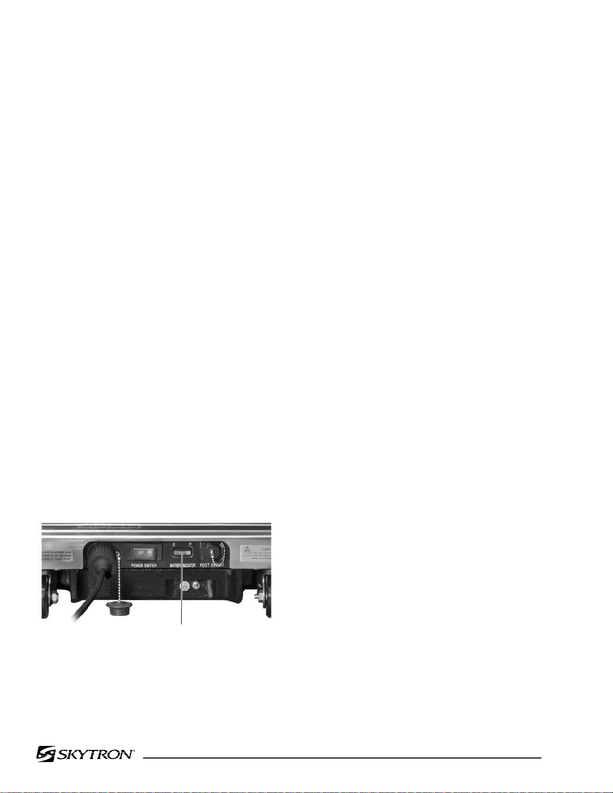
The battery charging indicator and foot control
connector are also located on the electrical panel.
1-2. Power Requirements
The 3600B UltraSlide Surgical Table requires a
120VAC, 60 Hz electrical power supply. The table
is equipped with a removable 15 foot long power
cord with a three prong, hospital grade plug. The
POWER
CORD
MAIN POWER
SWITCH
BATTERY
INDICATOR
Figure 1-2. Electrical Panel
FOOT CONTROL
CONNECTOR

1-3. Pendant Control Unit
AC120V POWER ON
INDICATOR LIGHT
(GREEN)
TABLE UP
(BRAKE LOCK)
LATERAL
TILT LEFT
BACK UP
LEG UP
SLIDE HEAD
FLEX
KIDNEY
LIFT UP
RETURN
TO LEVEL
BATTERY
LATERAL
TILT RIGHT
BACK DOWN
TABLE DOWN
LEG DOWN
SLIDE FOOT
REFLEX
KIDNEY
LIFT DOWN
BEACH
CHAIR
BRAKE
UNLOCK
REVERSE
TRENDELENBURG
TRENDELENBURG
Page 11
The hand-held pendant control unit (figure 1-3)
has a non-slip rubber cover which assures a positive grip during use. A spring clip hanger is located
on the back of the control for storage. When the
Pendant Control is not in use, it should be stored on
a convenient side or end rail. A bracket is located
under the table top next to the pendant control
connector for storage of the Pendant Control when
the table is not in use and during cleaning. See
figure 1-4.
POWER
SIDE RAIL
CLIP
INDICATOR
FUNCTION
BUTTONS
The function push buttons are identified with abbreviated descriptions for all functions. See figure
1-5. When illuminated the Trendelenburg and
table up buttons are red, the remaining buttons are
all green.
PENDANT CONTROL
STORAGE BRACKET
Figure 1-3. Pendant Control Unit
BACK
SECTION
Figure 1-4. Pendant Control Storage Bracket
SEAT
SECTION
Figure 1-5. Function Buttons
1-4. Floor Lock/Brake System
The floor lock/brake system consists of four selfleveling, hydraulic brake cylinders which raise and
support the table base off from the casters. Press
the TABLE UP button on the pendant control to set
the table’s brakes. An electronic timer will activate
the brake system until the brakes are completely
set, approximately 8-10 seconds.
NOTE
Activating any function button will activate the brake system. Using the TABLE
UP function to set the brakes provides
a visual assurance that the brakes are
locked without altering the table position, except when emergency brake is
released.

Page 12
SECTION II OPERATION
2-1. Electrical Power
The 3600B table will operate on either 120 VAC or
battery power.
WARNING
Prior to operating the table, observe
all table caution labels and review the
SPECIAL USER ATTENTION section
in the front of this manual.
WARNING
Possible explosion hazard exists if table
is used in the presence of FLAMMABLE
ANESTHETICS.
POWER
CORD
MAIN POWER
SWITCH
BATTERY
INDICATOR
TWIST TO
LOCK
FOOT CONTROL
EQUALIZATION
GROUNDING TERMINAL
Figure 2-1. Electrical Panel
CONNECTOR
NOTE
An equalization terminal is located under the main power panel. This is provided as an alternate pathway to reduce the risk of static shock hazards.
Always follow recommended grounding procedures to ensure patient and
staff safety.
2-2. AC 120V Operation
Use the following procedures to operate the table
on 120 VAC power.
a. Make sure the Power cord is securely attached to the table. To install the power cord, align
the cord connector with the base connector, insert
the cord and twist clockwise to lock the cord into the
connector. See figure 2-1. Plug the cord into a
properly grounded, Hospital Grade, 120 VAC outlet. Make sure the power cord is routed to the outlet
to prevent it from being in the way of operating
personnel.
The pendant control buttons and the green AC
120V, POWER indicator light located in the upper
right corner of the pendant control will illuminate.
See figure 2-2.
AC120V POWER ON
INDICATOR LIGHT
(GREEN)
Figure 2-2. Pendant Control
b. Activate the POWER SWITCH located on the
electrical panel. The switch will illuminate.
c. The table is now ready for 120VAC operation.

Page 13
2-3. Battery Operation
a. Make sure the Main Power Switch indicator
light, on the electrical panel, are OFF. See figure
2-2. If the indicator light is ON, turn AC120V
operation OFF with the main power switch.
NOTE
The table will operate correctly on battery power with the power cord connected to a wall outlet or disconnected.
b. Press the BATT button on the hand-held
pendant control. The pendant control buttons, the
red BATTERY indicator light, located in the upper
right corner of the pendant control and the Battery
Indicator on the electrical panel will illuminate.
2-4. Automatic Shut-Off
a. To prevent unnecessary discharge of the
battery, a timer is built into the battery circuit. This
timer will automatically shut the battery power OFF
after 1½ hours of table inactivity.
b. To turn the table ON again, press the BATT
button on the pendant control, the pendant control
buttons and the red indicator light will illuminate.
NOTE
Turning the Main Power Switch ON will
change the table operation to 120 VAC
power.
c. The table is now ready for BATTERY opera-
tion.
d. To extend the battery charge life, turn the
BATTERY power OFF with the pendant control
when the table is not going to be used.
NOTE
Battery Operation must be turned OFF
at the pendant control. It cannot be
turned OFF using the main power
switch.
Page 14
2-5. Charging the Battery
Batteries should be charged:
• When the table is placed into initial
service
• As indicated by Battery Indicator
• Every week under normal service
conditions
a. Battery Indicator The Battery Indicator
consists of ten lighted bars, 3 red, 4 yellow and 3
green. See figure 2-3. Each bar represents a
percentage of the battery charge condition. When
all ten bars are illuminated, the batteries are fully
charged. The following list shows the battery
charge level as indicated by the lighted bars;
3 green 100% -Fully charged
2 green 89%
1 green 78%
4 yellow 67%
3 yellow 56%
2 yellow 45% -Needs Charging (BATT
indicator on pendant will flash)
1 yellow 34% -Needs Charging
3 red 23% -Needs Charging
(poor performance)
2 red 12% -Needs Charging
(intermittent performance)
1 red 1% -Needs Charging
(inoperable)
During charging, the bars will light in sequence to
the respective charge level, turn off and light in
sequence again.
NOTE
When the red light starts to blink (indicating low power in battery) the table
will operate for approximately 5 continuous minutes, typically long enough
to use the table for the rest of the day.
NOTE
The charging system operates ONLY
when the table is in AC120V operation
mode.
c. To recharge the battery, make sure the power
cord is connected, plugged into a 120VAC wall
outlet and the main POWER SWITCH - ON.
NOTE
The table can be operated on 120VAC
power while the battery is being recharged.
d. A full battery charge will last approximately 2
weeks under normal operating conditions. However, it is recommended to charge the batteries at
the end of each week to establish a normal routine
protocol. Lead acid batteries last longer if they are
not permitted to fully discharge. The table features
(2) 12 volt, sealed, lead acid batteries which require no manual maintenance. Lead acid gel batteries, under a proper charging program, feature
an approximate normal life of 4 years.
BATTERY
INDICATOR
Figure 2-3. Battery Indicator
b. If the battery needs to be charged when
operating the table on battery power, the red indicator light on the pendant control will begin to blink.
NOTE
If the table is stored for a period greater
than 6 months, the batteries should be
removed and stored in a dry, clean condition at a storage temperature of 68° F
(20° C). Batteries should be recharged
every 6 months of product storage.

2-6. Positioning Functions
Page 15
The hand-held pendant control (figure 2-4) activates the following table functions:
TRENDELENBURG
REVERSE
LATERAL
TILT LEFT
BACK UP
TABLE UP
(BRAKE LOCK)
SLIDE HEAD
LEG UP
FLEX
KIDNEY
LIFT UP
RETURN
TO LEVEL
BATTERY
AC120V POWER ON
INDICATOR LIGHT
(GREEN)
TRENDELENBURG
LATERAL
TILT RIGHT
BACK DOWN
TABLE DOWN
SLIDE FOOT
LEG DOWN
REFLEX
KIDNEY
LIFT DOWN
BEACH
CHAIR
BRAKE
UNLOCK
Figure 2-4. Pendant Control Function Buttons
a. Floor Lock/Brake System. To activate the
brakes without affecting table positioning, press
the TABLE UP button. See figure 2-5. The
elevation cylinder will not function until the brakes
are completely extended.
Press the BRAKE UNLOCK button on the pendant
control to release the four self-leveling brake feet in
order to move the table. See figure 2-5. The brake
delay circuit automatically retracts the brake system. It takes approximately 7-8 seconds to totally
release the system.
WARNING
•DO NOT unlock brakes when a patient
is on the table. An uneven patient
weight load may cause instability.
•If circumstances demand table brakes
to be unlocked, the patient must be
centered and evenly distributed on the
table top (i.e. supine or prone position)
with the table lowered to its lowest
height position. The maximum patient
weight should not exceed 500 pounds.
Table top slide must be centered (indicated by a green LED light on the
pendant control) prior to unlocking
brakes. Patient's head must be on the
head section. Head section must be
attached in its normal orientation to the
table's back section.
•Prior to unlocking brakes, check for
obstructions on the floor that might
prevent the table from moving smoothly
to new location. Relock the brakes immediately once the final position is
reached and before commencing surgery. Table brakes should remain locked
at all times if patient weight exceeds
500 pounds.
TABLE UP
(BRAKE LOCK)
BRAKE
UNLOCK
Figure 2-5. Brake System Activation
NOTE
With an evenly distributed patient weight
load, all table positioning functions will
operate smoothly and quietly with a
patient weight of up to 800 pounds.

Page 16
b. Trendelenburg. To place the table in a
Trendelenburg (head down) position, press the
TREND button (figure 2-6). To place the table in a
reverse Trendelenburg (head up) position, press
the REV TREND button. Trendelenburg positioning of up to 30° may be obtained.
WARNING
To maximize patient safety, utilize
proper restraint methods during extreme
Trendelenburg positioning.
WARNING
To maximize patient safety, utilize
proper restraint methods during extreme
lateral tilt positioning.
LATERAL
TILT LEFT
LATERAL
TILT RIGHT
TRENDELENBURG
REVERSE
30˚
30˚
TRENDELENBURG
Figure 2-6. Trendelenburg Positioning
c. Lateral Tilt. To achieve lateral tilt right (as
viewed from the head end of the table), press the
TILT RIGHT button (figure 2-7). To achieve lateral tilt
left, press the TILT LEFT button. Tilt of up to 30° may
be obtained.
30˚ 30˚
Figure 2-7. Lateral Tilt Positioning
d. Back Section. To raise the back section,
press the BACK UP button (figure 2-8). The back
section will raise up to 90° above horizontal. To
lower the back section, press the BACK DOWN
button. The back section will go down to 40° below
horizontal.
NOTE
If the table top is slid toward the foot
end, the back section will not go below
horizontal. An audible alarm will sound.
NOTE
To prevent damage to the kidney lift, a
safety interlock prevents the back section from going more than 45° above
horizontal if the kidney lift is not all the
way down. An audible alarm will sound.

BACK UP
9-1/2"
SLIDE HEAD
SLIDE FOOT
13-1/2"
90˚
40˚
BACK DOWN
Figure 2-8. Back Section Positioning
Page 17
f. Top Slide. To move the table top toward the
head end, press the SLIDE HEAD button. From
center position, the top will slide up to 9-1/2". See
figure 2-10.
NOTE
If the leg section is positioned more
than 45° below horizontal, the top will
not slide toward the head end. An
audible alarm will sound.
NOTE
If the leg section is below horizontal,
slide toward head is limited to 7-1/2"
e. Elevation. To raise table top, press the
TABLE UP button (figure 2-9). The table will lift a
patient weight of 1,000 pounds up to a maximum
height of 42-1/2" (46-1/2" with X-Ray top and 2"
pad). To lower the table top, press the TABLE
DOWN button. The table top will go down to a
minimum height of 24" (minus pad).
TABLE
UP
42-1/2"
24"
TABLE
DOWN
To move the table top toward the foot end, press
the SLIDE FOOT button. From center position, the
top will slide up to 13-1/2". Slide function will stop
and RETURN CTR Indicator will illuminate when
table is centered.
NOTE
If the back section is positioned below
horizontal, the top will not slide toward
the foot end. An audible alarm will
sound.
Figure 2-9. Elevation Function
Figure 2-10. Top Slide

Page 18
g. Leg Section. To lower the leg section, press
the LEG DOWN button (figure 2-11). The leg
section will go down to 100° below horizontal. To
raise the leg section, press the LEG UP button.
The leg section will go up to 15° above horizontal.
CAUTION
The Leg section may hit the table base
or the floor if both the leg and elevation
systems are placed in their full down
position.
NOTE
If the top is slid toward the head end
less than 7-1/2", the leg section will only
go down 45°. An audible alarm will
sound.
If the top is slid toward the head end
more than 7-1/2", the leg section will
not go below horizontal.
h. Flex Positioning. To place the table top in
a flex position from horizontal, press the FLEX
button (figure 2-12). To return the table top to a
horizontal position or into a reflex position, press
the LEVEL or REFLEX button.
NOTE
If the top is slid toward the foot end, the
FLEX function will not operate. An
audible alarm will sound.
FLEX
REFLEX
LEG UP
LEG DOWN
15˚
100˚
Figure 2-11. Leg Section Positioning
Figure 2-12. Flex/Reflex Positioning

i. Kidney Lift. To raise the built-in kidney lift,
press the KIDNEY UP button (figure 2-13). Up to
5-3/4" of lift can be achieved. Press the KIDNEY
DOWN button to lower the kidney lift.
NOTE
To prevent damage to the kidney lift, a
safety interlock prevents the kidney lift
from going up if the back section is 45°
above horizontal. An audible alarm will
sound .
KIDNEY UP
5-3/4"
KIDNEY DOWN
Page 19
RETURN
TO LEVEL
Figure 2-14. Return To Level
k. Beach Chair. To place the top in the beach
chair position from a level position, press the
BEACH CHAIR button (figure 2-15). The back
section will raise, the leg section will lower and the
Trendelenburg positioning will function simultaneously. The functions will stop when Trendelenburg reaches it limit.
Figure 2-13. Kidney Lift Positioning
j. Return To Level. To return the table top to a
level position, press the LEVEL button (figure 2-14).
NOTE
Elevation and brake system functions
are not affected by the return to level
function.
NOTE
The table top must be centered or slid
toward the foot end for the Beach Chair
function to operate.
BEACH
CHAIR
Figure 2-15. Beach Chair Positioning

Page 20
2-7. Emergency Back-up Controls
a. The emergency back-up control switches are
located under the access door on the service
access cover in the table base. See figure 2-16.
REV
TREND
TILT
BACKUPTABLEUPLEGUPBRAKE
RIGHT
LOCK
FUNCTION CONTROL
ACCESS DOOR
Figure 2-16. Emergency Controls Location
b. In the event of either a power failure or a
problem with the hand-held pendant control, the
table can be operated using the emergency backup switches. Simply push the desired emergency
switch in the appropriate direction to operate the
table functions. See figure 2-17.
TREND TILT
LEFT
BACK
DOWN
TABLE
DOWN
LEG
DOWN
KIDNEY
DOWN
Figure 2-17. Emergency Back-Up Controls
CAUTION
The EMERGENCY BRAKE LOCK
switch does not activate the brake system timer. The switch must be held
until the brakes are completely locked,
approximately 10 seconds.
NOTE
The emergency back-up control
switches will function when the table is
operating on 120VAC power, battery
power, or turned off.
CAUTION
The safety interlock system is not operational when the emergency backup control switches are used.
c. Switches are provided for Trendelenburg,
lateral tilt, back section, elevation, leg section,
kidney down and brake lock. These switches are
spring-loaded so they return to the neutral or
center position when released.

2-8. Emergency Brake Release.
SERVICE ACCESS
COVER
POWER
CORD
EMERGENCY
BRAKE RELEASE
BRAKE (4)
In case of a power failure or an electrical problem
within the table, the emergency brake release
system can be used to move the table. The control
knob for this function is located on the side of the
table base and is identified by an EMERGENCY
BRAKE RELEASE label. Turn the knob counterclockwise to release the brakes. See figure 2-18.
WARNING
•DO NOT unlock brakes when a patient
is on the table. An uneven patient
weight load may cause instability.
•If circumstances demand table brakes
to be unlocked, the patient must be
centered and evenly distributed on the
table top (i.e. supine or prone position)
with the table lowered to its lowest
height position. The maximum patient
weight should not exceed 500 pounds.
Table top slide must be centered (indicated by a green LED light on the
pendant control) prior to unlocking
brakes. Patient's head must be on the
head section. Head section must be
attached in its normal orientation to the
table's back section.
•Prior to unlocking brakes, check for
obstructions on the floor that might
prevent the table from moving smoothly
to new location. Relock the brakes immediately once the final position is
reached and before commencing surgery. Table brakes should remain locked
at all times if patient weight exceeds
500 pounds.
Page 21
Figure 2-18. Emergency Brake Release
NOTE
The Emergency Brake Release Valve
must be closed and tightened (clockwise) before activating any function.
•If the Emergency Brake Release Valve
has been operated, the UNLOCK button
on the pendant control will have to be
pressed before brakes will lock again.

Page 22
2-9. Head Section
a. A quick release positioning bar located under
and to the front of the head section (figure 2-19) is
used to raise or lower the head section. Pull the
release bar toward the head end to allow the
section to pivot up or down. Positioning from 60°
above horizontal to 90° below horizontal in 15°
increments is available. Release the bar to lock the
head section in position.
HEAD SECTION
RELEASE BAR
Figure 2-19. Head Section Adjustment
b. By loosening two locking knobs beneath the
back section, an additional 2" of longitudinal adjustment can be achieved. If desired, the head
section may be removed by loosening the locking
knobs and pulling it straight out of the back section.
3600B UltraSlide Table has the capability of attaching the head section to the leg section
for use
as a foot extension ONLY. Do Not reverse the
patient on the table without first consulting with
SKYTRON.
FOOT/LEG
SECTION
LOCKING
KNOB
HEAD
SECTION
LOCKING
KNOB
Figure 2-20. Repositioning Head Section
(for use as a Foot Extension)
2-10. Leg and Back Section Removal.
a. The Leg Section and the Back Section on the
3600B UltraSlide table are both removable. See
figure 2-21 (Leg Section shown).
b. To remove either section, level the table top,
simultaneously depress both release levers and
pull the section out. Press the LEG DOWN or
BACK DOWN button on the pendant control to
position the attachment pins down and out of the
way.
NOTE
To make the Back Section easier to
handle, remove the Head Section, pad
and X-ray top prior to removing the
Back Section. Remove the pad and Xray top prior to removing the Leg Section.
Two locking knobs are located on the inside of the
leg section for securing the head section. See
figure 2-20.

Page 23
FOOT/LEG SECTION
LOCKING
LEVERS
Figure 2-21. Leg Section Removal
c. To install the Leg Section, press and hold the
LEG UP button until the attachment pins completely stop. Install the section on the pins. Level
the table top and pull out on the section to make
sure the release levers are completely locked.
d. To install the Back Section if the attachment
pins are not aligned, make sure the table top is
centered or toward the head end, press and hold
the BACK DOWN button until the attachment pins
completely stop (40° down). Press REV TREND to
bring the pins up to a level position and install the
section on the pins. Level the table top and pull out
on the section to make sure the release levers are
completely locked.
WARNING
WARNING
Consult manufacturer's instructions
when using high frequency surgical
equipment, cardiac defibrillator and cardiac defibrillator monitors.
WARNING
When an antistatic pathway is required,
the table has to be used on an antistatic
floor.
WARNING
The antistatic properties of the table
are dependent on the use of the original
pad set which was furnished with the
table or an alternate approved replacement.
2-11. Positioning
The use of certain optional accessories available
from SKYTRON further extend the positioning
capabilities of the 3600B UltraSlide Table. Refer to
the following "Positioning Guidelines" or contact
your SKYTRON representative for further details.
Ensure that the Leg and Back sections
are properly engaged and secured to
pins before use to prevent injury.
NOTE
The Leg and Back sections are labeled
for proper orientation. The Leg section
cannot be installed on the Back section
pins.
WARNING
Certain accessories may limit weight
capacities. Check with your SKYTRON
representative.

Page 24
UltraSlide 3600B Bariatric Recommended Patient Positioning
Abdominal Laparoscopic Gastric Bypass
Cysto/GYN
Upper Body Imaging
ENT
UltraSlide 3600B Positioning Guidelines
Lower Body Imaging
Lap Nissen
Urology

Page 25
Ophthalmic/ENT
Neuro (neck) Neuro (lumbar)
Nephrectomy
Shoulder Arthroscopy
Orthopedic (with Traction Accessories)
Lumbar
Endovascular (with optional 48” Carbon
Fiber Leg Extension)

Page 26
SECTION III MAINTENANCE
3-1. Preventive Maintenance
The following preventive maintenance checks and
services are recommended to ensure the serviceability and proper operation of your SKYTRON
Surgical Table, and should only be performed by
qualified SKYTRON trained personnel.
a. During normal cleaning, a general visual
examination should be made checking for leaks,
loose bolts or parts, and cracked, chipped, or
missing paint. Any necessary repairs should be
made.
b. Semi-annually the following checks and services should be performed:
1. Check all hydraulic fittings, mini-valves and
slave cylinders for proper operation and
any signs of leaks.
2. Check the hydraulic speed controls and
adjust if necessary.
3. Pressure check (with a gauge) the pressure relief valve.
4. Check all mechanical adjustments and adjust as necessary.
3-2. Cleaning Recommendations
NOTE
Always follow current AORN Journal
Guidelines to ensure proper cleaning
and disinfection procedure.
The following procedures should be followed when
cleaning the surgical table between cases.
Place table top in level position prior to starting
cleaning procedure.
WARNING
Always follow OSHA blood-borne pathogens standards for protective clothing,
including gloves, masks and eye protection when cleaning the surgical table.
Remove major contaminants from the table with
disposable materials following appropriate biohazard waste disposal procedures.
5. Check hydraulic fluid level.
6. Lubricate the slider assembly.
7. Check function of back and foot leg release
levers, lubricate as necessary.
Remove all table pads and place them on a flat
surface for cleaning.
CAUTION
Thoroughly read and follow the
manufacturer's directions for all cleaning fluids. DO NOT use cleaners containing phenolics.
Apply cleaning fluid liberally to top and sides of
each pad and wipe with a clean lint-free cloth.
Using a clean, damp, lint-free cloth, wipe the pads
to remove the cleaning fluid.

Using a clean, dry, lint-free cloth, wipe the pads to
remove all moisture.
Repeat the steps to clean the bottom of the each
pad.
CAUTION
Page 27
3-3. Service
Table maintenance can be performed by trained
maintenance personnel using SKYTRON authorized replacement parts and service techniques.
Service instructions and parts are available from
SKYTRON.
Preventive Maintenance contracts are available
through your local SKYTRON representative.
When using spray cleaners DO NOT
spray fluids directly into electrical receptacles or micro switches.
Repeat cleaning procedure for all table surfaces
including the top, sides, elevation column, base
and all accessories.
CAUTION
Before replacing pads on the table, make
sure the pads and all mating surfaces
are completely dry. Moisture trapped
between the pads and mating surfaces
may cause distortion of table tops.
When the cleaning procedure is complete, replace
all pads and accessories as applicable.
Remove pendant control from table side rail and
apply cleaning solution to the pendant control and
cord.
To obtain service instructions, replacement parts,
factory service or preventive maintenance contracts, contact the SKYTRON representative listed
below.
Or contact:
SKYTRON
5000 36th Street S.E.
Grand Rapids, MI 49512
1-800-SKYTRON (1-800-759-8766)
Fax. 1-616-957-5053
Use a clean cloth dampened with water to remove
cleaning solution.
Use another clean damp cloth to remove any
remaining residue.
Install pendant control on side rail for storage when
cleaning procedure is complete.

5000 36th Street S.E., Grand Rapids, MI 49512
1-800-SKYTRON or 1-616-957-0500 • FAX 1-616-957-5053

SURGICAL T ABLE
PARTS MANUAL
10/05
3600B UltraSlide

INTRODUCTION
This manual contains the exploded views and replacement parts lists for the service-
able components of the SKYTRON Model 3600B UltraSlide Surgical Table.
Each serviceable part in these exploded views is identified by a reference number.
Use this number to locate necessary par t information in the par ts list adjacent to the exploded view .
Always use the complete SKYTR ON part number and description when ordering
replacement parts.
Always use the complete table serial number (S.N.) when ordering replacement
parts.
Special Tools and Maintenance Items listed on pa ge 46.
Page 1
SERIAL NUMBER TAG
Abbreviations
As Required .......................................... A/R
Optional................................................... opt
Serial Number ....................................... S.N.
Not Shown .............................................. N S
10/05
Although current at the time of publication, SKYTRON's policy of continuous development makes this
manual subject to change without notice.
Page 2
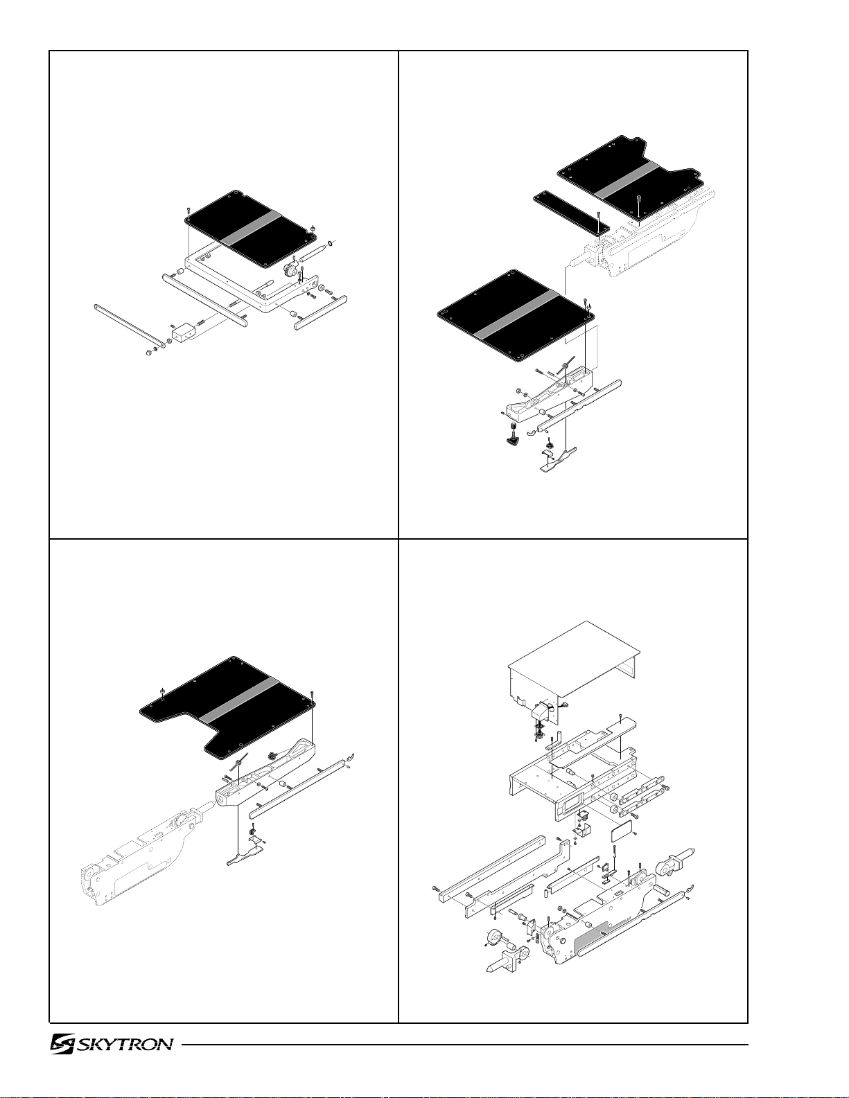
1. Head Section Assembly ......................................Page 6 2. Back Section Assembly...................................... Page 8
3. Leg Section Assembly.......................................Page 10 4. Side Frame and Slide Assemblies ................... Page 12

Page 3
5. Back & Leg Section Cylinder Assemblies.........Page 16 6. Kidney Lift Assembly........................................ Page 18
7. Slide Cylinder Assembly ...................................Page 20 8. Lateral Tilt Assembly ........................................ Page 22

Page 4
9. Trendelenburg Cylinder
& Support Column Assembly ...........................Page 24 10. Support Column Assembly ............................ Page 28
11. Electrical Components .................................... Page 30 12. Hydraulic Valves & Fittings............................. Page 34

Page 5
13. Electro / Mini Valve Assembly .........................Page 38 14. Base Assembly ............................................... Page 40
15. Base Assembly - IR Remote ...........................Page 42

Page 6 1. HEAD SECTION ASSEMBLY
1
2
3
4
31
30
17
27
29
18
28
26
24
25
23
22
17
21
7
9
8
10
11
5
6
12
13
14
16
15
19
18
20
17
3600.0605.01

1. HEAD SECTION ASSEMBLY
Item Part No. Description Qty.
1-010-36-P PAD SET, regular ........................................................................................................opt.
1-010-36-S PA D S E T, soft ..............................................................................................................opt.
1 D3-010-19 SCREW, phillips head ................................................................................................. 4
2 D3-067-01 TOP, head section ........................................................................................................ 1
3 D3-010-18-H VELCRO, hook ............................................................................................................ A/R
4 5-010-01-8 BUSHING, x-ray top ..................................................................................................... 2
5 D4-010-14 O-RING, P-12 ............................................................................................................... 2
6 D3-067-02 SHAFT, extension, head section (roll pin) ................................................................... 2
7 D6-050-33 PIN, roll, M5 x 20 .......................................................................................................... 2
8 D3-032-80 GEAR, trunnion, right ................................................................................................... 1
D3-032-81 GEAR, trunnion, left ..................................................................................................... 1
9 D6-010-41-1 SCREW, set, M8 x 15 (plated) ..................................................................................... 2
10 D6-010-38-1 BOLT, allen, M6 x 15 (plated)....................................................................................... 2
11 D6-010-40-1 WASHER, lock, M6 (plated) ......................................................................................... 2
12 D3-067-03 FRAME, head section .................................................................................................. 1
13 D3-034-22 BUSHING, head section .............................................................................................. 2
14 D6-010-53-1 BOLT, allen, M8 x 20 (plated)....................................................................................... 2
15 D3-032-34 STUD, side rail mount, M8 x 45 ................................................................................... 2
16 D3-067-04 RAIL, side, head section .............................................................................................. 2
17 D3-032-35 STUD, side rail mount, M8 x 40 ................................................................................... 4
18 D3-010-01 COLLAR, side rail ........................................................................................................ 6
19 D6-010-38 BOLT, allen, M6 x 15 .................................................................................................... 4
20 D6-010-40 WASHER, lock, M6....................................................................................................... 4
21 D3-067-05 PLUNGER, release, right............................................................................................. 1
D3-067-06 PLUNGER, release, left ............................................................................................... 1
22 D6-010-13 NUT, hex, M8................................................................................................................ 6
23 D6-010-09 WASHER, lock, M8....................................................................................................... 6
24 D3-032-33 RAIL, accessory ........................................................................................................... 1
25 D3-067-07 SPRING, release .......................................................................................................... 2
26 D3-032-40 BLOCK, bearing ........................................................................................................... 2
27 D6-010-11 SCREW , set, M5 x 8 (plated)........................................................................................ 2
28 D6-010-13-1 NUT, hex, M8 (plated).................................................................................................. 2
29 D3-010-24 RELEASE BAR, head section ..................................................................................... 1
30 D6-010-09 WASHER, lock, M8....................................................................................................... 2
31 D6-010-08 NUT, acorn, M8 ............................................................................................................ 2
Page 7

Page 8
2. BACK SECTION ASSEMBLY
23
22
2
3
3
1
2
3
4
13
12
10
14
11
19
18
15
16
7
9
8
6
24
5
17
20
21
3600.0605.02

2. BACK SECTION ASSEMBLY
Item Part No. Description Qty.
1-010-36-P PAD SET, regular ........................................................................................................opt.
1-010-36-S PA D S E T, soft ..............................................................................................................opt.
1 D3-033-01 TOP, back section......................................................................................................... 1
2 D3-010-18-H VELCRO, hook ............................................................................................................ A/R
3 D3-010-19 SCREW, phillips head ................................................................................................ 22
4 5-010-01-8 BUSHING, x-ray top ..................................................................................................... 8
5 D3-034-12 SIDE RAIL, back section, right ..................................................................................... 1
D3-034-13 SIDE RAIL, back section, left ....................................................................................... 1
6 D3-036-02 FRAME, back section, right.......................................................................................... 1
D3-036-03 FRAME, back section, left ............................................................................................ 1
7 D3-032-51 SPRING, back section, right ........................................................................................ 1
D3-032-51-1 SPRING, back section, left ........................................................................................... 1
8 D6-032-37 PIN, roll, M4 x 30 .......................................................................................................... 2
9 D6-010-65-1 BOLT, allen, M5 x 35 (plated)....................................................................................... 2
10 D6-010-13-1 NUT, M8 (plated).......................................................................................................... 6
11 D6-010-09-1 WASHER, lock, M8 (plated) ......................................................................................... 6
12 D6-067-02 SCREW , set, M5 x 13................................................................................................... 2
13 D3-031-83 KNOB, head section .................................................................................................... 2
14 D3-010-43 STOP, rail (large).......................................................................................................... 2
15 D3-010-01 COLLAR, side rail ........................................................................................................ 6
16 D3-010-41 PIN, rail stop................................................................................................................. 2
17 D6-067-01 SCREW, phillips, button head, M3 x 8......................................................................... 2
18 D3-034-46 STOP, rubber................................................................................................................ 2
19 D3-034-47 HINGE .......................................................................................................................... 2
20 D6-010-79 SCREW, phillips, button head, M3 x 5......................................................................... 4
21 D3-034-14 LEVER, release ........................................................................................................... 2
22 D3-036-04 TOP, seat section.......................................................................................................... 1
23 D3-036-05 TOP, seat section (small).............................................................................................. 1
24 D3-032-34 STUD, side rail mount, M8 x 45 ................................................................................... 6
Page 9
Page 10
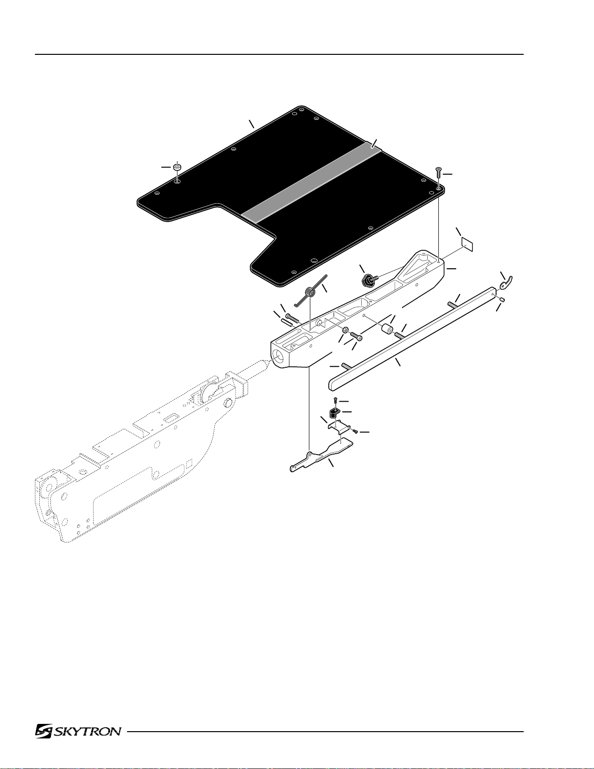
3. LEG SECTION ASSEMBLY
2
3
1
4
23
6
5
13
15
8
9
7
12
15
14
10
11
16
22
17
19
18
20
21
3600.0605.10

3. LEG SECTION ASSEMBLY
Item Part No. Description Qty.
1-010-36-P PAD SET, regular ........................................................................................................opt.
1-010-36-S PA D S E T, soft ..............................................................................................................opt.
1 5-010-01-8 BUSHING, x-ray top ..................................................................................................... 2
2 D3-067-17 TOP, leg section .......................................................................................................... 1
3 D3-010-18-H VELCRO, hook ............................................................................................................ A/R
4 D3-010-19 SCREW, phillips head ................................................................................................. 8
5 D6-067-18 FRAME, leg section, right (shown) .............................................................................. 1
D6-067-19 FRAME, leg section, left............................................................................................... 1
6 D6-031-01 KNOB, retaining, leg section........................................................................................ 2
7 D3-034-18 SPRING, leg section, right (shown) ............................................................................. 1
D3-034-19 SPRING, leg section, left.............................................................................................. 1
8 D6-010-65-1 BOLT, allen, M5 x 35 (plated)....................................................................................... 2
9 D6-034-02 PIN, roll, M4 x 30 .......................................................................................................... 4
10 D6-010-76 NUT, hex, M5................................................................................................................ 2
11 D6-010-83 BOLT, allen, M5 x 30 .................................................................................................... 4
12 D3-010-01 COLLAR, side rail ........................................................................................................ 6
13 D3-010-43 STOP, rail, large ........................................................................................................... 2
14 D3-010-41 PIN, rail stop................................................................................................................. 2
15 D3-032-34 STUD, side rail mount, M8 x 45 ................................................................................... 4
16 D3-032-35 STUD, side rail mount, M8 x 40 ................................................................................... 2
17 D6-067-01 SCREW, phillips, button head, M3 x 8......................................................................... 2
18 D3-034-46 STOP, rubber................................................................................................................ 2
19 D3-034-47 HINGE .......................................................................................................................... 2
20 D6-010-79 SCREW, phillips, button head, M3 x 5......................................................................... 4
21 D3-034-14 LEVER, release ........................................................................................................... 2
22 D3-032-15 RAIL, side, leg section, right (shown) .......................................................................... 1
D3-032-16 RAIL, side, leg section, left........................................................................................... 1
23 D6-011-31 LABEL, 140 lbs., cautionary ........................................................................................ 1
Page 11

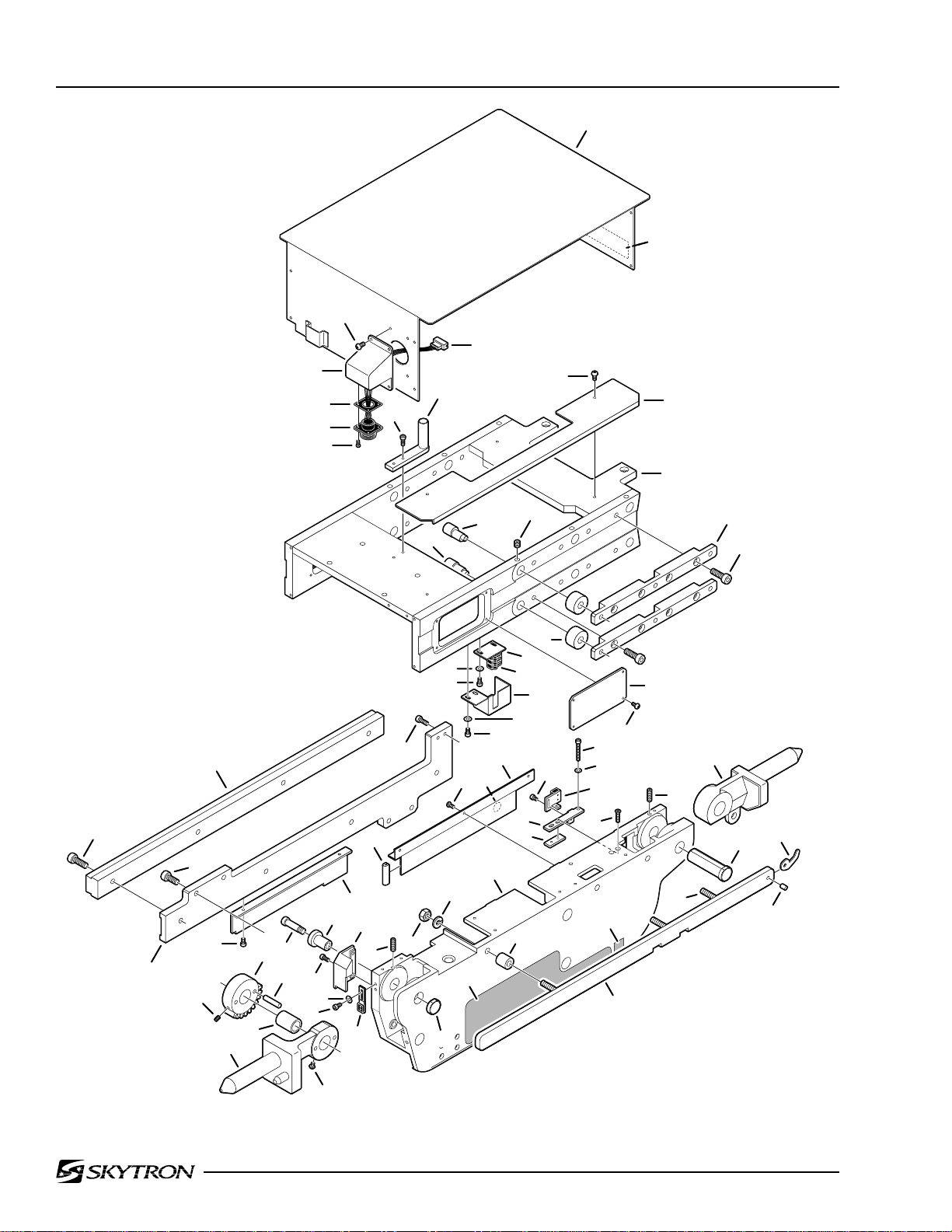
Page 12 4. SIDE FRAME AND SLIDE ASSEMBLIES
3
5
4
10
6
9
7
8
11
1
2
12
13
16
28
27
38
26
30
35
41
39
49
40
46
42
43
48
34
29
47
70
44,45
69
50
15B
37
25
24
51
31
53
15A
24
33
32
52
54
22
25
57
56
14
21
18
23
62
59
58
60,61
63
66
55
19
20
70
71
64
17
16
65
68
67
36
3600.0605.03

4. SIDE FRAME AND SLIDE ASSEMBLIES
Item Part No. Description Qty.
1 D3-036-06 COVER, hose ............................................................................................................... 1
2 ----- TAG, serial number / table info.....................................................................................1
3 D6-036-01 SCREW, roundhead phillips, M4 x 8 .......................................................................... 12
4 D3-036-07 HOUSING, pendant connector .................................................................................... 1
5 D5-036-09 CONNECTOR, 7-pin, female ....................................................................................... 1
D5-036-03 CONNECTOR, 7-pin, male .......................................................................................... 1
6 D5-034-05 GASKET, connector ..................................................................................................... 1
7 D5-034-06 CONNECTOR, 7-pin, female ....................................................................................... 1
8 D6-010-44 SCREW, phillips, M3 x 12 ........................................................................................... 12
9 D6-010-67 BOLT, allen, M5 x 15 .................................................................................................... 2
10 D3-036-08 GUIDE, hose ................................................................................................................ 1
11 D6-036-02 SCREW, roundhead, phillips, M4 x 10 ........................................................................ 4
12 D3-036-09 COVER, hose ............................................................................................................... 2
13 D3-036-10 FRAME, lateral tilt ........................................................................................................ 1
14 D6-010-68 SCREW , set, M8 x 8 .................................................................................................... 12
15A D2-035-07 AXIS, slide roller, eccentric cam .................................................................................. 6
15B D2-035-09 AXIS, slide roller .......................................................................................................... 6
16 D6-010-33 BOLT, allen, M8 x 25 ...................................................................................................A/R
17 D2-035-10 RETAINER, slide roller................................................................................................. 4
18 D2-035-08 ROLLER, slide ............................................................................................................ 12
19 D6-036-01 SCREW, roundhead, phillips, M4 x 8 .......................................................................... 8
20 D3-036-11 COVER, access............................................................................................................ 2
21 D5-036-04 BRACKET, micro-switch mounting .............................................................................. 1
22 D5-036-05 MICRO-SWITCH .......................................................................................................... 3
23 D3-036-12 COVER, micro-switch ................................................................................................... 1
24 D6-060-07 BOLT, allen, M4 x 8 .....................................................................................................A/R
25 D6-035-19 WASHER, flat, M4 .......................................................................................................A/R
26 D3-035-19 BAR, slide .................................................................................................................... 2
27 D6-010-53 BOLT, allen, M8 x 20 ................................................................................................... 16
28 D3-036-13 BRACKET, slide bar, right ............................................................................................ 1
D3-036-14 BRACKET, slide bar, left .............................................................................................. 1
29 D5-036-06 ACTUATOR, slide micro-switch ................................................................................... 1
30 D6-060-07 BOLT, allen, M4 x 8 ...................................................................................................... 2
31 D6-035-04 SCREW, phillips, M4 x 8 .............................................................................................. 6
32 D6-036-03 DECAL, “ground” ......................................................................................................... 2
33 D3-036-15 GUARD, side frame, right............................................................................................. 1
D3-036-16 GUARD, side frame, left ............................................................................................... 1
34 D3-036-17 BUMPER ...................................................................................................................... 2
35 D3-067-12 LEVER, axis, back / seat section, right ........................................................................ 1
D3-067-13 LEVER, axis, back / seat section, left........................................................................... 1
36 D6-067-26 SCREW ........................................................................................................................ 2
37 D3-032-36 CAP, back section axis ................................................................................................. 2
38 D6-010-10-1 SCREW, set, M6 x 10 ................................................................................................... 2
39 D3-036-18 GEAR, spur, back section ............................................................................................ 2
40 D6-034-01 PIN, spur gear, tapered, M7 x 35 ................................................................................. 4
41 D3-032-31 BUSHING, back section............................................................................................... 2
42 D6-060-07 BOLT, allen, M4 x 8 ...................................................................................................... 4
43 D6-035-19 WASHER, flat, M4 ........................................................................................................ 4
44 D5-036-07 MICRO-SWITCH .......................................................................................................... 2
45 D5-036-08 BRACKET, micro-switch mounting .............................................................................. 2
46 D6-010-10-3 BOLT, allen, M4 x 10 .................................................................................................... 4
Page 13
Page 14
4. SIDE FRAME AND SLIDE ASSEMBLIES (continued)
1
2
3
5
4
10
6
9
7
8
11
12
13
16
28
27
38
26
30
35
41
39
49
40
46
42
43
48
34
29
47
70
44,45
69
50
15B
37
25
24
51
31
53
15A
24
33
32
52
54
22
25
57
56
14
21
18
23
62
59
58
60,61
63
66
55
19
20
70
71
64
17
16
65
68
67
36
3600.0605.03

4. SIDE FRAME AND SLIDE ASSEMBLIES (continued)
Item Part No. Description Qty.
47 D3-036-19 COVER, micro-switch, right .......................................................................................... 1
D3-036-20 COVER, micro-switch, left ............................................................................................ 1
48 D3-032-37 AXIS, back section ....................................................................................................... 2
49 D6-032-28 BOLT, allen ................................................................................................................... 2
50 D6-010-13-1 NUT, M8 (plated).......................................................................................................... 6
51 D6-010-09-1 WASHER, lock, M8 (plated) ......................................................................................... 6
52 D3-036-21 FRAME, side, right ....................................................................................................... 1
D3-036-22 FRAME, side, left.......................................................................................................... 1
53 D3-036-23 NAMEPLATE, decal, 3600B, right ............................................................................... 1
D3-036-24 NAMEPLATE, decal, 3600B, left .................................................................................. 1
54 D3-010-01 COLLAR, side rail ........................................................................................................ 6
55 D3-036-25 SIDE RAIL, back section, right ..................................................................................... 1
D3-036-26 SIDE RAIL, back section, left ....................................................................................... 1
56 D5-036-15 BACK PLATE, micro-switch mounting bracket ............................................................ 2
57 D5-036-10 BRACKET, micro-switch mounting, r ight ..................................................................... 1
D5-036-11 BRACKET, micro-switch mounting, left........................................................................ 1
58 D6-034-07 WASHER, flat, M3 .......................................................................................................A/R
59 D6-067-06 BOLT, allen, M3 x 26 ...................................................................................................A/R
60 D5-036-12 MICRO-SWITCH, right ................................................................................................. 1
D5-036-13 MICRO-SWITCH, left.................................................................................................... 2
61 D5-036-14 BRACKET, micro-switch mounting, r ight ..................................................................... 1
D5-036-16 BRACKET, micro-switch mounting, left (short) ............................................................ 1
D5-036-17 BRACKET, micro-switch mounting, left (long) ............................................................. 1
62 D6-036-04 BOLT, allen, M3 x 5 .....................................................................................................A/R
63 D6-066-18 SCREW, countersunk phillips, M4 x 15 ....................................................................... 4
64 D3-034-31 LEVER, axis, foot / leg section, right ............................................................................ 1
D3-034-32 LEVER, axis, foot / leg section, left .............................................................................. 1
65 D3-030-05 AXIS, foot / leg section ................................................................................................. 2
66 D6-067-24 DECAL, equipment type 8 ........................................................................................... 2
67 D3-010-41 PIN, rail stop................................................................................................................. 2
68 D3-010-43 STOP, rail (large).......................................................................................................... 2
69 D6-010-67 BOLT, allen, M5 x 15 .................................................................................................... 4
70 D6-010-87 SCREW , set, M6 x 20................................................................................................... 4
71 D3-032-34 STUD, side rail mount, M8 x 45 ................................................................................... 6
Page 15

Page 16 5. BACK & LEG SECTION CYLINDER ASSEMBLIES
12
4
2
3
2
10
13
1
9
11
12
13
17
7
16
15
14
2
6
8
5
27
19
28
21
22
20
29
13
12
31
23
12
32
30
24
13
37
25
35
9
34
10
38
32
31
30
33
22
22
18
36
18
26
3600.0605.04

5. BACK & LEG SECTION CYLINDER ASSEMBLIES
Item Part No. Description Qty.
D4-036-01 CYLINDER ASSEMBLY, leg section, left...................................................................... 1
D4-036-02 CYLINDER ASSEMBLY, leg section, right (shown) ..................................................... 1
1 ------ •TAIL CAP (not available separately) .......................................................................... 1
2 D4-010-54 •O-RING, P-34.............................................................................................................. 3
3 ------ •CYLINDER (not available separately) ....................................................................... 1
4 ------ •PISTON / RAM (not available separately) .................................................................. 1
5 D4-036-04 •STUD, cylinder............................................................................................................ 4
6 D4-032-44 •O-RING, P-22A ........................................................................................................... 1
7 ------ •HEAD CAP (not available separately) ....................................................................... 1
8 D6-010-55 •NUT, hex, M8 .............................................................................................................. 4
9 D6-010-53 BOLT, allen, M8 x 20 .................................................................................................... 8
10 D4-036-05 PLATE, cylinder mounting, left ..................................................................................... 2
D4-036-06 PLATE, cylinder mounting, right (shown) .................................................................... 2
11 D6-010-87 SCREW , set, M6 x 20................................................................................................... 2
12 ------ HOSE, flexible (specify function) ................................................................................A/R
13 D4-031-06 FITTING, flexible hose ................................................................................................A/R
14 D6-010-34 SCREW , set, M6 x 6 ..................................................................................................... 2
15 D6-036-06 PIN, clevis .................................................................................................................... 2
16 D6-036-07 CLEVIS......................................................................................................................... 2
17 D6-036-08 CIRCLIP ....................................................................................................................... 2
18 D6-036-09 AXIS, eccentric cam ..................................................................................................... 4
D4-036-07 CYLINDER ASSEMBLY, back section, left ................................................................... 1
D4-036-08 CYLINDER ASSEMBLY, back section, right (shown) .................................................. 1
19 D6-010-55 •NUT, hex, M8 .............................................................................................................. 4
20 ------ •HEAD CAP (not available separately) ....................................................................... 1
21 D4-032-44 •O-RING, P-22A ........................................................................................................... 1
22 D4-040-40 •O-RING, P-39.............................................................................................................. 3
23 ------ •CYLINDER (not available separately) ....................................................................... 1
24 D4-036-10 •STUD, cylinder............................................................................................................ 4
25 ------ •PISTON / RAM (not available separately) .................................................................. 1
26 ------ •T AIL CAP (not available separately) .......................................................................... 1
27 D5-036-18 MICRO-SWITCH .......................................................................................................... 2
28 D5-036-19 BRACKET, micro-switch mounting, r ight (shown) ....................................................... 1
D5-036-20 BRACKET, micro-switch mounting, left........................................................................ 1
29 D6-010-10-3 BOLT, allen, M4 x 10 .................................................................................................... 4
30 ------ OIL LINE (specify function) .........................................................................................A/R
31 D4-010-08 O-RING, P-7 ................................................................................................................A/R
32 D4-010-24 BOLT, plumbling M6 .................................................................................................... A/R
33 D3-035-30 AXIS, eccentric cam ..................................................................................................... 2
34 D3-035-29 ROLLER, support ......................................................................................................... 2
35 D3-035-28 SPACER, nylon ............................................................................................................ 2
36 D6-010-91 SCREW , set, M6 x 25................................................................................................... 2
37 D6-036-10 BOLT, allen, M6 x 40 .................................................................................................... 2
38 D4-036-11 BLOCK, plumbing, right (shown) ................................................................................. 1
D4-036-12 BLOCK, plumbing, left ................................................................................................. 1
Page 17

Page 18 6. KIDNEY LIFT ASSEMBLY
13
2
3
3
14
28
26
13
12
11
6
7
8
10
5
3
9
7
4
3
2
1
22
24
23
25
21
20
14
15
17
16
18
19
15
35
1
30
27
29
16
36
17
34
33
32
31
3600.0605.05

6. KIDNEY LIFT ASSEMBLY
Item Part No. Description Qty.
D4-036-13 CYLINDER ASSEMBLY, kidney lift, left ........................................................................ 1
D4-036-14 CYLINDER ASSEMBLY, kidney lift, right (shown) ....................................................... 1
1 D6-036-05 •BOLT, allen, M6 x 94................................................................................................... 8
2 ------ •END CAP, right (not availab le separately) ................................................................. 2
------ •END CAP, left (not available separately).................................................................... 2
3 D4-010-57 •O-RING, P-21.............................................................................................................. 4
4 ------ •CYLINDER (not available separately) ....................................................................... 1
5 ------ •PISTON (not available separately) ............................................................................. 1
6 D6-010-75 •SCREW, set, M5 x 5.................................................................................................... 2
7 D4-036-15 •PILLOW BLOCK.......................................................................................................... 2
8 D4-036-16 •SHAFT......................................................................................................................... 1
9 D4-036-17 •GEAR .......................................................................................................................... 1
10 D6-010-70 •BOLT, allen, M5 x 10................................................................................................... 4
11 D4-036-18 GEAR ........................................................................................................................... 2
12 D4-036-19 SHAFT.......................................................................................................................... 2
13 D4-010-24 BOLT, plumbing, M6 ....................................................................................................A/R
14 D4-010-08 O-RING, P-7 ................................................................................................................A/R
15 ------ OIL LINE (specify function) .........................................................................................A/R
16 D4-010-29 FITTING, hydraulic, 90° elbow ....................................................................................A/R
17 ------ HOSE, flexible (specify function) ................................................................................A/R
18 D6-060-07 BOLT, allen, M4 x 8 ...................................................................................................... 2
19 D5-036-21 COVER, micro-switch................................................................................................... 1
20 D6-060-07 BOLT, allen, M4 x 8 ...................................................................................................... 2
21 D6-035-19 WASHER, flat, M4 ........................................................................................................ 2
22 D5-036-22 MICRO-SWITCH .......................................................................................................... 1
23 D5-036-23 BRACKET, micro-switch mounting .............................................................................. 1
24 D6-035-03 SCREW, countersunk phillips, M5 x 15 ....................................................................... 6
25 D6-036-11 COVER, gear, right (shown) ......................................................................................... 1
D6-036-12 COVER, gear, left ......................................................................................................... 1
26 D6-036-13 GEAR ........................................................................................................................... 2
27 D6-036-14 GEAR ........................................................................................................................... 2
28 D6-035-02 SCREW , set, M5 x 25................................................................................................... 4
29 D4-036-20 VALVE, bypass ............................................................................................................. 1
30 D6-010-91 BOLT, allen, M6 x 25 .................................................................................................... 1
31 D6-010-67 BOLT, allen, M5 x 15 .................................................................................................... 8
32 D3-032-52 SHAFT, kidney lift ......................................................................................................... 2
33 D6-031-24 PIN, roll, M5 x 15 .......................................................................................................... 2
34 D3-032-39-1 PIVOT, kidney lift .......................................................................................................... 2
35 D5-035-42 TOP, kidney lift.............................................................................................................. 1
36 D5-035-42-1 SCREW, round head phillips, M5 x 10 ........................................................................ 4
Page 19

Page 20 7. SLIDE CYLINDER ASSEMBLY
1
23
20
19
12
18
16
17
20
24
16
11
20
20
19
18
17
4
19
21
15
16
16
3
11
2
7
16
17
5
6
7
16
18
8
14
22
9
17
8
16
7
6
16
17
16
30
17
21
10
22
5
27
16
17
17
26
25
7
7
4
29
13
28
16
2
17
16
18
3600.0605.06

7. SLIDE CYLINDER ASSEMBLY
Item Part No. Description Qty.
D4-036-21 SLIDE CYLINDER ASSEMBLY.................................................................................... 1
1 D4-036-22 •BRACKET, cylinder mounting (foot section) ............................................................... 1
2 D4-036-23 •SPACER, nylon ........................................................................................................... 2
3 D4-036-24 •END CAP, cylinder ...................................................................................................... 1
4 D4-036-25 •RAM ............................................................................................................................2
5 D4-010-01 •O-RING, P-8 ................................................................................................................ 2
6 D4-036-26 •PISTON ....................................................................................................................... 2
7 D4-036-27 •O-RING, P-24.............................................................................................................. 5
8 D6-010-13 •NUT, hex, M8 .............................................................................................................. 2
9 D4-036-28 •HOUSING, cylinder..................................................................................................... 1
10 D4-036-29 •HOUSING, tube .......................................................................................................... 1
11 D4-036-31 •END CAP, cylinder ...................................................................................................... 2
12 D4-036-30 •BRACKET, cylinder mounting (head section) ............................................................ 1
13 D4-036-32 •END CAP, cylinder ...................................................................................................... 1
14 D4-036-33 •HOUSING, tube .......................................................................................................... 1
15 D6-010-30 BOLT, allen, M6 x 20 .................................................................................................... 2
16 D4-010-08 O-RING, P-7 ................................................................................................................A/R
17 ------ OIL LINE (specify function) .........................................................................................A/R
18 D4-010-24 BOLT, plumbing, M6 ....................................................................................................A/R
19 D6-036-15 SNAP RING.................................................................................................................. 4
20 D6-010-108 BOLT, allen, M5 x 18 .................................................................................................... 4
21 D4-036-34 BLOCK, guide .............................................................................................................. 2
22 D4-036-35 SLIDE ...........................................................................................................................2
23 D6-010-52 BOLT, allen, M6 x 30 .................................................................................................... 1
24 D6-010-38 BOLT, allen, M6 x 15 .................................................................................................... 1
25 ------ HOSE, flexible.............................................................................................................. 2
26 D4-010-31 FITTING, hose .............................................................................................................. 2
27 D4-036-36 BLOCK, hydraulic ........................................................................................................ 1
28 D4-036-37 COVER, hydraulic block .............................................................................................. 1
29 D6-010-83 BOLT, allen, M5 x 30 .................................................................................................... 2
30 D4-010-26 BOLT, plumbing, M6 (long) .......................................................................................... 2
Page 21

Page 22 8. LATERAL TILT ASSEMBLY
1
9
8
4
7
5
6
5
3
2
24
36
26
23
27
22
28
29
35
30
34
33
32
31
21
30
18
20
19
29
28
13
27
17
16
11
15
10
12
14
22
27
26
25
23
24
3600.0605.07

8. LATERAL TILT ASSEMBLY
Item Part No. Description Qty.
1 D6-010-53 BOLT, allen, M8 x 20 .................................................................................................... 2
2 D6-067-23 SCREW, countersunk phillips, M4 x 8 ......................................................................... 2
3 D5-036-24 ACTUATOR PLATE, micro-switch ................................................................................ 1
4 D2-036-01 MOUNT, Trendelenburg pivot housing ........................................................................ 1
5 D6-036-16 WASHER, thrust ........................................................................................................... 2
6 D6-036-17 BEARING, thrust .......................................................................................................... 1
7 D6-036-18 COVER, bear ing .......................................................................................................... 1
8 D6-010-09 WASHER, loc k, M8....................................................................................................... 1
9 D6-010-53 BOLT, allen, M8 x 20 .................................................................................................... 1
10 D6-060-07 BOLT, allen, M4 x 8 ...................................................................................................... 4
11 D5-036-25 BRACKET, micro-switch mounting .............................................................................. 2
12 D5-036-26 MICRO-SWITCH .......................................................................................................... 2
13 D2-036-02 HOUSING, Trendelenburg pivot .................................................................................. 1
14 D2-036-03 AXIS, lateral-tilt pivot .................................................................................................... 1
15 D5-036-27 ACTUATOR PLATE, micro-switch ................................................................................ 1
16 D6-067-23 SCREW, countersunk phillps, M4 x 8 .......................................................................... 4
17 D5-036-28 ACTUATOR PLATE, micro-switch ................................................................................ 1
18 D2-036-04 LEVER, lateral-tilt motion............................................................................................. 1
19 D6-010-54 BOLT, allen, M8 x 30 .................................................................................................... 4
20 D6-035-06 SCREW , set, M6 x 25................................................................................................... 1
21 D2-036-05 PIN, lateral-tilt lever...................................................................................................... 1
22 ------ HOSE, flexible (specify function) ................................................................................A/R
23 D4-010-30 FITTING, hydraulic, 45° elbow ..................................................................................... 2
24 D6-010-33 BOLT, allen, M8 x 25 .................................................................................................... 8
25 D4-036-38 CAP, end, right side...................................................................................................... 1
26 D4-035-23 O-RING, S-50 ............................................................................................................... 2
27 D4-010-04 O-RING, P-44 ............................................................................................................... 4
28 D4-035-25 PISTON ........................................................................................................................ 2
29 D4-036-39 ROD, connecting .......................................................................................................... 2
30 D4-036-40 SLEEVE ....................................................................................................................... 2
31 D6-031-18 BOLT, allen, M8 x 90 .................................................................................................... 4
32 D6-036-19 SCREW , set, M4 x 5 ..................................................................................................... 2
33 D2-035-33 BEARING, sealed roller ............................................................................................... 1
34 D6-036-20 CIRCLIP ....................................................................................................................... 1
35 D4-036-41 HOUSING, lateral tilt cylinder ...................................................................................... 1
36 D4-036-42 CAP, end, left side ........................................................................................................ 1
Page 23

Page 24 9. TRENDELENBURG CYLINDER & SUPPORT COLUMN ASSEMBLY
17
3
53
1
21
23
2
22
36
24
5
25
37
26
4
7
8
10
13
6
27
9
28
29
30
15
11
12
14
16
31
18
57
56
58
55
54
52
51
19
43
20
44
44
50
45
46
48
47
49
42
35
39
41
40
32
33
35
34
38
37
3600.0605.08

9. TRENDELENBURG CYLINDER & SUPPORT COLUMN ASSEMBLY
Item Part No. Description Qty.
1 D2-036-06 AXIS, Trendelenburg pivot ........................................................................................... 2
2 D6-060-07 BOLT, allen, M4 x 8 ...................................................................................................... 2
3 D2-036-07 COVER......................................................................................................................... 1
4 D5-036-29 CONNECTOR, 2-pin, male .......................................................................................... 2
5 D5-036-30 CONNECTOR, 2-pin, female ....................................................................................... 2
6 D6-010-53 BOLT, allen, M8 x 20 .................................................................................................... 3
7 D6-011-20 SCREW, phillips, M3 x 10 ............................................................................................ 8
8 D5-036-31 TERMINAL STRIP........................................................................................................ 2
9 D6-065-08 BOLT, allen, M4 x 12 .................................................................................................... 4
10 D6-035-19 WASHER, flat, M4 ........................................................................................................ 4
11 D5-036-32 BRACKET, micro-switch mounting .............................................................................. 2
12 D5-036-33 MICRO-SWITCH .......................................................................................................... 2
13 D6-036-22 SPACER....................................................................................................................... 4
14 D6-060-07 BOLT, allen, M4 x 8 ...................................................................................................... 2
15 D2-036-08 BRACKET .................................................................................................................... 1
16 D6-010-33 BOLT, allen, M8 x 25 .................................................................................................... 6
17 D2-036-09 CAP, slider, section #1 ................................................................................................. 1
18 D2-036-10 COVER......................................................................................................................... 2
19 D6-050-36 BOLT, allen, M5 x 8 ...................................................................................................... 4
20 D6-010-50 SCREW , set, M6 x 15................................................................................................... 2
D4-036-43 CYLINDER ASSEMBLY, Trendelenburg (includes D4-036-45) .................................. 1
21 D4-036-44 •ROD ............................................................................................................................1
22 ------ •RETAINER NUT, ball joint (not available separately) ................................................ 1
23 D6-010-51 •BOLT, allen, M6 x 10................................................................................................... 4
24 D4-060-23 •O-RING, P-20.............................................................................................................. 1
25 D4-036-46 •CAP, end, top .............................................................................................................. 1
26 D4-035-29 •O-RING, P-65.............................................................................................................. 1
27 D4-010-56 •O-RING, P-10A ........................................................................................................... 1
28 D4-036-47 •PISTON ....................................................................................................................... 1
29 D4-010-06 •O-RING, P-60.............................................................................................................. 1
30 D6-010-43 •NUT, hex, M10 ............................................................................................................ 1
31 D4-036-48 •CYLINDER.................................................................................................................. 1
32 D4-010-10 •O-RING, G-65 ............................................................................................................. 1
33 D4-036-49 •CAP, end, bottom ........................................................................................................ 1
34 D4-036-50 •NUT, bottom end cap .................................................................................................. 1
35 D4-036-51 SHIM ............................................................................................................................2
36 D4-010-29 FITTING, hydraulic, 90° elbow ..................................................................................... 1
37 ------ HOSE, flexible (specify function) ................................................................................A/R
38 D4-010-30 FITTING, hydraulic, 45° elbow ..................................................................................... 1
39 D6-060-38 SCREW , set, M5 x 10................................................................................................... 2
40 D2-036-11 AXIS, Trendelenburg cylinder ...................................................................................... 1
41 D6-010-53 BOLT, allen, M8 x 20 .................................................................................................... 4
42 D2-036-12 MOUNT, Trendelenburg cylinder ................................................................................. 1
43 D2-036-13 GUIDE, left ................................................................................................................... 1
44 D6-010-51 BOLT, allen, M6 x 10 .................................................................................................... 2
45 D2-036-14 GUIDE, right ................................................................................................................. 1
46 D2-036-15 GUIDE, hose ................................................................................................................ 2
47 D6-010-51 BOLT, allen, M6 x 10 .................................................................................................... 2
48 D2-036-16 GUIDE, hose ................................................................................................................ 2
49 D6-010-51 BOLT, allen, M6 x 10 .................................................................................................... 2
Page 25
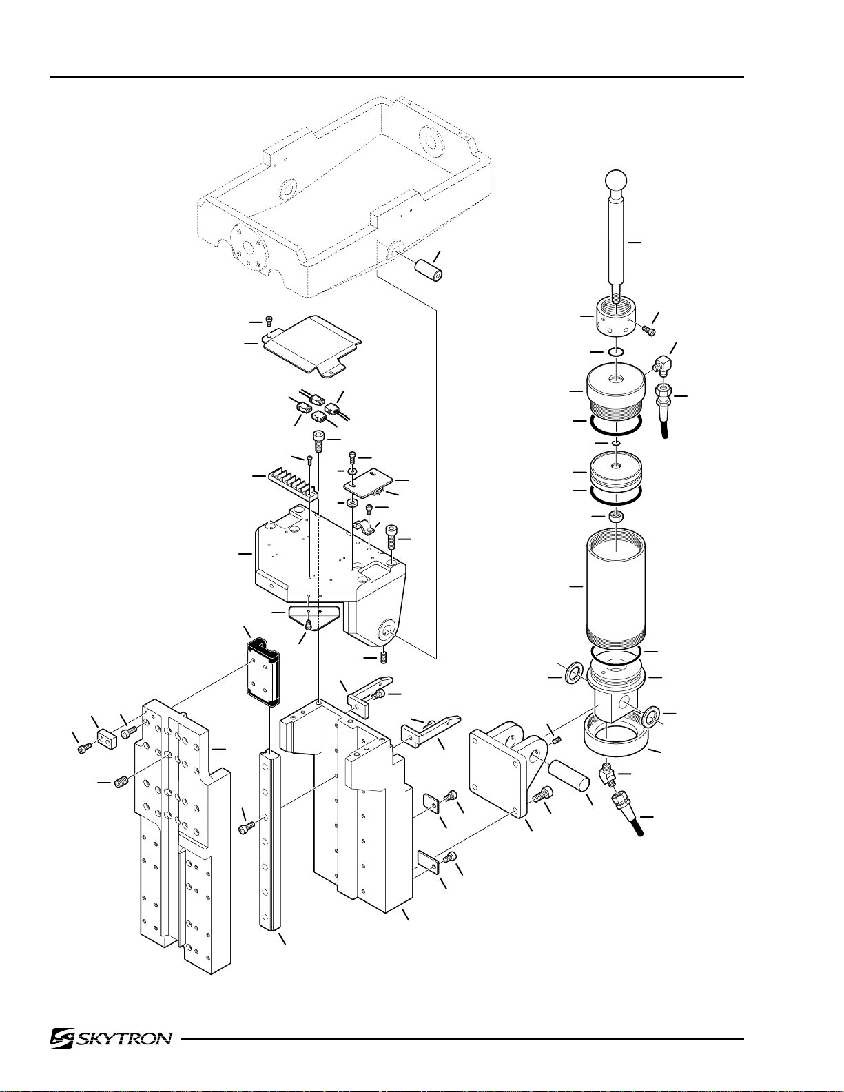
Page 26 9. TREND. CYLINDER & SUPPORT COLUMN ASSEMBLY (continued)
17
3
53
1
21
23
2
22
36
24
5
25
37
26
4
7
8
10
13
6
27
9
28
29
30
15
11
12
14
16
31
18
57
56
58
55
54
52
51
19
43
20
44
44
50
45
46
48
47
49
42
35
39
41
40
32
33
35
34
38
37
3600.0605.08

9. TREND. CYLINDER & SUPPORT COLUMN ASSEMBLY (continued)
Item Part No. Description Qty.
50 ------ SLIDER, section #1 (not available separately) ........................................................... 1
51 ------ GUIDE, slider bearing, slider section #1 (not available separately) .......................... 2
52 D6-010-38 BOLT, allen, M6 x 15 ................................................................................................... 14
53 ------ BEARING, slide (not available separately) ................................................................ 4
54 ------ SLIDER, section #2 (not available separately) .......................................................... 1
55 D6-010-38 BOLT, allen, M6 x 15 ................................................................................................... 16
56 ------ STOP (not available separately)................................................................................ 1
57 D6-036-21 BOLT, allen, M5 x 12 .................................................................................................... 2
58 D6-010-27 SCREW , set, M10 x 15................................................................................................ 16
Page 27

Page 28 10. SUPPORT COLUMN ASSEMBLY
21
22
23
24
25
11
7
12
26
27
9
28
29
10
6
7
8
5
4
14
15
13
30
31
6
32
33
34
3
35
36
2
16
17
18
20
37
38
1
19
3600.0605.09

10. SUPPORT COLUMN ASSEMBLY
Item Part No. Description Qty.
1 D6-036-23 SCREW, countersunk phillips, M6 x 10 ....................................................................... 4
2 D2-036-22 SHROUD, elevation, lower .......................................................................................... 1
3 D2-036-23 SHROUD, elevation, middle ........................................................................................ 1
4 D2-036-24 SHROUD, elevation, upper .......................................................................................... 1
5 D6-010-38 BOLT, allen, M6 x 15 ................................................................................................... 16
6 ------ BEARING, slide (not available separately) ................................................................. 8
7 ------ GUIDE, slider bearing , slider section #3 (not available separately) .......................... 4
8 D6-010-38 BOLT, allen, M6 x 15 ................................................................................................... 12
9 D6-044-89 BOLT, allen, M5 x 25 .................................................................................................... 2
10 ------ STOP (not available separately).................................................................................. 1
11 ------ SLIDER, section #3 (not available separately) ........................................................... 1
12 D6-010-38 BOLT, allen, M6 x 15 ................................................................................................... 12
13 ------ SLIDER, section #4 (not available separately) ........................................................... 1
14 D6-010-38 BOLT, allen, M6 x 15 ................................................................................................... 16
15 D6-010-27 SCREW , set, M10 x 15................................................................................................. 8
16 D6-035-16 BOLT, allen, M12 x 40 .................................................................................................. 4
17 D6-010-21 WASHER, lock, M12 .................................................................................................... 4
18 ------ HOSE, flexible (specify function) ................................................................................A/R
19 D4-010-31 FITTING, flexible hose ................................................................................................. 1
20 D6-010-38 BOLT, allen, M6 x 15 .................................................................................................... 2
D4-036-52 CYLINDER ASSEMBLY, elevation ............................................................................... 1
21 D4-036-53 •CUSHION, rubber ....................................................................................................... 1
22 ------ •CAP (not available separately) .................................................................................. 1
23 ------ •ROD, primary piston (not available separately) ......................................................... 1
24 D4-010-56 •O-RING, P-10A ........................................................................................................... 1
25 ------ •PISTON, primary (not available separately)............................................................... 1
26 D4-036-57 •RING, back-up ............................................................................................................ 1
27 D4-050-01 •O-RING, P-29.............................................................................................................. 1
28 D6-010-42 •WASHER, lock, M10 ................................................................................................... 1
29 D6-010-43 •NUT, hex, M10 ............................................................................................................ 1
30 ------ •TUBE, secondary piston (not available separately)................................................... 1
31 D4-034-68 •O-RING, P-31.............................................................................................................. 1
32 ------ •PISTON, secondary (not available separately) .......................................................... 1
33 D4-036-63 •RING, back-up ............................................................................................................ 1
34 D4-010-54 •O-RING, P-36.............................................................................................................. 1
35 ------ •CAP, elevation tube (not available separately) .......................................................... 1
36 ------ •TUBE, elevation cylinder (not available separately).................................................. 1
37 D4-040-40 •O-RING, P-39.............................................................................................................. 1
38 ------ •BASE, elevation cylinder (not available separately).................................................. 1
Page 29
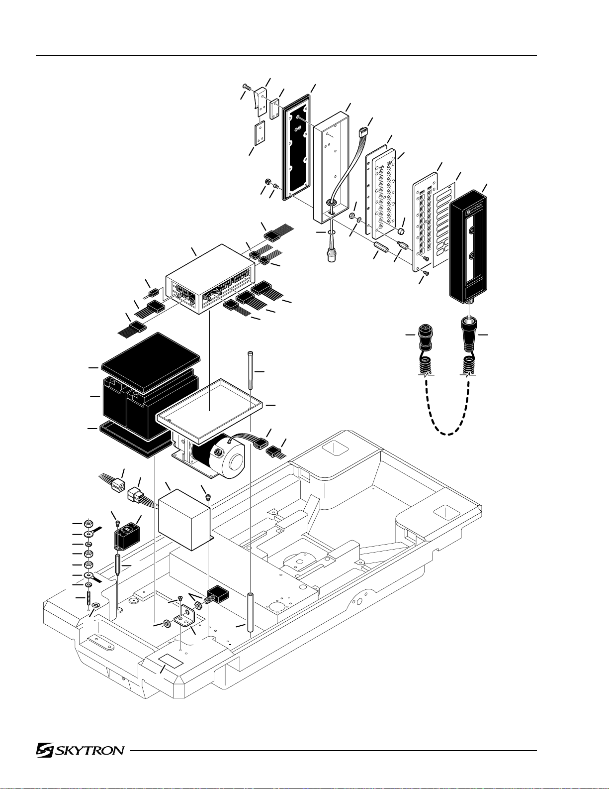
Page 30 11. ELECTRICAL COMPONENTS
30
31
32
23
2
3
1
5
8
9
13
14
4
18
20
21
25
6
24
7
10
26
12
11
15
16
17
19
27
28
29
22 22
52
53
54
52
52
53
54
55
33
34
35
56
49
48
51
47
50
44
46
42
36
37
38
39
45
41
40
43
57
3600.0605.11

11. ELECTRICAL COMPONENTS
Item Part No. Description Qty.
D5-036-01 PENDANT CONTROL ASSEMBLY .............................................................................. 1
1 D6-032-33 •SCREW, pendant hook, M4 x 12................................................................................ 3
2 D5-034-07 •HOOK, pendant .......................................................................................................... 1
3 D5-034-08 •PLATE, pendant hook ................................................................................................. 1
4 ------ •INSERT, pendant hook (part of D5-034-07)............................................................... 1
5 D5-034-10 •BACK PLATE .............................................................................................................. 1
6 D6-034-07 •PLUG, rubber.............................................................................................................. 8
7 D6-010-79-1 •SCREW, M3 x 5 (plated) ............................................................................................A/R
8 D5-034-11 •HOUSING ................................................................................................................... 1
9 D5-034-12 •CONNECTOR ASSEMBLY, 7-pin, female................................................................... 1
10 ------ •O-RING, connector assembly ..................................................................................... 1
11 D6-034-08 •NUT, M3 (plated)........................................................................................................A/R
12 D6-034-09 •WASHER, M3 .............................................................................................................A/R
13 D5-036-34 •CIRCUIT BOARD........................................................................................................ 1
14 D5-067-18 •PLATE, circuit board mounting ................................................................................... 1
15 D6-034-12 •STAND-OFF ...............................................................................................................A/R
16 D6-034-10 •BUTTON.....................................................................................................................A/R
17 D6-034-11 •STAND-OFF ...............................................................................................................A/R
18 D5-067-19 •COVER, circuit board mounting plate......................................................................... 1
19 D6-010-79-1 •SCREW, M3 x 5 (plated) ............................................................................................A/R
20 D5-036-35 •FACEPLATE, pendant control ..................................................................................... 1
21 D5-036-36 •COVER, rubber ........................................................................................................... 1
22 D5-034-18 •CORD ASSEMBLY...................................................................................................... 1
23 D5-036-02 RELAY BOX.................................................................................................................. 1
24 D5-067-24 CONNECTOR, 12-pin, female (CN-3) ........................................................................ 1
25 D5-067-25 CONNECTOR, 7-pin, female (CN-8) .......................................................................... 1
26 D5-067-26 CONNECTOR, 7-pin, female (CN-7) .......................................................................... 1
27 D5-067-27 CONNECTOR, 20-pin, female (CN-1B)...................................................................... 1
28 D5-067-28 CONNECTOR, 16-pin, female (CN-1A)...................................................................... 1
29 D5-067-29 CONNECTOR, 16-pin, female (CN-2) ........................................................................ 1
30 D5-067-30 CONNECTOR, 26-pin, female (CN-10) ...................................................................... 1
31 D5-067-31 CONNECTOR, 12-pin, female (CN-4) ........................................................................ 1
32 D5-067-32 CONNECTOR, 2-pin, female ...................................................................................... 1
33 D1-032-21 COVER, battery............................................................................................................ 1
34 D5-032-43 BATTERY, 12V .............................................................................................................. 2
35 D1-032-20 TRAY, battery................................................................................................................ 1
36 D6-032-21 BOLT, allen, M5 x 105 .................................................................................................. 2
37 D1-032-23 TRAY, relay box ............................................................................................................ 1
38 D5-067-33 CONNECTOR, 4-pin, female ....................................................................................... 1
39 D5-067-34 CONNECTOR, 4-pin, male .......................................................................................... 1
40 D1-032-22 STAND-OFF ................................................................................................................. 2
41 D5-067-36 CIRCUIT BREAKER ASSEMBLY, 15A ......................................................................... 1
42 D6-067-23 SCREW, phillips, countersunk, M4 x 8 ........................................................................ 2
43 D5-067-35 BRACKET, circuit breaker ............................................................................................ 1
44 D6-067-22 NUT.............................................................................................................................. 1
45 D6-010-28 BOLT, allen, M5 x 6 ...................................................................................................... 2
46 D5-067-22 CAPACITOR / rectifier unit ........................................................................................... 1
47 D5-032-59 CONNECTOR, 6-pin, female ....................................................................................... 1
48 D5-032-60 CONNECTOR, 6-pin, male .......................................................................................... 1
49 D6-060-07 BOLT, allen, M4 x 8 ...................................................................................................... 2
Page 31

Page 32 11. ELECTRICAL COMPONENTS (continued)
30
31
32
23
2
3
1
5
8
9
13
14
4
18
20
21
25
6
24
7
10
26
12
11
15
16
17
19
27
28
29
22 22
52
53
54
52
52
53
54
55
33
34
35
56
49
48
47
51
50
44
46
42
36
37
38
39
45
41
40
43
57
3600.0605.11

11. ELECTRICAL COMPONENTS (continued)
Item Part No. Description Qty.
50 D5-034-49 BUZZER ....................................................................................................................... 1
51 D6-034-13 STAND-OFF ................................................................................................................. 2
52 D6-010-76 NUT, hex, M5................................................................................................................ 3
53 ------ GROUND WIRE ..........................................................................................................A/R
54 D6-017-28 WASHER, lock, M5....................................................................................................... 2
55 D6-035-02 SCREW , set, M5 x 25................................................................................................... 1
56 D6-034-21 DECAL, ground ............................................................................................................ 1
57 D6-036-24 LABEL, voltage requirement ........................................................................................ 1
Page 33
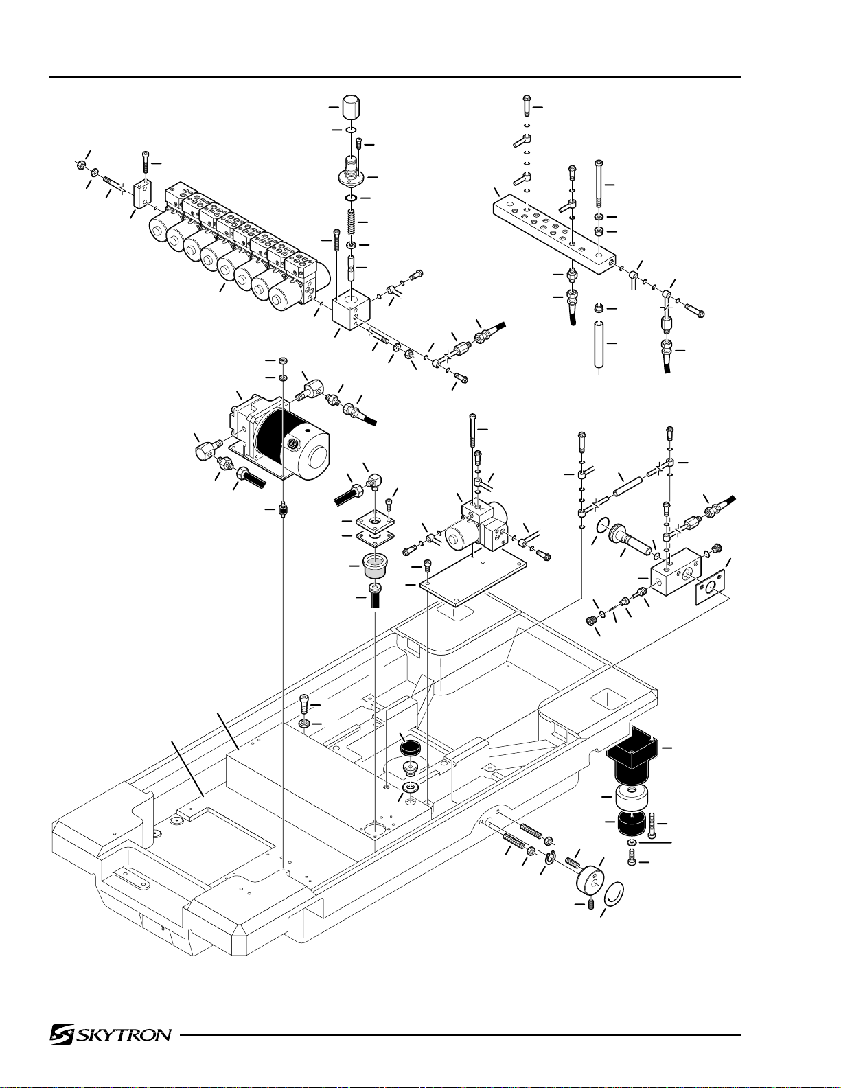
Page 34 12. HYDRAULIC VALVES & FITTINGS
14
13
15
19
20
61
62
18
63
60
58
59
64
57
17
16
1
22
2
3
4
23
26
5
6
7
7
24
27
28
30
11
25
28
29
31
10
12
11
21
8
15
12
14
13
56
9
52
67
68
69
63
70
65
66
55
54
34
53
21
30
34
35
40
33
36
44
38
43
37
42
32
31
41
39
74
73
71
72
75
76
77
45
46
47
50
48
82
81
51
49
83
80
79
78
3600.0605.12

12. HYDRAULIC VALVES & FITTINGS
Item Part No. Description Qty.
-- D4-031-23 PRESSURE RELIEF VALVE ........................................................................................ 1
1 ------ •CAP, pressure relief valve (not available separately) ................................................ 1
2 D4-031-67 •O-RING, P-10.............................................................................................................. 1
3 D6-034-14 •SCREW....................................................................................................................... 3
4 ------ •BOD Y, pressure relief valve (not available separately).............................................. 1
5 D4-010-51 •O-RING, P-16.............................................................................................................. 1
6 D4-031-12 •SPRING ...................................................................................................................... 1
7 D4-031-23-4 •VALVE, relief, 5mm dia. (steel).................................................................................... 1
8 ------ •HOUSING, relief valve (5mm dia. valve) (not available separately) .......................... 1
9 D4-010-24 BOLT, plumbing, M6 ....................................................................................................A/R
10 D4-010-08 O-RING, P-7 ................................................................................................................A/R
11 D4-032-49 OIL LINE......................................................................................................................A/R
12 D4-032-64 HOSE, flexible, pump return ........................................................................................ 1
13 D6-010-76 NUT, M5 ....................................................................................................................... 4
14 D6-010-77 WASHER, lock, M5....................................................................................................... 4
15 D6-032-14 STUD, M5 x 345 ........................................................................................................... 2
16 D4-010-52 O-RING, P-4 ................................................................................................................A/R
17 D6-010-65 BOLT, allen, M5 x 35 .................................................................................................... 4
18 D4-067-33 ELECTRO / MINI VALVE ASSEMBLY, (3-way), 24vdc, elevation ................................A/R
D4-067-35 ELECTRO / MINI VALVE ASSEMBLY, (4-way), 24vdc ................................................A/R
19 D4-010-40 CAP, end ...................................................................................................................... 1
20 D6-010-64 BOLT, allen, M5 x 40 .................................................................................................... 2
21 ------ OIL LINE (specify function) .........................................................................................A/R
22 D4-010-26 BOLT, plumbing, M6 (long) .........................................................................................A/R
23 D4-036-66 TERMINAL, plumbing .................................................................................................. 1
24 D4-010-31 FITTING, flexible hose ................................................................................................A/R
25 ------ HOSE, flexible (specify function) ................................................................................A/R
26 D6-032-13 BOLT, allen, M6 x 140 .................................................................................................. 2
27 D6-010-85 WASHER, flat, M6 ........................................................................................................ 2
28 D6-031-16 BUSHING, isolation ..................................................................................................... 4
29 D4-032-81 STAND-OFF ................................................................................................................. 2
30 ------ OIL LINE (specify function) .........................................................................................A/R
31 ------ FLEXIBLE HOSE (specify function) ............................................................................A/R
32 ------ OIL LINE (specify function) .........................................................................................A/R
33 D4-032-51 FLEXIBLE TUBE .......................................................................................................... 1
34 ------ OIL LINE, (specify function) ........................................................................................A/R
-- D4-017-15 EMERGENCY BRAKE RELEASE ASSEMBLY ........................................................... 1
35 D4-041-15 •O-RING, P18 ............................................................................................................... 1
36 D4-017-19 •PLUNGER................................................................................................................... 1
37 D4-010-08 •O-RING, P-7 ................................................................................................................ 1
38 D4-017-16 •BLOCK, emergency brake release ............................................................................ 1
39 D6-017-34 •PLUG, cap................................................................................................................... 2
40 D4-010-08 •O-RING, P-7 ................................................................................................................ 2
41 D6-017-32 •SPACER ...................................................................................................................... 1
42 D4-017-18 •PILOT PLUNGER ....................................................................................................... 1
43 D4-017-17 •VALVE ......................................................................................................................... 1
44 D6-017-33 •SPRING ...................................................................................................................... 1
45 D6-035-06 •SCREW, set, M6 x 25.................................................................................................. 2
46 D6-010-41 •NUT, hex, M6 .............................................................................................................. 2
47 D6-017-31 •RING, retaining ........................................................................................................... 1
48 D6-010-87 •SCREW, set, M6 x 20.................................................................................................. 1
49 D6-017-30 •KNOB .......................................................................................................................... 1
Page 35

Page 36
12. HYDRAULIC VALVES & FITTINGS (continued)
14
13
15
19
20
61
62
18
63
60
58
59
64
57
17
16
1
22
2
3
4
23
26
5
6
7
7
24
27
28
30
11
25
28
29
31
10
12
11
21
8
15
12
14
13
56
9
52
67
68
69
63
70
65
66
55
54
34
53
21
30
34
35
40
33
36
44
38
43
37
42
32
31
41
39
74
73
71
72
75
76
77
45
46
47
50
48
82
81
51
49
83
80
79
78
3600.0605.12

12. HYDRAULIC VALVES & FITTINGS (continued)
Item Part No. Description Qty.
50 D6-060-38 •SCREW, set, M5 x 10.................................................................................................. 1
51 D6-017-29 •DECAL ........................................................................................................................ 1
52 D6-010-99 BOLT, allen, M5 x 60 .................................................................................................... 2
53 D4-067-34 ELECTRO / MINI VALVE ASSEMBLY (3-way), 24vdc, brake (blue dot) ....................A/R
54 D6-010-73 BOLT, allen, M6 x 12 .................................................................................................... 4
55 D1-036-04 PLATE, electro / mini valve assembly mounting .......................................................... 1
56 D6-032-63 FITTING, flexible hose ................................................................................................. 1
57 D5-034-33 FITTING ........................................................................................................................ 1
58 D6-010-76 NUT, hex, M5................................................................................................................ 4
59 D6-010-77 WASHER, lock, M5....................................................................................................... 4
60 D4-034-32 PUMP / MOTOR ASSEMBLY ....................................................................................... 1
61 D5-034-33 FITTING ........................................................................................................................ 1
62 D4-032-67 FITTING, flexible hose ................................................................................................. 1
63 D4-032-66 TUBE, suction .............................................................................................................. 1
64 D4-031-65 ISOLATION MOUNT , motor.......................................................................................... 4
65 D4-030-12 FITTING, hydraulic, 90°................................................................................................ 1
66 D6-010-67 BOLT, allen, M5 x 15 .................................................................................................... 4
67 D4-031-14 COVER, oil tank ........................................................................................................... 1
68 D4-031-13 GASKET, oil tank cover ................................................................................................ 1
69 D4-031-11 STRAINER, oil ............................................................................................................. 1
70 D4-030-19 TUBE, induction ........................................................................................................... 1
71 D6-010-51 BOLT, allen, M6 x 10 .................................................................................................... 2
72 D6-010-85 WASHER, flat, M6 ........................................................................................................ 2
73 D4-036-64 RESERVOIR, oil tank................................................................................................... 1
74 D4-036-65 PLATE, oil tank receiving ............................................................................................. 1
75 D4-010-39 CAP, oil filler ................................................................................................................. 1
76 D4-010-38 FITTING, oil filler .......................................................................................................... 1
77 D4-010-37 GASKET, oil filler .......................................................................................................... 1
78 D6-010-30 BOLT, allen, M6 x 20 .................................................................................................... 4
79 D6-010-36 WASHER...................................................................................................................... 4
80 D6-010-39 BOLT, allen, M6 x 45 ................................................................................................... 16
81 D4-031-96 PAD, brake, self-leveling, hard..................................................................................... 2
D4-031-97 PAD, brake, self-leveling, soft ...................................................................................... 2
82 D4-031-95-1 SEAT, brake, rubber ..................................................................................................... 4
83 D4-035-47 CYLINDER ASSEMBLY, brake..................................................................................... 4
Page 37

Page 38 13. ELECTRO / MINI VALVE ASSEMBLY
3600.0605.13
10
2
1
3
4
5
6
7
8
9
11
13
12
14
15
16
20
19
14
29
28
27
26
25
21
24
22
23
22
23
17
21 19
24
25
26
18
18
28
29
27

13. ELECTRO / MINI VALVE ASSEMBLY
Item Part No. Description Qty.
1 D6-010-65 BOLT, allen, M5x35 ...................................................................................................... 2
2 D4-010-41 PLUG, cap...................................................................................................................A/R
3 D4-010-08 O-RING, P-7 ................................................................................................................A/R
4 D4-010-42 SPRING, return ...........................................................................................................A/R
5 D4-010-25 VALVE, non-retur n ...................................................................................................... A/R
6 ----- V ALVE BLOCK, 4-way (not available separately) ......................................................A/R
----- VALVE BLOCK, 3-way (not available separately) ......................................................A/R
7 ----- BALL, check (not available separately) ......................................................................A/R
8 D4-050-12 O-RING, P-5 ................................................................................................................A/R
9 ----- SPRING (not available separately) ............................................................................A/R
10 ----- PLUG (not available separately) ................................................................................A/R
11 D4-010-20 O-RING, P-3 ................................................................................................................A/R
12 ----- VALVE, needle, speed control (not available separately)..........................................A/R
13 D4-010-19 O-RING, P-6 ................................................................................................................A/R
14 D4-010-01 O-RING, P-8 ................................................................................................................A/R
15 ----- PILOT PLUNGER (not available separately) .............................................................A/R
16 ----- VALVE BLOCK (not available separately) ..................................................................A/R
17 ----- VALVE BLOCK (not available separately) ..................................................................A/R
18 D4-010-52 O-RING, P-4 ................................................................................................................A/R
19 D4-010-51 O-RING, P16 ...............................................................................................................A/R
20 ----- SPOOL VALVE (not availab le separately) ..................................................................A/R
21 D4-034-28 RETAINER, spool valve .............................................................................................. A/R
22 D4-034-29 SPRING, return, spool valve .......................................................................................A/R
23 ----- GUIDE, bushing (not available separately)................................................................A/R
24 D4-010-14 O-RING, P-12 ..............................................................................................................A/R
25 D4-034-31 PLUNGER, spool valve .............................................................................................. A/R
26 D5-067-37 SOLENOID, 24VDC ....................................................................................................A/R
D5-067-02 •PIN, connector ...........................................................................................................A/R
27 D5-034-37 HOUSING, solenoid .................................................................................................... A/R
28 D6-010-78 WASHER, lock, M3....................................................................................................... 8
29 D6-010-79 SCREW, phillips, M3x5 ................................................................................................ 8
Page 39

Page 40
14. BASE ASSEMBLY
5
2
3
1
41
11
40
39
10
9
13
38
4
20
6
7
8
19
12
17
18
43
16
44
14
15
22
21
45
36
34
35
46
37
33
32
42
28
27
31
30
29
24
23
26
25
3600.0605.14

14. BASE ASSEMBLY
Item Part No. Description Qty.
1 D6-036-01 SCREW, phillips, roundhead, M4 x 8 .......................................................................... 4
2 D5-034-38 FACEPLATE, 6-switch ................................................................................................. 1
3 D5-034-39 COVER, switch assembly ............................................................................................ 1
4 D5-034-40 SWITCH PLATE ASSEMBLY........................................................................................ 1
D5-034-41 •SWITCH, toggle, 2-position ........................................................................................ 6
5 D1-034-01 COVER, service access ............................................................................................... 1
6 D6-067-23 SCREW, phillips, countersunk, M4 x 8 ........................................................................ 4
7 D6-010-51 BOLT, allen, M6 x 10 .................................................................................................... 2
8 D6-010-85 WASHER, flat, M6 ........................................................................................................ 2
9 D1-034-03 FRAME ......................................................................................................................... 1
10 D1-034-04 GASKET ....................................................................................................................... 1
11 D3-036-01 HOUSING, base........................................................................................................... 1
12 D6-010-67 BOLT, allen, M5 x 15 ................................................................................................... 10
13 D6-065-21 DECAL, grounding reliability ....................................................................................... 1
14 D6-065-22 DECAL, CAUTION, electric shock ............................................................................... 1
15 D6-065-23 DECAL, DANGER, EXPLOSION HAZARD 1 .............................................................. 1
16 D6-065-24 DECAL, DANGER, EXPLOSION HAZARD 2 .............................................................. 1
17 D6-065-25 DECAL, serial / model number .................................................................................... 1
18 D6-017-05 DECAL, type B equipment ........................................................................................... 2
19 D6-065-26 DECAL, emergency brake release .............................................................................. 1
20 D6-067-23 SCREW, phillips, countersunk, M4 x 8 ........................................................................ 1
21 D6-010-51 BOLT, allen, M6 x 10 .................................................................................................... 1
22 D6-065-28 SPRING........................................................................................................................ 1
23 D1-010-30 CASTER, 105HBP ....................................................................................................... 4
24 D6-010-96 BOLT, allen, M10 x 20 ................................................................................................. 16
25 D6-034-20 EQUALIZA TION TERMINAL......................................................................................... 1
26 D6-034-21 DECAL, equalization terminal ..................................................................................... 1
27 D6-034-05 SCREW, phillips, M6 x 7 (plated)................................................................................. 4
28 D5-034-47 COVER, w/ chain .......................................................................................................... 1
29 D6-060-41 SCREW, allen, M4 x 3.................................................................................................. 4
30 D1-036-01 FACEPLATE ................................................................................................................. 1
31 D5-034-44 CONNECTOR, 7-pin, female ....................................................................................... 1
32 D1-036-02 BRACKET .................................................................................................................... 1
33 D5-067-39 BATTERY INDICATOR ASSEMBLY ............................................................................. 1
34 D6-067-25 SCREW ........................................................................................................................ 2
35 D5-067-38 CONNECTOR, 12-pin, female ..................................................................................... 1
36 D6-010-51 BOLT, allen, M6 x 10 .................................................................................................... 3
37 D6-010-40 WASHER, lock, M6....................................................................................................... 3
38 D5-066-30 CONNECTOR, 3-prong ............................................................................................... 1
39 D5-066-32 COVER, w/ chain .......................................................................................................... 1
40 D6-034-05 SCREW, phillips, M6 x 7 (plated)................................................................................. 2
41 D5-066-31 POWER CORD ASSEMBLY ........................................................................................ 1
42 D5-034-46 SWITCH, on / off (includes cover)................................................................................ 1
43 D5-032-58 TRANSFORMER.......................................................................................................... 1
44 D6-032-17 SCREW, phillips ........................................................................................................... 4
45 D6-032-18 BOLT, allen ................................................................................................................... 4
46 D1-036-03 PLATE, transformer mounting ...................................................................................... 1
Page 41

Page 42
15. BASE ASSEMBLY - IR REMOTE
1
27
28
29
11
2
5
3
4
8
6
17
7
9
12
10
15
13
14
18
19
26
30
31
25
16
38
32
33
34
24
36
35
21
22
23
50
49
48
20
51
52
53
42
41
40
46
39
47
37
44
43
45
55
54
3600.0605.15

15. BASE ASSEMBLY - IR REMOTE
Item Part No. Description Qty.
1 D6-036-01 SCREW, phillips, round head, M4 x 8 ......................................................................... 4
2 D5-034-38 FACEPLATE, 6-switch .................................................................................................. 1
3 D5-034-39 COVER, switch assembly ............................................................................................ 1
4 D5-034-40 SWITCH PLATE ASSEMBLY........................................................................................ 1
D5-034-41 •SWITCH, toggle, 2-position ........................................................................................ 6
5 D1-067-02 COVER, service access ............................................................................................... 1
6 D6-067-23 SCREW, phillips, countersunk, M4 x 8 ........................................................................ 4
7 D1-034-03 FRAME ......................................................................................................................... 1
8 D6-067-23 SCREW, phillips, countersunk, M4 x 8 ....................................................................... 16
9 D6-010-51 BOLT, allen, M6 x 10 .................................................................................................... 2
10 D6-010-85 WASHER, flat, M6 ........................................................................................................ 2
11 D1-034-04 GASKET ....................................................................................................................... 1
12 D5-067-43 COVER, infrared sensor .............................................................................................. 4
13 D5-067-44 BRACKET, infrared sensor circuit board ..................................................................... 4
14 D5-067-45 CIRCUIT BOARD, infrared sensor............................................................................... 4
15 D6-035-04 SCREW, phillips, button head, M4 x 8......................................................................... 8
16 D5-067-46 CONNECTOR, 16-pin, female ..................................................................................... 4
17 D6-067-23 SCREW, phillips, countersunk, M4 x 8 ........................................................................ 4
18 D3-036-01 HOUSING, base........................................................................................................... 1
19 D6-065-26 DECAL, emergency brake release .............................................................................. 1
20 D6-017-05 DECAL, type B equipment ........................................................................................... 2
21 D6-065-25 DECAL, serial / model number .................................................................................... 1
22 D6-065-24 DECAL, DANGER, EXPLOSION HAZARD 2 .............................................................. 1
23 D6-065-23 DECAL, DANGER, EXPLOSION HAZARD 1 .............................................................. 1
24 D6-065-22 DECAL, CAUTION, ELECTRIC SHOCK...................................................................... 1
25 D6-010-67 BOLT, allen, M5 x 15 ................................................................................................... 10
26 D6-065-21 DECAL, grounding reliability ....................................................................................... 1
27 D5-066-31 POWER CORD ASSEMBLY ........................................................................................ 1
28 D6-034-05 SCREW, phillips, M6 x 7 (plated)................................................................................. 2
29 D5-066-32 COVER, w/ chain ......................................................................................................... 1
30 D5-066-30 CONNECTOR, 3-prong ............................................................................................... 1
31 D1-036-02 BRACKET .................................................................................................................... 1
32 D6-010-51 BOLT, allen, M6 x 10 .................................................................................................... 3
33 D6-010-40 WASHER, lock, M6....................................................................................................... 3
34 D6-067-25 SCREW ........................................................................................................................ 2
35 D5-067-38 CONNECTOR, 12-pin, female ..................................................................................... 1
36 D5-067-39 BATTERY INDICATOR ASSEMBLY ............................................................................. 1
37 D5-034-44 CONNECTOR, 7-pin, female ....................................................................................... 1
38 D1-036-01 FACEPLATE ................................................................................................................. 1
39 D6-060-41 SCREW, allen, M4 x 3.................................................................................................. 4
40 D6-034-05 SCREW, phillips, M6 x 7 (plated)................................................................................. 4
41 D5-034-47 COVER, w/ chain .......................................................................................................... 1
42 D5-034-46 SWITCH, on / off (w/ cover) .......................................................................................... 1
43 D5-067-48 WIRE HARNESS.......................................................................................................... 1
44 D5-067-47 IR BATTERY PACK....................................................................................................... 1
45 D6-010-70 BOLT, allen, M5 x 10 .................................................................................................... 2
46 D6-034-21 DECAL, equalization terminal ..................................................................................... 1
47 D6-034-20 EQUALIZA TION TERMINAL......................................................................................... 1
48 D1-036-03 PLATE, transformer mounting ...................................................................................... 1
49 D6-032-18 BOLT, allen ................................................................................................................... 4
50 D6-032-17 SCREW, phillips ........................................................................................................... 4
Page 43

Page 44
15. BASE ASSEMBLY - IR REMOTE (continued)
1
27
28
29
11
2
5
3
4
8
6
17
7
9
12
10
15
13
14
18
19
26
30
31
25
16
38
32
33
34
24
36
35
21
22
23
50
49
48
20
51
52
53
42
41
40
46
39
47
37
44
43
45
55
54
3600.0605.15

15. BASE ASSEMBLY - IR REMOTE (continued)
Item Part No. Description Qty.
51 D5-032-58 TRANSFORMER.......................................................................................................... 1
52 D6-065-28 SPRING........................................................................................................................ 1
53 D6-010-51 BOLT, allen, M6 x 10 .................................................................................................... 1
54 D1-010-30 CASTER, 105HBP ....................................................................................................... 4
55 D6-010-96 BOLT, allen, M10 x 20 ................................................................................................. 16
Page 45

Page 46
Item Part No . Description Qt y.
6-050-02 GAUGE, oil pressure ...............................................................................................A/R
D6-010-89 GREASE, slider..................................................................................................... 2.8 oz
D6-010-90 OIL, hydraulic ........................................................................................................... Qt
D4-011-02 HOSE, hydraulic, specify length .............................................................................A/R
D4-011-03 FITTING, hydraulic hose end.................................................................................. A/R

5000 36th Street S.E. • Grand Rapids, MI 49512
1.800.SKYTRON • 1.616.957.0500 • FAX 1.616.957.5053
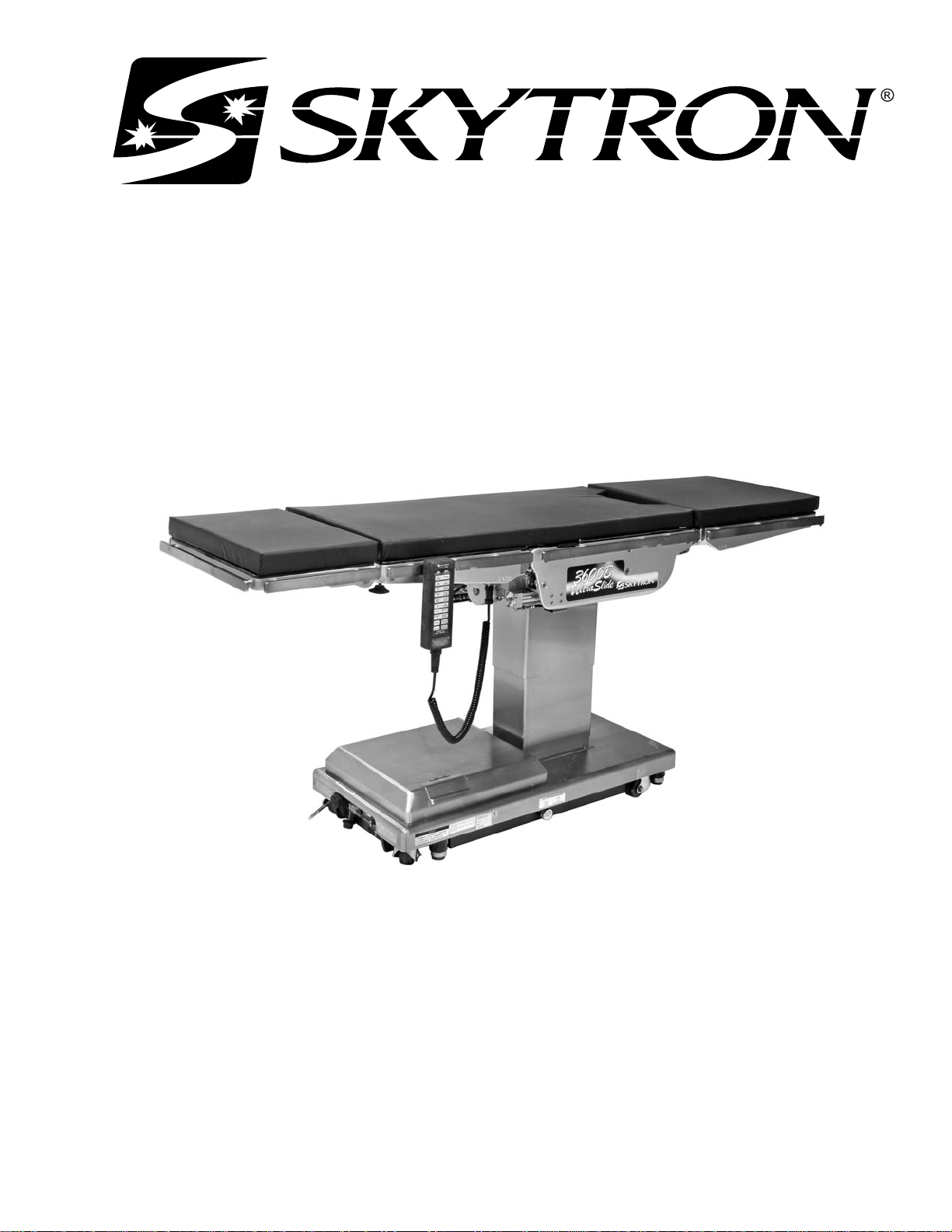
SURGICAL TABLE
MAINTENANCE MANUAL
REV 1/07
MODEL 3600B ULTRASLIDE


Page 1
TABLE OF CONTENTS
Title Page
Basic Recommended Tools & Maintenance Procedures ......................................................................... 3
Equipment Lables & Specifications .......................................................................................................... 4
Table & Electrical Specifications .............................................................................................................. 5
SECTION I HYDRAULIC SYSTEM......................................................................................................... 7
1-1. General ......................................................................................................................................... 7
1-2. Component Operation .................................................................................................................. 8
a. Motor/Pump Operation ............................................................................................................. 8
b. Pressure Relief Valve ............................................................................................................... 8
c. Mini-Valves ............................................................................................................................... 9
d. Hydraulic Cylinders (Slave Cylinders) .................................................................................... 11
e. Elevation Cylinder Return Circuit ........................................................................................... 13
f. Brake System ......................................................................................................................... 13
g. Emergency Brake Release..................................................................................................... 14
h. Flex/Reflex System ................................................................................................................. 14
1-3. Hydraulic Adjustments ................................................................................................................ 15
a. Fluid Level .............................................................................................................................. 15
b. Bleeding The Hydraulic System ............................................................................................. 15
c. Pressure Relief Valve ............................................................................................................. 15
d. Speed Controls....................................................................................................................... 16
SECTION II MECHANICAL TABLE ADJUSTMENTS........................................................................... 17
2-1. Back Section Gear Mesh Adjustment ......................................................................................... 17
2-2. Hydraulic Cylinder Adjustment .................................................................................................... 17
a. Back Section .......................................................................................................................... 17
b. Leg Section ............................................................................................................................ 18
c. Trendelenburg Cylinder Ball Joint ........................................................................................... 18
2-3. Head Section Adjustment ........................................................................................................... 18
2-4. Slide Roller Adjustment ............................................................................................................... 19
2-5. Side Rails ..................................................................................................................................... 19
2-6. Casters .........................................................................................................................................19
SECTION III HYDRAULIC TROUBLESHOOTING ............................................................................... 21
3-1. Precautions ................................................................................................................................. 21
3-2. Troubleshooting Notes ................................................................................................................ 21
3-3. ELEVATION DIAGNOSIS CHART ............................................................................................. 22
3-4. TRENDELENBURG DIAGNOSIS CHART ................................................................................. 23
3-5. LATERAL - TILT DIAGNOSIS CHART ....................................................................................... 24
3-6. FLEX SYSTEM DIAGNOSIS CHART .......................................................................................... 25
REV 1/07
Although current at the time of publication, SKYTRON’S policy of continuous development makes this
manual subject to change without notice.

Page 2
TABLE OF CONTENTS (continued)
Title Page
3-7. BACK SECTION DIAGNOSIS CHART ........................................................................................ 26
3-8. LEG SECTION DIAGNOSIS CHART .......................................................................................... 27
3-9. SLIDE DIAGNOSIS CHART ........................................................................................................ 28
3-10. KIDNEY LIFT DIAGNOSIS CHART............................................................................................ 29
3-11. BRAKE CIRCUIT DIAGNOSIS CHART...................................................................................... 30
3-12. Flexible Hose Identification and Placement ................................................................................ 31
3-13. Kidney Lift System ....................................................................................................................... 32
SECTION IV ELECTRICAL SYSTEM ................................................................................................... 34
4-1. General ....................................................................................................................................... 34
4-2. Components ............................................................................................................................... 34
SECTION V ELECTRICAL TROUBLESHOOTING ............................................................................... 36
5-1. General ....................................................................................................................................... 36
5-2. Troubleshooting Notes ................................................................................................................ 36
5-3. Main Switch ................................................................................................................................ 36
5-4. Batteries ...................................................................................................................................... 37
5-5. Capacitor / Rectifier / AC120V Transformer ................................................................................ 38
5-6. Pendant Control .......................................................................................................................... 39
5-7. Auxiliary Switches ....................................................................................................................... 41
5-8. Relay Box ................................................................................................................................... 42
5-9. Main Wire Harness Continuity Tests .......................................................................................... 44
5-10. Solenoids .................................................................................................................................... 45
5-11. Motor/Pump Assembly................................................................................................................ 46
5-12. Return-to-Level / Positioning Inhibit Micro-Switches ................................................................... 47
5-13. Micro-Switch Troubleshooting ..................................................................................................... 48
WARNING
Indicates a possibility of personal injury.
CAUTION
Indicates a possibility of damage to
equipment.
NOTE
Indicates important facts or helpful hints.

Page 3
BASIC RECOMMENDED TOOLS:
1/8". 1/4" STRAIGHT BLADE SCREWDRIVERS
#2 PHILLIPS SCREWDRIVER
HYDRAULIC PRESSURE GAUGE SKYTRON P.N. 6-050-02
METRIC ALLEN WRENCHES 1.5mm-8mm
ADJUSTABLE CRESCENT WRENCH
DIGITAL VOLTMETER, TRUE RMS
METRIC OPEN END WRENCHES 7mm-18mm
LEVEL (CARPENTERS)
GREASE GUN
BEARING GREASE P.N. D6-010-89-1
BASIC RECOMMENDED MAINTENANCE PROCEDURES
The basic items notes below should be inspected at a minimal interval period of 6 months (dependant on
usage). For optimal usage, safety and longevity of the product, have it serviced only by an authorized
Skytron representative with authentic Skytron replacement parts.
• Check Power Cord (if applicable)
• Check Pendant Control (if applicable)
• Check Oil Level in Reservoir
• Check For Hydraulic Leaks
• Check Pressure Relief Valve Setting
• Check All Table Functions
• Check Side Rails and Gravity Stops
• Check Velcro
• Check Lateral Tilt Housing Bolts
• Lubricate Elevation Slider Assembly with Mobilux EP (Extreme Pressure) Grease P/N D6-010-89-1
• Tighten X-Ray Top Stand-Offs, Use Blue Loc-Tite
• Lubricate Casters
• Check brake pads for wear and inspect brake cylinders for proper operation.
• Inspect the Trendelenburg Cylinder & Ball Joint Retainer Nut
Only facility-authorized Skytron trained, maintenance personnel should troubleshoot the
Skytron 3600B Surgical Table. Trouble shooting by unauthorized personnel could result
in personal injury or equipment damage.
How to contact us:
SKYTRON
5000 36th St. SE, Grand Rapids, MI 49512
PH: 1-800-759-8766 (SKY-TRON)
FAX: 616-957-5053

N
Page 4
TYPE B
EQUIPMENT
EQUIPMENT LABELS AND SPECIFICATIONS
INDICATES DANGEROUS VOLTAGE, 120 V, 60 Hz
CLASS I DEFIBRILLATION PROOF, TYPE B EQUIPMENT- IPX4 RATED.
INTERNALLY POWERED EQUIPMENT
PROTECTIVE GROUNDING.
IN ORDER TO ENSURE PROPER GROUNDING RELIABILITY,
THIS TABLE MUST BE CONNECTED TO A PROPERLY GROUNDED
HOSPITAL GRADE OUTLET.
CONNECTION FOR NEUTRAL CONDUCTOR SUPPLIED
UNIT TO BE USED ONLY IN SPECIFIED ENVIRONMENTAL CONDITIONS
TEMPERATURE: 15˚ - 30˚ C (60˚ - 85˚ F)
HUMIDITY: 30% - 60% RELATIVE HUMIDITY, NON CONDENSING
IPX4
V
A
HZ
AC VOLTAGE
ENCLOSURE CLASS
VOLTAGE RATING OF THE UNIT
AMPERAGE RATING OF THE UNIT
FREQUENCY OF THE UNIT
ATTENTION, CONSULT MANUAL FOR FURTHER INSTRUCTIONS.
INDICATES SPECIAL USER ATTENTION.
POWERED BY AC VOLTAGE
POWERED BY BATTERY
BATTERY TYPE:
SEALED
LEAD ACID 12V, VALVE REGULATED
16AH, 10HR (530W/10MIN)
15 AMP INTERNAL CIRCUIT BREAKER
15A

3600B UltraSlide General Purpose Surgical Table Specifications
14-1/2"
Page 5
60˚
90˚
12-1/2"
18-1/4" 25" 23"
14-1/2"
TOP VIEW
82"
5-3/4"
3"
5-3/4"
19-3/4"
22"
42-1/2" MAX
24" MIN
8-3/4"
40-3/4"
SIDE VIEW
ENTELA CERTIFIED
TO UL2601-1
CAN/CSA601.1, IEC 60601-2-46
Electrical Specifications
Power requirements
Current Leakage
Power Cord
19"
END VIEW
120 VAC, 60Hz, 450 Watts
Less than 100 micro amps
15 feet w/hospital grade
connector (removable)
SERIAL NUMBER TAG

Page 6

1-1. General
SECTION I HYDRAULIC SYSTEM
Page 7
The hydraulic system (with the exception of the
hydraulic cylinders and hoses) is contained within
the base of the table. The hydraulic valves and
pump are electrically controlled by the use of a
hand-held push button pendant control. The power
requirements for the table are 120 VAC, 5 amp, 60
Hz.
The table contains the following components. Refer to the block diagram (figure 1-1) for relationship.
a. Oil Reservoir - Main oil supply. Approximately
two quarts.
b. Motor/Pump Assembly - A positive displacement gear type pump provides the necessary oil
pressure and volume.
SLIDE
2
3
TRENDELENBURG
CYLINDER
4
TILT
CYLINDER
5
67
BACK SECTION
c. Pressure Relief Valve - Provides an alternate oil
path when the hydraulic cylinders reach the end of
their stroke.
d. Electro/Hydraulic Mini-Valve Assemblies -These
direct the fluid to the appropriate hydraulic cylinders.
e. Hydraulic Lines, Fittings, Connections - They
provide a path for the hydraulic oil.
f. Hydraulic Cylinders - They convert the hydraulic
fluid pressure and volume into mechanical motion.
1213
10
KIDNEY LIFT
11
89
LEG SECTION
ELEVATION
CYLINDER
(4) BRAKE ASSEMBLIES
1
4
PLUMBING
TERMINAL
MINI-
VALVES
1
ELEV SLIDE
2
5 79
3
1
4
2
5
3
10
8
6
11 12 13
2
6
8
10
9
7
7
KIDNEY
LEGBACKFLEXTILTTREND
MOTOR/
PUMP
ASSEMBLY
Figure 1-1. Hydraulic Block Diagram
EMERGENCY
BRAKE RELEASE
14
BRAKE
12
11
13
82205-101

Page 8
1-2. Component Operation
a. Motor/Pump Operation
The motor/pump assembly is a gear type pump
that provides the oil pressure and volume for the
entire hydraulic system. The pump has an inlet
side and an outlet side. The inlet side is connected
to the reservoir which provides the oil supply. The
reservoir has a very fine mesh screen strainer
which prevents foreign material from entering the
oil system.
The output line of the pump is connected to the
main oil galley which is internal and common to all
the hydraulic mini-valves and pressure relief valve.
Also, common to the hydraulic mini-valves and
pressure relief valve is an oil galley that internally
connects to the oil reservoir to provide a return path
for the hydraulic oil. See figure 1-2.
The main component of the valve is an adjustable
spring loaded plunger that when it is pushed off
from its seat by the oil pressure the oil then flows
back into the reservoir. See figure 1-4. Turning the
adjustment nut clockwise increases the amount of
oil pressure required to open the valve, and turning
it counterclockwise decreases the amount of oil
pressure. (See adjustment section for specification.)
PRESSURE RELIEF
ADJUSTMENT NUT
SPRING
LOADED
PLUNGER
PRESSURE
GAUGE
PRESSURE
MAIN PRESSURE
OIL GALLERY (internal)
MINI-VALVES
OIL RESERVOIR
MAIN RETURN
OIL GALLERY
(internal)
MOTOR/PUMP
ASSEMBLY
PRESSURE
RELIEF VALVE
PUMP
OUTLET
PUMP
INLET
82205-102
Figure 1-2.
b. Pressure Relief Valve
This device provides an alternate oil path back to
the reservoir when the hydraulic cylinders reach
the end of their stroke and the pump continues to
run. If this path were not provided, the pump motor
would stall because the oil cannot be compressed.
The pressure relief valve is directly connected to
the mini-valve bodies and shares both the common
internal main pressure oil galley, and the return oil
galley that internally connects to the reservoir. See
figure 1-3.
RETURN
82205-103
Figure 1-3. Pressure Relief Valve Not
Functioning
PRESSURE RELIEF
ADJUSTMENT NUT
SPRING
LOADED
PLUNGER
PRESSURE
GAUGE
OIL LINE
FROM
PUMP
OIL RESERVOIR
82205-104
Figure 1-4. Pressure Relief Valve Functioning

c. Mini-Valves
OIL RETURN
(RETURN)
OIL GALLERY
(PRESSURE)
SPOOL
VALVE
SOLENOID
PISTON
PILOT
PLUNGER
CHECK
VALVE
SPEED
CONTROL
BALL
VALVE
OIL LINE
OIL LINE
82205-105
Page 9
The operation of the mini-valves is identical for all
table functions except the elevation and brake
circuits. These two hydraulic circuits use a 3-way
(single check valve) type mini-valve. All other functions use a 4-way (dual check valve) type minivalve.
Either type mini-valve is controlled by two pushing
type, electrically operated solenoids. The solenoids push the spool valve (located in the lower
portion of the valve) one way or the other. This
motion opens the main supply galley (which has
pump pressure) allowing the oil to flow through the
various parts of the mini-valve to the function. The
spool valve also opens an oil return circuit which
allows the oil to return to the oil reservoir.
The main components of the mini-valve and their
functions are listed below:
1. Spool Valve - Opens the main oil galley
(pump pressure) to either mini-valve outlet depending on which direction the spool valve is
pushed. Also it provides a return path for the oil
returning back into the reservoir.
2. Pilot Plunger - There are two plungers in a
four-way mini-valve (one in a 3-way mini-valve),
one under each check valve. The purpose of the
pilot plungers is to mechanically open the return
check valve allowing the oil to return back into the
reservoir.
a slave cylinder than is allowed by the speed
control, the pressure relief valve opens and provides an alternate path for the pump oil to return to
the reservoir.
The following material depicts the three operating
positions of the mini-valve. The movement of the
slave cylinder piston (extend or retract) is determined by which port of the Mini-Valve is activated.
Mini-Valve in Neutral Position
(No fluid flow) See figure 1-5.
• Spool Valve Centered - This closes off both oil
pressure and oil return galleys.
• Pilot Plungers Both Closed -The pilot plungers control the opening of the check valves. If they
are closed, the check valves must be closed.
• Check Valves - Both check valves are closed
trapping the oil in the cylinder and oil lines.
• Speed Control - When the mini-valve is in the
neutral position, the speed control does not affect
anything.
3. Check Valve - Two are provided in each fourway mini-valve to seal the oil in the cylinders and oil
lines and prevent any movement of the table. One
check valve is provided in a 3-way mini-valve.
4. Speed Controls - There are two speed
controls in each 4-way mini-valve. They are needle
valve type controls which restrict the volume of oil
returning back into the reservoir, thereby controlling the speed of the table surface movement. A 3way mini-valve has only one speed adjustment.
The speed controls are always located in the return
oil circuit to allow the movement of the cylinder to be
controlled. Also, by using this control method, it
does not matter what size cylinder and piston is
used because the speed is controlled by restricting
the return oil. If the pump puts out more volume to
Figure 1-5. Mini-Valve in Neutral Position

Page 10
Mini-Valve Right Port Activated
(See figure 1-6)
Mini-Valve Left Port Activated
(See figure 1-7.)
Right Mini-Valve Port is Supply Line
Left Mini-Valve Port is Return Line
INLET OUTLET
82205-106
Figure 1-6. Mini-Valve Right Port Activated
• Spool Valve - Pushed to the left by electric
solenoid. This opens the internal oil pressure
galley allowing the fluid to go through the check
valve and on to the cylinder. Also, the spool valve
opens the oil return line providing an oil path
through the internal oil galley back to the reservoir.
Left Mini-Valve Port is Supply Line
Right Mini-Valve Port is Return Line
OUTLET
82205-107
INLET
Figure 1-7. Mini-Valve Left Port Activated
• Spool Valve -Pushed to the right by electric
solenoid. This opens the internal oil pressure
galley allowing the fluid to go through the check
valve and on to the cylinder. Also, the spool valve
opens the oil return line providing an oil path
through the internal oil galley back to the reservoir.
• Pilot Plunger Valve - Left pilot plunger valve
is pushed up by the incoming oil pressure mechanically opening the check valve located above it in the
return circuit. This action allows the oil from the
return side of the slave cylinder to go back into the
reservoir. The right pilot plunger valve is not
affected in this operation mode.
• Check Valves - Both check valves are opened
in this operation mode. The right check valve is
pushed open by the oil pressure created by the
pump. The oil then continues through the lines and
supplies the inlet pressure to move the slave
cylinder piston. The left check valve is held open
mechanically by the pilot plunger and allows the oil
from the return side of the slave cylinder to go
through the mini-valve back to the reservoir.
• Speed Control - The right speed control
(output side) does not have any effect in this
operation mode because the oil is routed around
the speed control through a bypass valve to the
output port. The left speed control controls the
speed of the table function by restricting the flow of
oil going back into the reservoir.
• Pilot Plunger Valve - Right pilot plunger valve
is pushed up by the incoming oil pressure mechanically opening the check valve located above it in the
return circuit. This action allows the oil from the
return side of the slave cylinder to go back into the
reservoir. The left pilot plunger valve is not
affected in this operation mode.
• Check Valves - Both check valves are opened
in this operation mode. The left check valve is
pushed open by the oil pressure created by the
pump. The oil then continues through the lines and
supplies the inlet pressure to move the slave
cylinder piston. The right check valve is held open
mechanically by the pilot plunger and allows the oil
from the return side of the slave cylinder to go
through the mini-valve back to the reservoir.
• Speed Control - The left speed control
(output side) does not have any effect in this
operation mode because the oil is routed around
the speed control through a bypass valve to the
output port. The right speed control controls the
speed of the table function by restricting the flow of
oil going back into the reservoir.

d. Hydraulic Cylinders (Slave Cylinders)
Page 11
There are several different types of hydraulic cylinders used in the table that activate the control
functions. With the exception of the elevation and
brake cylinders, all operate basically the same
way. The control functions are listed below.
Back Section ------ 2 double action cylinders
Leg Section ------- 2 double action cylinders
Trendelenburg ---- 1 double action cylinder
Lateral Tilt --------- 1 double action cylinder
Elevation ----------- 1 single action cylinder
Kidney Lift --------- 2 double action cylinders
Brakes -------------- 4 single action cylinders
Slide ----------------- 2 double action cylinders
1. Trendelenburg, Back Section and Leg Section Cylinders - The double action cylinders are
closed at one end and have a movable piston with
hydraulic fluid on both sides. Connected to this
piston is a ram or shaft that exits out of the other end
of the cylinder. Through the use of a ball and
socket, a gear, or clevis and pin arrangement, this
ram is connected to a movable table surface.
The movable surface can be moved one way or
the other by pumping hydraulic fluid into the cylinder on either side of the piston. Obviously, if oil is
pumped into one side of the cylinder, a return path
must be provided for the oil on the other side. See
figure 1-8.
BACK
SECTION
O-RING RAM PISTON
and the other is attached to the elevation column.
Hydraulic fluid is pumped into the same end of both
cylinders at the same time. The two cylinder
system allows the 23 inches of top slide to be
performed by a short cylinder system. See figure
1-9.
PISTON
RAM
PISTON
RAM
82205-109
Figure 1-9. Slide Cylinder Assy.
3. Lateral Tilt Assembly - The lateral tilt assembly consists of two cylinders, pistons and connecting rods. The connecting rods attach to the lateral
tilt lever which connects to the table center column
assembly. The cylinder housing attaches to the
table top and is attached to the center column
assembly by pivots. See figure 1-10.
The pistons and connecting rods are attached to a
non-movable surface. Therefore, when hydraulic
fluid is pumped into one side, the cylinder housing
itself moves around the lateral tilt lever causing the
table top to tilt to one side.
To tilt the table top in the opposite direction, fluid is
pumped into the opposite cylinder.
HYDRAULIC
LINE
HYDRAULIC
LINE
82205-108
Figure 1-8. Back Section Cylinder
2. Slide Cylinder Assembly - The longitudinal
slide system utilizes two double action cylinders
working in tandem. The cylinder housing contains
two piston and ram assemblies facing in opposite
directions. One ram is connected to the table top
CONNECTING RODS
PISTON
82205-110
LATERAL
TILT LEVER
Figure 1-10. Lateral Tilt Cylinder Assembly
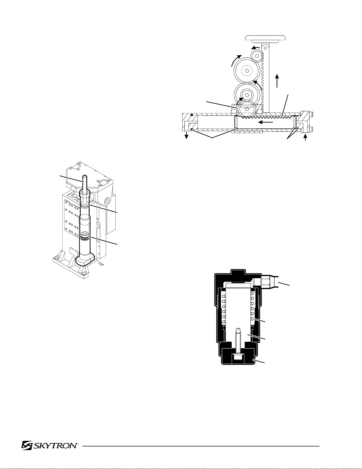
Page 12
4. Elevation Cylinder - This single action cylinder does not have hydraulic fluid on both sides of
the piston. It depends on the weight of the table top
assembly to lower it.
The cylinder is set in the center of the elevation
main column. The two stage cylinder is elevated by
the driven force of the oil pressure. When lowering,
the oil that is accumulated in the cylinder is returned
to the oil reservoir through the mini-valve due to the
table top weight.
A slider support assembly is used to support the
weight of the upper table section. A stainless steel
shroud covers the flexible hydraulic hoses and
slider. See figure 1-11.
PINION
GEAR
82205-112
O-RINGS
RAM
O-RINGS
ELEVATION
CYLINDER
PRIMARY
PISTON
SECONDARY
PISTON
SLIDER
ASSEMBLY
82205-111
Figure 1-11. Elevation Cylinder Assembly
5. Kidney Lift Cylinders - The two kidney lift
cylinders have a ram that has rack gear teeth cut
into the top surface. O-Rings on each end of the
ram allow the ram to also serve as the pistons.
The rack teeth cut into the top of the ram meshes
with a pinion gear. This gear meshes with other
gears to supply the up or down drive for the kidney
lift bars, depending on which direction the oil is
pumped into the cylinder. See figure 1-12.
Figure 1-12. Kidney Lift Cylinder Assembly
6. Brake Cylinders - The brake cylinders are
single action type similar to the elevation cylinder.
The movable piston's ram is connected to a brake
pad. See figure 1-13. Oil pumped into the top of the
cylinder pushes the piston down raising the table
base off its casters. An internal return spring on the
bottom of the piston, pushes the piston up to return
the oil through the mini-valve to the reservoir.
OIL LINE
RETURN SPRING
PISTON
BRAKE PAD
82205-113
Figure 1-13. Single Action Brake Cylinder
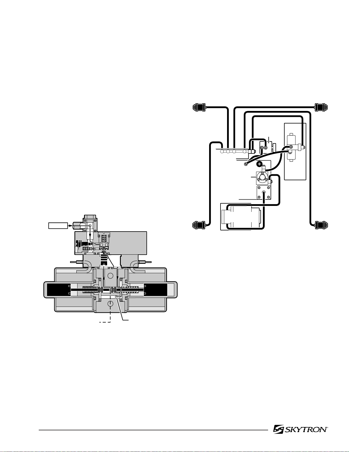
e. Elevation Cylinder Return Circuit
Page 13
A three-way (single check valve type) mini-valve
controls both the elevation and return circuits. The
elevation circuit operation within the mini-valve is
identical to the operation of the four-way valves
previously described (inlet pressure opens the
check valve allowing the oil to enter the cylinder). In
the return position, inlet pressure pushes the pilot
plunger up and opens the return check valve. See
figure 1-14. The open check valve allows a path for
the oil in the elevation cylinder to return to the
reservoir. When the pilot plunger valve is opened,
the continuing pump pressure opens the pressure
relief valve which provides a return oil path to the
reservoir.
The mini-valve used in the elevation circuit contains only one check valve (all four-way mini-valves
use two check valves). The check valve is used to
trap the oil in the elevation cylinder thereby supporting the table top. When the top is being lowered
the check valve is mechanically held open by the
pilot plunger through pump pressure.
3. Manually controlled emergency brake re-
lease.
4. Plumbing terminal, flexible hoses, copper
lines and "O" rings.
5. Portions of the electrical system.
BRAKE
EMERGENCY
BRAKE
RELEASE
PLUMBING
TERMINAL
PRESSURE
RELIEF
VALVE
BRAKE
MINI
VALVE
BRAKE
INLET
TO RESERVOIR THROUGH
PRESSURE RELIEF VALVE
RETURN TO
RESERVOIR
82205-114
Figure 1-14. Elevation Return Circuit
f. Brake System
The brake system consists of the following components: (figure 1-15)
1. Single action slave cylinders (4 each).
BRAKE
MOTOR/PUMP
ASSEMBLY
BRAKE
82205-115
Figure 1-15. Brake System Block Diagram
Each corner of the cast-iron table base has a
hydraulic brake cylinder. These single action cylinders are hydraulically connected in parallel to the
mini-valve and all four are activated together. It is
normal for one corner of the table to raise before the
others due to the weight distribution of the table.
An electronic timer in the relay box is activated
when any function on the pendant control is
pushed momentarily. The pump/motor and brake
system mini-valve are activated and the brake
cylinders are completely set. The electronic timer
runs for approx. 8-10 seconds.
The brakes are released by pushing the BRAKE
UNLOCK button momentarily. An electronic timer
in the relay box activates the brake function hydraulic mini-valve and pump/motor.
2. 3-way (single check valve type) mini-valve.

Page 14
When activated, the return hydraulic circuit operates similar to the elevation cylinder return circuit.
Return springs inside the single action brake cylinders retract the brake pads and provide the pressure to return the hydraulic oil back to the reservoir.
The electronic timer operates the return circuit for
approximately 8-10 seconds.
g. Emergency Brake Release
The emergency brake release is simply a manually
operated bypass valve connected in parallel to the
brake cylinders and the oil reservoir. See figure 1-
16. When the valve is opened (turned counterclockwise) a return circuit for the brake hydraulic
fluid is opened. The return springs force the pistons
up pushing the hydraulic oil back into the reservoir
and retracting the brake pads.
h. Flex/Reflex System
The Flex/Reflex system incorporates an additional
mini-valve which connects the Trendelenburg and
back section hydraulic systems in a series. When
FLEX is activated by the pendant control, the Flex/
Reflex mini-valve opens the oil pressure path to the
Reverse Trendelenburg piston. The return oil path
from the Trendelenburg piston is routed through
the back section cylinder to the mini-valve return
port. See figure 1-17
2
TREND.
3
REV.
TREND.
6
BACK
DOWN
7
BACK
UP
EMERGENCY
BRAKE
RELEASE
Figure 1-16.
NOTE
•The emergency brake release valve
must be tightened securely when not in
use.
•If the emergency brake release valve
has been operated, the UNLOCK button on the pendant control may have to
be pressed before brakes will lock again.
82205-116
PLUMBING
TERMINAL
MINI-
VALVES
2 6
3 7
2
7
FLEX/
REFLEX
Figure 1-17. Flex/Reflex System
82205-117
If the emergency brake release valve is open, the
brakes will release slowly- depending on how far
open the valve is, this could take anywhere from a
few minutes to several hours.
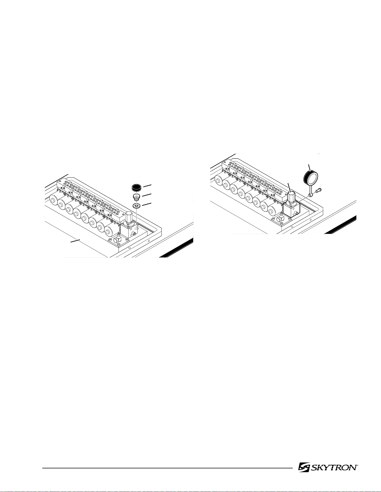
82205-11
FILLER CAP
FITTING
GASKET
OIL TANK
RESERVOIR
1-3. Hydraulic Adjustments
Page 15
a. Fluid Level.
The fluid level should be approximately 1/2" below
the filler hole or gasket surface. If additional fluid is
needed, remove the filler vent cap with a phillips
screwdriver and add fluid through this opening
using a funnel. See figure 1-18.
NOTE
The elevation cylinder should be completely down, the brakes released and
all the other control functions in their
neutral position when checking oil level.
c. Pressure Relief Valve
The pressure relief valve is adjusted by turning the
adjustment nut until the desired pressure is reached.
To adjust:
1. Remove the plumbing bolt securing the
brake system line to the pressure relief valve and
attach a hydraulic pressure gauge to the main oil
galley using a long 6mm plumbing bolt. See figure
1-19.
PRESSURE
GAUGE
PRESSURE
RELIEF
VALVE
PLUMBING
BOLT
Figure 1-18.
The type of oil that should be used is Mobil DTE #25
or equivalent. This is a very high quality hydraulic
oil. The table requires approximately two quarts of
oil to operate properly. Excercise caution when
determining equivalance to avoid damage to the
hydraulic system.
b. Bleeding The Hydraulic System
To purge the air from the hydraulic system, operate
each function back and forth at least two or three
times.
NOTE
Whenever a hydraulic line or component is replaced, bleed the air out of the
lines using the pump pressure by activating the function before making the
final connection. Then operate the function until it stalls in both directions.
82205-119
Figure 1-19.
2. Raise the table top until the piston reaches
the end of its stroke and stalls. Observe reading on
pressure gauge and turn the adjustment nut (clockwise to increase oil pressure, counterclockwise to
decrease) until desired reading is obtained. Pressure should be 8MPA (80KG/CM2 -1138 PSI). An
erratic reading and/or inability to adjust to the
recommended setting may indicate the need for
replacement of the pressure relief valve.
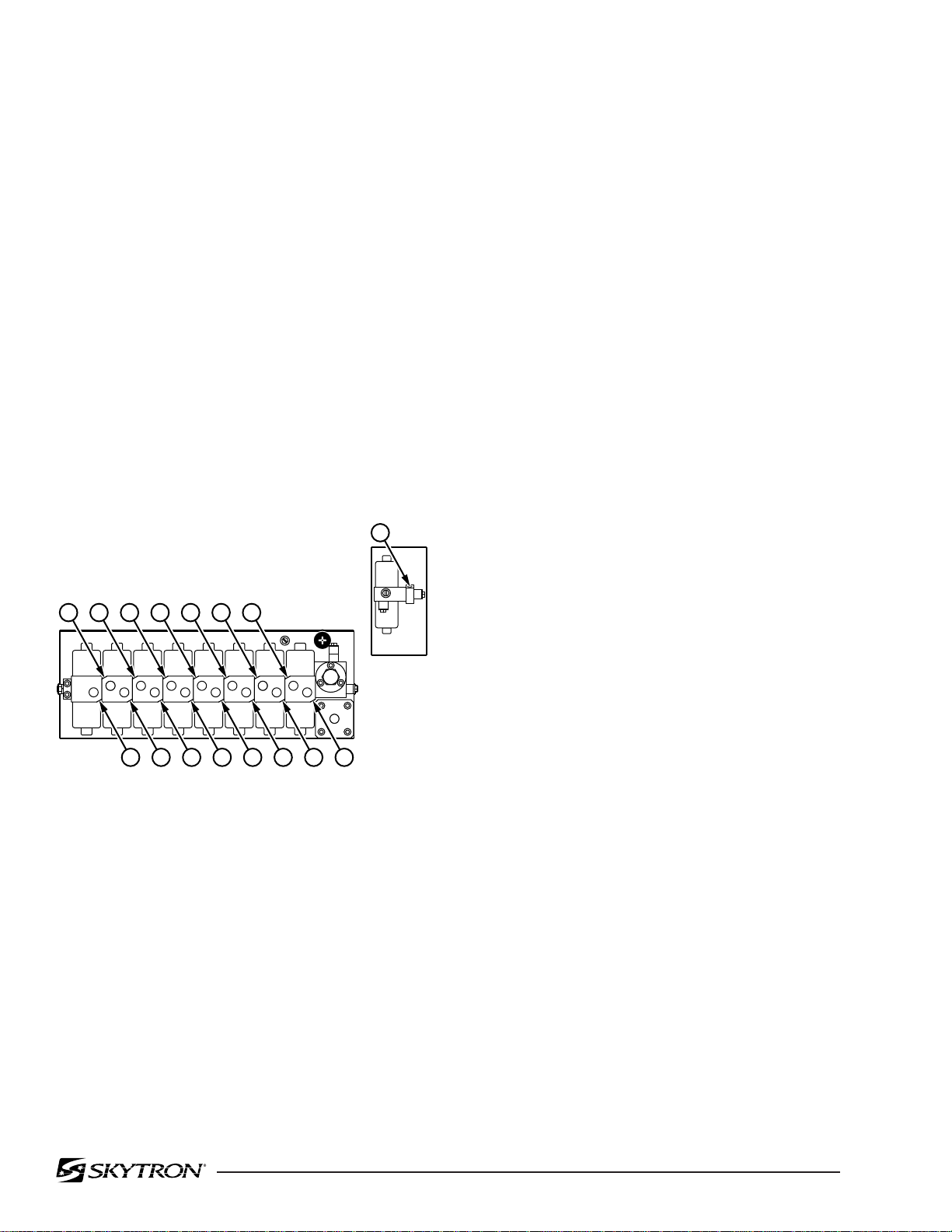
Page 16
d. Speed Controls
The speed controls restrict the volume of oil returning back to the reservoir thereby controlling the
speed of each control function.
All four-way mini-valves, have two speed controls
located in the ends of each valve body. All threeway mini-valves have only one speed control.
One speed control adjusts one direction of a
particular function and the opposite speed control
adjusts the other direction. They are adjustable by
using a small straight blade screwdriver and
turning the adjustment screw clockwise to decrease the speed and counterclockwise to
increase the speed. See figure 1-20.
1. TABLE DOWN
2. TRENDELENBURG
3. REVERSE TREND.
4. TILT RIGHT
5. TILT LEFT
6. REFLEX
7. FLEX
8. BACK UP
2 4 6 8 10 12 14
MINI-
VALVES
4
2
1
3
ELEV SLIDE
2
5
9. BACK DOWN
10. FOOT DOWN
11. FOOT UP
12. KIDNEY UP
13. KIDNEY DOWN
14. SLIDE FOOT
15. SLIDE HEAD
16. BRAKES
6
8
7
7
LEGBACKFLEXTILTTREND
9
10
KIDNEY
16
BRAKE
12
11
13
Any control function should move in either direction at the same rate. If the rate of a certain function
is too slow, open the speed control slightly and
recheck. Use the second hand on a watch and time
a particular function. Match that time in the opposite direction by opening or closing the speed
control. Approximate operating times are as follows:
Lateral Tilt 7 seconds
Leg Up 25 seconds
Leg Down 15 seconds
Kidney Lift 7 seconds
Slide 29 seconds
A pressure gauge should be used to set the speed
of the back section, Trendelenburg and flex control
functions.
To adjust:
1. Attach the pressure gauge onto the main oil
galley as shown in figure 1-19.
2. The gauge should read the following values
when operating the various control functions in
either direction. Turn the speed controls until
desired values are obtained.
1
3 5 7 9 11 13 15
Figure 1-20.
82205-120
2
Back Section Up 65KG/CM
-925PSI
Dn 65KG/CM2 -925PSI
Trendelenburg Up 65KG/CM2 -925PSI
Dn 65KG/CM2 -925PSI
Flex 70KG/CM2 -995PSI
Reflex 70KG/CM2 -995PSI
NOTE
When adjusting Flex/Reflex speed controls, set Reflex last.
Elevation - There is not a speed adjustment for
raising the table. The speed control will only affect
the rate of descent and it should equal the rate of
elevation.
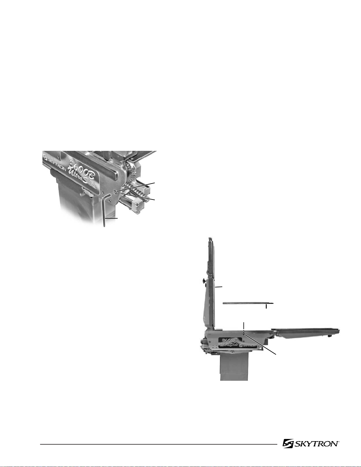
SECTION II MECHANICAL TABLE ADJUSTMENTS
82205-202
BACK SECTION
SET SCREW
SEAT SECTION TOP
BACK SECTION
CYLINDER
ECCENTRIC CAM
2-1. Back Section Gear Mesh Adjustment
The gear mesh is adjusted by the use of an eccentric cam. This cam moves the gear teeth closer
together to eliminate gear lash. This adjustment
arrangement compensates for any wear between
the gears that might occur.
Page 17
a. Back Section
Position the back section all the way up until it
stalls. Both sides of the back section should stop
moving at the same time and should not show any
signs of twisting.
To adjust:
Loosen the cam locking allen set screw. Use an
allen wrench to rotate the eccentric cam. See
figure 2-1. Tighten the locking set screw when
adjustment is complete.
ECCENTRIC
CAM
SET SCREW
ALLEN
WRENCH
82205-201
Figure 2-1. Eccentric Cam Adjustment
Any twisting or flexing of the back section as it
approaches the stalled position indicates that one
of the cylinders is not reaching its fully extended
position at the same time as the other. This
condition would require an adjustment.
To adjust:
Remove the seat section top for access to the cam
locking set screws and loosen the set screws. Use
an allen wrench to turn the cylinder eccentric cams
as required to shift either cylinder fore or aft as
needed so no twisting or flexing of the back section
is observed when it is stalled in the full up position.
See figure 2-2. Tighten the set screws and replace
the seat section top when the adjustment is completed.
2-2. Hydraulic Cylinder Adjustment
The hydraulic cylinder rams that control both the
back and leg sections must move together so that
these sections are not twisted when operated. This
is accomplished by the use of eccentric cams that
move the cylinder bodies fore and aft to adjust their
effective stroke.
NOTE
Adjust gear mesh before adjusting eccentric cams for the back section.
Figure 2-2. Back Section Adjustment

Page 18
b. Leg Section
Position the leg section all the way up. Both sides
of the leg section should stop moving at the same
time and should not show any signs of twisting.
Any twisting or flexing of the leg section as it
approaches the stalled position indicates that one
of the cylinders is not reaching its fully extended
position at the same time as the other and an
adjustment is required.
To adjust:
BALL JOINT
COLLAR
ALLEN BOLT
TRENDELENBURG
CYLINDER
82106-101
Loosen the cam locking set screws located inside
the table side frames. See figure 2-3. Use an allen
wrench to turn the cylinder eccentric cams as
required to shift either cylinder fore or aft as needed
so no twisting or flexing of the leg section is
observed when it is stalled in the above horizontal
position. Tighten set screws when proper adjustment is achieved.
LEG SECTION
LEG SECTION CYLINDER
ECCENTRIC CAM
82205-203
Figure 2-3. Leg Section Adjustment
c. Trendelenburg Cylinder Ball Joint
Inspect the Trendelenburg ball joint on a periodic
basis. Check for play of table top by sliding the table
top to each extremity and applying a load. Observe
for any movement in the joint. No visible play is
permitted. If movement is observed inspect the
tightness of the ball joint collar and the locking allen
bolt. See figure 2-4. Also inspect the ball socket for
signs of wear or metal particulate. Lubricate periodically using a white lithium based grease.
Figure 2-4. Trendelenburg Cylinder
2-3. Head Section Adjustment
The head section can be adjusted to eliminate any
flexing throughout it's range of travel.
To adjust:
Place the head section in level position and remove
the top. See figure 2-5. Loosen but do not remove
the allen bolts securing the bearing block to the
frame. Loosen the allen bolt in the top of the frame
and turn the set screw as required to achieve
proper adjustment. One or both of the blocks may
require adjustment to achieve proper alignment.
Tighten all allen bolts when adjustment is complete. Test the head section throughout its range of
travel. Re-adjust as needed. Replace top section
when proper adjustment is achieved.
ADJUSTMENT
ALLEN
BOLT
SET SCREW
ALLEN
BOLTS
82205-205
Figure 2-5. Head Section Adjustment

Page 19
2-4. Slide Roller Adjustment
The pivot pins on the slide rollers are eccentric
cams. The rollers can be adjusted if required to
maintain proper top slide operation.
To adjust:
Remove the Seat section top, the hose cover and
the right and left lateral tilt frame covers for access
to the top rollers.
1. Align the table top so the rollers to be
adjusted are contacting the slide bars.
2. Loosen the adjustment cam set screw and
adjust the roller using an 8mm Allen wrench. See
figure 2-6. To avoid any possible binding in the
slide mechanism, adjust the roller on the opposite
side of the table in the same manner (cam turned
toward same end of table on each side).
3. Lubricate rollers and slides with white lithium
based grease.
2-5. Side Rails
Inspect each of the side rail sections. Make sure
that all retaining hardware is tight. Inspect the
gravity stops. Make sure that each gravity stop
moves freely. Clean, lubricate or replace as necessary. See figure 2-7.
SIDE
RAIL
GRAVITY
STOP
82106-102
Figure 2-7.
4. Adjust rollers so top slides smoothly with no
up or down movement of the table top.
5. When adjustment is complete, tighten set
screws, replace covers and top section.
SLIDE
ROLLER
82205-206
SET SCREW
8mm
ALLEN
WRENCH
Figure 2-6.
2-6. Casters
Clean and lubricate each of the casters. Remove
any debris caught in the casters and old grease.
Lubricate using a grease gun and conventional
wheel bearing grease. The casters should rotate
freely providing a smooth movement of the table
during positioning. Replace worn or defective casters as required.

Page 20

3-1. Precautions
SECTION III HYDRAULIC TROUBLESHOOTING
Page 21
Before attempting to troubleshoot any hydraulic
problem on the table, please read through the precautions and notes below.
CAUTION
When disconnecting any of the hydraulic lines, fittings, joints, hoses, etc., for
the following control functions, be sure
these table surfaces are in their down
position or completely supported.
Elevation
Back Section
Leg Section
Kidney Lift
When working on the Trendelenburg
or lateral tilt hydraulic circuits, be sure
to support the table top. When working
on the brake system make sure the
brakes are completely retracted.
Once the problem has been determined, concentrate on that particular hydraulic circuit or control
function.
Listed below are the hydraulic components that
are common with all hydraulic circuits. If there is a
problem with any of them, it could affect all control
functions.
1. Motor/Pump Assembly
2. Reservoir
3. Pressure Relief Valve
4. Certain Oil Lines and Galleys
If there was a problem in the following components,
only one control function would normally be affected.
1. Mini-Valve
2. Slave Cylinder
3. Oil Lines
NOTE
WARNING
Failure to follow these precautions may
result in an uncontrolled oil spray and
damage to the table or personal injury.
3-2. Troubleshooting Notes
When troubleshooting a table malfunction, first
determine the following:
1. Does the problem affect all control functions?
2. Does the problem affect only one control
function?
3. If the problem affects one control function is
it in both directions?
4. Is the problem intermittent?
Whenever a hydraulic line or component is replaced, bleed the air out of the
lines using the pump pressure before
making the final connection. After all
connections are tight, cycle the control
function back and forth two or three
times to purge the remaining air from
the system.
CAUTION
When installing new "O" rings use hydraulic oil or white lithium grease to
thoroughly lubricate the "O" rings and
cylinder. Keep everything clean.
Each complete oil circuit is shown on the following
pages. When troubleshooting a particular function,
refer to the appropriate oil circuit diagram and the
list of possible problems.
5. Is the problem no movement of a table
surface or does the table surface lose position?
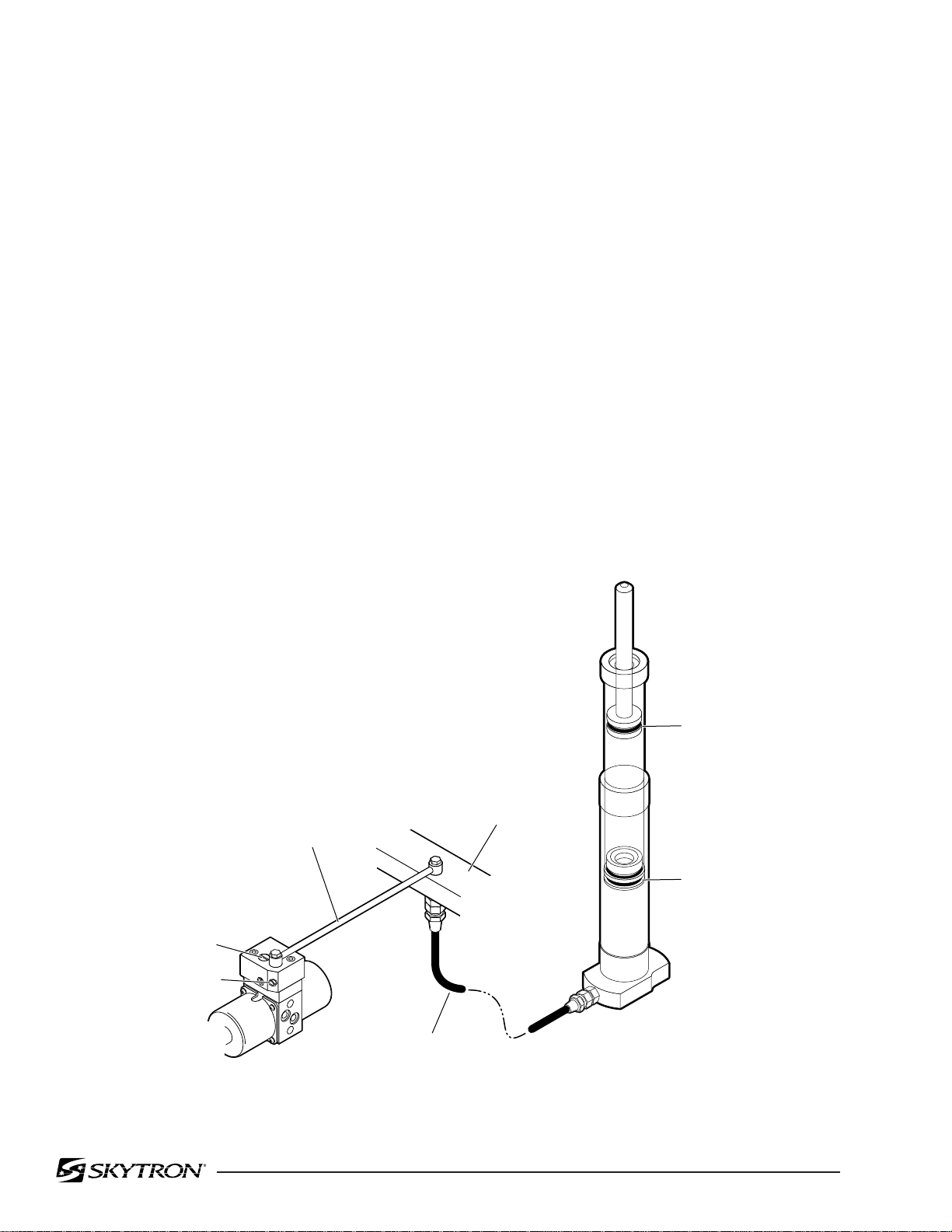
Page 22
3-3. ELEVATION DIAGNOSIS CHART
Problem
Table will not elevate properly
Table will not descend properly
Table loses elevation
Reason
Pressure Relief Valve Not Set Properly
Low on Oil
Spool Valve Not Centered
Defective Pump
Defective Mini-Valve
Defective Solenoid or Wiring
Defective Relay Box or Pendant Control
Leaking Cylinder Hose
Uneven Weight Distribution
Incorrect Speed Adjustment
Defective Check Valve
Spool Valve Not Centered
Galled Slider Assembly
Defective Solenoid or Wiring
Defective Relay Box or Pendant Control
Uneven Weight Distribution
Defective Check Valve
Leaking Mini-Valve
Loose Fittings, Joints, Hoses
Leaking "O" Ring Inside Cylinder
CHECK VALVE
SPEED CONTROL
MINIVALVE
MAIN PLUMING
COPPER
LINE
FLEXIBLE
HOSE
TERMINAL
Figure 3-1. Elevation Circuit
PRIMARY
PISTON O-RING
SECONDARY
PISTON O-RING
82205-301
 Loading...