


SURGICAL TABLE
PARTS CATALOG
REV 9/07
3501B EZ SLIDE


INTRODUCTION
This manual contains the exploded views and replacement parts lists for the service-
able components of the SKYTRON Model 3501B EZ SLIDE Surgical Table.
Each serviceable part in these exploded views is identified by a reference number.
Use this number to locate necessary part information in the parts list adjacent to the exploded view.
Always use the complete SKYTRON part number and description when ordering
replacement parts.
Always use the complete table serial number (S.N.) when ordering replacement
parts.
Special Tools and Maintenance Items listed on page 40.
Page 1
Abbreviations
As Required ........................................... A/R
Optional ................................................... opt
Serial Number ....................................... S.N.
Not Shown............................................... NS
Although current at the time of publication, SKYTRON's policy of continuous development makes this
manual subject to change without notice.

Page 2

3501B EZ SLIDE EQUIPMENT LABELS
Page 3
15
16
14
13
12
11
10
1
2
3
4
5
6
7
4
8
9
D6-032-47
1
USE HEAD SECTION AS FOOT EXTENSION
ONLY - WHEN REVERSING PATIENT ON TABLE
REFER TO OPERATOR MANUAL.
WARNING
D6-017-05
4
5
D6-017-28
7
D6-065-24
DANGER - E
XPLOS
ION
H
AZARD.
DO
11
T
HE
PRESENCE OF
DANGER - RISQUE
EMPLOYER EN
INFLAMMABLES
FLA
D'E
PRE
MMAB
LE
ANAE
XPL
OSION. NE
SENCE
D'A
NOT USE IN
STHETICS
NESTHESIQUES
PAS
D6-032-46
2
DO NOT SIT ON END OF LEG SECTION(S) AS LOADS
IN EXCESS OF 140 LBS, MAY CAUSE INSTABILITY
THAT COULD CAUSE THE TABLE TO BE TIPPED OVER.
WARNING
D3-035-60 right D3-035-61 left
D6-017-29
8
D6-065-23
12
POSSIBL
IF USED IN THE PRESENCE OF
FLAMMABLE ANESTHETICS.
E E
XPLOSION
DANGER
9
HAZARD
L1-010-00
NO PART NUMBER
3
D6-035-38
6
D6-065-22
13
Table Capacity:
Lift
7
00 lbs.
Articulate 6
Manual for Limitations.
00 lbs.
See Operators
D6-011-34
THIS PRODUCT COMPLIES WITH RADIATION PERFORMANCE STANDARD 21 CFR
AT THE TIME OF MANUFACTURE
10
Manufactured:
Model No.
14
D6-034-21
15
D6-065-21
Grounding
reliability can only be a
the equip
ment is connected t
receptacle mar
ked "Hospit
al Only"
chiev
o an
or "Hosp
ed w
equivalent
ital Grade"
hen
16
D6-067-27
TWIST TO LOCK OR RELEASE PLUG

Page 4
1. Head Section Assembly ...................................... Page 8. 2. Back Section Assembly ...................................... Page 10.
3. Leg Section Assembly ...................................... Page 12. 4. Side Frame Assemblies ...................................... Page 14.
Page 5
5. Back & Leg Section Cylinder Assemblies ......... Page 16. 6. Kidney Lift Assembly........................................... Page 18.
7. Slide Assembly ................................................. Page 20. 8. Lateral Tilt Assembly ........................................... Page 22.

Page 6
9. Trendelenburg Assembly .................................. Page 24. 10. Elevation Assembly ...........................................Page 28.
11. Hydraulic Components ................................... Page 30. 12. Electro Mini-Valve Assembly............................. Page 34.

Page 7
13. Pump & Electrical Components ...................... Page 36. 14. Base & Electrical Components ......................... Page 38.

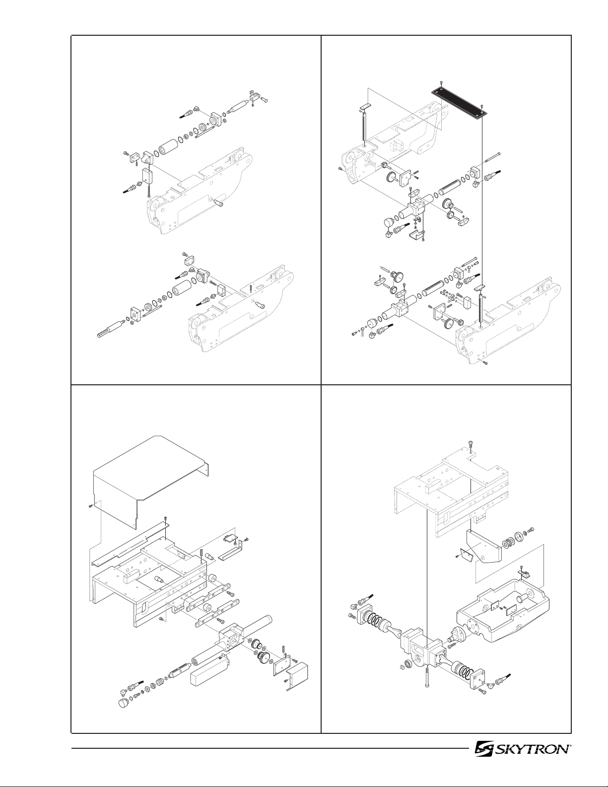
Page 8
1. HEAD SECTION ASSEMBLY
3
1
2
4
31
30
17
27
29
18
26
28
24
25
23
22
17
21
7
9
8
10
11
5
6
12
13
14
16
15
19
3501B.0711.01
18
20
17

Page 9
1. HEAD SECTION ASSEMBLY
Item Part No. Description Qty.
1-010-55-P PAD SET, regular ......................................................................................................... opt.
1-010-55-S PAD SET, soft ..............................................................................................................opt.
D3-067-00 COMPLETE HEAD SECTION .......................................................................................1
1 D3-010-19 SCREW, phillips head ................................................................................................... 4
2 D3-067-01 TOP, head section ......................................................................................................... 1
3 D3-010-18-H VELCRO, hook ............................................................................................................A/R
4 5-010-01-8 BUSHING, x-ray top ...................................................................................................... 2
5 D4-010-14 O-RING, P-12 ................................................................................................................2
6 D3-067-02 SHAFT, extension, head section (roll pin) .....................................................................2
7 D6-050-33 PIN, roll, M5 x 20 ...........................................................................................................2
8 D3-032-80 GEAR, trunnion, right .................................................................................................... 1
D3-032-81 GEAR, trunnion, left ......................................................................................................1
9 D6-010-41-1 SCREW, set, M8 x 15 (plated) ....................................................................................... 2
10 D6-010-38-1 BOLT, allen, M6 x 15 (plated) ........................................................................................ 2
11 D6-010-40-1 WASHER, lock, M6 (plated) ..........................................................................................2
12 D3-067-03 FRAME, head section ................................................................................................... 1
13 D3-034-22 BUSHING, head section ................................................................................................2
14 D6-010-53-1 BOLT, allen, M8 x 20 (plated) ........................................................................................ 2
15 D3-032-34 STUD, side rail mount, M8 x 45 .....................................................................................2
16 D3-067-04 RAIL, side, head section ...............................................................................................2
17 D3-032-35 STUD, side rail mount, M8 x 40 .....................................................................................4
18 D3-010-01 COLLAR, side rail ..........................................................................................................6
19 D6-010-38 BOLT, allen, M6 x 15......................................................................................................4
20 D6-010-40 WASHER, lock, M6........................................................................................................4
21 D3-067-05 PLUNGER, release, right ..............................................................................................1
D3-067-06 PLUNGER, release, left.................................................................................................1
22 D6-010-13 NUT, hex, M8 .................................................................................................................6
23 D6-010-09 WASHER, lock, M8........................................................................................................6
24 D3-032-33 RAIL, accessory ............................................................................................................ 1
25 D3-067-07 SPRING, release ...........................................................................................................2
26 D3-032-40 BLOCK, bearing ............................................................................................................ 2
27 D6-010-11 SCREW, set, M5 x 8 (plated) ......................................................................................... 2
28 D6-010-13-1 NUT, hex, M8 (plated) .................................................................................................... 2
29 D3-010-24 RELEASE BAR, head section .......................................................................................1
30 D6-010-09 WASHER, lock, M8........................................................................................................2
31 D6-010-08 NUT, acorn, M8 .............................................................................................................2
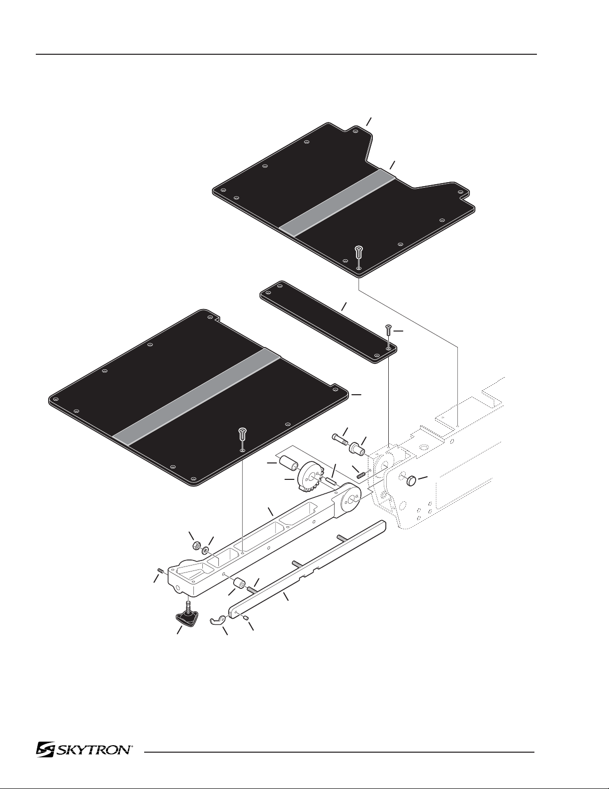
Page 10
2. BACK SECTION ASSEMBLY
1
2
3
21
22
20
19
18
16
15
17
9
12
10
14
11
4
5
6
7
8
13
3501B.0711.02

Page 11
2. BACK SECTION ASSEMBLY
Item Part No. Description Qty.
1-010-55-P PAD SET, regular ......................................................................................................... opt.
1-010-55-S PAD SET, soft ..............................................................................................................opt.
1 D3-035-37 TOP, seat section ........................................................................................................... 1
2 D3-010-18-H VELCRO, hook ............................................................................................................A/R
3 D3-035-01 TOP, seat section, small ................................................................................................1
4 D3-010-19 SCREW, phillips .......................................................................................................... A/R
5 D3-035-45 TOP, back section ..........................................................................................................1
6 D6-032-28 BOLT, allen ....................................................................................................................2
7 D3-035-34 CAP, back section ..........................................................................................................1
8 D6-010-50 SCREW, set M6 x 15 .....................................................................................................4
9 D3-032-21 BUSHING, back section ................................................................................................2
10 D3-035-41 GEAR, spur, back section .............................................................................................2
11 D6-032-30 PIN, spur gear ............................................................................................................... 4
12 D3-035-46 FRAME, back section, right ...........................................................................................1
D3-035-47 FRAME, back section, left .............................................................................................1
13 D3-032-36 CAP, back section, axis ................................................................................................. 2
14 D3-035-48 SIDE RAIL, back section, right ......................................................................................1
D3-035-49 SIDE RAIL, back section, left ........................................................................................ 1
15 D3-010-41 PIN, rail stop .................................................................................................................. 2
16 D3-010-43 RAIL STOP, large .......................................................................................................... 2
17 D3-032-34 STUD, side rail mount, M8 x 45 .....................................................................................6
18 D3-010-01 COLLAR, side rail ..........................................................................................................6
19 D6-010-09-1 WASHER, lock, M8 (plated) ..........................................................................................6
20 D6-010-13-1 NUT, M8 (plated) ........................................................................................................... 6
21 D6-060-38 SCREW, set, M5 x 10 ....................................................................................................2
22 D3-010-17 KNOB, retaining ............................................................................................................. 2

Page 12
3. LEG SECTION ASSEMBLY
1
2
3
4
17
19
18
16
15
14
23
21
20
13
5
6
12
10
11
10
7
8
9
25
26
24
22
3501B.0711.03

Page 13
3. LEG SECTION ASSEMBLY
Item Part No. Description Qty.
1-010-55-P PAD SET, regular ......................................................................................................... opt.
1-010-55-S PAD SET, soft ..............................................................................................................opt.
1 D3-035-50 TOP, foot / leg section .................................................................................................... 1
2 D3-010-18-H VELCRO, hook ............................................................................................................A/R
3 D3-010-19 SCREW, phillips ........................................................................................................... 10
4 D6-031-01 KNOB, locking ............................................................................................................... 2
5 D3-035-51 FRAME, foot / leg section, right .....................................................................................1
D3-035-52 FRAME, foot / leg section, left .......................................................................................1
6 D3-010-43 STOP, rail, large .............................................................................................................2
7 D3-010-41 PIN, rail stop .................................................................................................................. 2
8 D3-035-53 RAIL, side, foot / leg section, right .................................................................................1
D3-035-54 RAIL, side, foot / leg section, left ...................................................................................1
9 D3-032-35 STUD, side rail mount, M8 x 40 .....................................................................................2
10 D3-032-34 STUD, side rail mount, M8 x 45 .....................................................................................4
11 D3-010-01 COLLAR, side rail ..........................................................................................................6
12 D6-010-09-1 WASHER, lock, M8 (plated) ..........................................................................................6
13 D6-010-13-1 NUT, M8 (plated) ........................................................................................................... 6
14 D3-032-51 SPRING, back section, right ..........................................................................................1
D3-032-51-1 SPRING, back section, left ............................................................................................1
15 D6-010-65-1 BOLT, allen, M5 x 35 (plated) ........................................................................................2
16 D6-032-37 PIN, roll, M4 x 30 ...........................................................................................................2
17 D6-010-87 SCREW, set, M6 x 20 ....................................................................................................2
18 D3-034-31 LEVER, axis, foot / leg section, right .............................................................................1
D3-034-32 LEVER, axis, foot / leg section, left ...............................................................................1
19 D3-030-05 AXIS, foot / leg section ..................................................................................................2
20 D3-035-55 LEVER, release, right .................................................................................................... 1
D3-035-56 LEVER, release, left ......................................................................................................1
21 D6-067-01 SCREW, phillips, button head, M3 x 8 ........................................................................... 2
22 D6-010-79 SCREW, phillips, button head, M3 x 5 ........................................................................... 2
23 D3-035-57 HINGE ........................................................................................................................... 2
24 D3-034-46 STOP, rubber .................................................................................................................2
25 D6-010-76 NUT, hex, M5 .................................................................................................................2
26 D6-010-83 BOLT, allen, M5 x 30 ......................................................................................................2

Page 14
4. SIDE FRAME ASSEMBLIES
6
5
7
8
4
2
1
3
9
11
15
17
18
10
14
12
13
16
19
22
32
31
20
30
21
29
23
24
26
25
27
28
3501B.0711.04

Page 15
4. SIDE FRAME ASSEMBLIES
Item Part No. Description Qty.
1 D6-060-07 BOLT, allen, M4 x 8 ........................................................................................................2
2 D6-035-19 WASHER, flat, M4 .........................................................................................................2
3 D5-036-07 MICRO-SWITCH ........................................................................................................... 1
4 D5-036-08 BRACKET, micro-switch mounting ................................................................................1
5 D3-035-08 FRAME, side, left...........................................................................................................1
6 D6-066-18 SCREW, countersunk phillips, M4 x 15 .........................................................................4
7 D5-032-17 MICRO-SWITCH ........................................................................................................... 2
8 D3-035-20 BRACKET, micro-switch mounting, left .......................................................................... 1
D3-035-21 BRACKET, micro-switch mounting, right .......................................................................1
9 D3-035-58 COVER, micro-switch ....................................................................................................1
10 D6-035-04 SCREW, phillips, M4 x 6 ................................................................................................ 2
11 D3-035-20 BRACKET, slide bar, left ................................................................................................ 1
12 D6-010-53 BOLT, allen, M8 x 20 ......................................................................................................8
13 D3-035-22 ACTUATOR, slide, micro-switch .................................................................................... 1
14 D6-010-28-1 BOLT, allen, M5 x 6 ........................................................................................................3
15 D3-035-19 BAR, slide ...................................................................................................................... 2
16 D6-010-33 BOLT, allen, M8 x 25 ......................................................................................................8
17 D3-035-13 COVER, hose, left .........................................................................................................1
D3-035-14 COVER, hose, right .......................................................................................................1
18 D6-043-10 SCREW, phillips, M4 x 8 ................................................................................................ 6
19 D3-035-59 BRACKET, slide bar, right .............................................................................................. 1
20 D6-010-13-1 NUT, M8 (plated) ........................................................................................................... 6
21 D6-010-09-1 WASHER, lock, M8 (plated) ..........................................................................................6
22 D3-035-07 FRAME, side, right ........................................................................................................ 1
23 D3-035-60 NAMEPLATE, decal, 3501B, right .................................................................................1
D3-035-61 NAMEPLATE, decal, 3501B, left ................................................................................... 1
24 D3-010-43 STOP, rail (large) ...........................................................................................................2
25 D3-010-41 PIN, rail stop .................................................................................................................. 2
26 D3-032-34 STUD, side rail mount, M8 x 45 .....................................................................................6
27 D3-035-04 SIDE RAIL, seat section, right .......................................................................................1
D3-035-05 SIDE RAIL, seat section, left .........................................................................................1
28 D3-010-01 COLLAR, side rail ..........................................................................................................6
29 D3-035-30 AXIS, eccentric cam ......................................................................................................2
30 D6-035-05 SCREW, set, M6 x 8 ......................................................................................................2
31 D3-035-29 ROLLER, support .......................................................................................................... 2
32 D3-035-28 SPACER, nylon .............................................................................................................. 2

Page 16
5. BACK & LEG SECTION CYLINDER ASSEMBLIES
1
30
29
2
25
26
27
31
33
30
32
34
12
35
7
6
28
8
9
11
10
8
3
4
5
8
36
37
38
30
13
29
14
41
40
15
39
18
16
19
20
21
17
20
22
30
29
31
23
32
30
20
24
34
42
43
44
38
3501B.0711.05

Page 17
5. BACK & LEG SECTION CYLINDER ASSEMBLIES
Item Part No. Description Qty.
D4-035-06-1 CYLINDER ASSEMBLY, leg section, left .......................................................................1
D4-035-06-2 CYLINDER ASSEMBLY, leg section, right ..................................................................... 1
1 ----- •RAM .............................................................................................................................1
2 D4-036-67 •PENTASEAL, PS-22A ..................................................................................................1
3 D6-010-55 •NUT, M8 ....................................................................................................................... 4
4 ----- •HEAD CAP ................................................................................................................... 1
5 D4-035-07 •STUD ........................................................................................................................... 4
6 ----- •PISTON ........................................................................................................................1
7 D4-010-02 •O-RING, P-14 ............................................................................................................... 1
8 D4-010-54 •O-RING, P-34 ............................................................................................................... 3
9 D6-010-42 •WASHER, lock, M10 ....................................................................................................1
10 D6-010-43 •NUT, M10 .....................................................................................................................1
11 ----- •CYLINDER ................................................................................................................... 1
12 ----- •TAIL CAP ......................................................................................................................1
D4-035-04-1 CYLINDER ASSEMBLY, back section, left .................................................................... 1
D4-035-04-2 CYLINDER ASSEMBLY, back section, right ..................................................................1
13 ----- •RAM ............................................................................................................................. 1
14 D4-036-67 •PENTASEAL, PS-22A ..................................................................................................1
15 D6-010-55 •NUT, M8 ....................................................................................................................... 4
16 ----- •HEAD CAP ................................................................................................................... 1
17 D4-035-05 •STUD ........................................................................................................................... 4
18 D4-010-02 •O-RING, P-14 ...............................................................................................................1
19 ----- •PISTON ........................................................................................................................1
20 D4-010-54 •O-RING, P34 ................................................................................................................3
21 D6-010-42 •WASHER, lock, M10 .................................................................................................... 1
22 D6-010-43 •NUT, M10 .....................................................................................................................1
23 ----- •CYLINDER ................................................................................................................... 1
24 ----- •TAIL CAP ......................................................................................................................1
25 D6-036-08 CIRCLIP ........................................................................................................................2
26 D6-036-07 CLEVIS ..........................................................................................................................2
27 D6-036-06 PIN, clevis......................................................................................................................2
28 D6-010-34 SCREW, set, M6 x 6 ......................................................................................................2
29 D4-010-29 FITTING, hydraulic, 90° elbow .................................................................................... A/R
30 ----- HOSE, flexible (specify function) .................................................................................A/R
31 D6-010-53 BOLT, allen, M8 x 20 ......................................................................................................4
32 D4-036-05 PLATE, cylinder mounting, left ...................................................................................... 1
D4-036-06 PLATE, cylinder mounting, right .................................................................................... 1
33 D6-010-87 SCREW, set, M6 x 20 ....................................................................................................2
34 D4-031-06 FITTING, flexible hose................................................................................................. A/R
35 D4-010-01 O-RING, P8 ...................................................................................................................1
36 D4-035-15-2 BLOCK, plumbing, left ...................................................................................................1
D4-035-15-1 BLOCK, plumbing, right .................................................................................................1
37 D6-032-09 BOLT, allen, M5 x 50 ......................................................................................................2
38 D6-036-09 AXIS, eccentric cam ......................................................................................................4
39 D6-010-10-3 BOLT, allen, M4 x 10 ......................................................................................................4
40 D5-036-20 BRACKET, micro-switch mounting, left .......................................................................... 1
D5-036-19 BRACKET, micro-switch mounting, right .......................................................................1
41 D5-036-18 MICRO-SWITCH ........................................................................................................... 2
42 D6-036-10 BOLT, allen, M6 x 40 ......................................................................................................2
43 D4-035-52 BLOCK, plumbing .......................................................................................................... 1
44 D6-010-91 SCREW, set, M6 x 25 ....................................................................................................2

Page 18
44
27
26
6. KIDNEY LIFT ASSEMBLY
28
32
29
33
24
25
24
1
2
3
3
4
45
46
23
21
18
22
12
20
30
37
19
11
35
31
34
5
6
36
17
18
42
15
10
40
41
16
33
3
38,39
43
31
15
7
15
14
32
36
8
34
35
37
9
6
13
48
26
27
28
29
49
47
34
30
35
3501B.0711.06
44

Page 19
6. KIDNEY LIFT ASSEMBLY
Item Part No. Description Qty.
D4-035-09-1 CYLINDER ASSEMBLY, kidney lift, left .........................................................................1
1 D6-035-01 •BOLT, allen, M6 X 100 ..................................................................................................4
2 ----- •END CAP, left cylinder ..................................................................................................1
3 D4-010-57 •O-RING, P-21 ............................................................................................................... 3
4 D4-035-09-4 •PISTON, kidney lift .......................................................................................................1
5 D6-010-70 •BOLT, allen, M5 x 10 ....................................................................................................4
6 D4-035-10 •PILLOW BLOCK ........................................................................................................... 2
7 D4-035-11 •GEAR ........................................................................................................................... 1
8 D4-035-11-1 •SHAFT .........................................................................................................................1
9 D6-010-34 •SCREW, set, M6 x 6..................................................................................................... 2
10 D4-035-09-5 •CYLINDER, kidney lift w/end caps, left ...................................................................... 1
D4-035-09-6 •CYLINDER, kidney lift w/end caps, right .................................................................... 1
11 D4-010-12 •O-RING, P-24 .............................................................................................................. 1
12 ----- •HEAD CAP, left cylinder .............................................................................................. 1
D4-035-09-2 CYLINDER ASSEMBLY, kidney lift, right ...................................................................... 1
13 D6-035-01 •BOLT, allen, M6 x 100 ................................................................................................. 4
14 ----- •END CAP, right cylinder .............................................................................................. 1
15 D4-010-57 •O-RING, P-21 .............................................................................................................. 3
16 D4-035-09-4 •PISTON, kidney lift ...................................................................................................... 1
17 D6-010-70 •BOLT, allen, M5 x 10 ................................................................................................... 4
18 D4-035-10 •PILLOW BLOCK .......................................................................................................... 2
19 D4-035-11 •GEAR .......................................................................................................................... 1
20 D4-035-11-1 •SHAFT ......................................................................................................................... 1
21 D6-010-34 •SCREW, set, M6 x 6 .................................................................................................... 2
22 D4-010-12 •O-RING, P-24 .............................................................................................................. 1
23 ----- •HEAD CAP, right cylinder ...........................................................................................1
24 D5-035-42-1 SCREW, round head phillips, M5 x 10 ........................................................................ 4
25 D5-035-42 TOP, kidney lift .............................................................................................................. 1
26 D3-032-39-1 PIVOT, kidney lift .......................................................................................................... 2
27 D6-031-24 PIN, roll, M5 x 15 .......................................................................................................... 2
28 D3-032-52 SHAFT, kidney lift ......................................................................................................... 2
29 D4-035-14 GEAR ........................................................................................................................... 2
30 D4-035-13 GEAR ........................................................................................................................... 2
31 D3-035-62 COVER, gear................................................................................................................ 2
32 D6-035-02 SCREW, set, M5 x 25 ................................................................................................... 2
33 D6-035-03 SCREW, countersunk, phillips, M5 x 15 ...................................................................... 6
34 ----- HOSE, flexible (specify function) ................................................................................A/R
35 D4-010-29 FITTING, hydraulic, 90° elbow ....................................................................................A/R
36 D4-035-12 GEAR ........................................................................................................................... 2
37 D4-035-12-1 SHAFT .......................................................................................................................... 2
38 D5-036-22 MICRO-SWITCH .......................................................................................................... 1
39 D5-036-23 BRACKET, micro-switch mounting .............................................................................. 1
40 D6-035-19 WASHER, flat, M4 ........................................................................................................ 2
41 D6-060-07 BOLT, allen, M4 x 8 ...................................................................................................... 2
42 D5-036-21 CO
43 D6-060-07 BOLT, allen, M4 x 8 ...................................................................................................... 2
44 D6-010-67 BOLT, allen, M5 x 15 .................................................................................................... 8
45 D4-010-24 BOLT, plumbing, M6 .................................................................................................... A/R
46 D4-010-08 O-RING, P-7 ................................................................................................................ A/R
47 ----- OIL LINE (specify function) .........................................................................................A/R
48 D6-010-91 BOLT, allen, M6 x 25 .................................................................................................... 1
49 D4-036-20 VALVE, bypass ............................................................................................................. 1
VER, micro-switch ................................................................................................... 1

Page 20
1
7. SLIDE ASSEMBLY
3
2
4
7
8
5
18
19
16
34
33
17
32
31
6
12
9
10
11
13
14
15
30
29
27
26
25
23
22
21
28
20
24
21
38
37
36
35
3501B.0711.07

Page 21
7. SLIDE ASSEMBLY
Item Part No. Description Qty.
1 D6-035-08 SCREW, flat head, M4 x 8 .............................................................................................4
2 D2-035-01 COVER, hose ................................................................................................................1
3 D6-035-08 SCREW, flat head, M4 x 8 .............................................................................................8
4 D2-035-02 COVER, lateral tilt frame, left ......................................................................................... 1
D2-035-03 COVER, lateral tilt frame, right ...................................................................................... 1
5 D2-035-04 FRAME, lateral tilt.......................................................................................................... 1
6 D6-010-04 SCREW, set, M8 x 30 ....................................................................................................6
7 D5-032-15 MICRO-SWITCH ........................................................................................................... 2
8 D2-035-05 BRACKET, micro-switch ................................................................................................ 1
9 D6-060-07 BOLT, allen, M4 x 8 ........................................................................................................2
10 D6-035-04 SCREW, button head, M4 x 8 ........................................................................................ 2
11 D2-035-06 COVER, micro-switch ....................................................................................................1
12 D2-035-07 AXIS, slide roller, eccentric cam ....................................................................................6
13 D2-035-08 ROLLER, slide .............................................................................................................. 12
14 D2-035-10 RETAINER, slide roller .................................................................................................. 4
15 D6-010-33 BOLT, allen, M8 x 25 .....................................................................................................16
16 D2-035-09 AXIS, slide roller ............................................................................................................ 6
17 D6-010-17-1 BOLT, allen, M8 x 15 (plated) ........................................................................................2
18 D4-010-29 FITTING, hydraulic, 90° elbow .................................................................................... A/R
19 ----- HOSE, hydraulic ..........................................................................................................A/R
20 D2-035-49 COVER, slide cylinder, head end .................................................................................. 1
D2-035-50 COVER, slide cylinder, foot end .................................................................................... 1
21 D6-043-10 SCREW, phillips, M4 x 8 ................................................................................................ 8
22 D2-035-51 COVER, slide cylinder, center .......................................................................................1
D4-035-51 CYLINDER ASSEMBLY, slide ........................................................................................ 1
23 D6-035-03 •SCREW, flat head, M5 x 15.......................................................................................... 4
24 D4-035-20 •COVER, gear case .......................................................................................................1
25 D6-010-75 •SCREW, set, M5 x 5.....................................................................................................1
26 D6-035-02 •SCREW, set, M5 x 25................................................................................................... 1
27 D4-035-17 •COLLAR, gear .............................................................................................................. 4
28 D4-035-19 •GEAR ........................................................................................................................... 1
D4-035-19-1 •GEAR, bearing .............................................................................................................1
29 D4-035-18 •GEAR ........................................................................................................................... 1
30 ----- •HOUSING & TUBE, 3501B slide cylinder .................................................................... 1
31 ----- •RAM ............................................................................................................................. 1
32 D4-010-02 •O-RING, P-14 ............................................................................................................... 2
33 ----- •PISTON ........................................................................................................................2
34 D4-035-21 •SCRAPER, SWA-30 .....................................................................................................2
35 D4-035-22 •SEAL, piston, SKY-22 ...................................................................................................2
36 D6-010-09 •WASHER, lock, M8 ......................................................................................................2
37 D6-010-53 •BOLT, allen, M8 x 20 .................................................................................................... 2
38 D4-010-12 •O-RING, P-24 ............................................................................................................... 2

Page 22
8. LATERAL TILT ASSEMBLY
1
9
8
7
4
5
5
3
2
6
22
23
24
21
25
26
26
27
28
31
30
32
29
19
28
20
26
27
26
24
25
23
18
22
17
14
21
16
10
11,12
13
15
3501B.0711.08

Page 23
8. LATERAL TILT ASSEMBLY
Item Part No. Description Qty.
1 D6-010-53 BOLT, allen, M8 x 20 ......................................................................................................2
2 D6-067-23 SCREW, countersunk, phillips, M4 x 8 ..........................................................................2
3 D5-035-20 ACTUATOR PLATE, micro-switch .................................................................................. 1
4 D2-036-01 MOUNT, Trendelenburg pivot housing ........................................................................... 1
5 D6-036-16 WASHER, thrust ............................................................................................................2
6 D6-036-17 BEARING, thrust ........................................................................................................... 1
7 D6-036-18 COVER, bearing ............................................................................................................1
8 D6-010-09 WASHER, lock, M8........................................................................................................ 1
9 D6-010-53 BOLT, allen, M8 x 20 ......................................................................................................1
10 D6-060-07 BOLT, allen, M4 x 8 ........................................................................................................4
11 D5-032-16 MICRO-SWITCH ........................................................................................................... 2
12 D2-035-15 BLOCK, micro-switch mounting, left .............................................................................. 1
D2-035-16 BLOCK, micro-switch mounting, right............................................................................ 1
13 D2-035-14 BRACKET, micro-switch mounting ................................................................................ 2
14 D2-036-02 HOUSING, Trendelenburg pivot..................................................................................... 1
15 D2-036-03 AXIS, lateral-tilt pivot ..................................................................................................... 1
16 D5-036-27 ACTUATOR PLATE, micro-switch .................................................................................. 1
17 D6-067-23 SCREW, countersunk, phillips, M4 x 8 ..........................................................................4
18 D5-036-28 ACTUATOR PLATE, micro-switch .................................................................................. 1
19 D2-035-52 LEVER, lateral-tilt ..........................................................................................................1
20 D6-010-54 BOLT, allen, M8 x 30 ......................................................................................................4
21 ----- HOSE, flexible (specify function) .................................................................................A/R
22 D4-010-29 FITTING, hydraulic, 90° elbow ...................................................................................... 2
23 D6-010-33 BOLT, allen, M8 x 25 ......................................................................................................8
24 D4-035-53 CAP, end ........................................................................................................................2
25 D4-035-23 O-RING, S-50 ................................................................................................................2
26 D4-010-04 O-RING, P-44 ................................................................................................................4
27 D4-035-25 PISTON ......................................................................................................................... 2
28 D4-036-39 ROD, connecting ...........................................................................................................2
29 D6-031-18 BOLT, allen, M8 x 90 ......................................................................................................4
30 D2-035-33 BEARING, sealed roller .................................................................................................1
31 D6-036-20 CIRCLIP ........................................................................................................................ 1
32 D4-035-54 HOUSING, lateral tilt cylinder ........................................................................................ 1

Page 24
9. TRENDELENBURG ASSEMBLY
1
2
3
4
15
30
31
29
27
41
28
44
43
45
42
52
51
39
49
48
38
47
40
50
37
46
36
32
33
24
53
22
23
34
35
5
17
6
8
9
20
21
7
19
16
10
11
12
13
17
14
18
16
2526
3501B.0711.09

Page 25
9. TRENDELENBURG ASSEMBLY
Item Part No. Description Qty.
D4-036-43 CYLINDER ASSEMBLY, Trendelenburg ........................................................................ 1
1 D4-036-44 •ROD ............................................................................................................................. 1
2 ----- •RETAINER NUT, ball joint ............................................................................................1
3 D6-010-51 •BOLT, allen, M6 x 10 ....................................................................................................4
4 D4-060-23 •O-RING, P-20 ............................................................................................................... 1
5 D4-036-46 •CAP, end, top ................................................................................................................ 1
6 D4-035-29 •O-RING, P-65 ............................................................................................................... 1
7 D4-010-56 •O-RING, P-10A ............................................................................................................ 1
8 D4-036-47 •PISTON ........................................................................................................................1
9 D4-010-06 •O-RING, P-60 ............................................................................................................... 1
10 D6-010-43 •NUT, M10 ..................................................................................................................... 1
11 D4-036-48 •CYLINDER ................................................................................................................... 1
12 D4-010-10 •O-RING, G-65 .............................................................................................................. 1
13 D4-036-49 •CAP, end, bottom .......................................................................................................... 1
14 D4-036-50 •NUT, bottom end cap .................................................................................................... 1
15 D4-010-29 FITTING, hydraulic, 90° elbow ...................................................................................... 1
16 ----- HOSE, flexible (specify function) .................................................................................A/R
17 D4-036-51 SHIM.............................................................................................................................. 2
18 D4-031-06 FITTING, flexible hose................................................................................................... 1
19 D6-010-51 BOLT, allen, M6 x 10 ......................................................................................................2
20 D2-036-16 GUIDE, hose ................................................................................................................. 2
21 D2-036-11 AXIS, Trendelenburg cylinder ........................................................................................ 1
22 D6-060-38 SCREW, set, M5 x 10 ....................................................................................................2
23 D6-010-53 BOLT, allen, M8 x 20 ......................................................................................................4
24 D2-036-12 MOUNT, Trendelenburg cylinder .................................................................................... 1
D2-035-59 SLIDER ASSEMBLY ......................................................................................................1
25 ----- SLIDER, section #1 (not available separately) ..............................................................1
26 D3-035-63 SLIDE RAIL ................................................................................................................... 2
27 D6-010-38 BOLT, allen, M6 x 15 .....................................................................................................14
28 D3-065-27 SLIDE, bearing .............................................................................................................. 4
29 ----- SLIDER, section #2 (not available separately) ..............................................................1
30 D6-010-27 SCREW, set, M10 x 15 ..................................................................................................8
31 D6-010-38 BOLT, allen, M6 x 15 .....................................................................................................16
32 D2-035-53 PLATE, Trendelenburg tilt, right .....................................................................................1
D2-035-54 PLATE, Trendelenburg tilt, left ....................................................................................... 1
33 D6-035-11 BOLT, allen, M8 x 35 ......................................................................................................6
34 D2-035-42 BRACKET...................................................................................................................... 1
35 D6-035-13 BOLT, allen .................................................................................................................... 2
36 D2-035-39 BRACKET, shroud ......................................................................................................... 1
37 D6-010-51 BOLT, allen, M6 x 10 ......................................................................................................2
38 D6-010-53 BOLT, allen, M8 x 20 ......................................................................................................3
39 D2-036-08 BRACKET...................................................................................................................... 1
40 D6-060-07 BOLT, allen, M4 x 8 ........................................................................................................2
41 D2-035-55 CAP, slider section #1 ....................................................................................................1
42 D6-010-54 BOLT, allen, M8 x 30 ......................................................................................................2
43 D5-036-31 TERMINAL STRIP .........................................................................................................2
44 D6-011-20 SCREW, phillips, M3 x 10 .............................................................................................. 8
45 D2-035-32 COVER, terminal strip ................................................................................................... 1
46 D5-032-16 MICRO-SWITCH ........................................................................................................... 2
47 D2-035-29 BRACKET, micro-switch mounting, right .......................................................................1
D2-035-28 BRACKET, micro-switch mounting, left .......................................................................... 1
48 D6-035-19 WASHER, flat, M4 .........................................................................................................4

Page 26
9. TRENDELENBURG ASSEMBLY (continued)
1
2
3
4
15
30
31
29
27
41
28
44
43
45
42
52
51
39
49
48
38
47
40
37
50
46
36
32
33
24
53
22
23
34
35
5
17
6
8
9
20
21
7
19
16
10
11
12
13
17
14
18
16
2526
3501B.0711.09

Page 27
9. TRENDELENBURG ASSEMBLY (continued)
Item Part No. Description Qty.
49 D6-065-08 BOLT, allen, M4 x 12 ......................................................................................................4
50 D2-035-30 COVER, micro-switch, right ...........................................................................................1
D2-035-31 COVER, micro-switch, left ............................................................................................. 1
51 D6-035-19 WASHER, flat, M4 .........................................................................................................4
52 D6-065-08 BOLT, allen, M4 x 12 ......................................................................................................4
53 D2-035-22 AXIS, Trendelenburg pivot ............................................................................................. 2

Page 28
10. ELEVATION ASSEMBLY
1
2
28
27
26
23
24
25
22
14
3
4
5
6
7
9
8
10
11
12
13
15
29
30
31
21
19
20
16
17
18
3501B.0711.10

Page 29
10. ELEVATION ASSEMBLY
Item Part No. Description Qty.
D4-036-52 CYLINDER ASSEMBLY .................................................................................................1
1 D4-036-53 •CUSHION, rubber ........................................................................................................ 1
2 ----- •CAP ..............................................................................................................................1
3 ----- •ROD, primary piston .....................................................................................................1
4 D4-010-56 •O-RING, P-10A ............................................................................................................ 1
5 ----- •PISTON, primary .......................................................................................................... 1
6 D4-036-57 •RING, back-up.............................................................................................................. 1
7 D4-050-01 •O-RING, P-29 ............................................................................................................... 1
8 D6-010-42 •WASHER, lock, M10 ....................................................................................................1
9 D6-010-43 •NUT, hex, M10 ..............................................................................................................1
10 ----- •TUBE, secondary piston .............................................................................................. 1
11 D4-034-68 •O-RING, P-31 ...............................................................................................................1
12 ----- • PISTON, secondary .................................................................................................... 1
13 D4-036-63 •RING, back-up.............................................................................................................. 1
14 D4-010-54 •O-RING, P-36 ............................................................................................................... 1
15 ----- •CAP, elevation tube ...................................................................................................... 1
16 ----- •TUBE, elevation cylinder .............................................................................................. 1
17 D4-040-40 •O-RING, P-39 ...............................................................................................................1
18 ----- •BASE, elevation cylinder .............................................................................................. 1
19 D6-010-38 BOLT, allen, M6 x 15 ......................................................................................................2
20 D4-010-31 FITTING, flexible hose................................................................................................... 1
21 ----- HOSE, flexible (specify function) .................................................................................A/R
22 D6-010-38 BOLT, allen, M6 x 15 .....................................................................................................16
23 D3-065-27 SLIDE, bearing .............................................................................................................. 4
----- FITTING, grease............................................................................................................ 4
24 D3-035-63 SLIDE RAIL ................................................................................................................... 2
25 D6-010-38 BOLT, allen, M6 x 15 .....................................................................................................14
26 ----- SLIDER SECTION #4.................................................................................................... 1
27 D6-035-16 BOLT, allen, M12 x 40 ....................................................................................................6
28 D2-035-56 SHROUD, elevation, upper ............................................................................................1
29 D2-035-57 SHROUD, elevation, middle .......................................................................................... 1
30 D2-035-58 SHROUD, elevation, lower .............................................................................................1
31 D6-050-31 SCREW, phillips, M5 x 15 .............................................................................................. 4

Page 30
11. HYDRAULIC COMPONENTS
14
13
15
19
20
61
62
18
60
63
58
59
64
57
17
16
1
22
2
3
4
23
26
5
6
7
7
24
27
28
30
11
25
28
29
31
10
12
11
21
8
15
12
14
13
56
9
52
67
68
69
63
70
65
66
55
54
34
53
21
30
34
35
40
33
36
44
38
43
37
42
32
31
41
39
74
73
71
72
75
76
77
45
46
47
50
48
82
81
51
49
83
80
79
78
3501B.0711.11

Page 31
11. HYDRAULIC COMPONENTS
Item Part No. Description Qty.
-- D4-031-23 PRESSURE RELIEF VALVE ......................................................................................... 1
1 ------ •CAP, pressure relief valve (not available separately) ................................................... 1
2 D4-031-67 •O-RING, P-10 ............................................................................................................... 1
3 D6-034-14 •SCREW ........................................................................................................................3
4 ------ •BODY, pressure relief valve (not available separately) .................................................1
5 D4-010-51 •O-RING, P-16 ............................................................................................................... 1
6 D4-031-12 •SPRING ........................................................................................................................ 1
7 D4-031-23-4 •VALVE, relief, 5mm dia. (steel) .....................................................................................1
8 ------ •HOUSING, relief valve (5mm dia. valve) (not available separately) .............................1
9 D4-010-24 BOLT, plumbing, M6 ....................................................................................................A/R
10 D4-010-08 O-RING, P-7 ................................................................................................................A/R
11 D4-032-49 OIL LINE ...................................................................................................................... A/R
12 D4-032-64 HOSE, flexible, pump return ..........................................................................................1
13 D6-010-76 NUT, M5 .........................................................................................................................4
14 D6-010-77 WASHER, lock, M5........................................................................................................4
15 D6-032-14 STUD, M5 x 345 ............................................................................................................2
16 D4-010-52 O-RING, P-4 ................................................................................................................A/R
17 D6-010-65 BOLT, allen, M5 x 35...................................................................................................... 4
18 D4-067-33 ELECTRO / MINI VALVE ASSEMBLY, (3-way), 24vdc, elevation ................................ A/R
D4-067-35 ELECTRO / MINI VALVE ASSEMBLY, (4-way), 24vdc................................................. A/R
19 D4-010-40 CAP, end ........................................................................................................................1
20 D6-010-64 BOLT, allen, M5 x 40......................................................................................................2
21 ------ OIL LINE (specify function) .........................................................................................A/R
22 D4-010-26 BOLT, plumbing, M6 (long) ..........................................................................................A/R
23 D4-036-66 TERMINAL, plumbing ....................................................................................................1
24 D4-010-31 FITTING, flexible hose................................................................................................. A/R
25 ------ HOSE, flexible (specify function) .................................................................................A/R
26 D6-032-13 BOLT, allen, M6 x 140....................................................................................................2
27 D6-010-85 WASHER, flat, M6 .........................................................................................................2
28 D6-031-16 BUSHING, isolation .......................................................................................................4
29 D4-032-81 STAND-OFF .................................................................................................................. 2
30 ------ OIL LINE (specify function) .........................................................................................A/R
31 ------ FLEXIBLE HOSE (specify function) ............................................................................ A/R
32 ------ OIL LINE (specify function) .........................................................................................A/R
33 D4-032-51 FLEXIBLE TUBE ........................................................................................................... 1
34 ------ OIL LINE, (specify function) ........................................................................................A/R
-- D4-017-15 EMERGENCY BRAKE RELEASE ASSEMBLY .............................................................1
35 D4-041-15 •O-RING, P18 ................................................................................................................1
36 D4-017-19 •PLUNGER ....................................................................................................................1
37 D4-010-08 •O-RING, P-7 .................................................................................................................1
38 D4-017-16 •BLOCK, emergency brake release............................................................................... 1
39 D6-017-34 •PLUG, cap ....................................................................................................................2
40 D4-010-08 •O-RING, P-7 .................................................................................................................2
41 D6-017-32 •SPACER ....................................................................................................................... 1
42 D4-017-18 •PILOT PLUNGER......................................................................................................... 1
43 D4-017-17 •VALVE .......................................................................................................................... 1
44 D6-017-33 •SPRING ........................................................................................................................ 1
45 D6-035-06 •SCREW, set, M6 x 25 ................................................................................................... 2
46 D6-010-41 •NUT, hex, M6 ................................................................................................................2
47 D6-017-31 •RING, retaining ............................................................................................................ 1
48 D6-010-87 •SCREW, set, M6 x 20 ................................................................................................... 1
49 D6-017-30 •KNOB ........................................................................................................................... 1

Page 32
11. HYDRAULIC COMPONENTS (continued)
14
13
15
19
20
61
62
18
63
60
58
59
64
57
17
16
1
22
2
3
4
23
26
5
6
7
7
24
27
28
30
11
25
28
29
31
10
12
11
21
8
15
12
14
13
56
9
52
67
68
69
63
70
65
66
55
54
34
53
21
30
34
35
40
33
36
44
38
43
37
42
32
31
41
39
74
73
71
72
75
76
77
45
46
47
50
48
82
81
51
49
83
80
79
78
3501B.0711.11

Page 33
11. HYDRAULIC COMPONENTS (continued)
Item Part No. Description Qty.
50 D6-060-38 •SCREW, set, M5 x 10................................................................................................... 1
51 D6-017-29 •DECAL ......................................................................................................................... 1
52 D6-010-99 BOLT, allen, M5 x 60 ......................................................................................................2
53 D4-067-34 ELECTRO / MINI VALVE ASSEMBLY (3-way), 24vdc, brake (blue dot) .....................A/R
54 D6-010-73 BOLT, allen, M6 x 12 ......................................................................................................4
55 D1-036-04 PLATE, electro / mini valve assembly mounting ............................................................1
56 D6-032-63 FITTING, flexible hose................................................................................................... 1
57 D5-034-33 FITTING ......................................................................................................................... 1
58 D6-010-76 NUT, hex, M5 .................................................................................................................4
59 D6-010-77 WASHER, lock, M5........................................................................................................4
60 D4-034-32 PUMP / MOTOR ASSEMBLY ........................................................................................ 1
61 D5-034-33-1 FITTING ......................................................................................................................... 1
62 D4-032-67 FITTING, flexible hose................................................................................................... 1
63 D4-032-66 TUBE, suction ............................................................................................................... 1
64 D4-031-65 ISOLATION MOUNT, motor ...........................................................................................4
65 D4-030-12 FITTING, hydraulic, 90° .................................................................................................1
66 D6-010-67 BOLT, allen, M5 x 15 ......................................................................................................4
67 D4-031-14 COVER, oil tank ............................................................................................................ 1
68 D4-031-13 GASKET, oil tank cover ................................................................................................. 1
69 D4-031-11 STRAINER, oil ............................................................................................................... 1
70 D4-030-19 TUBE, induction ............................................................................................................ 1
71 D6-010-51 BOLT, allen, M6 x 10 ......................................................................................................2
72 D6-010-85 WASHER, flat, M6 .........................................................................................................2
73 D4-036-64 RESERVOIR, oil tank .................................................................................................... 1
74 D4-036-65 PLATE, oil tank receiving ............................................................................................... 1
75 D4-010-39 CAP, oil filler ..................................................................................................................1
76 D4-010-38 FITTING, oil filler ........................................................................................................... 1
77 D4-010-37 GASKET, oil filler ........................................................................................................... 1
78 D6-010-30 BOLT, allen, M6 x 20 ......................................................................................................4
79 D6-010-36 WASHER .......................................................................................................................4
80 D6-010-39 BOLT, allen, M6 x 45 .....................................................................................................16
81 D4-031-96 PAD, brake, self-leveling, hard ....................................................................................... 2
D4-031-97 PAD, brake, self-leveling, soft ........................................................................................2
82 D4-031-95-1 SEAT, brake, rubber .......................................................................................................4
83 D4-035-47 CYLINDER ASSEMBLY, brake ......................................................................................4

Page 34
12. ELECTRO / MINI-VALVE ASSEMBLY
10
2
1
3
4
5
6
7
8
9
11
13
12
14
15
16
20
19
14
29
28
27
26
25
21
24
22
23
22
23
17
21 19
24
25
26
18
18
28
29
27
3501B.0711.12

Page 35
12. ELECTRO / MINI-VALVE ASSEMBLY
Item Part No. Description Qty.
1 D6-010-65 BOLT, allen, M5x35 ........................................................................................................2
2 D4-010-41 PLUG, cap ...................................................................................................................A/R
3 D4-010-08 O-RING, P-7 ................................................................................................................A/R
4 D4-010-42 SPRING, return ........................................................................................................... A/R
5 D4-010-25 VALVE, non-return .......................................................................................................A/R
6 ----- VALVE BLOCK, 4-way (not available separately) ........................................................A/R
----- VALVE BLOCK, 3-way (not available separately) ........................................................A/R
7 ----- BALL, check (not available separately) .......................................................................A/R
8 D4-050-12 O-RING, P-5 ................................................................................................................A/R
9 ----- SPRING (not available separately).............................................................................. A/R
10 ----- PLUG (not available separately) .................................................................................. A/R
11 D4-010-20 O-RING, P-3 ................................................................................................................A/R
12 ----- VALVE, needle, speed control (not available separately) ............................................A/R
13 D4-010-19 O-RING, P-6 ................................................................................................................A/R
14 D4-010-01 O-RING, P-8 ................................................................................................................A/R
15 ----- PILOT PLUNGER (not available separately) ............................................................... A/R
16 ----- VALVE BLOCK (not available separately) ................................................................... A/R
17 ----- VALVE BLOCK (not available separately) ................................................................... A/R
18 D4-010-52 O-RING, P-4 ................................................................................................................A/R
19 D4-010-51 O-RING, P16 ............................................................................................................... A/R
20 ----- SPOOL VALVE (not available separately) ................................................................... A/R
21 D4-034-28 RETAINER, spool valve ...............................................................................................A/R
22 D4-034-29 SPRING, return, spool valve ....................................................................................... A/R
23 ----- GUIDE, bushing (not available separately).................................................................. A/R
24 D4-010-14 O-RING, P-12 ..............................................................................................................A/R
25 D4-034-31 PLUNGER, spool valve ...............................................................................................A/R
26 D5-067-37 SOLENOID, 24VDC.....................................................................................................A/R
D5-067-02 •PIN, connector ...........................................................................................................A/R
27 D5-034-37 HOUSING, solenoid ....................................................................................................A/R
28 D6-010-78 WASHER, lock, M3........................................................................................................8
29 D6-010-79 SCREW, phillips, M3x5 .................................................................................................. 8

Page 36
13. PUMP & ELECTRICAL COMPONENTS
7
1
13
14
15
2
5
4
6
3
8
9
10
11
12
16
17
19
18
27
28
29
27
27
28
29
30
20
21
24
26
25
31
32
34
22
33
23
34
3501B.0711.13

Page 37
13. PUMP & ELECTRICAL COMPONENTS
Item Part No. Description Qty.
1 D5-036-02 RELAY BOX................................................................................................................... 1
2 D5-067-32 CONNECTOR, 2-pin, female .........................................................................................1
3 D5-067-30 CONNECTOR, 26-pin, female (CN-10) .........................................................................1
4 D5-067-28 CONNECTOR, 16-pin, female (CN-1A)......................................................................... 1
5 D5-067-27 CONNECTOR, 20-pin, female (CN1B) ..........................................................................1
6 D5-067-26 CONNECTOR, 7-pin, female (CN-7) .............................................................................1
7 D5-067-24 CONNECTOR, 12-pin, female (CN-3) ...........................................................................1
8 D6-032-21 BOLT, allen, M5 x 105 ....................................................................................................2
9 D1-032-23 TRAY, relay box ............................................................................................................. 1
10 D5-067-33 CONNECTOR, 4-pin, female ......................................................................................... 1
11 D5-067-34 CONNECTOR, 4-pin, male ............................................................................................ 1
12 D1-032-22 STAND-OFF .................................................................................................................. 2
13 D1-032-21 COVER, battery .............................................................................................................1
14 D5-032-43 BATTERY, 12V ...............................................................................................................2
15 D1-032-20 TRAY, battery .................................................................................................................1
16 D6-032-18 BOLT, allen ....................................................................................................................4
17 D5-035-21 TRANSFORMER ...........................................................................................................1
18 D1-036-03 PLATE, transformer mounting ....................................................................................... 1
19 D6-032-17 SCREW, phillips ............................................................................................................ 4
20 D5-032-60 CONNECTOR, 6-pin, male ............................................................................................ 2
21 D5-032-59 CONNECTOR, 6-pin, female ......................................................................................... 1
22 D5-067-22 CAPACITOR / RECTIFIER UNIT ...................................................................................1
23 D6-010-28 BOLT, allen, M5 x 6 ........................................................................................................2
24 D6-060-07 BOLT, allen, M4 x 8 ........................................................................................................2
25 D5-034-49 BUZZER ........................................................................................................................ 1
26 D6-034-13 STAND-OFF .................................................................................................................. 2
27 D6-010-76 NUT, hex, M5 .................................................................................................................3
28 ----- GROUND WIRE .......................................................................................................... A/R
29 D6-017-28 WASHER, lock, M5........................................................................................................2
30 D6-035-02 SCREW, set, M5 x 25 ....................................................................................................1
31 D6-067-22 NUT ............................................................................................................................... 1
32 D6-067-23 SCREW, phillips, countersunk, M4 x 8 ..........................................................................2
33 D5-067-35 BRACKET, circuit breaker .............................................................................................1
34 D5-067-36 CIRCUIT BREAKER ASSEMBLY, 15A ..........................................................................1

Page 38
14. BASE & ELECTRICAL COMPONENTS
1
9
10
11
19
34
13
17
18
35
20
21
22
25
24
23
15
12
16
14
8
2
3
4
6
7
5
37
38
32
33
31
30
36
29
28
27
26
39
40
2501B.0711.14

Page 39
14. BASE & ELECTRICAL COMPONENTS
Item Part No. Description Qty.
D5-035-18 PENDANT CONTROL ASSEMBLY ............................................................................... 1
1 D5-031-14 •HOOK, pendant ............................................................................................................1
2 D5-035-22 •CORD ASSEMBLY, pendant control ............................................................................. 1
3 D6-011-20 SCREW, phillips, countersunk, M3 x 10 ........................................................................4
4 D5-034-06 CONNECTOR, 7-pin, female .........................................................................................1
5 D5-034-05 GASKET, connector ....................................................................................................... 1
6 D6-067-03 SCREW, phillips, countersunk, M3 x 6 ..........................................................................4
7 D6-035-39 COVER ..........................................................................................................................1
8 D6-050-37 SCREW, phillips, M4 x 8 ................................................................................................ 1
9 D6-036-01 SCREW, phillips, M4 x 8 ................................................................................................ 4
10 D5-034-38 FACEPLATE, 6-switch ................................................................................................... 1
11 D5-034-39 COVER, switch assembly .............................................................................................. 1
12 D5-034-40 SWITCH PLATE ASSEMBLY......................................................................................... 1
D5-034-41 •SWITCH, toggle, 2-position .......................................................................................... 6
13 D1-034-01 COVER, service access ................................................................................................1
14 D6-050-37 SCREW, phillips, countersunk, M4 x 8 ..........................................................................4
15 D6-010-51 BOLT, allen, M6 x 10 ......................................................................................................2
16 D6-010-85 WASHER, flat, M6 .........................................................................................................2
17 D1-034-03 FRAME ..........................................................................................................................1
18 D1-034-04 GASKET ........................................................................................................................1
19 D3-035-64 HOUSING, base ............................................................................................................1
20 D6-010-67 BOLT, allen, M5 x 15 .....................................................................................................10
21 D6-010-51 BOLT, allen, M6 x 10 ......................................................................................................3
22 D6-010-40 WASHER, lock, M6........................................................................................................3
23 D5-067-38 CONNECTOR, 12-pin, female ....................................................................................... 1
24 D6-067-25 SCREW ......................................................................................................................... 2
25 D5-067-39 BATTERY INDICATOR ASSEMBLY ............................................................................... 1
26 D1-036-02 BRACKET...................................................................................................................... 1
27 D5-065-06 COVER ..........................................................................................................................1
28 D6-034-05 SCREW, phillips, M6 x 7 ................................................................................................ 4
29 D6-060-41 SCREW, allen, M4 x 3 ...................................................................................................4
30 D1-036-01 FACEPLATE .................................................................................................................. 1
31 D5-034-46 SWITCH, on/off (includes cover) ................................................................................... 1
32 D5-066-31 POWER CORD ASSEMBLY ..........................................................................................1
33 D6-034-05 SCREW, phillips, M6 x 7 (plated) .................................................................................. 2
34 D5-066-32 COVER, w/chain ............................................................................................................ 1
35 D5-066-30 CONNECTOR, 3-prong .................................................................................................1
36 D6-034-20 EQUALIZATION TERMINAL .......................................................................................... 1
37 D6-010-51 BOLT, allen, M6 x 10 ......................................................................................................1
38 D6-065-28 SPRING ......................................................................................................................... 1
39 D1-010-30 CASTER, 105HBP......................................................................................................... 4
40 D6-010-96 BOLT, allen, M10 x 20 ...................................................................................................16

Page 40
SPECIAL TOOLS & MAINTENANCE ITEMS
Item Part No. Description Qty.
6-050-02 GAUGE, oil pressure ............................................................................................... A/R
D6-010-89 GREASE, slider ..................................................................................................... 2.8 oz
D6-010-90 OIL, hydraulic ........................................................................................................... Qt
D4-011-02 HOSE, hydraulic, specify length .............................................................................. A/R
D4-011-03 FITTING, hydraulic hose end .................................................................................. A/R


Grand Rapids, MI 49512 • 1.616.656.2900 • FAX 1.616.656.2906
5085 Corporate Exchange Blvd. S.E.
 Loading...