


UNCRATING INSTRUCTIONS
8/05
MODEL 3002
IMAGING TABLE

3002 IMAGING TABLE UNCRATING INSTRUCTIONS
NOTE
Always contact your SKYTRON representative prior to uncrating and use to
ensure proper performance and safety.
IMPORTANT
Assistance by a second individual or
employment of lifting devices is recommended. Always practice OSHA recommended safety procedures when
lifting to avoid personal injury and damage
to the product.
RECOMMENDED TOOLS FOR UNCRATING:
Claw hammer, nail puller, crow-bar, razor knife,
adjustable wrench, pliers, torque wrench (at least
40 ft. lbs.) - 3/8" drive, 10mm Allen socket - 3/8"
drive, 8mm Allen socket - 3/8" drive, 19mm open
end wrench. An electrical power outlet must also
be available.
2. Remove the strap securing the box to the top of
the service access cover and remove the brace.
See figure 2. The box contains: power cord, pendant control, joystick control, hydraulic tank vented
cap parts package, and the top retaining bolts.
BRACE
STRAP
Uncrating Procedure
1. Cut and remove the plastic straps and remove
the nails around the base of the crate. See figure
1. Remove the complete box top by lifting it
straight up over the table.
NAILS
STRAPS
Figure 2.
3. Use an adjustable wrench to remove the nuts
securing the cross tie(s). It may be necessary to
hold the threaded rod with a pair of pliers, or use
grips when removing the nuts. Remove cross ties.
See figure 3.
4. Remove the nails securing the positioning
blocks and remove the outer blocks and the front
center block.
REMOVE CROSS TIES
Figure 1.
NOTE
At this time, inspect the table thoroughly
for shipping damage. Notify the trucking company immediately if damage
has occurred.
REMOVE NAILS
Figure 3.

SHIPPING CAP
(PARTS PACKAGE)
WARNING LABEL VENTED CAP
5. Rock the table to one side and remove the lower
SHIPPING PLATE
SECURING BOLTS
SHIPPING
PLATE
blocks. See figure 4.
Figure 6.
10. Remove the 4 philips head screws securing the
Service Access Cover and carefully remove the
cover.
REMOVE LOWER BLOCKS
Figure 4.
6. Slide the end of the table off from the crate base
(figure 5) and position it so that just the edge of the
table remains on the crate base.
The Parts package (refer to Step 2) contains a
vented cap (black) for the hydraulic tank and 2
spare Service Access Cover Screws.
11. Remove the clear shipping cap from the hydraulic tank (lift & pull) and replace it with the black
vented cap (snaps on) supplied. See figure 7.
7. Lift upward on the end of the table and slide the
crate base out from under the table and lower the
table gently.
8. Remove hardware securing Shipping Plate. Discard Shipping Plate and hardware. See Figure 6.
9. Check the crate thoroughly for table parts and
accessories before discarding. Pad set may be
attached to the crate top.
Figure 5.
Figure 7.
12. Cycle all control functions back and forth 2 or 3
times to purge any air from the system.
13. Check hydraulic fluid level. To do this, the table
elevation should be completely down and all other
controls in thir neutral position.
14. Check hydraulic connections for oil leaks.
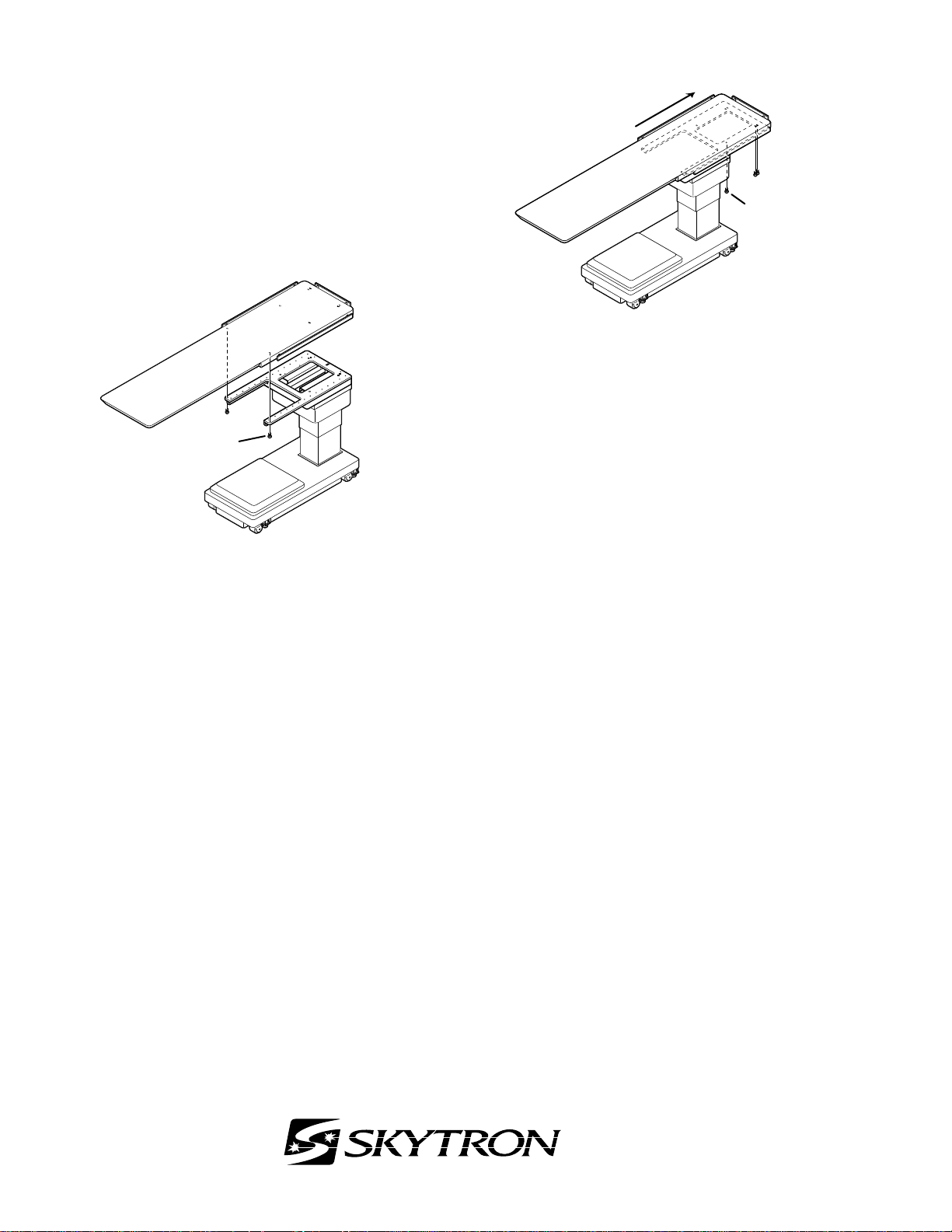
Top Installation Procedure
6)
The carbon fiber top is shipped in a separate crate
along with the table.
SLIDE
1. Remove the Table Top from the crate, align the
top with the base, and install (2) of the M12X30
bolts provided. See figure 8.
BOLT
M12X30 (2)
Figure 8.
3. Plug power cord into 120 VAC outlet, turn Main
Power Switch ON, and use the hand control to slide
the table top as shown in figure 9. Install the (6)
remaining M12X30 bolts.
BOLT
M12X30 (
Figure 9.
4. Torque all of the bolts to 40 ft. lbs. DO NOT
overtighten. Doing so will damage the top.
NOTE
The bolts supplied with the table are
custom made. Do not use bolts other
than the ones supplied with the table to
ensure proper operation.
Always consult with your SKYTRON representative prior to placing the unit into use.
IMPORTANT
Cycle all functions to be sure the table
operates correctly before delivering to
the surgery area.
1skytron/tables/uncrating instructions/3002
5000 36th Street S.E., Grand Rapids, MI 49512
1-800-SKYTRON or 1-616-957-0500 • FAX 1-616-957-5053
 Loading...