


Operators and Safety Manual
Operators and Safety Manual
Model
3606
8990298-004
November 1999
ANSI
Model
3606
8990298-004
November 1999
ANSI

WARNING
Improper operation of this vehicle can cause injury or death.
Before starting the engine, do the following:
1. Read this owner/operators manual.
2. Read all the safety decals on the vehicle.
3. Clear the area of other persons.
Learn and practice safe use of vehicle controls in a safe, clear
area before you operate this vehicle on a worksite.
It is your responsibility to observe applicable laws and
regulations and to follow manufacturer's instructions on vehicle
operation and maintenance.
CALIFORNIA
Proposition 65 Warning
Diesel Engine exhaust and some of its constituents
are known to the State of California to cause
cancer, birth defects and other reproductive harm.

Table of Contents
Table of Contents
1
Introduction
The Manual....................................2
Replacement Parts........................2
Reports..........................................2
Safety Practices
Disclaimer......................................3
Hazard Classification System........3
New or Additional Operators .........4
Personal Considerations ...............4
Operational Considerations...........8
Equipment Considerations ..........13
Operation
Operator Controls........................18
Operators Display Panel..............31
Instruments and Indicators..........36
Optional Controls.........................38
Pre-Operation Inspection.............43
Normal Starting............................44
Cold Starting (Perkins) ................45
Cold Starting (Cummins).............47
Jump Starting ..............................50
Refueling .....................................51
Operating.....................................53
Using the Capacity Chart.............68
Fork Rating..................................75
How To Pick, Carry &
Place A Load ...............................76
Elevating Personnel.....................76
Using Other Attachments ............78
Shut-Off .......................................79
Emergency Operations
Towing a Disabled Vehicle ..........83
Emergency Boom Lowering ........87
General Maintenance
Introduction ...............................100
Maintenance Schedule &
Checklist....................................101
Lubrication Points......................104
Air Cleaner ................................106
Opt. Closed Cab Air Filters........109
Engine Cooling System.............111
Engine Oil and Filter..................114
Engine Fuel System..................117
Engine Fan Belt.........................126
Hydraulic Oil and Filter..............128
Transmission Oil and Filter........131
Axle Oil......................................133
Wheel End Oil ...........................134
Transfer Case Oil ......................136
Wheels and Tires ......................138
Battery.......................................139
Fuse & Relay Replacement.......142
Boom Chains & Wear Pads.......146
Storage......................................150
Transport...................................151
Specifications
Fluid & Lubrication Capacities...152
Tires ..........................................153
Weights .....................................154
Vehicle Dimensions...................154
Electrical System.......................155
Engine .......................................156
1
Introduction
Introduction
The Manual
This Owners/Operators Manual provides the information you need to
correctly operate and maintain this vehicle.
IMPORTANT! Before
you operate this vehicle, read this manual completely
and carefully so you will understand the instructions and the proper
operation of the controls and equipment. You must comply with all
Warning
All references to the right side, left side, front, or rear are given from the
operator's seat looking forward.
Sky Trak International is hereinafter referred to as
, and
Caution
notices; they are for your benefit.
Sky Trak
Danger
.
Replacement Parts
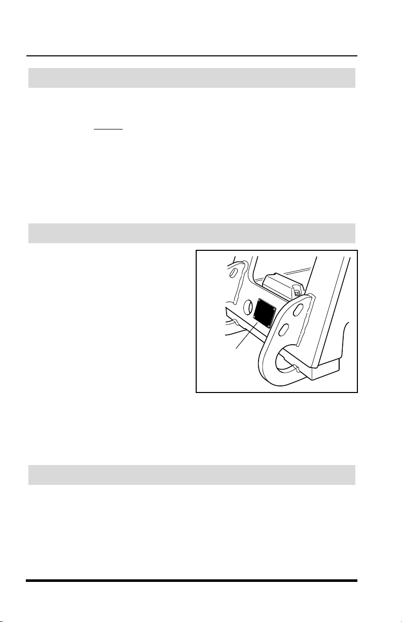
For easy reference when ordering
replacement parts or making service
inquiries on this vehicle, record its
model and serial number on the back
cover of this manual. The serial
number and work order number are
stamped into the serial number plate
which is located on the front of the
vehicle’s frame.
Serial
Number
Plate
OS0013
,
IMPORTANT! The replacement of any part on this vehicle by anything
other than a
Sky Trak
authorized replacement part may adversely affect the
performance, durability or safety of this vehicle and may void the warranty.
Sky Trak assumes no liability for unauthorized replacement parts which
adversely affect the performance, durability or safety of this vehicle.
Reports
IMPORTANT!
A Warranty Registration form must be filled out by the
Trak distributor, signed by the purchaser, and returned to Sky Trak once the
product is sold and/or put into service. This report activates the warranty
period, assuring that your claims during the warranty period will be
processed promptly. To guarantee full warranty service, make sure your
distributor has returned the business reply card of this form to Sky Trak.
2
3606 Rev 11/99
Sky
Safety Practices
Safety Practices
3606 Rev 11/99
3
Sky Trak
reserves the right to make changes on and to add improvements
upon its products at any time without public notice or obligation.
Sky Trak
also reserves the right to discontinue manufacturing any product at its
discretion at any time.
The information in this manual does not replace any safety rules and laws
used in your area. Before operating this vehicle, learn the rules and laws for
your area. Make sure the vehicle has the correct equipment according to
these rules and laws.
Your safety and the safety of others in the worksite depend significantly
upon your knowlege and understanding of all correct operating practices
and procedures for this vehicle.
Safety Practices
This safety alert symbol is used with the following signal words to attract
your attention to messages found within the manual and on safety decals
located on the vehicle. They are reproduced herein and pertain to proper
operation and procedure messages contained throughout the manual. The
message that follows the symbol contains important information about
Safety. To avoid possible injury or death, carefully read and follow the
messages! Be sure to fully understand the potential causes of injury or
death.
Signal Word:
A distinctive word used throughout this manual that alerts the reader to the
existence and relative degree of the hazard on or near the vehicle.
Disclaimer
WARNING
DO NOT
modify or alter (weld, drill, etc.) any part of this vehicle without
consulting
Sky Trak
. Modifications can weaken the structure creating a
hazard that can cause injury or death.
Hazard Classification System
OP0330
Disclaimer
reserves the right to make changes on and to add improvements
Sky Trak
upon its products at any time without public notice or obligation.
also reserves the right to discontinue manufacturing any product at its
discretion at any time.
The information in this manual does not replace any safety rules and laws
used in your area. Before operating this vehicle, learn the rules and laws for
your area. Make sure the vehicle has the correct equipment according to
these rules and laws.
Your safety and the safety of others in the worksite depend significantly
upon your knowlege and understanding of all correct operating practices
and procedures for this vehicle.
WARNING
modify or alter (weld, drill, etc.) any part of this vehicle without
DO NOT
consulting
hazard that can cause injury or death.
. Modifications can weaken the structure creating a
Sky Trak
Safety Practices
Sky Trak
Hazard Classification System
OP0330
This safety alert symbol is used with the following signal words to attract
your attention to messages found within the manual and on safety decals
located on the vehicle. They are reproduced herein and pertain to proper
operation and procedure messages contained throughout the manual. The
message that follows the symbol contains important information about
Safety. To avoid possible injury or death, carefully read and follow the
messages! Be sure to fully understand the potential causes of injury or
death.
Signal Word:
A distinctive word used throughout this manual that alerts the reader to the
existence and relative degree of the hazard on or near the vehicle.
3606 Rev 11/99
3

Safety Practices
ON0021
The signal word “DANGER” indicates an imminently hazardous situation
which, if not avoided, will result in death or serious injury.
ON0030
The signal word “WARNING” indicates a potentially hazardous situation
which, if not avoided, could result in death or serious injury.
ON0010
The signal word “CAUTION” indicates a potentially hazardous situation
which, if not avoided, may result in minor or moderate injury.
OS2020
The signal word “CAUTION” used without the safety alert symbol indicates
a potentially hazardous situation which, if not avoided, may result in
property damage
New or Additional Operators
At the time of original purchase, the purchaser of this vehicle was instructed
by the seller on its safe and correct use. If this vehicle is to be used by an
employee or is loaned or rented to someone other than the purchaser,
make certain that the new operator reads and understands this Operators
Manual before
operating the vehicle.
In addition, make sure that the new operator has completed a walk-around
inspection of the vehicle, is familiar with all decals and safety equipment on
the vehicle, and has demonstrated the correct use of all controls.
Personal Considerations
1. Seat Belt
Always
4
fasten the seat belt before starting the engine.
3606 Rev 11/99
Safety Practices
Safety Practices
3606 Rev 11/99
5
2. Clothing and Safety Gear
DO NOT
wear loose clothing or jewelry that can get caught on controls
or moving parts. Wear protective clothing and personal safety gear
issued or called for by job conditions.
3. Dismounting
DO NOT
get off the vehicle until you:
•
level the vehicle,
•
ground the carriage,
•
place the travel select lever in (N) NEUTRAL,
•
engage the parking brake switch,
•
turn the engine off, if appropriate,
•
unbuckle the seat belt,
•
exit the vehicle using the hand holds.
4. Chemical Hazards
A. Exhaust Fumes
Fumes from the engine exhaust can cause injury or death.
DO NOT
operate vehicle in an enclosed area without a ventilation system
capable of routing the hazardous fumes outdoors.
B. Explosive Fuel
Engine fuel is
flammable
and can cause a fire and/or an explosion.
Avoid danger by keeping sparks, open flames and smoking
materials away from the vehicle and from fuel during refueling or
when servicing the fuel system. Know where fire extinguishers are
kept on the worksite and how to use them.
OS0023
2. Clothing and Safety Gear
wear loose clothing or jewelry that can get caught on controls
DO NOT
or moving parts. Wear protective clothing and personal safety gear
issued or called for by job conditions.
3. Dismounting
DO NOT
OS0023
get off the vehicle until you:
level the vehicle,
•
ground the carriage,
•
place the travel select lever in (N) NEUTRAL,
•
engage the parking brake switch,
•
turn the engine off, if appropriate,
•
unbuckle the seat belt,
•
exit the vehicle using the hand holds.
•
4. Chemical Hazards
A. Exhaust Fumes
Fumes from the engine exhaust can cause injury or death.
operate vehicle in an enclosed area without a ventilation system
capable of routing the hazardous fumes outdoors.
B. Explosive Fuel
Engine fuel is
Avoid danger by keeping sparks, open flames and smoking
materials away from the vehicle and from fuel during refueling or
when servicing the fuel system. Know where fire extinguishers are
kept on the worksite and how to use them.
3606 Rev 11/99
flammable
DO NOT
and can cause a fire and/or an explosion.
5
Safety Practices
C. Hydraulic Fluid
DO NOT
while the engine is running or when the hydraulic system is under
pressure. Fluid in the hydraulic system is under enough pressure
that it can penetrate the skin causing serious injuries or death.
HOT HYDRAULIC FLUID WILL CAUSE SEVERE BURNS.
for fluid to cool down before disconnecting lines.
DO NOT
cardboard or paper to search for leaks. Wear gloves to protect
hands from spraying fluid.
Hydraulic fluid can cause permanent eye injury. Wear appropriate
eye protection and stop engine and relieve pressure before
disconnecting lines.
If anyone is injured by or if any hydraulic fluid is injected into the
skin, obtain medical attention immediately or gangrene may result.
D. Battery
The following WARNING is intended to supplement and does not
replace the warnings and information provided on the battery by the
battery manufacturer.
attempt to repair or tighten any hydraulic hoses or fittings
use your hand to check for leaks. Use a piece of
Wait
When jump starting the vehicle, carefully follow instructions found
under “Jump Starting” on page 50.
-
OS0621
Keep sparks, flames and lit cigarettes away from the battery at all
times. Lead acid batteries generate
explosive
gases. Severe
chemical burns can result from improper handling of battery
electrolyte. Wear safety glasses and proper protective gear when
handling batteries to prevent electrolyte from coming in contact with
eyes, skin or clothing.
6
3606 Rev 11/99
Safety Practices
Safety Practices
3606 Rev 11/99
7
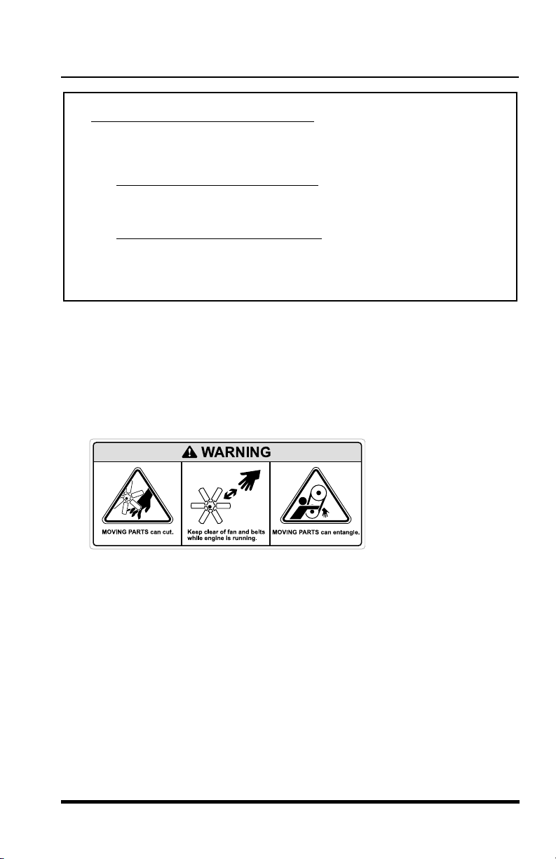
5. Moving Parts Hazard
DO NOT
place limbs near moving parts. Severing of any body part can
result.
Turn off engine and wait until fan and belts stop moving before
servicing.
6. Lowering Boom or Falling Load Hazard
DO NOT
get under a raised boom unless it is blocked up safely. Always
empty the attachment of any load and block the boom up before doing
any servicing that would require the boom to be raised.
NEVER
allow anyone to walk or stand under the boom. A lowering
boom or falling load can result in serious injury or death.
Battery Electrolyte First Aid:
• External Contact —
Flush with water.
•Eyes —
Flush with water for at least 15 minutes and
get medical attention immediately
.
• Internal Contact —
Drink large quantities of water. Follow
with Milk of Magnesia, beaten egg or vegetable oil.
Get medical attention immediately
.
IMPORTANT! In case of internal contact, DO NOT give fluids that
would induce vomiting!
OS0042
Battery Electrolyte First Aid:
Flush with water.
• External Contact —
Flush with water for at least 15 minutes and
•Eyes —
get medical attention immediately
• Internal Contact —
with Milk of Magnesia, beaten egg or vegetable oil.
Get medical attention immediately
IMPORTANT! In case of internal contact, DO NOT give fluids that
would induce vomiting!
5. Moving Parts Hazard
DO NOT
result.
Turn off engine and wait until fan and belts stop moving before
servicing.
place limbs near moving parts. Severing of any body part can
.
Drink large quantities of water. Follow
.
OS0042
6. Lowering Boom or Falling Load Hazard
get under a raised boom unless it is blocked up safely. Always
DO NOT
empty the attachment of any load and block the boom up before doing
any servicing that would require the boom to be raised.
NEVER
boom or falling load can result in serious injury or death.
3606 Rev 11/99
allow anyone to walk or stand under the boom. A lowering
7

Safety Practices
Operational Considerations
1. Preperation and Prevention
Know the location and function of all vehicle controls.
Make sure all persons are away from the vehicle and that the Travel
Select Lever is in the (N) NEUTRAL position with the parking brake
switch engaged before starting the engine.
Holes, obstructions, debris and other worksite hazards can cause injury
or death. Always walk around and look for these and other hazards
before operating the vehicle on a new worksite.
Prevent accidents when you move the vehicle around the worksite.
Know the rules for movement of people and vehicles on the worksite.
Follow the instructions of signals and signs.
DO NOT
•
•
•
2. Clearances
operate the vehicle unless:
all safety equipment is in proper working condition,
all covers and guards are in place, and
all safety and instructional decals are in place and readable.
(Replace all missing, illegible, or damaged decals.)
Look out for and avoid other personnel, machinery and vehicles in the
area. Travel with the boom fully retracted and lowered as far as
possible while still maintaining enough ground clearance for conditions.
Always check boom clearances carefully before driving underneath
door openings, bridges, etc.
Always check for power lines when raising the boom. Beware of
overhead wires, contact with electrical power lines can result in
electrocution. See “Electrocution Hazards” on page 9.
3. Underground Hazards
Know the location of all underground hazards before operating this
vehicle in a new area or worksite. Electrical cables, gas and water
pipes, sewer, or other underground objects can cause injury or death.
Contact your local underground utility service or diggers hotline to mark
all underground hazards.
8
3606 Rev 11/99
Safety Practices
Safety Practices
3606 Rev 11/99
9
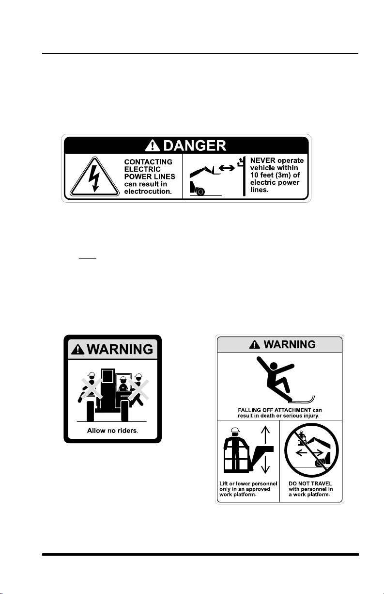
4. Electrocution Hazards
NEVER
operate this vehicle in an area where overhead power lines,
overhead or underground cables, or other power sources may exist
without first requesting that the appropriate power or utility company de-
energize the lines, or take other suitable precautions.
5. Carrying Personnel
Use only an approved work platform for lifting and lowering personnel.
NEVER
transport personnel in a work platform for even the shortest
distance.
Serious injury or death can occur if these rules are not obeyed. Riders
can fall and be crushed or run over. Avoid accidents.
For other specific precautions, see “Elevating Personnel” on page 76.
OS0063
OS0631
OS0072
4. Electrocution Hazards
operate this vehicle in an area where overhead power lines,
NEVER
overhead or underground cables, or other power sources may exist
without first requesting that the appropriate power or utility company deenergize the lines, or take other suitable precautions.
5. Carrying Personnel
Use only an approved work platform for lifting and lowering personnel.
NEVER
distance.
Serious injury or death can occur if these rules are not obeyed. Riders
can fall and be crushed or run over. Avoid accidents.
For other specific precautions, see “Elevating Personnel” on page 76.
OS0063
transport personnel in a work platform for even the shortest
3606 Rev 11/99
OS0072
OS0631
9
Safety Practices
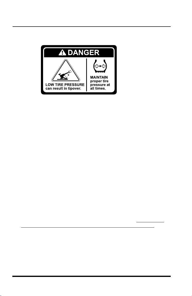
6. Tip Over Hazard
OS1633
MAINTAIN
adversely affects vehicle stability. If proper tire pressures are not
maintained, this vehicle can tip over. If a vehicle ever becomes unstable
and starts to tip over:
Indecision and trying to escape from a tipping vehicle can result in
death or serious injury.
To ensure proper vehicle stability, check all four tire pressures before
operating the vehicle. Maintain proper tire pressures.
DO NOT
damage and unstable conditions will result.
To ensure that the vehicle is positioned in the most stable condition
before operating an attachment:
Use the sway control to level the vehicle. The vehicle is level when the
frame level indicator gauge reaches (0°) zero degrees. If the vehicle
cannot be leveled using the sway control, reposition the vehicle.
Keep the vehicle under control at all times. When negotiating turns,
slow down and turn the steering wheel in a smooth sweeping motion.
Avoid jerky turns, starts or stops. Reduce vehicle speed on rough
ground and slopes.
proper tire pressures at all times. Underpressurized tire(s)
BRACE YOURSELF and STAY WITH THE VEHICLE,
•
KEEP YOUR SEAT BELT FASTENED,
•
HOLD ON FIRMLY and
•
LEAN AWAY FROM THE POINT OF IMPACT.
•
exceed the rated lift capacity of the vehicle as structural
10
3606 Rev 11/99
Safety Practices
Safety Practices
3606 Rev 11/99
11
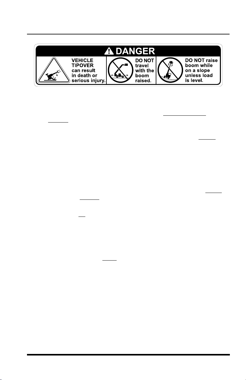
Travelling with the boom raised is dangerous and can cause tipover.
Keep the boom as low as possible. Travel with extreme caution
and at
the slowest
possible speed.
Swaying (frame tilt) left or right with the boom raised above horizontal is
dangerous. Always use the sway control to level the vehicle before
raising the boom above horizontal, with or without a load. If the vehicle
cannot be leveled using sway control, reposition the vehicle.
7. Slopes
DO NOT
park the vehicle on an incline and leave it unattended.
•
Driving across a slope is dangerous, as unexpected changes in
the slope can cause tipover. Ascend or descend slopes slowly
and with caution.
•
Ascend or descend slopes with the heavy end of the vehicle
pointing up
the slope.
NOTE: The rear of the vehicle is normally considered the heavy end unless
the carriage is fully loaded. In this case the front of the vehicle is now the
heavy end.
•
Unloaded vehicles should be operated on all slopes with the
carriage pointing down
the slope.
•
On all slopes, the load must be tilted back and raised only as far
as necessary to clear the ground.
•
When operating on a downhill slope, reduce travel speed and
downshift to a low gear to permit compression braking by the
engine and aid the application of the service brakes.
OS0083
Travelling with the boom raised is dangerous and can cause tipover.
Keep the boom as low as possible. Travel with extreme caution
the slowest
Swaying (frame tilt) left or right with the boom raised above horizontal is
dangerous. Always use the sway control to level the vehicle before
raising the boom above horizontal, with or without a load. If the vehicle
cannot be leveled using sway control, reposition the vehicle.
7. Slopes
DO NOT
•
•
possible speed.
park the vehicle on an incline and leave it unattended.
Driving across a slope is dangerous, as unexpected changes in
the slope can cause tipover. Ascend or descend slopes slowly
and with caution.
Ascend or descend slopes with the heavy end of the vehicle
pointing up
the slope.
and at
OS0083
NOTE: The rear of the vehicle is normally considered the heavy end unless
the carriage is fully loaded. In this case the front of the vehicle is now the
heavy end.
Unloaded vehicles should be operated on all slopes with the
•
carriage pointing down
On all slopes, the load must be tilted back and raised only as far
•
as necessary to clear the ground.
When operating on a downhill slope, reduce travel speed and
•
downshift to a low gear to permit compression braking by the
engine and aid the application of the service brakes.
3606 Rev 11/99
the slope.
11

Safety Practices
8. Falling Load Hazard
DO NOT
being used. Each fork is stamped with a maximum load capacity. If the
capacity is exceeded, forks may break. See “Fork Rating” on page 75.
DO NOT
the load to drop off the forks.
exceed the total rated load capacity of the specific type fork
downshift at a high ground speed. Sudden slowing can cause
9. Visual Obstruction
Dust, smoke, fog, etc. can decrease vision and cause an accident.
Always stop or slow the vehicle until the obstruction clears and the
worksite is visible again.
10.Ventilation
Sparks from the electrical system and the engine exhaust can cause an
explosion.
or vapors, unless good ventilation has removed the hazard.
Carbon monoxide fumes from the engine exhaust can cause
suffocation in an enclosed area. Good ventilation is very important
when operating this vehicle.
DO NOT
operate this vehicle in an area with flammable dust
12
3606 Rev 11/99

Safety Practices
Safety Practices
3606 Rev 11/99
13
DO NOT
by-pass or disconnect any electrical or hydraulic circuits.
Consult the
Sky Trak
service department or your
Sky Trak
distributor if
any circuit is malfunctioning.
DO
check for frayed or cut seat belt webbing, damaged buckles or loose
mounting brackets. Replace immediately if required.
ALWAYS
wear a seat belt when operating the vehicle.
DO
check tire pressure on all four tires. Add air if required.
DO
check the condition of all four rims. Check for bent flanges and/or
bead mounting areas.
DO NOT
operate this vehicle unless all protective covers and guards
are in place and secure. These devices are installed on the vehicle for
your safety and protection.
DO
check the parking brake operation. Repair immediately if required.
DO
keep all non-skid surfaces clean and free of debris. Replace if worn,
damaged or missing.
DO
check the condition of important decals. Replace decals if missing,
damaged or illegible. Figures 1-4 on the following pages show the
proper location of the decals. Figure 1 (page 14) & Figure 2 (page 15)
represent vehicles with Work Order No. 06148 thru 45611. Figure 3
(page 16) & Figure 4 (page 17) represent vehicles with Work Order No.
45612 and After. The Work Order No. is stamped into the serial number
plate located on the front of the frame.
Equipment Considerations
WARNING
DO NOT
modify or alter (weld, drill, etc.) any part of this vehicle without
consulting
Sky Trak
. Modifications can weaken the structure creating a
hazard that can cause injury or death.
Equipment Considerations
WARNING
modify or alter (weld, drill, etc.) any part of this vehicle without
DO NOT
consulting
hazard that can cause injury or death.
DO NOT
Consult the
any circuit is malfunctioning.
DO
mounting brackets. Replace immediately if required.
ALWAYS
DO
DO
bead mounting areas.
DO NOT
are in place and secure. These devices are installed on the vehicle for
your safety and protection.
DO
DO
damaged or missing.
DO
damaged or illegible. Figures 1-4 on the following pages show the
proper location of the decals. Figure 1 (page 14) & Figure 2 (page 15)
represent vehicles with Work Order No. 06148 thru 45611. Figure 3
(page 16) & Figure 4 (page 17) represent vehicles with Work Order No.
45612 and After. The Work Order No. is stamped into the serial number
plate located on the front of the frame.
. Modifications can weaken the structure creating a
Sky Trak
by-pass or disconnect any electrical or hydraulic circuits.
check for frayed or cut seat belt webbing, damaged buckles or loose
wear a seat belt when operating the vehicle.
check tire pressure on all four tires. Add air if required.
check the condition of all four rims. Check for bent flanges and/or
operate this vehicle unless all protective covers and guards
check the parking brake operation. Repair immediately if required.
keep all non-skid surfaces clean and free of debris. Replace if worn,
check the condition of important decals. Replace decals if missing,
service department or your
Sky Trak
Sky Trak
distributor if
3606 Rev 11/99
13
Safety Practices
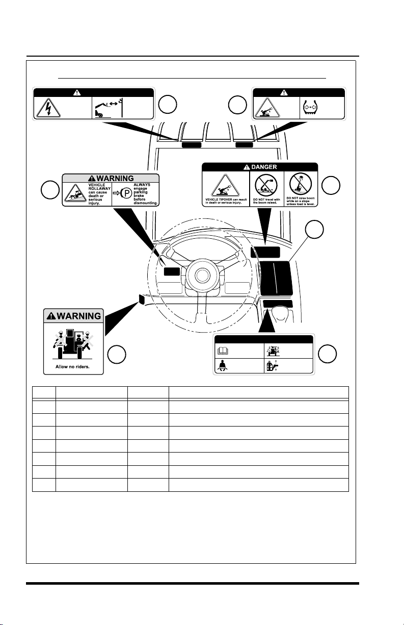
Vehicles Stamped with Work Order No. 06148 thru 45611
CONTACTING
ELECTRIC
POWER LINES
can result in
electrocution.
DANGER
NEVER operate
vehicle within
10 feet (3m) of
electric power
lines.
3
6
DANGER
LOW TIRE
PRESSURE
can result
in tipover.
2
SAFETY INSTRUCTIONS
1. Read operators manual
1
before operating.
2. Fasten seat belt.
Item Part Number Quantity Decal Description
1 mold in dash 1 No Riders Warning
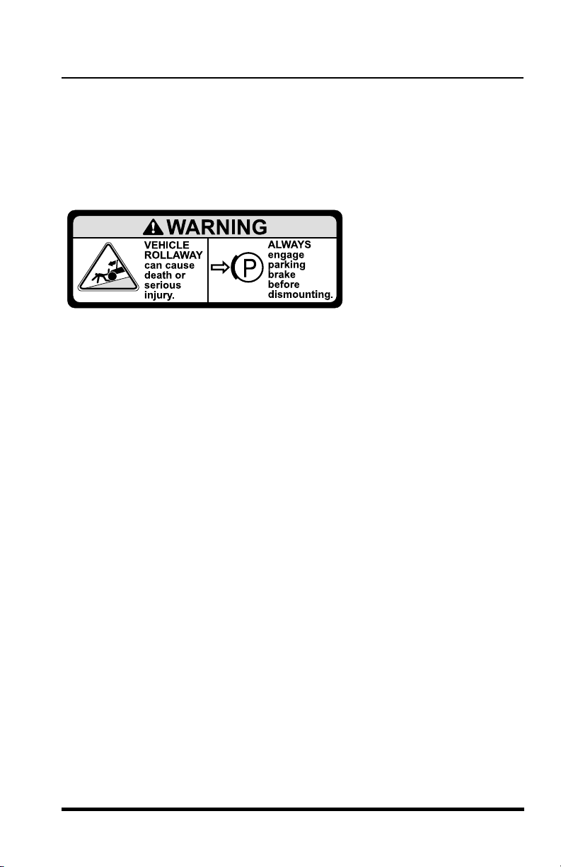
2 mold in dash 1 Vehicle Rollaway Warning
3 4108991 1 Electrocution Danger
4 7134483 1 Load Chart Booklet
5 mold in dash 1 Tipover Danger - Operating
6 4109151 1 Tipover Danger - Tire Pressure
7 4109371 1 Safety Instructions
3. Allow no riders.
4. Use an approved work
platform to lift or lower
personnel.
4
MAINTAIN
proper tire
pressure at
all times.
5
7
OS1511
NOTE:
Many of these hazard related decals are available free of charge
by calling OmniQuip Parts Worldwide at (888) 872-5123.
Figure 1
14
3606 Rev 11/99
Safety Practices
Safety Practices
3606 Rev 11/99
15
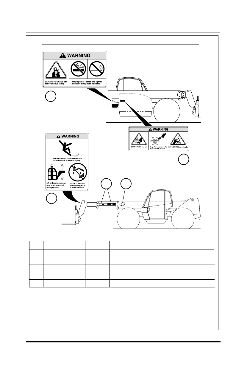
NOTE:
All of these hazard related decals are available free of charge by
calling OmniQuip Parts Worldwide at (888) 872-5123.
Figure 2
Item Part Number Quantity Decal Description
8
4108981 1 Moving Parts Warning
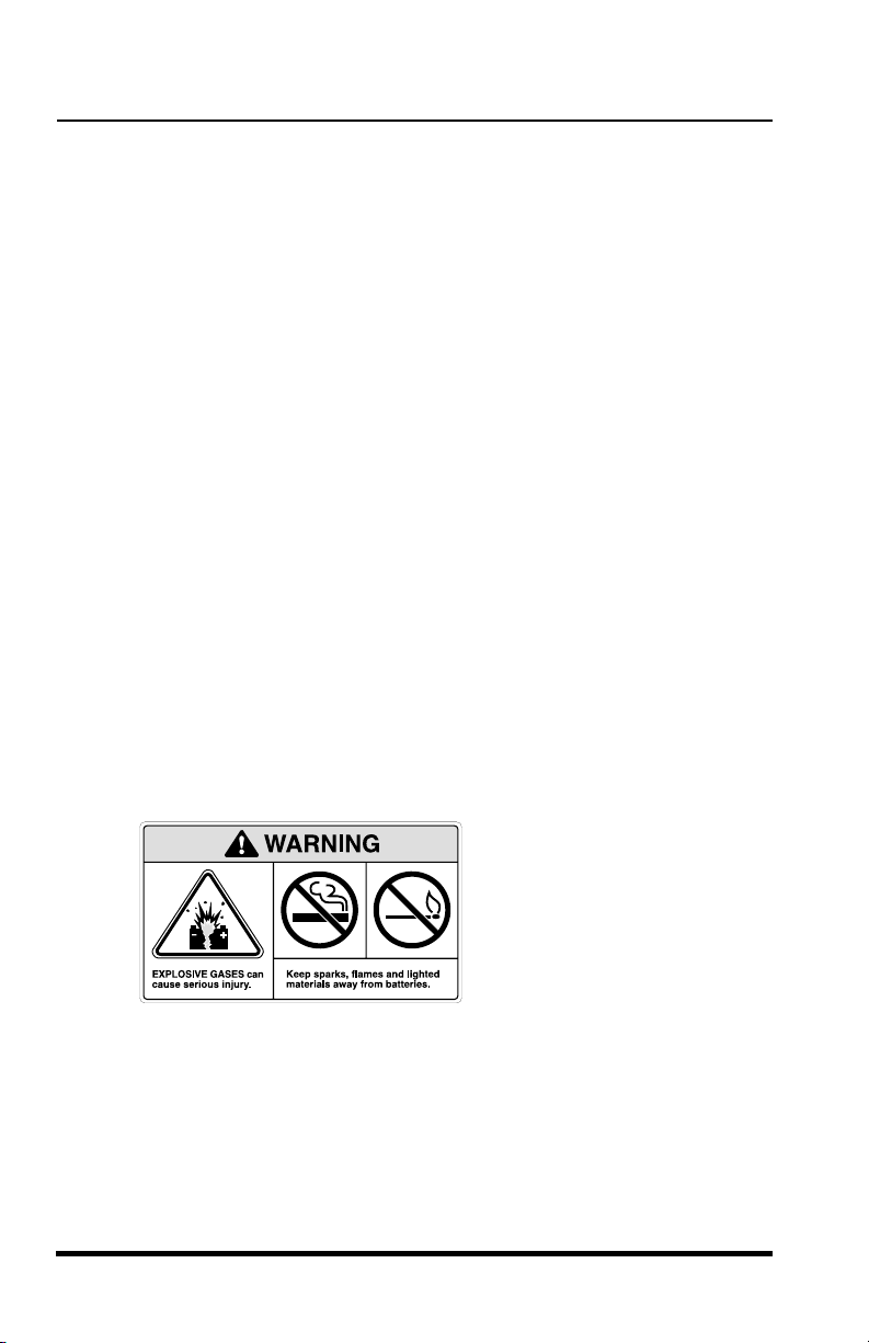
9 4109021 1 Explosive Gases Warning
10 4109041 1 Carrying Personnel Warning
11 4108841 1 Boom Extend Stripes
12 4105262 1 Boom Angle Indicator
OS1256
Vehicles Stamped with Work Order No. 06148 thru 45611
10
8
9
11 12
Vehicles Stamped with Work Order No. 06148 thru 45611
9
8
11 12
10
Item Part Number Quantity Decal Description
8
9 4109021 1 Explosive Gases Warning
10 4109041 1 Carrying Personnel Warning
11 4108841 1 Boom Extend Stripes
12 4105262 1 Boom Angle Indicator
NOTE:
calling OmniQuip Parts Worldwide at (888) 872-5123.
3606 Rev 11/99
4108981 1 Moving Parts Warning
All of these hazard related decals are available free of charge by
Figure 2
OS1256
15
Safety Practices
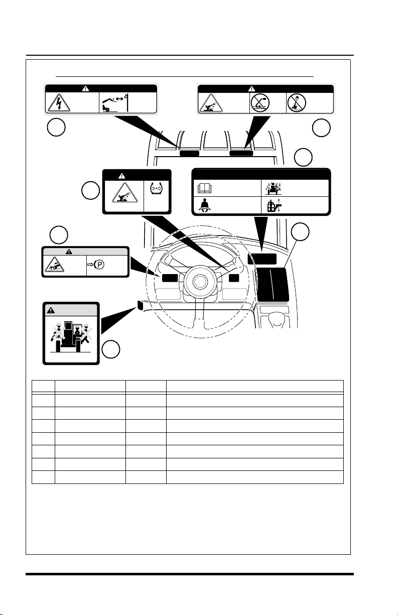
Vehicles Stamped with Work Order No. 45612 and After
CONTACTING
ELECTRIC
POWER LINES
can result in
electrocution.
DANGER
NEVER operate
vehicle within
10 feet (3m) of
electric power
lines.
VEHICLE
TIPOVER
can result
in death or
serious injury.
DANGER
DO NOT
travel
with the
boom
raised.
DO NOT raise
boom while
on a slope
unless load
is level.
3
SAFETY INSTRUCTIONS
1. Read operators manual
before operating.
2. Fasten seat belt.
6
DANGER
LOW TIRE PRESSURE
can result in tipover.
MAINTAIN
proper tire
pressure at
all times.
2
WARNING
VEHICLE
ROLLAWAY
can cause
death or
serious
injury.
WARNING
Allow no riders.
Item Part Number Quantity Decal Description
1
mold in dash 1 No Riders Warning
2 mold in dash 1 Vehicle Rollaway Warning
3 4108991 1 Electrocution Danger
4 7134483 1 Load Chart Booklet
5 4109011 1 Tipover Danger - Operating
6 mold in dash 1 Tipover Danger - Tire Pressure
7 mold in dash 1 Safety Instructions
ALWAYS
engage
parking
brake
before
dismounting.
1
7
3. Allow no riders.
4. Use an approved work
platform to lift or lower
personnel.
4
OS1241
5
NOTE:
Many of these hazard related decals are available free of charge
by calling OmniQuip Parts Worldwide at (888) 872-5123.
Figure 3
16
3606 Rev 11/99
Safety Practices
Safety Practices
3606 Rev 11/99
17
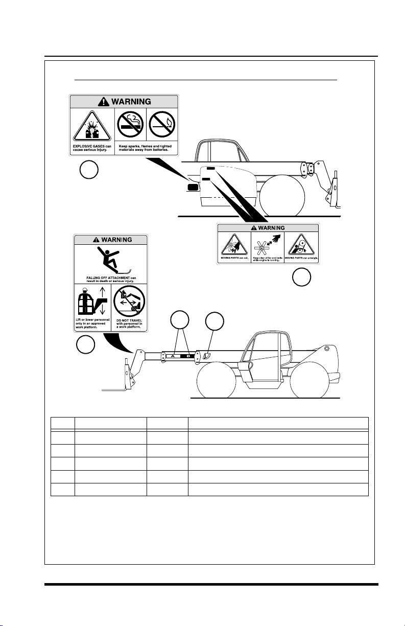
NOTE: All of these hazard related decals are available free of charge by
calling OmniQuip Parts Worldwide at (888) 872-5123.
Figure 4
Item Part Number Quantity Decal Description
8
4108981 2 Moving Parts Warning
9 4109021 1 Explosive Gases Warning
10 4109041 1 Carrying Personnel Warning
11 4108841 1 Boom Extend Stripes
12 4105262 1 Boom Angle Indicator
OS1255
Vehicles Stamped with Work Order No. 45612 and After
9
8
10
12
11
Vehicles Stamped with Work Order No. 45612 and After
9
8
11
12
10
OS1255
Item Part Number Quantity Decal Description
8
9 4109021 1 Explosive Gases Warning
10 4109041 1 Carrying Personnel Warning
11 4108841 1 Boom Extend Stripes
12 4105262 1 Boom Angle Indicator
NOTE: All of these hazard related decals are available free of charge by
calling OmniQuip Parts Worldwide at (888) 872-5123.
3606 Rev 11/99
4108981 2 Moving Parts Warning
Figure 4
17

Operation
Operation
Operator Controls
Accelerator Pedal
(Figure 5)
Pressing down the accelerator pedal increases engine and hydraulic speed
of the vehicle. The pedal is spring-loaded to return to idle speed.
Service Brake Pedal
(Figure 5)
Pressing down the brake pedal decreases the speed of the vehicle by
applying the service brakes located in the axles. In the event of engine
power loss the service brake pedal can also be used for emergency
braking.
Steering Wheel
(Figure 5)
Turning the steering wheel to the left or right steers the vehicle in the
corresponding direction. Any one of three steering modes are selectable.
Refer to “Steering Select Switch” on page 20.
Tilt Steering Wheel Lever
(Figure 6)
To tilt the wheel, hold the steering wheel and pull the lever toward you.
Move the steering wheel to a comfotable operating level, then release the
lever to lock the wheel in place.
Horn Button
(Figure 5)
Pressing the button sounds the horn.
Steering
Wheel
Ignition
Switch
Service
Brake Pedal
Figure 5
18
Horn Button
Accelerator
Pedal
OS0091
3606 Rev 11/99
Operation
Operation
3606 Rev 11/99
19
Figure 6
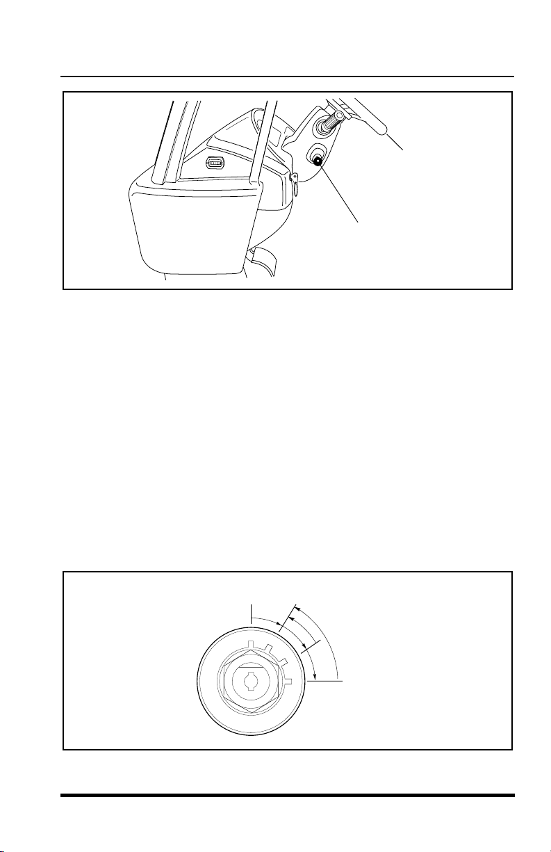
Ignition Switch
(Figure 7)
Using the ignition switch key, the switch may be turned clockwise from the
OFF position to the RUN, PREHEAT and START positions. The PREHEAT
and START positions are spring-loaded to return to the RUN position and
must be manually held in place for starting.
OFF position —
The entire electrical system is shut down.
RUN position —
All controls and indicators are operable.
PREHEAT position —
Optional (Perkins) - Preheats air in the induction
manifold for cold weather starting (see “Cold Starting” on page 45).
START position —
Engages starter motor to crank the engine when the
parking brake switch is engaged and the transmission is in NEUTRAL.
Figure 7
OS1120
Steering
Wheel - Ref.
Tilt Steering
Wheel Lever
OF0390
OFF
RUN
PREHEAT
START
Steering
Wheel - Ref.
Tilt Steering
Wheel Lever
OS1120
Figure 6
Ignition Switch
(Figure 7)
Using the ignition switch key, the switch may be turned clockwise from the
OFF position to the RUN, PREHEAT and START positions. The PREHEAT
and START positions are spring-loaded to return to the RUN position and
must be manually held in place for starting.
The entire electrical system is shut down.
OFF position —
All controls and indicators are operable.
RUN position —
PREHEAT position —
manifold for cold weather starting (see “Cold Starting” on page 45).
START position —
parking brake switch is engaged and the transmission is in NEUTRAL.
3606 Rev 11/99
Optional (Perkins) - Preheats air in the induction
Engages starter motor to crank the engine when the
OFF
RUN
Figure 7
PREHEAT
START
OF0390
19
Operation
Travel and
Gear Select
Lever
Parking
Brake
Switch
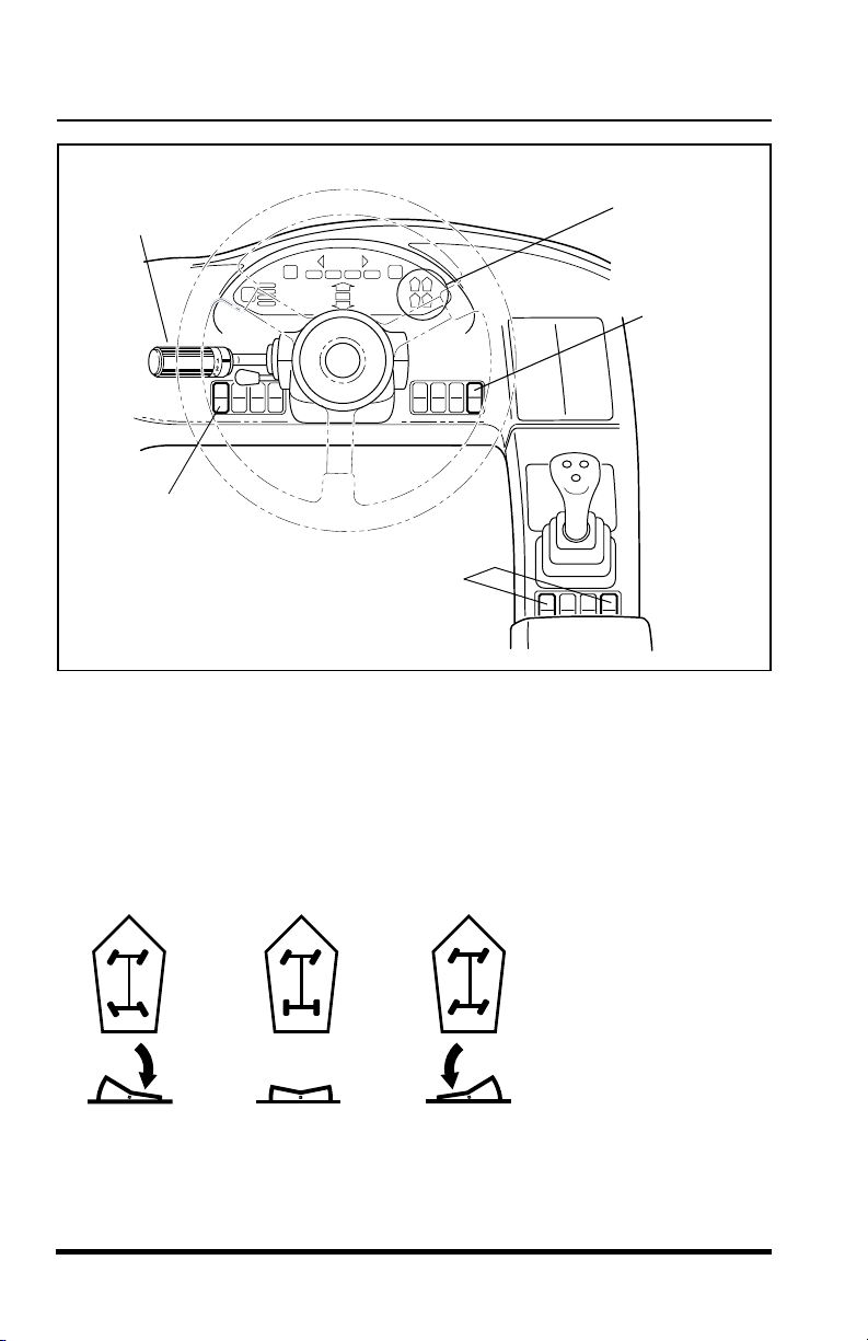
Steering Select Switch
(Either of two locations)
OS0403
Steering Select Switch
(Figure 8)
The switch has three positions:
Steering
Selection
Indicators
Attachment
Tilt Mode
Switch
Figure 8
FOUR
WHEEL
STEERING
FRONT
WHEEL
STEERING
CRAB
STEERING
OS0640
Refer to “Steering Modes” on page 59 for detailed information.
20
3606 Rev 11/99
Operation
Operation
3606 Rev 11/99
21
Parking Brake Switch
(Figure 8)
The parking brake switch has two positions:
Engaged................................ toggle switch downward
Disengaged................................toggle switch upward
The parking brake switch must be ENGAGED to permit engine starting.
The parking brake may be used to stop in an EMERGENCY situation
however, use caution because the stop will be abrupt and the operator and
the load may be jolted forward unexpectedly.
Attachment Tilt Mode Switch
(Figure 8)
The attachment tilt mode switch has two positions which allow the operator
to chose between Lift/Lower function and the Extend/Retract function
accompanying the Attachment Tilt capability. For detailed information, see
“Multi-Function Joystick Operation” starting on page 24.
P
P
OS0121
OS1323
OS2120
Parking Brake Switch
(Figure 8)
The parking brake switch has two positions:
Engaged................................ toggle switch downward
Disengaged................................toggle switch upward
OS1323
The parking brake switch must be ENGAGED to permit engine starting.
The parking brake may be used to stop in an EMERGENCY situation
however, use caution because the stop will be abrupt and the operator and
the load may be jolted forward unexpectedly.
Attachment Tilt Mode Switch
(Figure 8)
The attachment tilt mode switch has two positions which allow the operator
to chose between Lift/Lower function and the Extend/Retract function
accompanying the Attachment Tilt capability. For detailed information, see
“Multi-Function Joystick Operation” starting on page 24.
OS2120
P
P
OS0121
3606 Rev 11/99
21
Operation
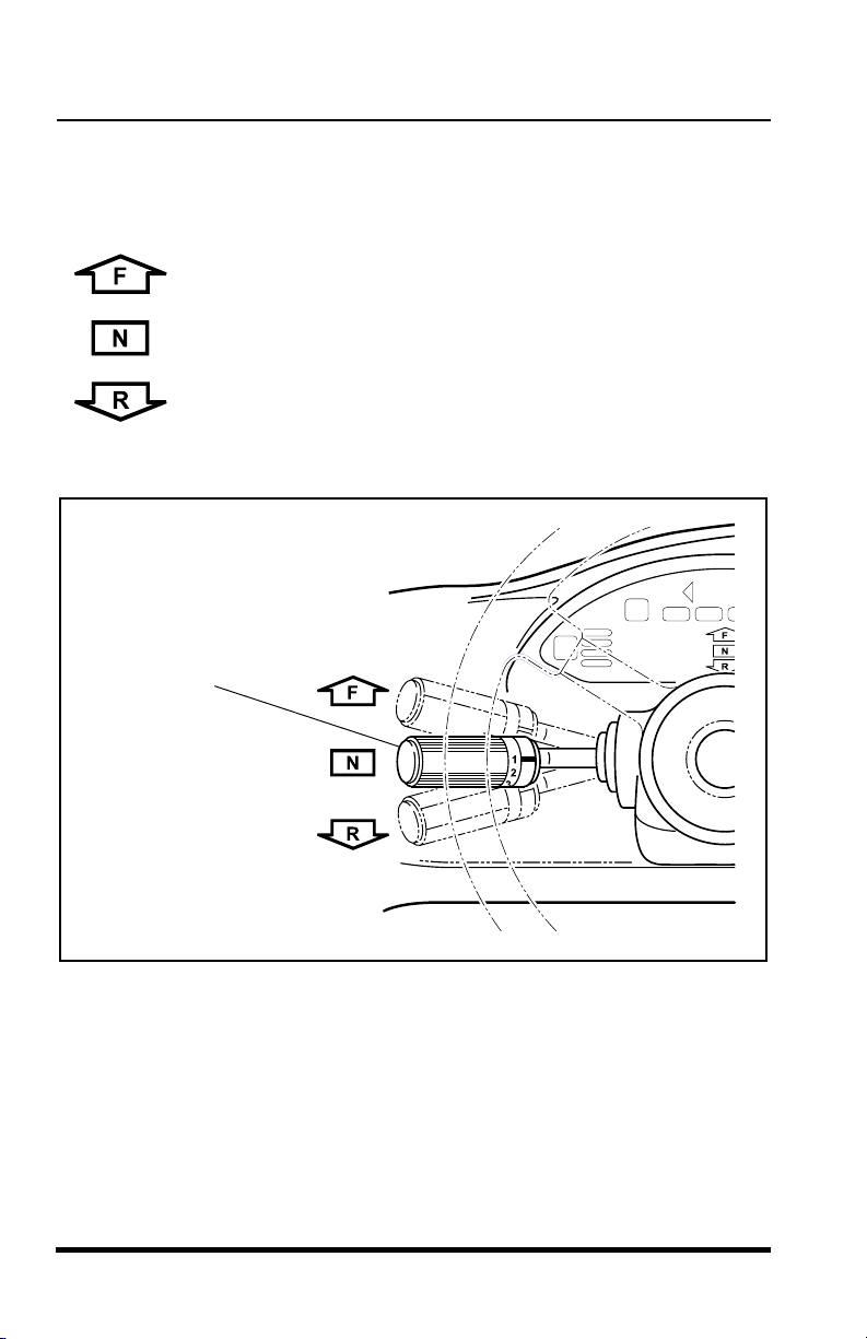
Travel Select Lever
(Figure 9)
The travel select lever has three positions to select direction of travel:
F = FORWARD ...................................all the way UP
N = NEUTRAL ....................................CENTER position
R = REVERSE ....................................all the way DOWN
OS0340
Travel
Select
Lever
OS0130
Figure 9
To change travel selections, grasp the lever and pull it toward the steering
wheel, then UP or DOWN to the desired selection.
When the travel select lever is shifted to REVERSE, the back-up alarm will
automatically sound.
NOTE:
The travel select lever must be in the (N) NEUTRAL position to per-
mit engine starting.
22
3606 Rev 11/99
Operation
Operation
3606 Rev 11/99
23
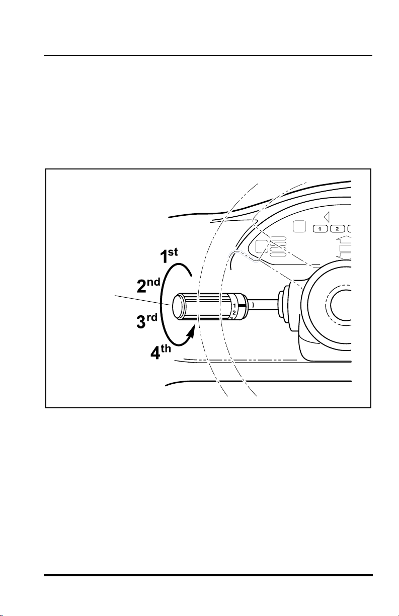
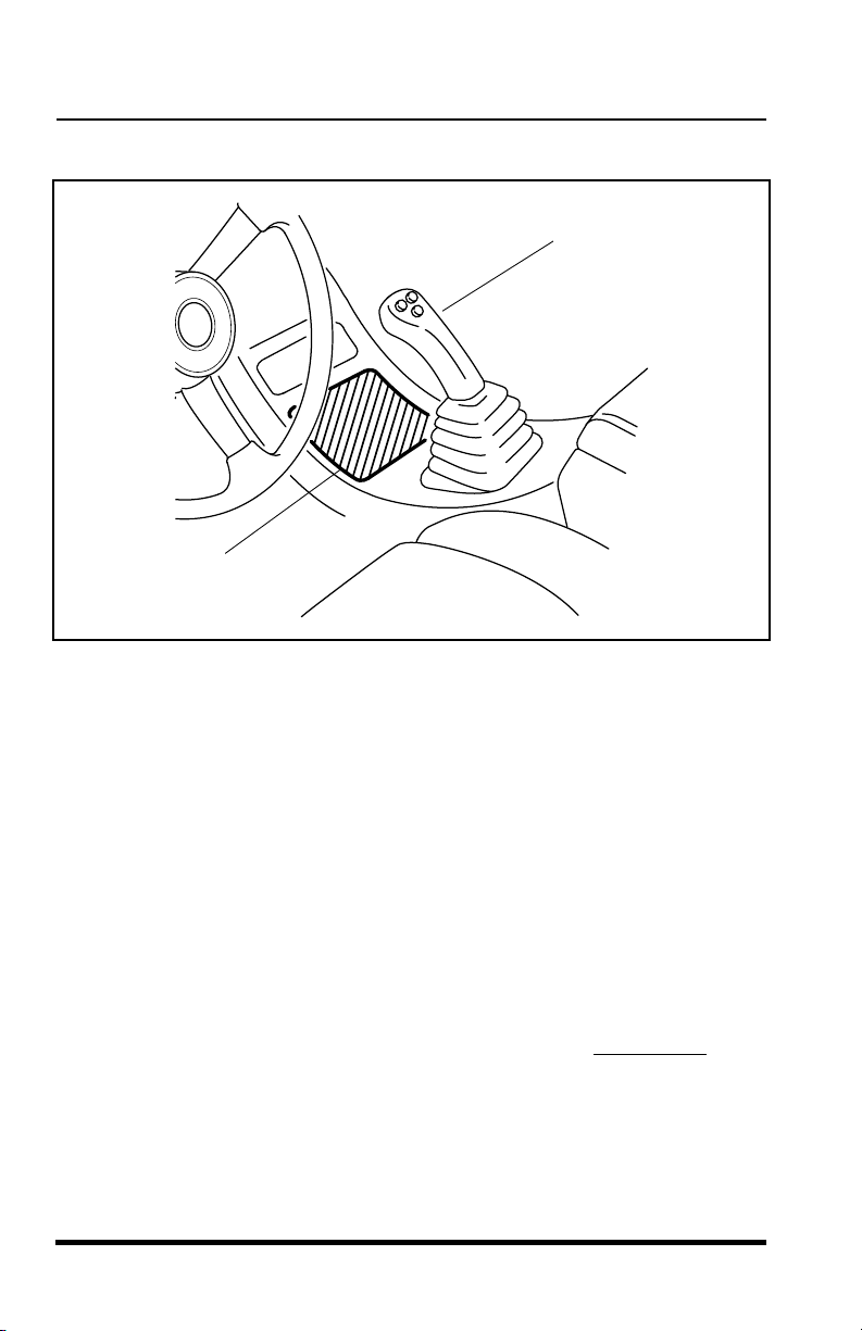
Gear Select Lever
(Figure 10)
The gear select lever has a twist grip handle with four positions. Vehicles
equipped with either Cummins or Perkins turbocharged engine have four (4)
forward gears and three (3) reverse. Vehicles equipped with a naturally
aspirated Perkins engine have three (3) forward gears and three (3) reverse.
Use first gear for highest torque and pulling power. Use higher gears for
higher ground speed.
Figure 10
Gear
Select
Lever
OS0141
Gear Select Lever
(Figure 10)
The gear select lever has a twist grip handle with four positions. Vehicles
equipped with either Cummins or Perkins turbocharged engine have four (4)
forward gears and three (3) reverse. Vehicles equipped with a naturally
aspirated Perkins engine have three (3) forward gears and three (3) reverse.
Use first gear for highest torque and pulling power. Use higher gears for
higher ground speed.
Gear
Select
Lever
3606 Rev 11/99
Figure 10
OS0141
23
Operation
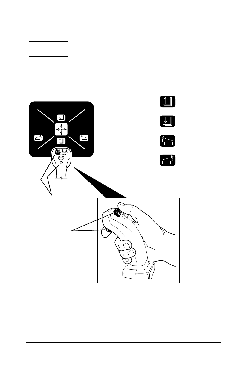
Multi-Function Joystick
(Figure 11)
Multi-Function
Joystick
Logic Panel
OS0152
Figure 11
The joystick is equipped with four buttons that enable the joystick to operate
in four specific modes. The joystick controls boom movement, attachment
tilt, sway control and optional auxiliary hydraulics.
The logic panel (located in front of the joystick) will illuminate the specific
mode that corresponds with the movement of the joystick and the selected
buttons.
Two functions can be accomplished at the same time by moving the joystick
in between quadrants. For example; in Mode 1 moving the joystick forward
and to the left will lower and retract the boom simultaneously.
The speed of movement depends upon the amount of joystick movement in
the corresponding direction. The overall speed of movement depends
directly upon engine speed.
IMPORTANT!
depressing or releasing of any button when the joystick is in an off-center
position.
Be aware that joystick modes will change immediately
upon
24
3606 Rev 11/99
MODE 1
Operation
3606 Rev 11/99
25
OS2050
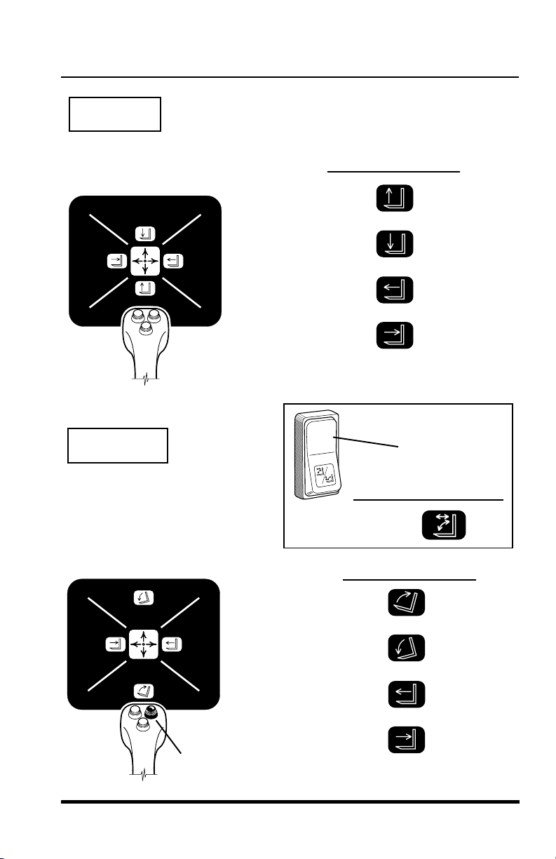
Boom Control (Default)
(No buttons depressed)
MODE 1
move handle
backward
move handle
forward
move handle
to the right
move handle
to the left
Boom Lift ...................
Boom Lower ..............
Boom Extend .............
Boom Retract .............
logic panel symbol
Attachment Tilt Up/Down
& Boom Extend/Retract
(Right button depressed)
MODE 2A
Attachment Tilt with
Extend & Retract
Attachment
Tilt Mode
Switch In
MODE 2A
display panel symbol
OS2060
move handle
backward
move handle
forward
move handle
to the right
move handle
to the left
Attachment Tilt Up ........
Attachment Tilt Down....
Boom Extend ................
Boom Retract ................
Depress
Right Button
logic panel symbol
Boom Control (Default)
(No buttons depressed)
Boom Lift ...................
Boom Lower ..............
Boom Extend .............
OS2050
MODE 2A
Boom Retract .............
Operation
logic panel symbol
move handle
backward
move handle
forward
move handle
to the right
move handle
to the left
Attachment
Tilt Mode
Switch In
MODE 2A
Attachment Tilt Up/Down
& Boom Extend/Retract
(Right button depressed)
Attachment Tilt Up ........
Attachment Tilt Down....
Boom Extend ................
OS2060
Boom Retract ................
Depress
Right Button
3606 Rev 11/99
display panel symbol
Attachment Tilt with
Extend & Retract
logic panel symbol
move handle
backward
move handle
forward
move handle
to the right
move handle
to the left
25
Operation
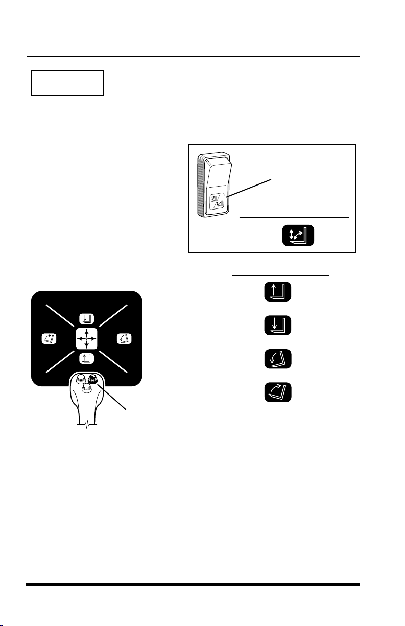
MODE 2B
Boom Lift/Lower &
Attachment Tilt Up/Down
(Right button depressed)
Attachment
Tilt Mode
Switch In
MODE 2B
display panel symbol
Attachment Tilt
with Lift & Lower
logic panel symbol
OS2070
Boom Lift ......................
Boom Lower..................
Attachment Tilt Down ....
Attachment Tilt Up ........
Depress
Right Button
move handle
backward
move handle
forward
move handle
to the right
move handle
to the left
26
3606 Rev 11/99
Operation
Operation
3606 Rev 11/99
27
Boom Lift/Lower & Frame Sway Right/Left
(Depress left & front button simultaneously, then hold either button)
MODE 3
OS2080
move handle
backward
move handle
forward
move handle
to the right
move handle
to the left
Boom Lift ...................
Boom Lower ..............
Frame Sway Right ....
Frame Sway Left ......
logic panel symbol
Depress
Left & Front
Buttons
Simultaneously,
Then Hold
Either
Button
MODE 3
Boom Lift/Lower & Frame Sway Right/Left
(Depress left & front button simultaneously, then hold either button)
logic panel symbol
move handle
backward
move handle
forward
move handle
to the right
move handle
to the left
OS2080
Depress
Left & Front
Buttons
Simultaneously,
Then Hold
Either
Button
Boom Lift ...................
Boom Lower ..............
Frame Sway Right ....
Frame Sway Left ......
3606 Rev 11/99
27
Operation
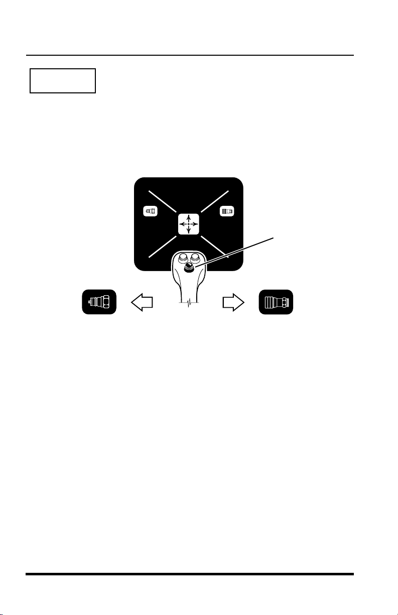
MODE 4
Auxiliary Hydraulic Control - Optional
(Center button depressed)
The auxiliary hydraulic control regulates the functions of an optional
attachment. Some of the optional attachments that require auxiliary hydraulics
are: Side Tilt Carriage, Swing Carriage.
Depress
Center
Button
OS2090
When the joystick is moved to
the left, it will provide hydraulic
system pressure through the
male coupling for the auxiliary
attachment.
The joystick will provide the following typical functions for each specified
attachment listed below if they are connected properly. Operation will be
reversed if incorrectly connected. Shutting the vehicle down, releasing the
hydraulic pressure and reversing the disconnect couplings on the hoses
that are supplied with the attachment will often correct the problem. Contact
your local
information.
Side Tilt Carriage Operation
• Handle right............................. tilt right
• Handle left ............................... tilt left
Swing Carriage Operation
• Handle right............................. swing right
• Handle left ............................... swing left
Sky Trak
distributor or the
28
When the joystick is moved to
the right, it will provide hydraulic
system pressure through the
female coupling for the auxiliary
attachment.
Sky Trak
service department for more
3606 Rev 11/99

Operation
Operation
3606 Rev 11/99
29
Seat Belt
(Figure 12)
The seat belt has one retractable strap for easy installation and removal.
Insert the seat belt tang into the receptacle to fasten. Press the center
button to unfasten the seat belt. Always wear the seat belt when operating
the vehicle. An optional 3 inch wide seat belt is available for those locations
that require a 3 inch seat belt.
Figure 12
OS0200
Seat Belt
Seat Belt
(Figure 12)
The seat belt has one retractable strap for easy installation and removal.
Insert the seat belt tang into the receptacle to fasten. Press the center
button to unfasten the seat belt. Always wear the seat belt when operating
the vehicle. An optional 3 inch wide seat belt is available for those locations
that require a 3 inch seat belt.
Seat Belt
3606 Rev 11/99
Figure 12
OS0200
29

Operation
Operators Seat Adjustments
(Figure 13)
The operator’s seat can be adjusted three ways:
A. Fore and Aft Adjustment -
Pull the handle outward to adjust the seats forward and rearward
position. Release the handle to lock the seat in the desired position.
B. Suspension Adjustment -
Turn the knob or handle on the front of the seat to adjust the
suspension to correspond with the operator’s weight. Turn
clockwise to increase stiffness. Turn counter-clockwise to reduce
the stiffness.
C. Backrest Angle Adjustment -
The angle of the seats backrest can be adjusted to suit the
operator. Move the lever or turn the knob located on the left side of
the seats backrest to adjust the angle.
30
C
C
B
A
A
STANDARD SEAT DELUXE SEAT
OS0200
B
OS2110
Figure 13
3606 Rev 11/99

Operation
Operation
3606 Rev 11/99
31
The display panel provides the operator with important information. It is
“user friendly” and only provides the operator with the information needed at
any given time.
POWER-UP Lights
(Figure 14)
At POWER-UP the display panel will illuminate all its lights for several
seconds as a test function. During this time an audible alarm will sound.
The FASTEN SEAT BELT and READ OPERATOR MANUAL symbols will
remain illuminated for five to seven seconds. This is an important reminder
to the operator to fasten the seat belt and to review the operators manual if
there are any questions about safe operation.
After the five to seven second time period the audible alarm will cease and
the FASTEN SEAT BELT and READ OPERATOR MANUAL symbols will go
out.
If at any time the operator gets up off the seat, these lights will illuminate
again and shut off shortly after the operator sits back down. Do not forget to
refasten your seat belt before operation. Always wear the seat belt when
operating the vehicle.
Figure 14
Operators Display Panel
1
2
34
F
N
R
P
D
OS0222
EARLY PRODUCTION VEHICLES
CURRENT PRODUCTION VEHICLES
Operators Display Panel
The display panel provides the operator with important information. It is
“user friendly” and only provides the operator with the information needed at
any given time.
POWER-UP Lights
(Figure 14)
At POWER-UP the display panel will illuminate all its lights for several
seconds as a test function. During this time an audible alarm will sound.
The FASTEN SEAT BELT and READ OPERATOR MANUAL symbols will
remain illuminated for five to seven seconds. This is an important reminder
to the operator to fasten the seat belt and to review the operators manual if
there are any questions about safe operation.
After the five to seven second time period the audible alarm will cease and
the FASTEN SEAT BELT and READ OPERATOR MANUAL symbols will go
out.
If at any time the operator gets up off the seat, these lights will illuminate
again and shut off shortly after the operator sits back down. Do not forget to
refasten your seat belt before operation. Always wear the seat belt when
operating the vehicle.
3606 Rev 11/99
2
1
D
EARLY PRODUCTION VEHICLES
CURRENT PRODUCTION VEHICLES
34
F
N
R
Figure 14
P
OS0222
31

Operation
Normal Operating Lights
(Figure 15)
After the engine has started, the display panel provides the operator with
information about:
A. Fuel Level Indicators
Make sure the vehicle is level to ensure an accurate fuel level
reading. Each bar represents 1/4 of the tank. The fuel level
indicator symbol will illuminate a low level GREEN light for night
visibility. When 1/8 tank is reached the last bar will turn OFF and the
fuel level indicator symbol will change from a GREEN indicator to
an intense ORANGE indicator light. Refuel at this point.
B. Travel & Gear Select Indicators
The light that illuminates indicates which direction the vehicle is
presently travelling and the gear presently engaged.
C. Steering Mode Indicators
The light that illuminates will indicate which steering mode is
presently engaged.
D. Attachment Tilt Mode Indicator
One of these two lights will be illuminated to indicate which
attachment tilt mode is presently engaged.
32
Fuel Level
Indicator Bars
A
Fuel
Indicator
Symbol
1
Figure 15
B
2
34
F
N
R
Travel
Select Indicators
Gear Select
Indicators
C
D
OS0211
3606 Rev 11/99

Operation
Operation
3606 Rev 11/99
33
Function Indicator Lights
(Figure 16)
There are three “hidden” function indicator lights in the display panel that
become illuminated only when a specific function has been activated. They
are:
A. Engine Preheat Indicator (Optional)
This light will begin to flash when the operator holds the ignition key
in the PREHEAT position. After 30 seconds the light will glow
steadily, indicating the engine is warm enough to start.
B. Parking Brake Indicator
This light becomes illuminated any time the parking brake switch is
applied and the ignition switch is ON.
C. Stabil-TRAK Indicator
This light becomes illuminated when the system has been
activated.
Figure 16
1
2
34
F
N
R
P
1
2
34
F
N
R
P
D
EARLY PRODUCTION VEHICLES
CURRENT PRODUCTION VEHICLES
A
C
B
A
B
C
OS0492
Function Indicator Lights
(Figure 16)
There are three “hidden” function indicator lights in the display panel that
become illuminated only when a specific function has been activated. They
are:
A. Engine Preheat Indicator (Optional)
This light will begin to flash when the operator holds the ignition key
in the PREHEAT position. After 30 seconds the light will glow
steadily, indicating the engine is warm enough to start.
B. Parking Brake Indicator
This light becomes illuminated any time the parking brake switch is
applied and the ignition switch is ON.
C. Stabil-TRAK Indicator
This light becomes illuminated when the system has been
activated.
B
C
A
2
1
34
A
D
3606 Rev 11/99
F
N
R
EARLY PRODUCTION VEHICLES
2
1
CURRENT PRODUCTION VEHICLES
Figure 16
34
F
N
R
P
P
B
C
OS0492
33

Operation
Warning Indicator Lights
(Figure 17)
There are eight additional “hidden” indicator lights in the display panel that
become illuminated during critical circumstances. All eight warning indicator
lights demand immediate attention and vehicle servicing. In many cases the
vehicle should be shut down AS SOON AS PRACTICAL
mechanical failure.
to prevent serious
B
A
2
1
D
E
F
G
C
34
F
N
R
H
Figure 17
The eight warning indicator lights are:
A. Engine Maintenance/Vehicle Lubrication Indicator -
This light becomes illuminated every 250 hours of operation. Call
for service. This indicator reminds the operator that important
maintenance operations are required at this time. After servicing,
the indicator can be reset by depressing and holding the reset
button (Figure 18) then turning the ignition switch to the ON
position. The indicator light will illuminate during power-up and will
go out when it is reset. The reset button can then be released.
B. Engine Coolant Temperature Warning Indicator -
D
OS0531
This light becomes illuminated when the engine coolant
temperature is too high; above 210° F (85° C). An audible alarm will
also sound.
SHUT THE VEHICLE DOWN AS SOON AS PRACTICAL.
C. Transmission Temperature Warning Indicator -
This light becomes illuminated when the transmission oil
temperature is too high; above 250° F (107° C). An audible alarm
34
3606 Rev 11/99

Operation
Operation
3606 Rev 11/99
35
will also sound. Stop and idle the vehicle, allowing time for cooling.
If the light does not go out after five minutes, shut the vehicle down.
Figure 18
D. Hydraulic Oil Temperature Warning Indicator -
This light becomes illuminated when the hydraulic oil temperature is
too high; above 195° F (76° C). Stop and idle the engine, allow time
for cooling. If the light does not go out after five minutes, shut the
vehicle down.
E. Engine Oil Pressure Warning Indicator -
This indicator light will come ON and an audible alarm will sound
after 15 seconds if the engine is not started. This is normal. Turn
the ignition switch OFF to reset the indicator. If the light comes ON
while the engine is running, this indicates that the engine oil
pressure is too low.
SHUT THE VEHICLE DOWN AS SOON AS PRACTICAL.
F. Alternator Charging Warning Indicator -
This light becomes illuminated when the charging system is not
working properly. Service the engine alternator.
G. Engine Air Filter Restriction Warning Indicator -
This light becomes illuminated when a restricted engine air filter is
detected. If the light begins to flicker ON and OFF at high idle,
service the air filter(s).
H. Hydraulic Oil Filter Restriction Warning Indicator -
This light becomes illuminated when a restricted hydraulic oil filter is
detected. If the light begins to flicker ON and OFF at high idle,
service the hydraulic oil filter.
OS0251
Reset
Button
for
Engine
Maintenance/
Vehicle
Lubrication
Indicator
will also sound. Stop and idle the vehicle, allowing time for cooling.
If the light does not go out after five minutes, shut the vehicle down.
Reset
Button
for
Engine
Maintenance/
Vehicle
Lubrication
Indicator
Figure 18
D. Hydraulic Oil Temperature Warning Indicator -
This light becomes illuminated when the hydraulic oil temperature is
too high; above 195° F (76° C). Stop and idle the engine, allow time
for cooling. If the light does not go out after five minutes, shut the
vehicle down.
E. Engine Oil Pressure Warning Indicator -
This indicator light will come ON and an audible alarm will sound
after 15 seconds if the engine is not started. This is normal. Turn
the ignition switch OFF to reset the indicator. If the light comes ON
while the engine is running, this indicates that the engine oil
pressure is too low.
SHUT THE VEHICLE DOWN AS SOON AS PRACTICAL.
OS0251
F. Alternator Charging Warning Indicator -
This light becomes illuminated when the charging system is not
working properly. Service the engine alternator.
G. Engine Air Filter Restriction Warning Indicator -
This light becomes illuminated when a restricted engine air filter is
detected. If the light begins to flicker ON and OFF at high idle,
service the air filter(s).
H. Hydraulic Oil Filter Restriction Warning Indicator -
This light becomes illuminated when a restricted hydraulic oil filter is
detected. If the light begins to flicker ON and OFF at high idle,
service the hydraulic oil filter.
3606 Rev 11/99
35
Operation
Instruments and Indicators
Hourmeter
(Figure 19)
The hourmeter records engine operating hours and has a total readout of
99,999.9 hours. It is located on the left side of the operators console and is
best viewed from outside the vehicle.
Hourmeter
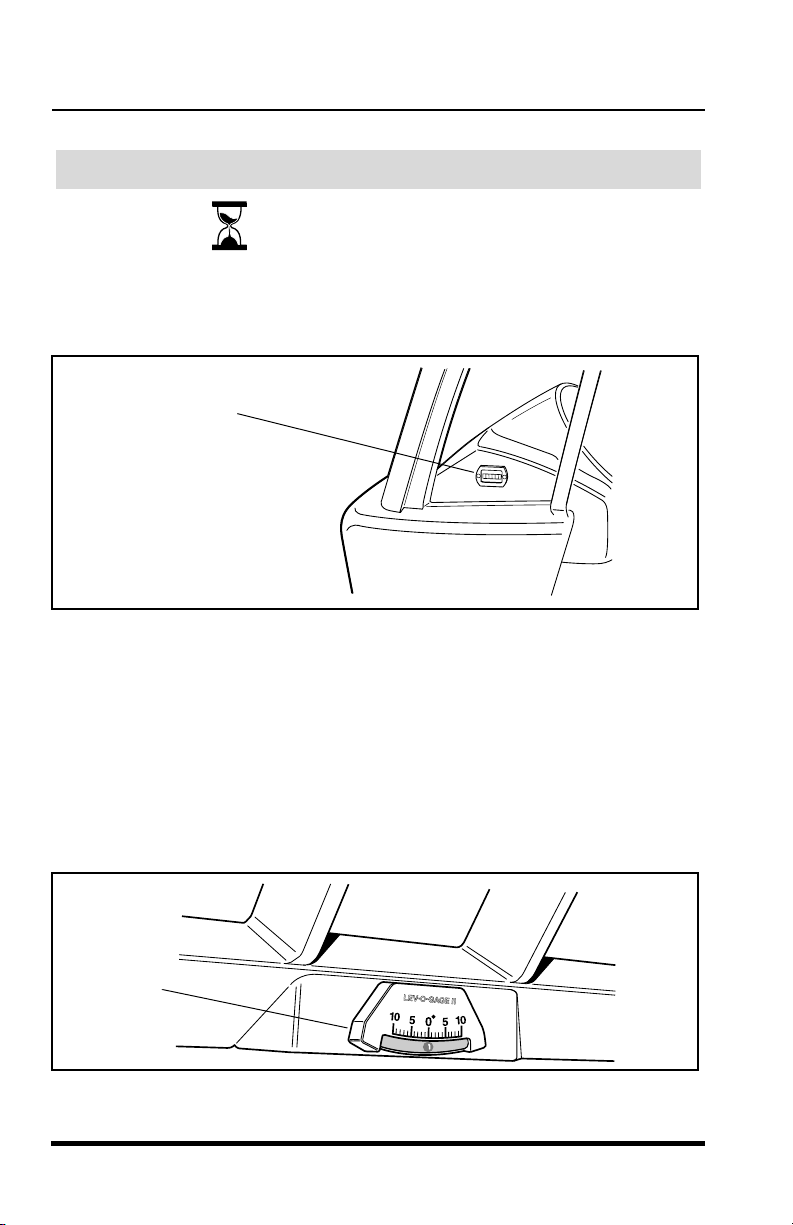
Frame Level Indicator
(Figure 20)
OS0260
OS0750
Figure 19
The frame level indicator is mounted on the top inside of the cab. This is a
bubble type indicator which allows the operator to tell if the vehicle has
been positioned in a level condition. Always sway (frame tilt) the vehicle
either right or left until the indicator reads zero degrees (0°). If zero cannot
be achieved, then reposition the vehicle until it is level before placing the
load.
Frame
Level
Indicator
OS0232
Figure 20
36
3606 Rev 11/99

Operation
Operation
3606 Rev 11/99
37
Boom Angle Indicator
(Figure 21)
The boom angle indicator is a plumb arrow with angular graduations from
-10° to + 80° . It is located on the left side of the boom and is visible from the
operators position. Use this indicator to determine the boom angle when
reading the capacity chart (see “Using the Capacity Chart”).
Figure 21
Rear View Mirrors
(Figure 22)
Two rear view mirrors are provided to aid the operators rear visibility. The
mirrors are adjustable and need to be adjusted to obtain the best rear view
possible for the operator. An optional third mirror is available inside the cab.
Figure 22
OS0240
Boom
Angle
Indicator
OS1050
Two Standard
Rear View Mirrors
OS1470
Cab (Ref.) Engine Cover (Ref.)
Optional
Mirror
Boom Angle Indicator
(Figure 21)
The boom angle indicator is a plumb arrow with angular graduations from
-10° to + 80° . It is located on the left side of the boom and is visible from the
operators position. Use this indicator to determine the boom angle when
reading the capacity chart (see “Using the Capacity Chart”).
Boom
Angle
Indicator
OS0240
Figure 21
Rear View Mirrors
(Figure 22)
Two rear view mirrors are provided to aid the operators rear visibility. The
mirrors are adjustable and need to be adjusted to obtain the best rear view
possible for the operator. An optional third mirror is available inside the cab.
3606 Rev 11/99
Two Standard
Rear View Mirrors
Optional
Mirror
OS1470
Cab (Ref.) Engine Cover (Ref.)
Figure 22
OS1050
37

Operation
Optional Controls
Manually Operated Pressure Release Valve
(Figure 23)
The pressure release valve is located in the rear of the vehicle and is used
to release pressure before connecting
or disconnecting the optional
Auxiliary Hydraulic Couplings.
For a step by step procedure on how to manually operate the pressure
release valve, see page 66 later in this section.
Manually
Operated
Release
Valve
OS2140
OS0360
Figure 23
Lights
(Figure 24)
The lights are activated with a toggle switch located in a bank of switches
on the left side of the dash. There are three positions - OFF, Front Lights
and All Lights (Front Lights & Worklight). The lights work with or without the
ignition switch in the RUN position.
Light Switch
38
OS1900
OS1840
Figure 24
3606 Rev 11/99

Operation
Operation
3606 Rev 11/99
39
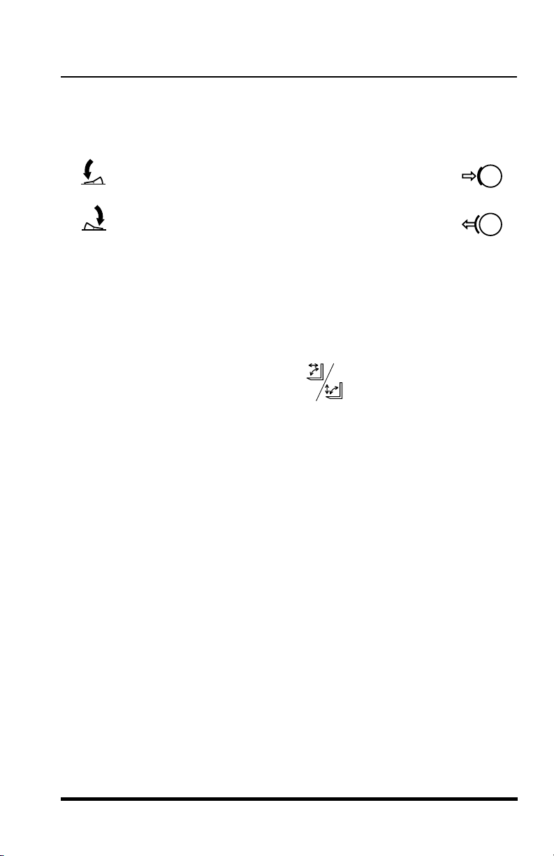
Directional Signals
(Figure 25)
The directional signals are activated from the lever on the right side of the
steering wheel. To activate the left turn signal, raise the lever. To activate the
right turn signal, lower the lever. To deactivate either directional signal, the
lever must be manually returned to the center position, the lever will not
cancel automatically after a turn.
Emergency Flashers
(Figure 25)
To activate the emergency flashers, rotate the twist grip clockwise. To
deactivate the emergency flashers, rotate the twist grip counter-clockwise.
Figure 25
Door Latches
(Not Pictured)
There are two door latches. The outside latch is a key lockable pull to
release type. The inside latch is also a pull to release latch.
OS1910
OS1920
OS1821
Left Turn Signal
Emergency Flashers
Right Turn Signal
Directional Signals
(Figure 25)
The directional signals are activated from the lever on the right side of the
steering wheel. To activate the left turn signal, raise the lever. To activate the
right turn signal, lower the lever. To deactivate either directional signal, the
lever must be manually returned to the center position, the lever will not
cancel automatically after a turn.
Emergency Flashers
(Figure 25)
To activate the emergency flashers, rotate the twist grip clockwise. To
deactivate the emergency flashers, rotate the twist grip counter-clockwise.
OS1910
OS1920
Left Turn Signal
Emergency Flashers
Right Turn Signal
OS1821
Figure 25
Door Latches
(Not Pictured)
There are two door latches. The outside latch is a key lockable pull to
release type. The inside latch is also a pull to release latch.
3606 Rev 11/99
39

Operation
Power Window
(Figure 26)
The power window control is a momentary toggle switch that will raise or
lower the cab door window when the ignition is in the RUN position. To
lower the window, toggle the switch downward to the desired position then
release the switch.
OS1850
NOTE:
The window will not lower entirely into the door; it will stop approxi-
mately half way down and not go any further.
To raise the window, toggle the switch upward to the desired position and
then release the switch.
Cab
Door
Power
Window
Switch
Door
Latch
(Ref.)
OS1800
Figure 26
Rear Window Latches
(Figure 27)
The rear window can be partially opened and secured in place with the rear
window latches. To open the window, grab both latch handles
simultaneously and pull up and then push the window outward. To close
and secure the window, pull both latch handles up and then inward.
NOTE:
window opening by removing the latch pins on both window latches. The
window is then free to swing open.
40
In an emergency situation, the operator can exit through the rear
3606 Rev 11/99

Operation
Operation
3606 Rev 11/99
41
Figure 27
Front Windshield Wiper
Front Windshield Washer
(Figure 28)
The front wiper switch and the front washer switch are separate switches
located in the right-hand bank of switches on the dash.
Skylight Wiper/Washer
(Figure 28)
The skylight (roof) wiper/washer switch is located in the right-hand bank of
switches on the dash.
Figure 28
OS1830
Latch Pin
(Ref.)
Rear
Window
Latch
Handle
OS1930
OS1940
OS2100
OS1840
Front
Washer
Switch
Front
Wiper
Switch
Skylight
Wiper/Washer
Switch
Latch Pin
(Ref.)
Rear
Window
Latch
Handle
OS1830
Figure 27
Front Windshield Wiper
Front Windshield Washer
(Figure 28)
The front wiper switch and the front washer switch are separate switches
located in the right-hand bank of switches on the dash.
Skylight Wiper/Washer
(Figure 28)
The skylight (roof) wiper/washer switch is located in the right-hand bank of
switches on the dash.
OS1930
OS2100
OS1940
Front
Washer
Switch
3606 Rev 11/99
Front
Wiper
Switch
Wiper/Washer
Figure 28
Skylight
Switch
OS1840
41
Operation
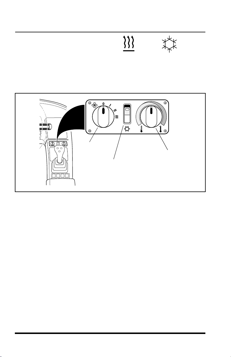
Cab Heater/
Cab Air Conditioning Controls
(Figure 29)
The cab heater and air conditioning controls are located directly below the
vehicles Capacity Chart Booklet. From left to right the control panel consists
of: a stepped fan control knob, an A/C on-off rocker switch (A/C units only),
and a temperature control knob.
Fan
Control
A/C ON-OFF
Rocker Switch
(A/C Units Only)
OS1950
OS1960
Temperature
Control
OS2031
Figure 29
Control of air flow is made by opening, closing or redirecting the air vent
louvers in five seperate locations inside the cab. For instance, if the front
glass needs rapid defrosting, redirect the air flow at the front two vents
(directing the vent louvers toward the glass) and close the remaining three
vents. This will increase the volume of air flow to the front glass and speed
defrosting.
To heat the cab:
if so equipped, turn A/C rocker switch to OFF position,
•
turn temperature control knob to far right position (red = hot),
•
direct desired air flow by adjusting vent louvers,
•
turn fan control to “3” to assure rapid warm-up.
•
42
3606 Rev 11/99

Operation
Operation
3606 Rev 11/99
43
To defrost the cab:
•
turn temperature control knob to far right position (RED=HOT),
•
direct desired air flow by adjusting vent louvers,
•
turn fan control to “3” to assure rapid defrost.
To cool the cab:
•
turn A/C rocker switch to ON position,
•
turn temperature control knob to far left position (BLUE=COOL),
•
direct desired air flow by adjusting vent louvers,
•
turn fan control to “3” to assure rapid cool-down.
1. Check safety belt for damage. Check for frayed or cut seat belt web-
bing, damaged buckles or loose mounting brackets. Make any nec-
essary repairs before operating the vehicle.
2. Check all four tires and rims for damage. Check for proper tire pres-
sure, add air if required. Observe the condition of each tire looking
specifically for punctures, cracks, cuts, gouges, bulges or any other
damage. Check the condition of each rim for bent flanges or any
other damage. Make any necessary repairs before operating the
vehicle.
3. Check and add engine oil if required. This procedure is explained in
greater detail on page 114.
4. Check and add transmission oil if required. This procedure is
explained in greater detail on page 131.
5. Check the cooling system overflow bottle for coolant. Add coolant if
required. This procedure is explained in greater detail on page 111.
Remove any debris blocking the radiator cooling fins.
6. Check the hydraulic oil level sight glass and add hydraulic oil if
required. This procedure is explained in greater detail on page 128.
7. Walk around the vehicle and check for oil leakage as well as dam-
aged or missing parts. Make any necessary repairs before operat-
ing the vehicle.
Pre-Operation Inspection
To defrost the cab:
turn temperature control knob to far right position (RED=HOT),
•
direct desired air flow by adjusting vent louvers,
•
turn fan control to “3” to assure rapid defrost.
•
To cool the cab:
turn A/C rocker switch to ON position,
•
turn temperature control knob to far left position (BLUE=COOL),
•
direct desired air flow by adjusting vent louvers,
•
turn fan control to “3” to assure rapid cool-down.
•
Pre-Operation Inspection
1. Check safety belt for damage. Check for frayed or cut seat belt webbing, damaged buckles or loose mounting brackets. Make any necessary repairs before operating the vehicle.
2. Check all four tires and rims for damage. Check for proper tire pressure, add air if required. Observe the condition of each tire looking
specifically for punctures, cracks, cuts, gouges, bulges or any other
damage. Check the condition of each rim for bent flanges or any
other damage. Make any necessary repairs before operating the
vehicle.
3. Check and add engine oil if required. This procedure is explained in
greater detail on page 114.
4. Check and add transmission oil if required. This procedure is
explained in greater detail on page 131.
5. Check the cooling system overflow bottle for coolant. Add coolant if
required. This procedure is explained in greater detail on page 111.
Remove any debris blocking the radiator cooling fins.
6. Check the hydraulic oil level sight glass and add hydraulic oil if
required. This procedure is explained in greater detail on page 128.
7. Walk around the vehicle and check for oil leakage as well as damaged or missing parts. Make any necessary repairs before operating the vehicle.
3606 Rev 11/99
43

Operation
Normal Starting
1. Enter the cab and adjust the seat for comfortable operation.
2. Adjust the mirrors to obtain the best rear view from the operators
position.
WARNING
DO NOT
fastened around you. Serious injury or death could result if the belt is
not securely fastened.
IMPORTANT! DO NOT
15 seconds. This will avoid starter motor overheating.
start the engine unless you are in the seat with the seat belt
3. Fasten the seat belt.
4. Make sure the parking brake switch is ENGAGED.
5. Place the travel select lever in (N) NEUTRAL.
6. Turn the ignition switch to the START position (fully clockwise) to
crank the engine. Release the key when the engine starts. If the
engine fails to start on the first try, wait until the engine and starter
come to a complete stop before cranking the engine again.
crank the starting motor continuously for more than
7. After the engine starts, run engine at partial throttle for 30 to 60 seconds before operating the vehicle. Return to idle before engaging
the travel or range select levers.
8. Disengage the parking brake switch before you start operating.
44
3606 Rev 11/99

Operation
Operation
3606 Rev 11/99
45
Use the PREHEAT cold starting aid when the temperature is below 32° F
(0° C) with 10W30 oil in the engine crankcase. Using the block heater is
recommended when temperatures fall below 10° F (-12° C). (Temperature
ranges will vary when using different oil weight. Consult the engine
manufacturer’s manual for other variables.)
At temperatures below 10° F (-12° C), operate the engine at moderate
speeds for 5 minutes before full loads are applied.
1. Enter the cab and adjust the seat for comfortable operation. Adjust
the mirrors if necessary.
2. Fasten the seat belt.
3. Make sure the parking brake is engaged.
4. Make sure the travel select lever is in the (N) NEUTRAL position.
Cold Starting
(Perkins Engines Only)
WARNING
This diesel engine uses a PREHEAT system for cold weather starting.
DO NOT
use ether or any high energy fuels to assist starting. An
explosion may cause serious injury or engine damage.
WARNING
DO NOT
start the engine unless you are in the seat with the seat belt
fastened around you. Serious injury or death could result if the belt is
not securely fastened.
Cold Starting
Use the PREHEAT cold starting aid when the temperature is below 32° F
(0° C) with 10W30 oil in the engine crankcase. Using the block heater is
recommended when temperatures fall below 10° F (-12° C). (Temperature
ranges will vary when using different oil weight. Consult the engine
manufacturer’s manual for other variables.)
At temperatures below 10° F (-12° C), operate the engine at moderate
speeds for 5 minutes before full loads are applied.
This diesel engine uses a PREHEAT system for cold weather starting.
use ether or any high energy fuels to assist starting. An
DO NOT
explosion may cause serious injury or engine damage.
1. Enter the cab and adjust the seat for comfortable operation. Adjust
the mirrors if necessary.
(Perkins Engines Only)
WARNING
WARNING
start the engine unless you are in the seat with the seat belt
DO NOT
fastened around you. Serious injury or death could result if the belt is
not securely fastened.
3606 Rev 11/99
2. Fasten the seat belt.
3. Make sure the parking brake is engaged.
4. Make sure the travel select lever is in the (N) NEUTRAL position.
45

Operation
5. Turn and hold the ignition switch to the PREHEAT position until the
preheat indicator light on the display panel stops flashing and glows
steadily. Release the switch immediately after the light goes out.
For location of the preheat indicator light on the display panel see
page 33.
OFF
RUN
PREHEAT
START
OF0390
Figure 30
6. Depress the accelerator pedal completely.
7. Turn the ignition switch to the START position to engage the starter
motor. As the engine starts, release the ignition key to the RUN
position. Release the accelerator pedal enough to provide a smooth
idle speed.
8. If the engine does not start in 15 seconds, return the ignition key to
the PREHEAT position for an additional 10 seconds and then
engage the starter motor again.
46
3606 Rev 11/99

Operation
Operation
3606 Rev 11/99
47
The Cummins engine is equipped with a block heater. Block heaters are
recommended when temperatures drop below 10° F (-12° C).
(Temperature
ranges will vary when using different oil weights. Consult the engine
manufacturer’s manual for other variables.)
At temperatures below 10° F (-12° C), operate the engine at moderate
speeds for 5 minutes before full loads are applied.
1. Enter the cab and adjust the operator’s seat.
2. Fasten the seat belt. Adjust the mirrors if necessary.
3. Make sure the parking brake switch is ENGAGED.
4. Make sure the travel select lever is in the (N) NEUTRAL position.
5. Depress the accelerator pedal half way to the floor.
6. If using starting fluid with mechanical or electrical metering equip-
ment:
•
turn the ignition switch to the START position to engage the
starter motor and inject metered amounts of starting fluid.
•
as the engine starts, stop injection of starting fluid and release
the ignition key to the RUN position. Release the accelerator
pedal enough to provide a smooth idle speed.
Cold Starting
(Cummins Engines Only)
WARNING
DO NOT
start the engine unless you are in the seat with the seat belt
fastened around you. Serious injury or death could result if the belt is
not securely fastened.
Cold Starting
The Cummins engine is equipped with a block heater. Block heaters are
recommended when temperatures drop below 10° F (-12° C).
ranges will vary when using different oil weights. Consult the engine
manufacturer’s manual for other variables.)
At temperatures below 10° F (-12° C), operate the engine at moderate
speeds for 5 minutes before full loads are applied.
1. Enter the cab and adjust the operator’s seat.
start the engine unless you are in the seat with the seat belt
DO NOT
fastened around you. Serious injury or death could result if the belt is
not securely fastened.
2. Fasten the seat belt. Adjust the mirrors if necessary.
3. Make sure the parking brake switch is ENGAGED.
4. Make sure the travel select lever is in the (N) NEUTRAL position.
5. Depress the accelerator pedal half way to the floor.
6. If using starting fluid with mechanical or electrical metering equipment:
turn the ignition switch to the START position to engage the
•
starter motor and inject metered amounts of starting fluid.
as the engine starts, stop injection of starting fluid and release
•
the ignition key to the RUN position. Release the accelerator
pedal enough to provide a smooth idle speed.
(Cummins Engines Only)
WARNING
(Temperature
3606 Rev 11/99
47

Operation
7. If using starting fluid without metering equipment:
WARNING
NEVER
NEVER
heat option or flame air heating equipment.
DO NOT
result from toxic fumes.
DO NOT
engine. Serious injury or death could result from backfire of flame which
could ignite the starting fluid canister and cause an explosion.
IMPORTANT! It is recommended that a second person be present when
attempting to cold start the engine without metered starting fluid equipment.
One person will sit in the operators seat and operate the ignition switch and
another “helper” is needed to spray the starting fluid.
IMPORTANT! It is important to know that timing is crutial in cold starting an
engine.
procedure instructs you to.
use starting fluid near an open flame.
use starting fluid in a vehicle equipped with an electrical pre-
breathe starting fluid fumes. Serious injury or death could
use excessive amounts of starting fluid when cold starting an
DO NOT
spray ether into the air cleaner intake before the
CAUTION
DO NOT
Because it is difficult to describe how much starting fluid should be
used, it is important to avoid soaking the air cleaner element. An
engine backfire could destroy the internal air cleaner elements and
other engine damage may occur. It is much better to spray the fluid
intermittently than continually spraying.
use excessive amounts of starting fluid.
.
48
turn the ignition switch to the START position to engage the
•
starter motor (Figure 31). After the engine has started to crank,
not before
the air cleaner intake (Figure32).
, the other person can begin spraying starting fluid into
3606 Rev 11/99

Operation
Operation
3606 Rev 11/99
49
•
as the engine starts, stop spraying the starting fluid and release
the ignition switch to the RUN position. Release the accelerator
pedal enough to provide a smooth idle speed.
8. The engine oil pressure warning indicator light should go off within
5 seconds after starting. If the light remains on, turn the ignition
switch OFF immediately and check the oil level or change to a
lighter weight oil. Consult the engine manufacturer’s manual for
alternative oils for cold weather operation.
Figure 31
Figure 32
OF0390
OFF
RUN
PREHEAT
START
OS1500
Air
Cleaner
Assembly
Air
Cleaner
Intake
Engine Cover
as the engine starts, stop spraying the starting fluid and release
•
the ignition switch to the RUN position. Release the accelerator
pedal enough to provide a smooth idle speed.
8. The engine oil pressure warning indicator light should go off within
5 seconds after starting. If the light remains on, turn the ignition
switch OFF immediately and check the oil level or change to a
lighter weight oil. Consult the engine manufacturer’s manual for
alternative oils for cold weather operation.
OFF
RUN
Figure 31
PREHEAT
START
OF0390
Air
Cleaner
Assembly
3606 Rev 11/99
Figure 32
Engine Cover
Air
Cleaner
Intake
OS1500
49

Operation
Jump Starting
WARNING
NEVER
Serious injury or death could result from the vehicle lurching forward or
backward and running over the person attempting to jump start the
vehicle directly to the starter.
jump start the vehicle directly to the starter or starter solenoid.
WARNING
To avoid personal injury when jump starting with another vehicle, be
certain that the two vehicles are not touching. Never jump start a frozen
battery as it will explode. Keep sparks, flames and lighted smoking
materials away from the battery. Lead acid batteries generate explosive
gases when charging. Wear safety glasses when working near
batteries.
1. The booster battery must be a 12 volt type. The vehicle used for
jump starting must have a negative ground electrical system. To
jump start the vehicle, proceed as follows:
2. Connect the positive (+) jumper cable to the positive (+) post of the
discharged battery.
3. Connect the other end of the positive (+) jumper cable to the positive (+) post of the booster battery.
4. Connect one end of the negative (-) jumper cable to the negative
(-) post of the booster battery.
5. Make the final cable connection to the engine block ground or the
furthest point from the battery.
6. Follow the steps in “Normal Starting” on page 44.
50
3606 Rev 11/99

Operation
Operation
3606 Rev 11/99
51
7. Remove the jumper cables in the reverse order of their connection
(i.e. negative cable ground connection first, etc.)
Make sure the vehicle is level to assure an accurate fuel level reading. The
fuel tank is capable of holding 35.1 gallons (132,8 liters) of diesel fuel.
Fuel Types
When operating at temperatures above 32° F (0° C) use standard #2 diesel
fuel. When operating at temperatures below 32° F (0° C) use a blend of #1
& #2 diesel fuels, most commonly known as “winterized” #2 diesel. Use
ASTM #2 diesel fuel with a minimum Cetane rating of 40. #2 diesel fuel
gives the best fuel economy and performance under most operating
conditions. Fuels with Cetane ratings higher than 40 may be needed in
higher altitudes or extremely low ambient temperatures to prevent misfiring
and excessive smoke.
Fuel Cap
(Figure 33)
The locking fuel cap is conveniently located on the left side of the vehicle.
The fuel cap meets EPA standards, and a fuel key must be used to unlock
the fuel cap, however the key is not
required to lock the fuel cap.
Refueling
WARNING
Engine fuel is
flammable
and can cause a fire or an explosion. Keep
sparks and open flames away from the vehicle and
DO NOT
use
smoking materials while refueling.
OS0860
7. Remove the jumper cables in the reverse order of their connection
(i.e. negative cable ground connection first, etc.)
Refueling
Make sure the vehicle is level to assure an accurate fuel level reading. The
fuel tank is capable of holding 35.1 gallons (132,8 liters) of diesel fuel.
Fuel Types
OS0860
When operating at temperatures above 32° F (0° C) use standard #2 diesel
fuel. When operating at temperatures below 32° F (0° C) use a blend of #1
& #2 diesel fuels, most commonly known as “winterized” #2 diesel. Use
ASTM #2 diesel fuel with a minimum Cetane rating of 40. #2 diesel fuel
gives the best fuel economy and performance under most operating
conditions. Fuels with Cetane ratings higher than 40 may be needed in
higher altitudes or extremely low ambient temperatures to prevent misfiring
and excessive smoke.
WARNING
Engine fuel is
sparks and open flames away from the vehicle and
smoking materials while refueling.
Fuel Cap
(Figure 33)
The locking fuel cap is conveniently located on the left side of the vehicle.
The fuel cap meets EPA standards, and a fuel key must be used to unlock
the fuel cap, however the key is not
3606 Rev 11/99
flammable
and can cause a fire or an explosion. Keep
use
DO NOT
required to lock the fuel cap.
51

Operation
To unlock the fuel cap:
1. Level the vehicle, ground the carriage, place the travel select lever
in (N) NEUTRAL, engage the parking brake switch and turn the
ignition switch to the OFF position. Remove the keys from the ignition.
Fuel Key
Fuel Cap
Figure 33
2. Insert the fuel key (included with the ignition keys) into the fuel cap
(Figure 33).
3. Turn the key 1/4 turn counterclockwise, then back. Remove the key.
OS0540
WARNING
REMOVE FUEL CAP SLOWLY. Fuel spray may cause injury.
Fuel can spray out on you if you open the cap too quickly.
4.
Slowly
THEN unscrew the cap all the way.
To lock the fuel cap:
1. Turn the cap clockwise until you hear three distinct “clicks”. The fuel
cap is now locked.
52
unscrew the cap and wait for any “hissing” noise to stop.
3606 Rev 11/99

Operation
Operation
3606 Rev 11/99
53
Understanding the Stabil-TRAK™ System
The following describes the three basic modes of the patented Stabil-TRAK
system. The vehicle may operate in any one of these three modes.
Free Pivot Mode
(Figure 34)
With the boom below
40°, the Stabil-TRAK system is in the free pivot mode
and the rear axle is allowed to pivot freely. The frame sway control will
function normally. The Stabil-TRAK light will be OFF.
Figure 34
Operating
OS1970
Stabil-TRAK
Light
"OFF"
Below
40°
FREE
PIVOT
MODE
OS0191
Operating
Understanding the Stabil-TRAK™ System
OS1970
The following describes the three basic modes of the patented Stabil-TRAK
system. The vehicle may operate in any one of these three modes.
Free Pivot Mode
(Figure 34)
With the boom below
and the rear axle is allowed to pivot freely. The frame sway control will
function normally. The Stabil-TRAK light will be OFF.
Below
40°
40°, the Stabil-TRAK system is in the free pivot mode
3606 Rev 11/99
FREE
PIVOT
MODE
Figure 34
Stabil-TRAK
Light
"OFF"
OS0191
53

Operation
Locked Mode
(Figure 35)
With the boom above 40° and
by activating one or more of the following
functions listed below, the Stabil-TRAK system is in the locked mode and
the rear axle is locked so it is rigid with the frame. The Stabil-TRAK light will
be ON.
engaging the parking brake switch
•
placing the travel select lever in (N) NEUTRAL
•
depressing and holding the service brake pedal
•
The frame sway control will function slower than normal in this mode.
Above
40°
LOCKED
MODE
Stabil-TRAK
Light
"ON"
OS1481
Figure 35
Final Positioning Mode
(Figure 36)
With the boom above 40°, the Stabil-TRAK System is now in final
positioning mode. In this mode the rear axle is unlocked and is allowed to
pivot but will respond SLOWLY
light will be OFF.
The frame sway control will function normally in this mode.
IMPORTANT!
It is important that you regularly check that this system is
functioning properly. Refer to the test procedure on page 56 for the proper
system function.
54
to changes in terrain. The Stabil-TRAK
3606 Rev 11/99

Operation
Operation
3606 Rev 11/99
55
Figure 36
Stabil-TRAK™ System Test
IMPORTANT! It is important for the operator to know that the Stabil-TRAK
system is active and functioning properly.
To test the function of the Stabil-TRAK system, read the Stabil-TRAK
system test instructions and follow steps 1 through 9 of the Stabil-TRAK
system test procedure.
Stabil-TRAK™ System Test Instructions
•
Test the Stabil-TRAK system with the vehicle on a level surface.
•
Remove any attachment from the quick attach before performing the test.
•
Perform the test with the boom fully retracted. DO NOT extend the boom
at any time during the test.
DANGER
Vehicle tipover can result in death or serious injury.
DO NOT
use the
vehicle if the Stabil-TRAK system is not functioning properly.
Above
40°
Stabil-TRAK
Light
"OFF"
FINAL
POSITIONING
MODE
OS1492
Above
40°
Stabil-TRAK™ System Test
IMPORTANT! It is important for the operator to know that the Stabil-TRAK
system is active and functioning properly.
FINAL
POSITIONING
MODE
Figure 36
Stabil-TRAK
Light
"OFF"
OS1492
DANGER
Vehicle tipover can result in death or serious injury.
vehicle if the Stabil-TRAK system is not functioning properly.
To test the function of the Stabil-TRAK system, read the Stabil-TRAK
system test instructions and follow steps 1 through 9 of the Stabil-TRAK
system test procedure.
Stabil-TRAK™ System Test Instructions
Test the Stabil-TRAK system with the vehicle on a level surface.
•
Remove any attachment from the quick attach before performing the test.
•
Perform the test with the boom fully retracted. DO NOT extend the boom
•
at any time during the test.
3606 Rev 11/99
DO NOT
use the
55

Operation
DO NOT raise the boom above 60° for steps 3 through 6.
•
DO NOT raise the boom above 45° for steps 7 through 9.
•
Follow steps 1 through 9 of the Stabil-TRAK system test procedure
•
exactly
IMPORTANT! If the Stabil-TRAK light goes OFF and the front left tire
lowers to the ground at any time during steps 4 through 7, the test was not
performed properly or the Stabil-TRAK system is not functioning properly.
Carefully
OFF and the front left tire lowers to the ground consistently during steps 4
through 7, the Stabil-TRAK system is not functioning properly and the test
should be stopped immediately.
system is not functioning properly. Contact your local
immediately to repair the system.
as written.
repeat the steps starting with step 1. If the Stabil-TRAK light goes
DO NOT use the vehicle if the Stabil-TRAK
Sky Trak
Distributor
WARNING
DO NOT
belt fastened around you. Death or serious injury could result if the belt
is not securely fastened.
operate this vehicle unless you are in the seat with the seat
Stabil-TRAK™ System Test Procedures
1. Fasten seat belt and place the vehicle on a level surface with 0°
sway, no load on the forks, boom fully retracted and horizontal.
Check to be sure the Stabil-TRAK light is OFF. See page 33 for the
location of the light in the display panel.
2. Locate an 8 inch (203,2 mm) wood or cement block in front of the
left front tire and drive the vehicle up on the block. Use the frame
sway control to level the vehicle back to 0°.
3. With the service brake pedal depressed, the parking brake switch
OFF, move the travel select lever to the (N) NEUTRAL position and
raise the boom to exactly 60°
ON when the boom angle is at about 40° and remain ON.
IMPORTANT!
4. While the service brake pedal is depressed, move the travel select
lever to the (R) REVERSE position. Ease your foot off the service
Perform procedures 4 through 9 with the engine rpm at idle.
56
. The Stabil-TRAK light should come
3606 Rev 11/99

Operation
Operation
3606 Rev 11/99
57
brake pedal and increase the engine RPM slightly if necessary just
enough to back the vehicle off the block, while keeping the service
brake pedal partially depressed so the Stabil-TRAK light remains
ON. The rear axle should remain locked while backing off the block
and the front left tire should remain off the ground.
5. While keeping the service brake pedal depressed, move the travel
select lever to the (N) NEUTRAL position and take your foot off the
service brake pedal. The rear axle should remain locked, the Stabil-
TRAK light should remain ON, and the front left tire should remain
off the ground.
6. With the travel select lever in the (N) NEUTRAL position, engage
the parking brake switch and move the travel select to the
(F) FORWARD position. The rear axle should remain locked, the
Stabil-TRAK light should remain ON, and the front left tire should
remain off the ground.
7. With the parking brake switch ON, move the travel select lever to
the (N) NEUTRAL position, and lower the boom to exactly 45°
. Use
the frame sway control to tilt the vehicle no more than 5° to the left
and then no more than 5° to the right. The vehicle should sway
slowly to the left and then to the right. The Stabil-TRAK light should
remain ON, and the left front tire should remain off the ground. The
front left tire should not raise or lower when swaying. Leave the
vehicle swayed to the right 1° to 2°.
8. Depress the service brake pedal. Disengage the parking brake
switch and move the travel select lever to the (R) REVERSE posi-
tion. Release the service brake pedal to deactivate the Stabil-TRAK
system and the Stabil-TRAK light should go OFF. The left front tire
should return to the ground while the vehicle travels in reverse.
Depress the service brake pedal to stop the vehicle.
9. With the service brake pedal depressed, boom angle at exactly 45°
,
move the range select lever to (3) third and the travel select lever to
(F) FORWARD. Release the service brake pedal to deactivate the
Stabil-TRAK system and the Stabil-TRAK light should go OFF.
Slowly drive the vehicle forward against the block to stop the vehicle
from moving forward. With the front left tire against the block, frame
sway the vehicle no more than 5° in both directions while checking
that the front tires remain on the ground. It is normal for the left front
tire to raise slightly when swaying to the left and for the front right
tire to raise slightly when swaying to the right, but the tires should
immediately lower when the frame sway function is stopped. The
tires should not come completely off the ground during this step.
Frame sway the vehicle back to 0°. Depress the service brake
pedal, shift the travel select lever to (N) NEUTRAL and lower the
boom.
brake pedal and increase the engine RPM slightly if necessary just
enough to back the vehicle off the block, while keeping the service
brake pedal partially depressed so the Stabil-TRAK light remains
ON. The rear axle should remain locked while backing off the block
and the front left tire should remain off the ground.
5. While keeping the service brake pedal depressed, move the travel
select lever to the (N) NEUTRAL position and take your foot off the
service brake pedal. The rear axle should remain locked, the StabilTRAK light should remain ON, and the front left tire should remain
off the ground.
6. With the travel select lever in the (N) NEUTRAL position, engage
the parking brake switch and move the travel select to the
(F) FORWARD position. The rear axle should remain locked, the
Stabil-TRAK light should remain ON, and the front left tire should
remain off the ground.
7. With the parking brake switch ON, move the travel select lever to
the (N) NEUTRAL position, and lower the boom to exactly 45°
the frame sway control to tilt the vehicle no more than 5° to the left
and then no more than 5° to the right. The vehicle should sway
slowly to the left and then to the right. The Stabil-TRAK light should
remain ON, and the left front tire should remain off the ground. The
front left tire should not raise or lower when swaying. Leave the
vehicle swayed to the right 1° to 2°.
8. Depress the service brake pedal. Disengage the parking brake
switch and move the travel select lever to the (R) REVERSE position. Release the service brake pedal to deactivate the Stabil-TRAK
system and the Stabil-TRAK light should go OFF. The left front tire
should return to the ground while the vehicle travels in reverse.
Depress the service brake pedal to stop the vehicle.
9. With the service brake pedal depressed, boom angle at exactly 45°
move the range select lever to (3) third and the travel select lever to
(F) FORWARD. Release the service brake pedal to deactivate the
Stabil-TRAK system and the Stabil-TRAK light should go OFF.
Slowly drive the vehicle forward against the block to stop the vehicle
from moving forward. With the front left tire against the block, frame
sway the vehicle no more than 5° in both directions while checking
that the front tires remain on the ground. It is normal for the left front
tire to raise slightly when swaying to the left and for the front right
tire to raise slightly when swaying to the right, but the tires should
immediately lower when the frame sway function is stopped. The
tires should not come completely off the ground during this step.
Frame sway the vehicle back to 0°. Depress the service brake
pedal, shift the travel select lever to (N) NEUTRAL and lower the
boom.
. Use
,
3606 Rev 11/99
57

Operation
If steps 1 through 9 prove positive, the Stabil-TRAK system is functioning
properly and the vehicle can be returned to service. If any of these steps
indicate that the Stabil-TRAK system is not functioning properly, contact
your local
Sky Trak
Starting Travel
1. Enter the operator cab, fasten the seat belt, start the engine, apply
the service brake pedal and disengage the parking brake switch.
2. Rotate the twist grip of the range select lever to 1st gear.
3. Move the travel select lever to (F) FORWARD to travel in a forward
direction or to (R) REVERSE to travel backward.
4. Slowly remove your foot from the service brake pedal and press the
accelerator pedal to start travel.
IMPORTANT!
abnormal indication should be corrected as soon as practical.
Changing Travel Direction
1. Stop the vehicle by applying the service brakes.
2. Grasp the travel select lever, pull it toward the steering wheel then
move the lever up or down to the opposite direction;
(R) REVERSE or (F) FORWARD.
Distributor immediately to repair the system.
Check for warning lights frequently during operation. Any
Shifting Gears
1. Rotate the twist grip of the gear select lever to the next desired
gear.
NOTE: Shifting to the next higher gear may be done while the vehicle is in
motion.
IMPORTANT!
before shifting to the next lower gear.
Both vehicles equipped with Turbocharged engines have four speed
transmissions, however vehicles equipped with the Naturally Aspirated
Perkins engine have three speed transmissions. Shifting into the fourth
forward gear with the above descibed vehicle will have no effect.
58
When downshifting, allow the engine speed to slow down
3606 Rev 11/99

Operation
Operation
3606 Rev 11/99
59
Stopping Travel
1. Apply the service brake pedal and downshift the vehicle to a lower
gear if necessary to slow the vehicle until it comes to a complete
stop.
2. Move the travel select lever to (N) NEUTRAL and engage the park-
ing brake switch.
Steering Modes
(Figure 37)
The vehicle can be operated in one of three steering modes:
•
Four Wheel Steering
•
Front Wheel Steering
•
Crab Steering
The steering mode can be changed by a three position toggle switch
located on the right console below the arm rest.
IMPORTANT! DO NOT change steering modes unless you are at a
complete stop and all four tires are in the “straight-ahead” position.
Figure 37
Four
Wheel
Steering
Front
Wheel
Steering
Crab
Steering
STEERING SELECT SWITCH
OS1411
Steering Selection Indicators
Stopping Travel
1. Apply the service brake pedal and downshift the vehicle to a lower
gear if necessary to slow the vehicle until it comes to a complete
stop.
2. Move the travel select lever to (N) NEUTRAL and engage the parking brake switch.
Steering Modes
(Figure 37)
The vehicle can be operated in one of three steering modes:
Four Wheel Steering
•
Front Wheel Steering
•
Crab Steering
•
The steering mode can be changed by a three position toggle switch
located on the right console below the arm rest.
IMPORTANT! DO NOT change steering modes unless you are at a
complete stop and all four tires are in the “straight-ahead” position.
Steering Selection Indicators
Four
Wheel
Steering
Front
Wheel
Steering
Crab
Steering
3606 Rev 11/99
STEERING SELECT SWITCH
Figure 37
OS1411
59

Operation
Four Wheel Steer Indexing
If the vehicle does not drive “straight”, the steering could be “out of phase.”
Perform the following Four Wheel Steer Indexing Procedure to synchronize
the front and rear steering.
Four Wheel Steer Indexing Procedure
1. With the steering select switch in the Four Wheel Steer position,
turn the steering wheel full left. While holding the steering wheel full
left, toggle the steer select switch to the Front Wheel Steer position
and steer the front wheels back to center. Toggle the steer select
switch back to Four Wheel Steer position and turn the steering
wheel full left. Toggle the steer select switch back to Front Wheel
Steer position and steer the front wheels full left. Toggle the switch
to the Four Wheel Steer position and return to center.
2. The vehicle should now be properly indexed in Four Wheel Steering. If the wheels are still out-of-phase, repeat step 1 again.
1. Four Wheel Steering
(Figure 38)
The front wheels will steer in the direction that the steering wheel is turned;
the rear wheels will steer in the opposite direction. This steering mode
allows an extremely short turning radius and enables the rear wheels to
follow the tracking of the front wheels which can be an advantage in mud
and sand conditions.
60
OS0280
Figure 38
3606 Rev 11/99

Operation
Operation
3606 Rev 11/99
61
2. Front Wheel Steering
(Figure 39)
The front wheels will steer in the direction that the steering wheel is turned.
The rear wheels will remain in a fixed forward position. This steering mode
should be used when loading or unloading the vehicle from a trailer and for
on-highway travel at higher speeds.
Figure 39
WARNING
NEVER
use the Four Wheel Steering Mode when traveling at high
speed. Rapid turning in the mode will cause tipover. Use only the Front
Wheel Steering Mode at higher speeds and slow the vehicle when
turning.
OS0290
WARNING
use the Four Wheel Steering Mode when traveling at high
NEVER
speed. Rapid turning in the mode will cause tipover. Use only the Front
Wheel Steering Mode at higher speeds and slow the vehicle when
turning.
2. Front Wheel Steering
(Figure 39)
The front wheels will steer in the direction that the steering wheel is turned.
The rear wheels will remain in a fixed forward position. This steering mode
should be used when loading or unloading the vehicle from a trailer and for
on-highway travel at higher speeds.
3606 Rev 11/99
Figure 39
OS0290
61

Operation
3. Crab Steering
(Figure 40)
All wheels will steer in the same direction that the steering wheel is turned.
This steering mode allows the operator to move the vehicle “sideways”
toward the landing point of a load. This is especially useful on a congested
worksite, in order to line up at the exact spot in front of the loading location.
OS0310
Figure 40
WARNING
NEVER
Rapid turning in this mode will cause tipover. Use only the front wheel
steering mode at higher speeds and slow the vehicle when turning.
62
use the Crab Steering Mode when travelling at high speed.
3606 Rev 11/99

Operation
Operation
3606 Rev 11/99
63
Maximum Fork Sweep
(Figure 41)
Figure 41
CAUTION
Allow for adequate clearance between the attachment and other
objects when turning.
The attachment extends beyond
the end of the vehicle. The operator
must be aware of the maximum sweep of the attachment when turning,
in order to avoid hitting personnel, and other objects in the area.
OS0321
Vehicle
Turning
Radius
Maximum
Fork
Sweep
Center Point of
Turning Radius
Maximum Fork Sweep
(Figure 41)
CAUTION
Allow for adequate clearance between the attachment and other
objects when turning.
The attachment extends beyond
must be aware of the maximum sweep of the attachment when turning,
in order to avoid hitting personnel, and other objects in the area.
the end of the vehicle. The operator
3606 Rev 11/99
Vehicle
Turning
Radius
Center Point of
Turning Radius
Figure 41
Maximum
Fork
Sweep
OS0321
63

Operation
Leveling the Vehicle
When placing a load on a slope, use the Frame Sway Control (see MODE 3
on page 27) to keep the vehicle level. The operator should observe the
frame level indicator to assure that the vehicle is level at all times.
WARNING
Use of frame sway control with the boom raised above horizontal can
cause tipover resulting in death or serious injury. Always use the sway
control to level the vehicle before
the vehicle cannot be leveled using the sway control, reposition the
vehicle.
Quick Attach
This vehicle is equipped with a quick attach system for easy attachment
changing.
raising the boom above horizontal. If
Attachment Removal
1. Be sure you are performing this procedure on level ground.
2. Place the travel select lever in (N) NEUTRAL, come to a complete
stop and engage the parking brake switch.
3. Extend the boom approximately 10 feet (3,05 meters) and tilt the
carriage backward.
4. Exit the vehicle using both hand holds.
NOTE:
apart on the carriage shaft. This will provide the carriage adequate support
to stand alone.
64
If you are removing a standard carriage with forks, spread the forks
5. Raise the quick attach pin lock lever and pull out the pin at the bottom of the quick attach link (Figure 42).
3606 Rev 11/99

Operation
Operation
3606 Rev 11/99
65
Figure 42
6. Return to the operators compartment, fasten the seat belt and
lower the attachment to the ground in a level position. Tilt the
attachment forward. This will rotate the quick attach link back away
from the attachment.
7. Lower, then retract the boom until the attachment pivot pins have
disconnected from the attachment.
Attachment Reconnect
1. Be sure you are performing this procedure on level ground. Position
the vehicle directly behind the attachment to be mounted.
2. Tilt the quick attach backward.
3. Extend the boom approximately 10 feet (3,05 meters) and drive the
vehicle forward until the attachment pivot pins are below and
between the two hooks on the attachment.
4. Raise the boom until the attachment pivot pins have seated fully in
the hooks of the attachment.
5. Tilt the attachment up slightly. The quick attach link should be tight
against the rear of the attachment and the holes in the link and the
attachment should be aligned.
OS0331
Quick Attach Pin
Quick
Attach
Pin
Lock
Lever
Quick
Attach
Pin
Lock
Lever
OS0331
Quick Attach Pin
Figure 42
6. Return to the operators compartment, fasten the seat belt and
lower the attachment to the ground in a level position. Tilt the
attachment forward. This will rotate the quick attach link back away
from the attachment.
7. Lower, then retract the boom until the attachment pivot pins have
disconnected from the attachment.
Attachment Reconnect
1. Be sure you are performing this procedure on level ground. Position
the vehicle directly behind the attachment to be mounted.
2. Tilt the quick attach backward.
3. Extend the boom approximately 10 feet (3,05 meters) and drive the
vehicle forward until the attachment pivot pins are below and
between the two hooks on the attachment.
4. Raise the boom until the attachment pivot pins have seated fully in
the hooks of the attachment.
5. Tilt the attachment up slightly. The quick attach link should be tight
against the rear of the attachment and the holes in the link and the
attachment should be aligned.
3606 Rev 11/99
65

Operation
6. Place the travel select lever in (N) NEUTRAL, engage the parking
brake switch and exit the vehicle using both hand holds.
7. Lift the quick attach lever. Insert the quick attach pin completely
through the attachment and the quick attach link. Be sure that the
quick attach lock lever has lowered and seated itself into the groove
in the quick attach pin.
WARNING
DO NOT
belt fastened around you. Serious injury or death could result if the belt
is not securely fastened.
operate this vehicle unless you are in the seat with the seat
8. Return to the cab, fasten the seat belt and resume operation.
Manually Operated Pressure Release Valve
(Figure 43)
The pressure release is located in the rear of the vehicle and is used to
release pressure before connecting
Hydraulic Couplings.
Before connecting
Couplings, it is important to manually release pressure trapped within the
auxiliary hydraulic system.
1. Bring the vehicle to a complete stop using the service brakes.
2. Park the vehicle on level ground.
3. Place the travel select lever in (N) NEUTRAL and engage the parking brake switch.
4. Lower the boom and ground the carriage or attachment.
5. The vehicle can remain running during this procedure or shut down
by turning the ignition key to the OFF position.
6. Exit the vehicle using the hand holds and open the rear cover.
7. On the right side of the valve plate (Figure 43) is a manually operated release valve.
or disconnecting the optional Auxiliary Hydraulic
or disconnecting the optional Auxiliary
OS2140
66
3606 Rev 11/99

Operation
Operation
3606 Rev 11/99
67
Figure 43
8. Pull the knob toward you to release pressure trapped in the auxil-
iary hydraulic system. The valve is spring loaded and the knob will
return to its original position.
9. Close the rear cover.
10. The two auxiliary hydraulic couplings can now be easily connected
or disconnected.
OS0360
Manually
Operated
Pressure
Release
Manually
Operated
Pressure
Release
OS0360
Figure 43
8. Pull the knob toward you to release pressure trapped in the auxiliary hydraulic system. The valve is spring loaded and the knob will
return to its original position.
9. Close the rear cover.
10. The two auxiliary hydraulic couplings can now be easily connected
or disconnected.
3606 Rev 11/99
67
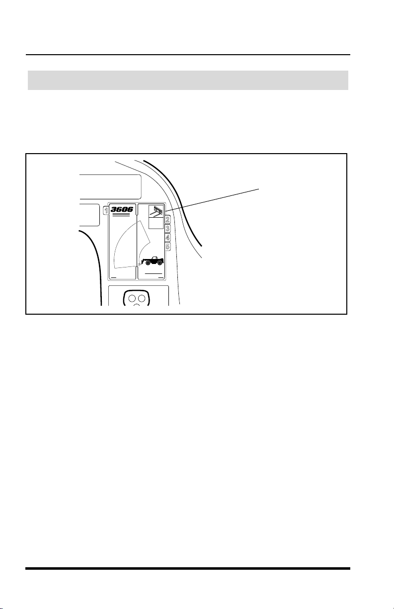
Operation
Using the Capacity Chart
The individual capacity charts are located inside a booklet on the right side
of the operator’s compartment. Capacity charts are provided to assist the
operator in determining how far in front, how high and at what angle a
specific load can be safely handled with this vehicle.
Capacity
Chart
Booklet
OS1680
Figure 44
The vehicle is equipped with two indicators that will assist the operator in
determining how to accurately use the capacity chart. These indicators are:
boom extend stripes (Figure 45)
•
boom angle indicator (Figure 46)
•
As the boom is extended, boom extend stripes become visible on the left
side of the intermediate boom. These stripes indicate the point of boom
extension and correspond to the capacity chart. For example, when the
boom extend “B” stripe first appears, the boom is at the point of boom
extension corresponding to an arc of line “B” on the capacity chart.
68
3606 Rev 11/99

Operation
Operation
3606 Rev 11/99
69
Figure 45
The boom angle indicator, located on the left side of the outer boom,
indicates the angle of the boom and also corresponds with the angles
indicated on the capacity chart.
Figure 46
To accurately use the capacity chart, the operator must first determine three
important things:
1. Weight
of the load being lifted.
2. Height
of the structure where the load is to be placed.
3. Distance
where the load will ultimately be placed in front of the front
tires.
A B
OS1710
Boom Extend Stripes
Intermediate
Boom
OS0240
Boom Angle Indicator
Outer Boom
Boom Extend Stripes
A B
Intermediate
Boom
Figure 45
The boom angle indicator, located on the left side of the outer boom,
indicates the angle of the boom and also corresponds with the angles
indicated on the capacity chart.
Boom Angle Indicator
Outer Boom
OS1710
OS0240
Figure 46
To accurately use the capacity chart, the operator must first determine three
important things:
1. Weight
2. Height
3. Distance
tires.
3606 Rev 11/99
of the load being lifted.
of the structure where the load is to be placed.
where the load will ultimately be placed in front of the front
69

Operation
Reading the Standard Capacity Chart
Example:
1. The operator has placed the load onto the forks, fully retracted the
boom, positioned the vehicle perpendicular to the structure and leveled the vehicle.
2. The operator determines that:
The weight
•
The height
•
feet from ground level,
The distance
•
the vehicle is 8 feet from the front of the tires.
3. After applying the height of the structure and the distance of load
placement away from the vehicle to the capacity chart (Figure 47),
the operator knows that it will be safe to place the load if the boom
extend stripe for zone “D” has not started to show and the boom
angle indicator reading does not go below approximately 50°.
This condition is however, a maximum limit for this weight, height and
distance away from the vehicle. The operator should move the vehicle
closer to the structure to assure that the vehicle will not exceed the
maximum limits for placing the load.
of the load is 6,500 pounds,
of the structure the load is to be placed upon is 24
where the load will ultimately be placed in front of
WARNING
DO NOT
excess of those shown on the capacity chart may cause vehicle tipover,
loss of load or structural damage which could result in death or serious
injury.
70
exceed rated capacities! Any attempt to lift or carry loads in
3606 Rev 11/99

Standard Carriage Capacity Chart
Operation
3606 Rev 11/99
71
Standard Carriage Capacity Chart
Figure 47
Load
Placement
Example
OS0351
Operation
3606 Rev 11/99
Figure 47
Load
Placement
Example
OS0351
71

Operation
Truss Boom Capacity Chart
72
OS0382
Figure 48
3606 Rev 11/99

Swing Carriage Capacity Chart
Operation
3606 Rev 11/99
73
Swing Carriage Capacity Chart
Figure 49
OS1661
Operation
3606 Rev 11/99
Figure 49
OS1661
73
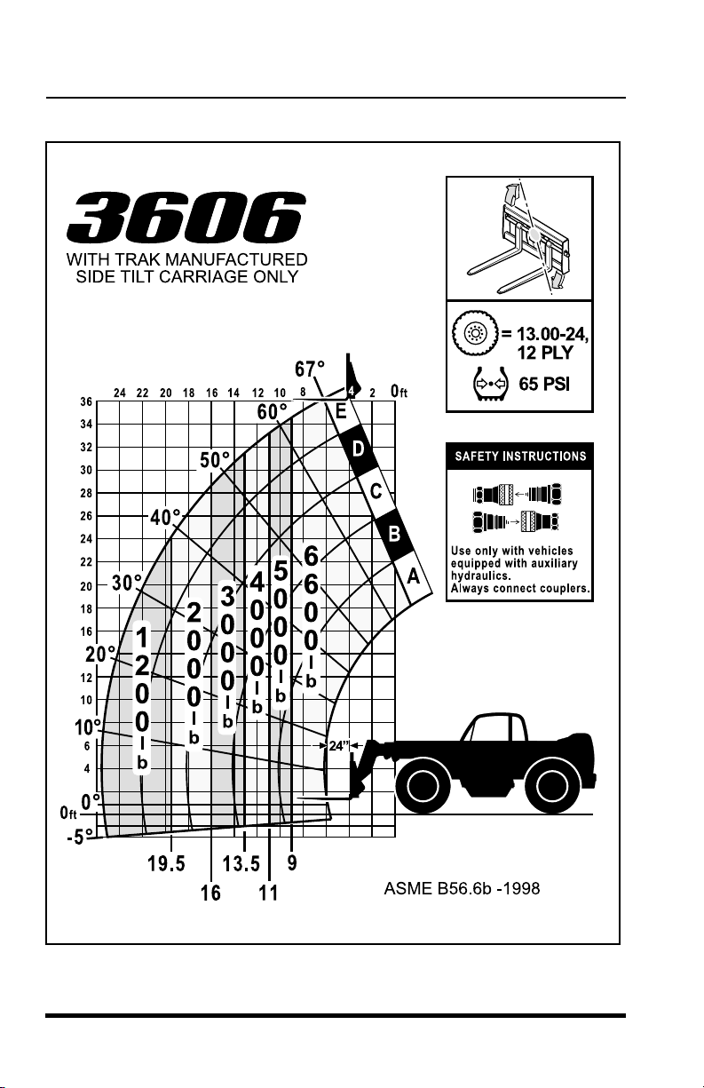
Operation
Side Tilt Carriage Capacity Chart
74
OS1670
Figure 50
3606 Rev 11/99

Operation
Operation
3606 Rev 11/99
75
All approved forks for this vehicle are marked with a maximum load capacity
rating. This rating is stamped on the left edge of the fork just below the fork
pivot shaft (Figure 51). The rating is listed in U.S. pounds and based upon a
24” (610 mm) load center. This rating specifies the maximum load capacity
that the individual fork can safely carry at a maximum load center of 24”
(610 mm). Since forks are always used in multiples, the total rating of any
combination of forks will be the sum of their rated capacity. Other than block
forks, all forks should be used in matched pairs. Block forks should be used
in matched sets.
Figure 51
Fork Rating
WARNING
DO NOT
exceed the total rated capacity of the specific pair of forks
being used. Forks can break causing loss of load and possible death or
serious injury to the operator or personnel in the area. If the total rated
capacity of the forks exceeds
the capacity of the vehicle, the vehicle
capacity should not be exceeded.
4000 x 24
4000 x 24
24 in.
(610mm)
OS0390
Stamped
Load
Rating
Load
Center
Fork Rating
All approved forks for this vehicle are marked with a maximum load capacity
rating. This rating is stamped on the left edge of the fork just below the fork
pivot shaft (Figure 51). The rating is listed in U.S. pounds and based upon a
24” (610 mm) load center. This rating specifies the maximum load capacity
that the individual fork can safely carry at a maximum load center of 24”
(610 mm). Since forks are always used in multiples, the total rating of any
combination of forks will be the sum of their rated capacity. Other than block
forks, all forks should be used in matched pairs. Block forks should be used
in matched sets.
Stamped
Load
Rating
24 in.
(610mm)
Load
Center
4000 x 24
4000 x 24
OS0390
Figure 51
WARNING
exceed the total rated capacity of the specific pair of forks
DO NOT
being used. Forks can break causing loss of load and possible death or
serious injury to the operator or personnel in the area. If the total rated
capacity of the forks exceeds
capacity should not be exceeded.
3606 Rev 11/99
the capacity of the vehicle, the vehicle
75

Operation
The maximum load capacity for this vehicle is 6,600 pounds (2994 Kg). The
matched pair or set of forks used on this vehicle should have total load
ratings which equal or exceed 6,600 pounds (2994 Kg). When the load
rating of the vehicle differs from the load capacity of the forks, the lower
value becomes the overall load capacity.
How To Pick, Carry & Place A Load
To pick a load, tilt the carriage forward so the forks hang freely on the fork
shaft. Move the forks inward or outward on the fork shaft so that they are
aligned with the openings in the pallet. Tilt the carriage back and extend the
boom slowly so the forks slide into the openings in the pallet. Raise the
boom so that the load is lifted.
To carry a load, position the boom so that the load is as low as possible and
the travel area is visible to the operator.
Before placing the load, use the capacity chart to determine safe boom
extension range for the applicable load. To place a load, align the forks at
the level the load is to be placed and then extend the boom slowly until the
load is just above the area where it is to be placed. Lower the boom until the
pallet rests in position and the forks are free to retract.
Elevating Personnel
This vehicle is designed to lift and transport materials and in many cases
should not be used to elevate personnel. Only equipment designed and
approved for elevating personnel should be used.
If the vehicle must be used to elevate personnel, use only an approved
work platform. When using a work platform, the following precautions must
be taken:
WARNING
Use only an approved work platform to lift or lower personnel.
drive the vehicle with the work platform in a raised position or
Never
with personnel on board, even for a short distance.
76
3606 Rev 11/99

Operation
Operation
3606 Rev 11/99
77
Preperation and Set-up
1. Make sure that the work platform is securely attached to the quick
attach or forks. Follow the platform manufacturer’s instructions.
2. Make sure the platform, carriage and forks are secured to prevent
them from pivoting from side to side.
3. Ensure the vehicle has a firm footing and is level.
4. Place the travel select lever in (N) NEUTRAL.
5. Engage the parking brake switch. Blocking the wheels is also rec-
ommended.
6. Level the platform in both the side to side and front to back direc-
tions before use.
Elevating Personnel
1. Make sure there are no overhead obstructions or electrical wires
above the platform before lifting.
2. A trained telescopic handler must operate the controls from the
operators compartment and must remain with the vehicle at all
times. Using extreme caution, lift and lower personnel smoothly and
only at their request. The operator should move the platform up in
down only in response to instruction from personnel on the plat-
form.
WARNING
Never
tilt the platform forward or rearward when elevating with
personnel aboard. Serious injury or death could result.
DANGER
Never
operate this or any equipment in an area in which overhead
power lines, overhead or underground cables, or power sources exist
without first requesting that the appropriate power company or utility
company de-energize the lines or take other suitable precautions.
Preperation and Set-up
1. Make sure that the work platform is securely attached to the quick
attach or forks. Follow the platform manufacturer’s instructions.
2. Make sure the platform, carriage and forks are secured to prevent
them from pivoting from side to side.
3. Ensure the vehicle has a firm footing and is level.
4. Place the travel select lever in (N) NEUTRAL.
5. Engage the parking brake switch. Blocking the wheels is also recommended.
6. Level the platform in both the side to side and front to back directions before use.
WARNING
tilt the platform forward or rearward when elevating with
Never
personnel aboard. Serious injury or death could result.
DANGER
operate this or any equipment in an area in which overhead
Never
power lines, overhead or underground cables, or power sources exist
without first requesting that the appropriate power company or utility
company de-energize the lines or take other suitable precautions.
Elevating Personnel
1. Make sure there are no overhead obstructions or electrical wires
above the platform before lifting.
2. A trained telescopic handler must operate the controls from the
operators compartment and must remain with the vehicle at all
times. Using extreme caution, lift and lower personnel smoothly and
only at their request. The operator should move the platform up in
down only in response to instruction from personnel on the platform.
3606 Rev 11/99
77

Operation
3. Always position the platform in the travel position (approximately
one foot above ground level) before moving the vehicle.
IMPORTANT!
Make sure that required restraining equipment such as
railings, chains, cable, body belts with lanyards, etc. are in place and
properly used. Never use railings, planks, ladders, etc. on the platform for
the purpose of achieving additional reach or height.
Capacity Limitations
The combined mass (weight in pounds) of the platform, load and personnel
shall not exceed one-third
position indicated on the capacity chart. Refer to “Using the Capacity Chart”
on page 68.
(33%) of the capacity of the related load center
Using Other Attachments
Numerous attachments, marketed by
vehicle. The capacity charts attached to this vehicles dash are to be used
with
Sky Trak
attachments must only be used on vehicles equipped with auxiliary
hydraulics.
approved attachments only. Hydraulically powered
Sky Trak
IMPORTANT! This vehicle is intended for the function of lifting
are available for this
only. This
vehicle is not designed to PULL, TOW or DRAG other objects.
Sky Trak
to the design, manufacture or fitness for use with this vehicle of any third
party source attachment. This vehicle is not intended to be used and should
not be used with an attachment that would alter the center of gravity or
stability of this vehicle.
attachment that would alter the center of gravity stability.
IMPORTANT!
Following is a list of some of the attachments available through
this vehicle model:
• 48” Standard Carriage
• 60” Standard Carriage
• 72” Standard Carriage
• 1-1/4 Cubic Yard Bucket
The standard capacity chart (Figure 47) is applicable for the above listed
attachments.
makes no representations or warranties, expressed or implied, as
Sky Trak
assumes no liability for any third party
DO NOT use unapproved attachments.
Sky Trak
for
78
3606 Rev 11/99

Operation
Operation
3606 Rev 11/99
79
The attachments listed below are supplied with their own individual capacity
chart:
• 12’ Truss Boom
• 48, 60 & 72” Side Tilt Carriage
• 52 & 72” Swing Carriage
Hydraulically actuated attachments also have a maximum hydraulic
pressure rating. Ensure that the maximum rated hydraulic pressure of the
attachment is equal to or slightly greater than 3,500 psi (241,2 bar), which is
the maximum pressure of the vehicles auxiliary hydraulics at the quick
disconnect couplers.
1. Bring the vehicle to a complete stop using the service brakes.
2. Park the vehicle on level ground.
3. Place the travel select lever in (N) NEUTRAL and engage the park-
ing brake switch.
4. Lower the boom and ground the carriage.
5. Turn the ignition key to the OFF position and remove the key.
Shut-Off
WARNING
To prevent personal injury or death, be certain to lower the boom, shut
off the engine and engage the parking brake switch prior to exiting the
vehicle.
The attachments listed below are supplied with their own individual capacity
chart:
• 12’ Truss Boom
• 48, 60 & 72” Side Tilt Carriage
• 52 & 72” Swing Carriage
Hydraulically actuated attachments also have a maximum hydraulic
pressure rating. Ensure that the maximum rated hydraulic pressure of the
attachment is equal to or slightly greater than 3,500 psi (241,2 bar), which is
the maximum pressure of the vehicles auxiliary hydraulics at the quick
disconnect couplers.
Shut-Off
1. Bring the vehicle to a complete stop using the service brakes.
2. Park the vehicle on level ground.
WARNING
To prevent personal injury or death, be certain to lower the boom, shut
off the engine and engage the parking brake switch prior to exiting the
vehicle.
3. Place the travel select lever in (N) NEUTRAL and engage the parking brake switch.
4. Lower the boom and ground the carriage.
5. Turn the ignition key to the OFF position and remove the key.
3606 Rev 11/99
79

Operation
80
3606 Rev 11/99

Accident Prevention Tags
Accident Prevention Tags
3606 Rev 11/99
81
Accident Prevention Tags
OS2180
Accident Prevention Tags
3606 Rev 11/99
OS2180
81

Accident Prevention Tags
82
OS2180
3606 Rev 11/99

Emergency Operations
Emergency Operations
3606 Rev 11/99
83
Emergency Operations
Towing a disabled vehicle should only be attempted after exhausting all
other options. Every effort should be made to repair the vehicle, and move it
under its own power before using the following emergency towing
procedures.
To prepare the vehicle for towing, the two spring applied parking brake
mechanisms must be disabled at the front axle. This will allow the front
wheels to turn freely during emergency towing.
IMPORTANT! After the vehicle has been towed to a secure location, it is
extremely important
that the parking brake be re-activated. Follow these
procedures carefully
from start to finish. Consult your local Sky Trak
Distributor or the
Sky Trak
Service Department if you are unsure about any
part of this procedure or for specific instructions for your particular situation.
Disabling the Parking Brake
1. Place an accident prevention tag on both the ignition key and the
steering wheel (Figure 52).
Figure 52
Towing a Disabled Vehicle
WARNING
BLOCK ALL FOUR WHEELS.
Failure to do so could result in death or
serious injury from vehicle roll away.
DANGER
DANGER
OS1520
Accident
Prevention
Tags
Emergency Operations
Towing a Disabled Vehicle
Towing a disabled vehicle should only be attempted after exhausting all
other options. Every effort should be made to repair the vehicle, and move it
under its own power before using the following emergency towing
procedures.
To prepare the vehicle for towing, the two spring applied parking brake
mechanisms must be disabled at the front axle. This will allow the front
wheels to turn freely during emergency towing.
IMPORTANT! After the vehicle has been towed to a secure location, it is
extremely important
procedures carefully
Distributor or the
part of this procedure or for specific instructions for your particular situation.
Disabling the Parking Brake
1. Place an accident prevention tag on both the ignition key and the
steering wheel (Figure 52).
that the parking brake be re-activated. Follow these
from start to finish. Consult your local Sky Trak
Sky Trak
Service Department if you are unsure about any
DANGER
WARNING
BLOCK ALL FOUR WHEELS.
serious injury from vehicle roll away.
3606 Rev 11/99
DANGER
Accident
Prevention
Tags
Figure 52
Failure to do so could result in death or
OS1520
83

Emergency Operations
2.
Block all four wheels
to prevent the vehicle from moving once the
parking brake is disabled.
3. Position the towing vehicle in place. Attach any chains needed to
secure the disabled vehicle.
4. An 8mm allen head socket and torque wrench will be needed to
properly disable the parking brakes. Scribe a line on the socket so
you can accurately count the number of turns each bolt makes as
you perform the procedure.
5. Crawl under the front axle and locate the six brake release bolts
(three bolts per side) at the base of the front axle (Figure 53). Clean
the six bolt recesses of any dirt or debris.
One of the Six
Brake Release Bolts
Located in the Front Axle
EARLY PRODUCTION CURRENT PRODUCTION
One of the Six
Brake Release Bolts
Located in the Front Axle
Figure 53
6. Alternately turn brake release bolts A, B & C inward (clockwise)
until you begin to feel resistance (Figure 54). This will take approximately two or three turns.
7. Using a torque wrench, alternately turn bolts A, B & C inward 1/2
turn until a torque of 22 lb/ft (30 Nm) is reached.
8. Again, using the torque wrench, alternately turn bolts A, B & C
inward until a minimum torque of 30 lb/ft (41Nm) is reached. This
will take approximately 1/2 turn. Do not exceed 50 lb/ft (68 Nm).
84
OS2200
3606 Rev 11/99

Turn Clockwise to
Emergency Operations
3606 Rev 11/99
85
Figure 54
9. Crawl out from under the vehicle and clear the area of any unnec-
essary personnel.
10. Before removing the blocking from each of the four tires, have
someone depress and hold the service brake. Carefully remove the
blocking from each of the four tires.
11. Tow the vehicle to a secure location.
12.
Block all four wheels and continue following the procedures.
Re-activating the Parking Brakes
WARNING
BLOCK ALL FOUR WHEELS.
Failure to do so could result in death or
serious injury from vehicle roll away.
LEFTSIDE CROSS SECTION
OF FRONT AXLE
FRONT
LEFTSIDE CROSS SECTION
OF FRONT AXLE
A
C
B
A
C
B
FRONT
OS2210
Brake
Release
Bolt
Steering
Cylinder
(Ref.)
Turn Clockwise to
Release Brake
EARLY PRODUCTION
CURRENT PRODUCTION
Brake
Release
Bolt
Steering
Cylinder
(Ref.)
Turn Clockwise to
Release Brake
Release Brake
Brake
Release
Bolt
Emergency Operations
A
C
LEFTSIDE CROSS SECTION
OF FRONT AXLE
EARLY PRODUCTION
Steering
Cylinder
(Ref.)
FRONT
B
Turn Clockwise to
Release Brake
C
Brake
Release
Bolt
CURRENT PRODUCTION
9. Crawl out from under the vehicle and clear the area of any unnecessary personnel.
10. Before removing the blocking from each of the four tires, have
someone depress and hold the service brake. Carefully remove the
blocking from each of the four tires.
11. Tow the vehicle to a secure location.
12.
Block all four wheels and continue following the procedures.
Re-activating the Parking Brakes
LEFTSIDE CROSS SECTION
Figure 54
A
OF FRONT AXLE
B
Steering
Cylinder
(Ref.)
FRONT
OS2210
WARNING
BLOCK ALL FOUR WHEELS.
serious injury from vehicle roll away.
3606 Rev 11/99
Failure to do so could result in death or
85

Emergency Operations
13. After you have blocked all four wheels, crawl under the front axle.
Using the torque wrench, alternately turn brake release bolts A, B &
C outward (counterclockwise) 1/2 turn until the torque drops to
22 lb/ft (30 Nm).
14. Again, alternately turn brake release bolts A, B & C outward (counterclockwise) 1/2 turn until the torque drops off sharply.
15. Alternately turn the brake release bolts A, B & C outward (counterclockwise) until you feel the bolt flange begin to press against the
snap ring. Turn the bolt inward 1/4 turn.
16. The parking brakes should now be re-activated and the front
wheels are locked. Remove the blocking from the four tires.
17. Verify that the parking brake works.
18. Remove any accident prevention tags from the vehicle.
Turn
Counterclockwise
To Activate Brake
Brake
Release
Bolt
Turn
Counterclockwise
To Activate Brake
Brake
Release
Bolt
A
Snap
Ring
EARLY PRODUCTION
C
LEFTSIDE CROSS SECTION
OF FRONT AXLE
A
Snap
Ring
CURRENT PRODUCTION
C
LEFTSIDE CROSS SECTION
OF FRONT AXLE
Figure 55
Steering
Cylinder
(Ref.)
FRONT
B
Steering
Cylinder
(Ref.)
FRONT
B
OS2220
86
3606 Rev 11/99

Emergency Operations
Emergency Operations
3606 Rev 11/99
87
This section discusses emergency boom lowering procedures:
Part I In case of loss of engine power or hydraulic pump failure.
Part II
In case of hydraulic line failure.
Part I
Loss of Engine Power or Hydraulic Pump Failure
IMPORTANT! In the event of total loss of engine power or hydraulic pump
failure with an elevated load, the situation must be properly evaluated and
dealt with on an individual basis. Contact your local Sky Trak Distributor or
the
Sky Trak
Service Department at (262) 268-8959 for specific instructions
for your particular situation.
In any event, the vehicle should be secured until the situation has been
properly evaluated. Secure the vehicle by following the procedures below:
1. Clear the area around the vehicle of all personnel.
2. Block all four wheels.
3. Section off a large area under the boom with string or tape to
restrict any personnel from entering this potentially dangerous area.
4. Temporarily block up or support the outer boom so it cannot be low-
ered.
5. If the load is in a position where it can be removed safely, com-
pletely remove the load from the carriage and/or attachment, other-
wise leave the load in place.
6. Place an accident prevention tag on both the ignition switch and
steering wheel. See page 81-82 for accident prevention tags. If you
do not have a safety tag, tape over the ignition switch.
Emergency Boom Lowering
WARNING
DO NOT
get under a raised boom unless the boom is blocked up.
Always block the boom before
doing any servicing that requires the
boom to be up.
Emergency Boom Lowering
This section discusses emergency boom lowering procedures:
Part I In case of loss of engine power or hydraulic pump failure.
Part II
In case of hydraulic line failure.
Part I
Loss of Engine Power or Hydraulic Pump Failure
IMPORTANT! In the event of total loss of engine power or hydraulic pump
failure with an elevated load, the situation must be properly evaluated and
dealt with on an individual basis. Contact your local Sky Trak Distributor or
Sky Trak
the
for your particular situation.
In any event, the vehicle should be secured until the situation has been
properly evaluated. Secure the vehicle by following the procedures below:
1. Clear the area around the vehicle of all personnel.
2. Block all four wheels.
3. Section off a large area under the boom with string or tape to
Service Department at (262) 268-8959 for specific instructions
restrict any personnel from entering this potentially dangerous area.
WARNING
get under a raised boom unless the boom is blocked up.
DO NOT
Always block the boom before
boom to be up.
3606 Rev 11/99
doing any servicing that requires the
4. Temporarily block up or support the outer boom so it cannot be lowered.
5. If the load is in a position where it can be removed safely, completely remove the load from the carriage and/or attachment, otherwise leave the load in place.
6. Place an accident prevention tag on both the ignition switch and
steering wheel. See page 81-82 for accident prevention tags. If you
do not have a safety tag, tape over the ignition switch.
87

Emergency Operations
Part II - Hydraulic Line Failure
In case of hydraulic line failure there are step by step procedures available
to assist you in safely retracting and then lowering the boom. Read Part II
from start to finish before performing any of these procedures so you fully
understand the process and the danger involved. If you are unsure about
any part of these procedures contact your local
Sky Trak
Service Department.
Sky Trak
Every attempt should be made to repair the hydraulic line failure and to
retract and then lower the boom in its normal fashion. We realize this is not
always possible. Step by step procedures also available when the boom
must be retracted and lowered immediately and replacement parts are not
available. Only resort to these steps (STEPS 3 & 4) when absolutely
necessary.
IMPORTANT!
Be aware that the boom must be first retracted and then
lowered to avoid vehicle tipover.
Distributor or the
Boom
Extend
Line
Boom Lower
Line (Lift
Cylinder to
Bulkhead)
Bulkhead
(Ref.)
Boom Lower
Line (Bulk-
head to
Control
Valve)
Boom
Retract
Line
Boom Lift
Line (Lift
Cylinder to
Bulkhead)
Boom Lift
Line (Bulk-
head to
Control
Valve)
Control
Valve
(Ref.)
OS0430
Figure 56
88
3606 Rev 11/99

Emergency Operations
Emergency Operations
3606 Rev 11/99
89
In any case of hydraulic line failure, it is critical to correctly identify which
hydraulic line has failed. Identify the hydraulic line that has failed (Figure 56)
and use the table below to determine which Step to follow to retract and
lower the boom.
HYDRAULIC
LINE
THAT
FAILED
FOLLOW
THIS
STEP
IF PARTS
ARE
AVAILABLE
STEP 1
STEP 1
BOOM LIFT LINE
(LIFT CYLINDER
TO BULKHEAD)
BOOM
EXTEND
LINE
BOOM
RETRACT
LINE
STEP 1
STEP 1
STEP 1
STEP 1
BOOM LIFT LINE
(BULKHEAD TO
CONTROL VALVE)
BOOM LOWER LINE
(LIFT CYLINDER TO
BULKHEAD)
BOOM LOWER LINE
(BULKHEAD TO
CONTROL VALVE)
STEP 2
STEP 2
STEP 2
FOLLOW
THIS
STEP
IF PARTS
ARE NOT
AVAILABLE
NORMAL STEPS
FOLLOW THIS
STEP AS A
LAST RESORT
STEP 3
STEP 3
STEP 4
EMERGENCY STEPS
In any case of hydraulic line failure, it is critical to correctly identify which
hydraulic line has failed. Identify the hydraulic line that has failed (Figure 56)
and use the table below to determine which Step to follow to retract and
lower the boom.
EMERGENCY STEPS
FOLLOW THIS
STEP AS A
LAST RESORT
STEP 3
HYDRAULIC
LINE
THAT
FAILED
BOOM LIFT LINE
(LIFT CYLINDER
TO BULKHEAD)
BOOM LIFT LINE
(BULKHEAD TO
CONTROL VALVE)
BOOM LOWER LINE
(LIFT CYLINDER TO
BULKHEAD)
NORMAL STEPS
FOLLOW
THIS
STEP
IF PARTS
ARE
AVAILABLE
STEP 1
STEP 1
STEP 1
FOLLOW
IF PARTS
ARE NOT
AVAILABLE
THIS
STEP
STEP 2
STEP 2
BOOM LOWER LINE
(BULKHEAD TO
CONTROL VALVE)
BOOM
EXTEND
LINE
BOOM
RETRACT
LINE
3606 Rev 11/99
STEP 1
STEP 1
STEP 1
STEP 2
STEP 3
STEP 4
89

Emergency Operations
STEP 1
1. Clear the area of any unneccessary personnel.
2. Block all four wheels.
WARNING
DO NOT
Always block the boom before
boom to be up.
get under a raised boom unless the boom is blocked up.
doing any servicing that requires the
3. If the load is in a position where it can be removed safely, completely remove the load from the carriage and/or attachment, otherwise leave the load in place.
4. Temporarily block up or support the outer boom.
WARNING
Wear protective clothing and proper eye protection when working with
or around hydraulic oil. Wait for hydraulic oil to cool before attempting to
repair the failure. Hot hydraulic oil can cause severe burns and other
serious injury.
5. Replace the failed hydraulic line with a new part (Figure 57).
6. Check the hydraulic oil level, add oil if needed.
7. Remove the blocking or support from the outer boom.
8. Return to the cab, fasten your seat belt and start the engine.
9. Tilt the carriage and/or attachment upward if necessary for clearance before retracting the boom.
10. Slowly retract the boom.
11. Slowly lower the boom and ground the carriage and/or attachment.
12. Shut off the engine.
90
3606 Rev 11/99

Boom
Emergency Operations
3606 Rev 11/99
91
Figure 57
13. Completely remove the load from the carriage and/or attachment if
you haven’t already done so.
14. Return to the cab, fasten your seat belt and start the engine.
15. Cycle the lift and extend cylinders several times to bleed air from
the system. Check for leaks.
16. Recheck the hydraulic oil level. Add oil if necessary.
OS0430
Boom
Retract
Line
Boom
Extend
Line
Bulkhead
(Ref.)
Control
Valve
(Ref.)
Boom Lift
Line (Lift
Cylinder to
Bulkhead)
Boom Lift
Line (Bulk-
head to
Control
Valve)
Boom Lower
Line (Lift
Cylinder to
Bulkhead)
Boom
Lower
Line
(Bulkhead
to Control
Valve)
Extend
Line
Boom Lower
Line (Lift
Cylinder to
Bulkhead)
Bulkhead
(Ref.)
Boom
Lower
Line
(Bulkhead
to Control
Valve)
Emergency Operations
Boom
Retract
Line
Boom Lift
Line (Lift
Cylinder to
Bulkhead)
Boom Lift
Line (Bulk-
head to
Control
Valve)
Control
Valve
(Ref.)
OS0430
Figure 57
13. Completely remove the load from the carriage and/or attachment if
you haven’t already done so.
14. Return to the cab, fasten your seat belt and start the engine.
15. Cycle the lift and extend cylinders several times to bleed air from
the system. Check for leaks.
16. Recheck the hydraulic oil level. Add oil if necessary.
3606 Rev 11/99
91

Emergency Operations
STEP 2
USE IN CASE OF:
BOOM LIFT LINE FAILURE (Lift Cylinder to Bulkhead)
BOOM LIFT LINE FAILURE (Bulkhead to Control Valve)
BOOM EXTEND LINE FAILURE
1. Clear the area of any unneccessary personnel.
2. Block all four wheels.
WARNING
Wear protective clothing and proper eye protection when working with
or around hydraulic oil. Wait for hydraulic oil to cool before attempting to
repair the failure. Hot hydraulic oil can cause severe burns and other
serious injury.
3. Place a container under the failed hose to catch any hydraulic oil
that may escape during this procedure.
4. Return to the cab, fasten your seat belt and start the engine.
5. Slowly retract the boom.
6. Slowly lower the boom and ground the carriage and/or attachment.
7. Shut off the engine.
8. Completely remove the load from the carriage and/or attachment.
9. Place a tag on both the ignition key and the steering wheel stating
that the vehicle should not be operated. See page 81-82 for tags.
10. Have the vehicle serviced immediately.
lines with new parts (Figure 58).
92
Replace any failed hydraulic
3606 Rev 11/99

Boom
Emergency Operations
3606 Rev 11/99
93
Figure 58
11. Return to the cab, fasten your seat belt and start the engine.
12. Cycle the lift cylinder several times to bleed air from the system.
Check for leaks.
13. Recheck the hydraulic oil level. Add oil if necessary.
14. Transfer any waste oil to a container with a cover and label as used
oil. Dispose of properly.
OS0430
Boom Lift
Line (Lift
Cylinder to
Bulkhead)
Bulkhead
(Ref.)
Boom Lift
Line (Bulk-
head to
Control
Valve)
Control
Valve
(Ref.)
Boom
Extend
Line
Extend
Line
Emergency Operations
Boom Lift
Line (Lift
Cylinder to
Bulkhead)
Bulkhead
(Ref.)
Boom Lift
Line (Bulk-
head to
Control
Valve)
Control
Valve
(Ref.)
Figure 58
11. Return to the cab, fasten your seat belt and start the engine.
12. Cycle the lift cylinder several times to bleed air from the system.
Check for leaks.
13. Recheck the hydraulic oil level. Add oil if necessary.
14. Transfer any waste oil to a container with a cover and label as used
oil. Dispose of properly.
3606 Rev 11/99
OS0430
93

Emergency Operations
STEP 3
BOOM LOWER LINE FAILURE (Lift Cylinder to Bulkhead)
BOOM LOWER LINE FAILURE (Bulkhead to Control Valve)
1. Clear the area of any unnecessary personnel.
2. Block all four wheels.
WARNING
DO NOT
Always block the boom before
boom to be up.
get under a raised boom unless the boom is blocked up.
doing any servicing that requires the
3. Temporarily block up or support the outer boom.
4. If the load is in a position where it can be removed safely, completely remove the load from the carriage and/or attachment, otherwise leave the load in place.
5. Place a 10 gallon (37,85 liter) container under the vehicle to catch
any hydraulic oil that will escape during this procedure.
WARNING
Wear protective clothing and proper eye protection when working with
or around hydraulic oil. Wait for hydraulic oil to cool before attempting to
repair the failure. Hot hydraulic oil can cause severe burns and other
serious injury.
6. Remove the faulty boom lower line (Figure 59).
7. Temporarily remove the adjacent boom raise line on the opposite
side of the bulkhead. This line can then be used in an emergency
situation to lower the boom.
8. Reattach this line where the faulty boom lower line was previously
(Figure 60).
94
3606 Rev 11/99

Faulty
Emergency Operations
3606 Rev 11/99
95
Figure 59
Figure 60
IMPORTANT!
Have the vehicle serviced and hoses replaced as soon as
the boom has been lowered and the vehicle is in a secure location.
OS2160
Bulkhead
(Ref.)
Faulty
Line
Removed
Faulty Line
Removed
OS2170
Bulkhead
(Ref.)
Boom
Lift
Line
Boom
Lift
Line
Line
Removed
Bulkhead
(Ref.)
Figure 59
Bulkhead
(Ref.)
Emergency Operations
Faulty Line
Removed
OS2160
Boom
Lift
Line
Boom
Lift
Line
Figure 60
IMPORTANT!
the boom has been lowered and the vehicle is in a secure location.
3606 Rev 11/99
Have the vehicle serviced and hoses replaced as soon as
OS2170
95

Emergency Operations
9. Reattach the faulty hose and direct the line so any oil that escapes
will be caught by the container.
10. Close the rear cover.
11. Check the hydraulic oil level and add oil if needed.
12. Remove the blocking or support from the outer boom.
13. Return to the cab, fasten your seat belt and start the engine.
14. Tilt the carriage and/or attachment upward if necessary for clearance before retracting the boom.
15.
Slowly
16.
Slowly
17. Completely remove the load from the carriage and/or attachment if
you haven’t already done so.
18.
Have the vehicle serviced immediately.
19. Replace any faulty hydraulic lines.
20. Return to the cab, fasten your seat belt and start the engine.
21. Cycle the lift cylinder several times to bleed air from the system.
Check for leaks.
22. Transfer the waste oil to a container with a cover and label as used
oil. Dispose of properly.
23. Recheck the hydraulic oil level. Add oil if necessary.
retract the boom.
lower the boom and ground the carriage.
96
3606 Rev 11/99

Emergency Operations
Emergency Operations
3606 Rev 11/99
97
BOOM RETRACT LINE FAILURE
1. Clear the area of any unnecessary personnel.
2. Block all four wheels.
3. If the load is in a position where it can be removed safely, com-
pletely remove the load from the carriage and/or attachment, other-
wise leave the load in place.
4. Place a 10 gallon (37,85 liter) container under the vehicle to catch
any hydraulic oil that will escape during this procedure.
STEP 4
WARNING
DO NOT
get under a raised boom unless the boom is blocked up.
Always block the boom before
doing any servicing that requires the
boom to be up.
WARNING
Wear protective clothing and proper eye protection when working with
or around hydraulic oil. Wait for hydraulic oil to cool before attempting to
repair the failure. Hot hydraulic oil can cause severe burns and other
serious injury.
STEP 4
BOOM RETRACT LINE FAILURE
1. Clear the area of any unnecessary personnel.
2. Block all four wheels.
WARNING
get under a raised boom unless the boom is blocked up.
DO NOT
Always block the boom before
boom to be up.
doing any servicing that requires the
3. If the load is in a position where it can be removed safely, completely remove the load from the carriage and/or attachment, otherwise leave the load in place.
4. Place a 10 gallon (37,85 liter) container under the vehicle to catch
any hydraulic oil that will escape during this procedure.
WARNING
Wear protective clothing and proper eye protection when working with
or around hydraulic oil. Wait for hydraulic oil to cool before attempting to
repair the failure. Hot hydraulic oil can cause severe burns and other
serious injury.
3606 Rev 11/99
97

Emergency Operations
5. Remove the faulty boom retract line (Figure 61).
6. Temporarily remove the adjacent boom extend line on the opposite
side of the extend cylinder. This line can then be used in an emergency situation to lower the boom.
7. Reattach this line where the faulty boom retract line was previously
(Figure 62).
IMPORTANT!
Have the vehicle serviced and hoses replaced as soon as
the boom has been lowered and the vehicle is in a secure location.
8. Reattach the faulty hose and direct the line so any oil that escapes
will be caught by the container.
9. Close the rear cover.
Base of
Extend
Cylinder
(Ref.)
Faulty
Boom
Retract
Line
Removed
Figure 61
OS1130
98
3606 Rev 11/99
 Loading...