


 Loading...
Operators and Safety Manual
Model
3606
8990298-004
November 1999
ANSI

 WARNING
Improper operation of this vehicle can cause injury or death.
Before starting the engine, do the following:
1.Read this owner/operators manual.
2.Read all the safety decals on the vehicle.
3.Clear the area of other persons.
Learn and practice safe use of vehicle controls in a safe, clear area before you operate this vehicle on a worksite.
It is your responsibility to observe applicable laws and regulations and to follow manufacturer's instructions on vehicle operation and maintenance.
CALIFORNIA
Proposition 65 Warning
Diesel Engine exhaust and some of its constituents are known to the State of California to cause cancer, birth defects and other reproductive harm.

Table of Contents
Introduction |
|
The Manual.................................... |
2 |
Replacement Parts ........................ |
2 |
Reports .......................................... |
2 |
Safety Practices |
|
Disclaimer...................................... |
3 |
Hazard Classification System........ |
3 |
New or Additional Operators ......... |
4 |
Personal Considerations ............... |
4 |
Operational Considerations ........... |
8 |
Equipment Considerations .......... |
13 |
Operation |
|
Operator Controls ........................ |
18 |
Operators Display Panel.............. |
31 |
Instruments and Indicators .......... |
36 |
Optional Controls......................... |
38 |
Pre-Operation Inspection............. |
43 |
Normal Starting............................ |
44 |
Cold Starting (Perkins) ................ |
45 |
Cold Starting (Cummins) ............. |
47 |
Jump Starting .............................. |
50 |
Refueling ..................................... |
51 |
Operating..................................... |
53 |
Using the Capacity Chart............. |
68 |
Fork Rating .................................. |
75 |
How To Pick, Carry & |
|
Place A Load ............................... |
76 |
Elevating Personnel..................... |
76 |
Using Other Attachments ............ |
78 |
Shut-Off ....................................... |
79 |
Emergency Operations |
|
Towing a Disabled Vehicle .......... |
83 |
Emergency Boom Lowering ........ |
87 |
General Maintenance |
|
Introduction ............................... |
100 |
Maintenance Schedule & |
|
Checklist.................................... |
101 |
Lubrication Points...................... |
104 |
Air Cleaner ................................ |
106 |
Opt. Closed Cab Air Filters........ |
109 |
Engine Cooling System ............. |
111 |
Engine Oil and Filter.................. |
114 |
Engine Fuel System .................. |
117 |
Engine Fan Belt......................... |
126 |
Hydraulic Oil and Filter .............. |
128 |
Transmission Oil and Filter........ |
131 |
Axle Oil ...................................... |
133 |
Wheel End Oil ........................... |
134 |
Transfer Case Oil ...................... |
136 |
Wheels and Tires ...................... |
138 |
Battery ....................................... |
139 |
Fuse & Relay Replacement....... |
142 |
Boom Chains & Wear Pads....... |
146 |
Storage...................................... |
150 |
Transport ................................... |
151 |
Specifications |
|
Fluid & Lubrication Capacities... |
152 |
Tires .......................................... |
153 |
Weights ..................................... |
154 |
Vehicle Dimensions................... |
154 |
Electrical System....................... |
155 |
Engine ....................................... |
156 |
1

Introduction
Introduction
The Manual
This Owners/Operators Manual provides the information you need to correctly operate and maintain this vehicle.
IMPORTANT! Before you operate this vehicle, read this manual completely and carefully so you will understand the instructions and the proper operation of the controls and equipment. You must comply with all Danger, Warning, and Caution notices; they are for your benefit.
All references to the right side, left side, front, or rear are given from the operator's seat looking forward.
Sky Trak International is hereinafter referred to as Sky Trak.
Replacement Parts
For easy reference when ordering replacement parts or making service inquiries on this vehicle, record its model and serial number on the back cover of this manual. The serial number and work order number are stamped into the serial number plate which is located on the front of the vehicle’s frame.
Serial |
Number |
Plate |
OS0013 |
IMPORTANT! The replacement of any part on this vehicle by anything other than a Sky Trak authorized replacement part may adversely affect the performance, durability or safety of this vehicle and may void the warranty. Sky Trak assumes no liability for unauthorized replacement parts which adversely affect the performance, durability or safety of this vehicle.
Reports
IMPORTANT! A Warranty Registration form must be filled out by the Sky Trak distributor, signed by the purchaser, and returned to Sky Trak once the product is sold and/or put into service. This report activates the warranty period, assuring that your claims during the warranty period will be processed promptly. To guarantee full warranty service, make sure your distributor has returned the business reply card of this form to Sky Trak.
2 |
3606 Rev 11/99 |

Safety Practices
Disclaimer
Sky Trak reserves the right to make changes on and to add improvements upon its products at any time without public notice or obligation. Sky Trak also reserves the right to discontinue manufacturing any product at its discretion at any time.
The information in this manual does not replace any safety rules and laws used in your area. Before operating this vehicle, learn the rules and laws for your area. Make sure the vehicle has the correct equipment according to these rules and laws.
Your safety and the safety of others in the worksite depend significantly upon your knowlege and understanding of all correct operating practices and procedures for this vehicle.
 WARNING
DO NOT modify or alter (weld, drill, etc.) any part of this vehicle without consulting Sky Trak. Modifications can weaken the structure creating a hazard that can cause injury or death.
Safety Practices
Hazard Classification System
OP0330
This safety alert symbol is used with the following signal words to attract your attention to messages found within the manual and on safety decals located on the vehicle. They are reproduced herein and pertain to proper operation and procedure messages contained throughout the manual. The message that follows the symbol contains important information about Safety. To avoid possible injury or death, carefully read and follow the messages! Be sure to fully understand the potential causes of injury or death.
Signal Word:
A distinctive word used throughout this manual that alerts the reader to the existence and relative degree of the hazard on or near the vehicle.
3606 Rev 11/99 |
3 |

Safety Practices
ON0021
The signal word “DANGER” indicates an imminently hazardous situation which, if not avoided, will result in death or serious injury.
ON0030
The signal word “WARNING” indicates a potentially hazardous situation which, if not avoided, could result in death or serious injury.
ON0010
The signal word “CAUTION” indicates a potentially hazardous situation which, if not avoided, may result in minor or moderate injury.
OS2020
The signal word “CAUTION” used without the safety alert symbol indicates a potentially hazardous situation which, if not avoided, may result in property damage
New or Additional Operators
At the time of original purchase, the purchaser of this vehicle was instructed by the seller on its safe and correct use. If this vehicle is to be used by an employee or is loaned or rented to someone other than the purchaser, make certain that the new operator reads and understands this Operators Manual before operating the vehicle.
In addition, make sure that the new operator has completed a walk-around inspection of the vehicle, is familiar with all decals and safety equipment on the vehicle, and has demonstrated the correct use of all controls.
Personal Considerations
1. Seat Belt
Always fasten the seat belt before starting the engine.
4 |
3606 Rev 11/99 |

Safety Practices
2. Clothing and Safety Gear
DO NOT wear loose clothing or jewelry that can get caught on controls or moving parts. Wear protective clothing and personal safety gear issued or called for by job conditions.
3. Dismounting
OS0023
DO NOT get off the vehicle until you:
•level the vehicle,
•ground the carriage,
•place the travel select lever in (N) NEUTRAL,
•engage the parking brake switch,
•turn the engine off, if appropriate,
•unbuckle the seat belt,
•exit the vehicle using the hand holds.
4.Chemical Hazards
A.Exhaust Fumes
Fumes from the engine exhaust can cause injury or death. DO NOT operate vehicle in an enclosed area without a ventilation system capable of routing the hazardous fumes outdoors.
B.Explosive Fuel
Engine fuel is flammable and can cause a fire and/or an explosion. Avoid danger by keeping sparks, open flames and smoking materials away from the vehicle and from fuel during refueling or when servicing the fuel system. Know where fire extinguishers are kept on the worksite and how to use them.
3606 Rev 11/99 |
5 |

Safety Practices
C.Hydraulic Fluid
DO NOT attempt to repair or tighten any hydraulic hoses or fittings while the engine is running or when the hydraulic system is under pressure. Fluid in the hydraulic system is under enough pressure that it can penetrate the skin causing serious injuries or death.
HOT HYDRAULIC FLUID WILL CAUSE SEVERE BURNS. Wait for fluid to cool down before disconnecting lines.
DO NOT use your hand to check for leaks. Use a piece of cardboard or paper to search for leaks. Wear gloves to protect hands from spraying fluid.
Hydraulic fluid can cause permanent eye injury. Wear appropriate eye protection and stop engine and relieve pressure before disconnecting lines.
If anyone is injured by or if any hydraulic fluid is injected into the skin, obtain medical attention immediately or gangrene may result.
D.Battery
The following WARNING is intended to supplement and does not replace the warnings and information provided on the battery by the battery manufacturer.
When jump starting the vehicle, carefully follow instructions found under “Jump Starting” on page 50.
- |
OS0621
Keep sparks, flames and lit cigarettes away from the battery at all times. Lead acid batteries generate explosive gases. Severe chemical burns can result from improper handling of battery electrolyte. Wear safety glasses and proper protective gear when handling batteries to prevent electrolyte from coming in contact with eyes, skin or clothing.
6 |
3606 Rev 11/99 |
Safety Practices
Battery Electrolyte First Aid:
•External Contact — Flush with water.
•Eyes — Flush with water for at least 15 minutes and get medical attention immediately.
•Internal Contact — Drink large quantities of water. Follow with Milk of Magnesia, beaten egg or vegetable oil.
Get medical attention immediately.
IMPORTANT! In case of internal contact, DO NOT give fluids that would induce vomiting!
5. Moving Parts Hazard
DO NOT place limbs near moving parts. Severing of any body part can result.
Turn off engine and wait until fan and belts stop moving before servicing.
OS0042 |
6. Lowering Boom or Falling Load Hazard
DO NOT get under a raised boom unless it is blocked up safely. Always empty the attachment of any load and block the boom up before doing any servicing that would require the boom to be raised.
NEVER allow anyone to walk or stand under the boom. A lowering boom or falling load can result in serious injury or death.
3606 Rev 11/99 |
7 |

Safety Practices
Operational Considerations
1. Preperation and Prevention
Know the location and function of all vehicle controls.
Make sure all persons are away from the vehicle and that the Travel Select Lever is in the (N) NEUTRAL position with the parking brake switch engaged before starting the engine.
Holes, obstructions, debris and other worksite hazards can cause injury or death. Always walk around and look for these and other hazards before operating the vehicle on a new worksite.
Prevent accidents when you move the vehicle around the worksite. Know the rules for movement of people and vehicles on the worksite. Follow the instructions of signals and signs.
DO NOT operate the vehicle unless:
•all safety equipment is in proper working condition,
•all covers and guards are in place, and
•all safety and instructional decals are in place and readable. (Replace all missing, illegible, or damaged decals.)
2.Clearances
Look out for and avoid other personnel, machinery and vehicles in the area. Travel with the boom fully retracted and lowered as far as possible while still maintaining enough ground clearance for conditions.
Always check boom clearances carefully before driving underneath door openings, bridges, etc.
Always check for power lines when raising the boom. Beware of overhead wires, contact with electrical power lines can result in electrocution. See “Electrocution Hazards” on page 9.
3. Underground Hazards
Know the location of all underground hazards before operating this vehicle in a new area or worksite. Electrical cables, gas and water pipes, sewer, or other underground objects can cause injury or death. Contact your local underground utility service or diggers hotline to mark all underground hazards.
8 |
3606 Rev 11/99 |
Safety Practices
4. Electrocution Hazards
NEVER operate this vehicle in an area where overhead power lines, overhead or underground cables, or other power sources may exist without first requesting that the appropriate power or utility company deenergize the lines, or take other suitable precautions.
OS0063
5. Carrying Personnel
Use only an approved work platform for lifting and lowering personnel. NEVER transport personnel in a work platform for even the shortest distance.
Serious injury or death can occur if these rules are not obeyed. Riders can fall and be crushed or run over. Avoid accidents.
For other specific precautions, see “Elevating Personnel” on page 76.
OS0072
OS0631
3606 Rev 11/99 |
9 |

Safety Practices
6. Tip Over Hazard
OS1633
MAINTAIN proper tire pressures at all times. Underpressurized tire(s) adversely affects vehicle stability. If proper tire pressures are not maintained, this vehicle can tip over. If a vehicle ever becomes unstable and starts to tip over:
•BRACE YOURSELF and STAY WITH THE VEHICLE,
•KEEP YOUR SEAT BELT FASTENED,
•HOLD ON FIRMLY and
•LEAN AWAY FROM THE POINT OF IMPACT.
Indecision and trying to escape from a tipping vehicle can result in death or serious injury.
To ensure proper vehicle stability, check all four tire pressures before operating the vehicle. Maintain proper tire pressures.
DO NOT exceed the rated lift capacity of the vehicle as structural damage and unstable conditions will result.
To ensure that the vehicle is positioned in the most stable condition before operating an attachment:
Use the sway control to level the vehicle. The vehicle is level when the frame level indicator gauge reaches (0°) zero degrees. If the vehicle cannot be leveled using the sway control, reposition the vehicle.
Keep the vehicle under control at all times. When negotiating turns, slow down and turn the steering wheel in a smooth sweeping motion. Avoid jerky turns, starts or stops. Reduce vehicle speed on rough ground and slopes.
10 |
3606 Rev 11/99 |

Safety Practices
OS0083
Travelling with the boom raised is dangerous and can cause tipover. Keep the boom as low as possible. Travel with extreme caution and at the slowest possible speed.
Swaying (frame tilt) left or right with the boom raised above horizontal is dangerous. Always use the sway control to level the vehicle before raising the boom above horizontal, with or without a load. If the vehicle cannot be leveled using sway control, reposition the vehicle.
7. Slopes
DO NOT park the vehicle on an incline and leave it unattended.
•Driving across a slope is dangerous, as unexpected changes in the slope can cause tipover. Ascend or descend slopes slowly and with caution.
•Ascend or descend slopes with the heavy end of the vehicle pointing up the slope.
NOTE: The rear of the vehicle is normally considered the heavy end unless the carriage is fully loaded. In this case the front of the vehicle is now the heavy end.
•Unloaded vehicles should be operated on all slopes with the carriage pointing down the slope.
•On all slopes, the load must be tilted back and raised only as far as necessary to clear the ground.
•When operating on a downhill slope, reduce travel speed and downshift to a low gear to permit compression braking by the engine and aid the application of the service brakes.
3606 Rev 11/99 |
11 |

Safety Practices
8. Falling Load Hazard
DO NOT exceed the total rated load capacity of the specific type fork being used. Each fork is stamped with a maximum load capacity. If the capacity is exceeded, forks may break. See “Fork Rating” on page 75.
DO NOT downshift at a high ground speed. Sudden slowing can cause the load to drop off the forks.
9. Visual Obstruction
Dust, smoke, fog, etc. can decrease vision and cause an accident. Always stop or slow the vehicle until the obstruction clears and the worksite is visible again.
10. Ventilation
Sparks from the electrical system and the engine exhaust can cause an explosion. DO NOT operate this vehicle in an area with flammable dust or vapors, unless good ventilation has removed the hazard.
Carbon monoxide fumes from the engine exhaust can cause suffocation in an enclosed area. Good ventilation is very important when operating this vehicle.
12 |
3606 Rev 11/99 |

Safety Practices
Equipment Considerations
 WARNING
DO NOT modify or alter (weld, drill, etc.) any part of this vehicle without consulting Sky Trak. Modifications can weaken the structure creating a hazard that can cause injury or death.
DO NOT by-pass or disconnect any electrical or hydraulic circuits. Consult the Sky Trak service department or your Sky Trak distributor if any circuit is malfunctioning.
DO check for frayed or cut seat belt webbing, damaged buckles or loose mounting brackets. Replace immediately if required.
ALWAYS wear a seat belt when operating the vehicle.
DO check tire pressure on all four tires. Add air if required.
DO check the condition of all four rims. Check for bent flanges and/or bead mounting areas.
DO NOT operate this vehicle unless all protective covers and guards are in place and secure. These devices are installed on the vehicle for your safety and protection.
DO check the parking brake operation. Repair immediately if required.
DO keep all non-skid surfaces clean and free of debris. Replace if worn, damaged or missing.
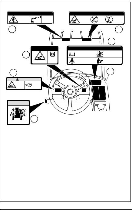
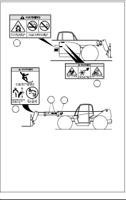
DO check the condition of important decals. Replace decals if missing, damaged or illegible. Figures 1-4 on the following pages show the proper location of the decals. Figure 1 (page 14) & Figure 2 (page 15) represent vehicles with Work Order No. 06148 thru 45611. Figure 3 (page 16) & Figure 4 (page 17) represent vehicles with Work Order No. 45612 and After. The Work Order No. is stamped into the serial number plate located on the front of the frame.
3606 Rev 11/99 |
13 |

Safety Practices
Vehicles Stamped with Work Order No. 06148 thru 45611
DANGER |
|
|
|
DANGER |
|
CONTACTING |
NEVER operate |
3 |
6 |
LOW TIRE |
MAINTAIN |
ELECTRIC |
vehicle within |
PRESSURE |
proper tire |
||
POWER LINES |
10 feet (3m) of |
can result |
pressure at |
||
can result in |
electric power |
|
|
in tipover. |
all times. |
electrocution. |
lines. |
|
|
|
|
2 |
5 |
|
|
|
4 |
|
SAFETY INSTRUCTIONS |
|
||
1 |
1. Read operator’s manual |
3. Allow no riders. |
7 |
|
before operating. |
||||
|
||||
|
|
|
|
4. Use an approved work |
|
|
|
2. Fasten seat belt. |
platform to lift or lower |
|
|
|
|
personnel. |
|
|
|
|
OS1511 |
Item |
Part Number |
Quantity |
Decal Description |
|
1 |
mold in dash |
1 |
No Riders Warning |
|
2 |
mold in dash |
1 |
Vehicle Rollaway Warning |
|
3 |
4108991 |
1 |
Electrocution Danger |
|
4 |
7134483 |
1 |
Load Chart Booklet |
|
5 |
mold in dash |
1 |
Tipover Danger - Operating |
|
6 |
4109151 |
1 |
Tipover Danger - Tire Pressure |
|
7 |
4109371 |
1 |
Safety Instructions |
|
NOTE: Many of these hazard related decals are available free of charge by calling OmniQuip Parts Worldwide at (888) 872-5123.
Figure 1
14 |
3606 Rev 11/99 |

Safety Practices
Vehicles Stamped with Work Order No. 06148 thru 45611
9
8
|
|
|
|
|
|
|
|
|
|
|
|
|
|
|
|
|
|
|
|
|
|
|
|
|
|
|
|
|
|
|
|
|
|
|
|
|
|
|
|
|
|
|
|
|
|
|
|
|
|
|
|
|
|
11 |
12 |
||||
|
|
|
|||||||||
|
|
|
|
|
|
|
|
|
|
|
|
10 
OS1256
Item |
Part Number |
Quantity |
Decal Description |
|
|
|
|
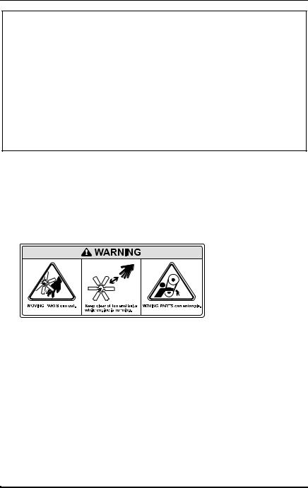
8 |
4108981 |
1 |
Moving Parts Warning |
|
|
|
|
9 |
4109021 |
1 |
Explosive Gases Warning |
|
|
|
|
10 |
4109041 |
1 |
Carrying Personnel Warning |
|
|
|
|
11 |
4108841 |
1 |
Boom Extend Stripes |
|
|
|
|
12 |
4105262 |
1 |
Boom Angle Indicator |
|
|
|
|
NOTE: All of these hazard related decals are available free of charge by calling OmniQuip Parts Worldwide at (888) 872-5123.
Figure 2
3606 Rev 11/99 |
15 |
Safety Practices
Vehicles Stamped with Work Order No. 45612 and After
 DANGER
CONTACTING |
NEVER operate |
ELECTRIC |
vehicle within |
POWER LINES |
10 feet (3m) of |
can result in |
electric power |
electrocution. |
lines. |
3
 DANGER
6 |
|
|
|
|
MAINTAIN |
|
|
proper tire |
|
LOW TIRE PRESSURE |
pressure at |
|
can result in tipover. |
all times. |
2 |
|
|
WARNING |
ALWAYS |
|
VEHICLE |
|
|
ROLLAWAY |
engage |
|
can cause |
parking |
|
death or |
brake |
|
serious |
before |
|
injury. |
dismounting. |
|
 WARNING
1
Allow no riders.
 DANGER
VEHICLE |
DO NOT |
DO NOT raise |
TIPOVER |
travel |
boom while |
can result |
with the |
on a slope |
in death or |
boom |
unless load |
serious injury. |
raised. |
is level. |
|
|
5 |
|
|
7 |
SAFETY INSTRUCTIONS |
||
1. Read operator’s manual |
|
3. Allow no riders. |
before operating. |
|
|
|
|
|
2. Fasten seat belt. |
|
4. Use an approved work |
|
platform to lift or lower |
|
|
|
personnel. |
4
OS1241
Item |
Part Number |
Quantity |
Decal Description |
|
|
|
|
1 |
mold in dash |
1 |
No Riders Warning |
|
|
|
|
2 |
mold in dash |
1 |
Vehicle Rollaway Warning |
|
|
|
|
3 |
4108991 |
1 |
Electrocution Danger |
|
|
|
|
4 |
7134483 |
1 |
Load Chart Booklet |
|
|
|
|
5 |
4109011 |
1 |
Tipover Danger - Operating |
|
|
|
|
6 |
mold in dash |
1 |
Tipover Danger - Tire Pressure |
|
|
|
|
7 |
mold in dash |
1 |
Safety Instructions |
|
|
|
|
NOTE: Many of these hazard related decals are available free of charge by calling OmniQuip Parts Worldwide at (888) 872-5123.
Figure 3
16 |
3606 Rev 11/99 |
Safety Practices
Vehicles Stamped with Work Order No. 45612 and After
9
8
|
|
|
|
|
|
|
|
|
|
|
|
|
|
|
|
|
|
|
|
|
|
|
|
|
|
|
|
|
|
|
|
|
|
|
|
|
|
|
|
|
|
|
|
|
|
|
|
|
|
|
|
|
|
11 |
12 |
||||
|
|
|
|||||||||
|
|
|
|
|
|
|
|
|
|
|
|
10 
OS1255
Item |
Part Number |
Quantity |
Decal Description |
|
|
|
|
8 |
4108981 |
2 |
Moving Parts Warning |
|
|
|
|
9 |
4109021 |
1 |
Explosive Gases Warning |
|
|
|
|
10 |
4109041 |
1 |
Carrying Personnel Warning |
|
|
|
|
11 |
4108841 |
1 |
Boom Extend Stripes |
|
|
|
|
12 |
4105262 |
1 |
Boom Angle Indicator |
|
|
|
|
NOTE: All of these hazard related decals are available free of charge by calling OmniQuip Parts Worldwide at (888) 872-5123.
Figure 4
3606 Rev 11/99 |
17 |

Operation
Operation
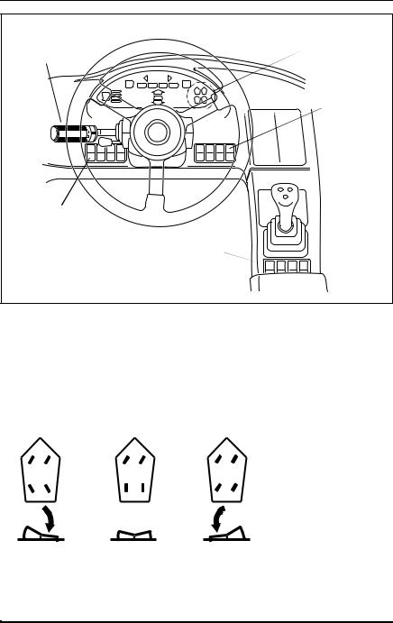
Operator Controls
Accelerator Pedal
(Figure 5)
Pressing down the accelerator pedal increases engine and hydraulic speed of the vehicle. The pedal is spring-loaded to return to idle speed.
Service Brake Pedal
(Figure 5)
Pressing down the brake pedal decreases the speed of the vehicle by applying the service brakes located in the axles. In the event of engine power loss the service brake pedal can also be used for emergency braking.
Steering Wheel
(Figure 5)
Turning the steering wheel to the left or right steers the vehicle in the corresponding direction. Any one of three steering modes are selectable. Refer to “Steering Select Switch” on page 20.
Tilt Steering Wheel Lever
(Figure 6)
To tilt the wheel, hold the steering wheel and pull the lever toward you. Move the steering wheel to a comfotable operating level, then release the lever to lock the wheel in place.
Horn Button
(Figure 5)
Pressing the button sounds the horn.
Steering |
Horn Button |
Wheel |
|
Ignition
Switch
Accelerator
Service Pedal
Brake Pedal
OS0091
Figure 5
18 |
3606 Rev 11/99 |
Operation
Steering
Wheel - Ref.
Tilt Steering
Wheel Lever
OS1120
Figure 6
Ignition Switch
(Figure 7)
Using the ignition switch key, the switch may be turned clockwise from the OFF position to the RUN, PREHEAT and START positions. The PREHEAT and START positions are spring-loaded to return to the RUN position and must be manually held in place for starting.
OFF position — The entire electrical system is shut down.
RUN position — All controls and indicators are operable.
PREHEAT position — Optional (Perkins) - Preheats air in the induction manifold for cold weather starting (see “Cold Starting” on page 45).
START position — Engages starter motor to crank the engine when the parking brake switch is engaged and the transmission is in NEUTRAL.
OFF RUN
PREHEAT
START
OF0390
Figure 7
3606 Rev 11/99 |
19 |
Operation
Travel and |
Steering |
Gear Select |
Selection |
Lever |
Indicators |
|
Attachment |
|
Tilt Mode |
|
Switch |
Parking
Brake
Switch
Steering Select Switch  (Either of two locations)
OS0403
Figure 8
Steering Select Switch
(Figure 8)
The switch has three positions:
FOUR |
FRONT |
|
|
|
|
||||||
WHEEL |
WHEEL |
CRAB |
|||||||||
STEERING |
STEERING |
STEERING |
|||||||||
|
|
|
|
|
|
|
|
|
|
|
|
|
|
|
|
|
|
|
|
|
|
|
|
OS0640
Refer to “Steering Modes” on page 59 for detailed information.
20 |
3606 Rev 11/99 |

Operation
Parking Brake Switch
(Figure 8)
The parking brake switch has two positions:
Engaged................................ |
toggle switch downward |
P |
Disengaged................................ |
toggle switch upward |
P |
OS1323 |
|
OS0121 |
|
|
The parking brake switch must be ENGAGED to permit engine starting.
The parking brake may be used to stop in an EMERGENCY situation however, use caution because the stop will be abrupt and the operator and the load may be jolted forward unexpectedly.
Attachment Tilt Mode Switch
(Figure 8)
OS2120
The attachment tilt mode switch has two positions which allow the operator to chose between Lift/Lower function and the Extend/Retract function accompanying the Attachment Tilt capability. For detailed information, see “Multi-Function Joystick Operation” starting on page 24.
3606 Rev 11/99 |
21 |
Operation
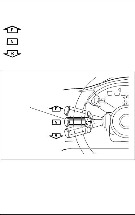
Travel Select Lever
(Figure 9)
The travel select lever has three positions to select direction of travel:
F = FORWARD |
...................................all the way UP |
N = NEUTRAL .................................... |
CENTER position |
R = REVERSE.................................... |
all the way DOWN |
OS0340
Travel
Select
Lever 
OS0130
Figure 9
To change travel selections, grasp the lever and pull it toward the steering wheel, then UP or DOWN to the desired selection.
When the travel select lever is shifted to REVERSE, the back-up alarm will automatically sound.
NOTE: The travel select lever must be in the (N) NEUTRAL position to permit engine starting.
22 |
3606 Rev 11/99 |

Operation
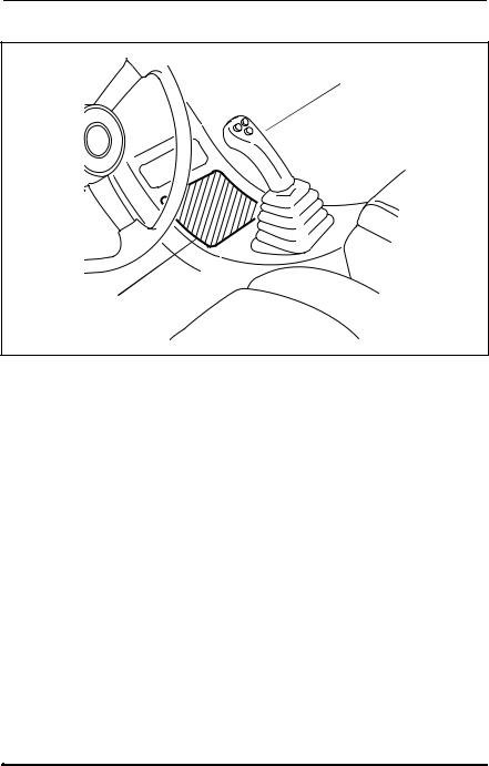
Gear Select Lever
(Figure 10)
The gear select lever has a twist grip handle with four positions. Vehicles equipped with either Cummins or Perkins turbocharged engine have four (4) forward gears and three (3) reverse. Vehicles equipped with a naturally aspirated Perkins engine have three (3) forward gears and three (3) reverse. Use first gear for highest torque and pulling power. Use higher gears for higher ground speed.
Gear
Select
Lever 
OS0141
Figure 10
3606 Rev 11/99 |
23 |
Operation
Multi-Function Joystick
(Figure 11)
Multi-Function
 Joystick
Logic Panel
OS0152
Figure 11
The joystick is equipped with four buttons that enable the joystick to operate in four specific modes. The joystick controls boom movement, attachment tilt, sway control and optional auxiliary hydraulics.
The logic panel (located in front of the joystick) will illuminate the specific mode that corresponds with the movement of the joystick and the selected buttons.
Two functions can be accomplished at the same time by moving the joystick in between quadrants. For example; in Mode 1 moving the joystick forward and to the left will lower and retract the boom simultaneously.
The speed of movement depends upon the amount of joystick movement in the corresponding direction. The overall speed of movement depends directly upon engine speed.
IMPORTANT! Be aware that joystick modes will change immediately upon depressing or releasing of any button when the joystick is in an off-center position.
24 |
3606 Rev 11/99 |
Operation
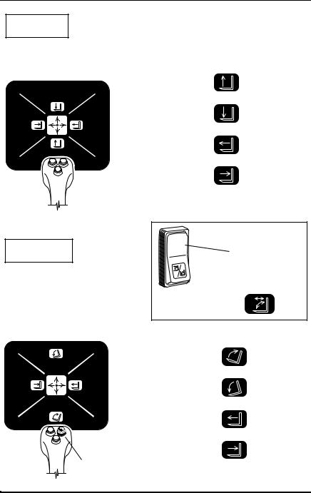
MODE 1
Boom Control (Default) |
logic panel symbol |
|
(No buttons depressed) |
|
|
|
|
|
|
Boom Lift |
move handle |
|
backward |
|
|
|
|
|
Boom Lower |
move handle |
|
forward |
|
|
|
|
|
Boom Extend |
move handle |
|
to the right |
|
|
|
|
OS2050 |
Boom Retract |
move handle |
to the left |
||
|
|
|
Attachment
Tilt Mode
MODE 2A Switch In
MODE 2A
Attachment Tilt Up/Down |
display panel symbol |
|
& Boom Extend/Retract |
||
Attachment Tilt with |
||
(Right button depressed) |
||
|
Extend & Retract |
logic panel symbol
Attachment Tilt Up ........ |
move handle |
|
backward |
||
|
||
Attachment Tilt Down.... |
move handle |
|
forward |
||
|
||
Boom Extend ................ |
move handle |
|
to the right |
||
|
||
OS2060 |
move handle |
|
Boom Retract ................ |
||
to the left |
||
Depress |
|
|
Right Button |
|
3606 Rev 11/99 |
25 |
Operation
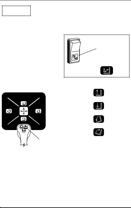
MODE 2B
Boom Lift/Lower & Attachment Tilt Up/Down
(Right button depressed)
Attachment
Tilt Mode
Switch In
MODE 2B
display panel symbol |
||
Attachment Tilt |
|
|
with Lift & Lower |
|
|
logic panel symbol |
||
Boom Lift ...................... |
move handle |
|
backward |
||
|
||
Boom Lower.................. |
move handle |
|
forward |
||
|
||
Attachment Tilt Down .... |
move handle |
|
to the right |
||
|
OS2070 |
Attachment Tilt Up ........ |
move handle |
to the left |
||
|
|
|
|
Depress |
|
|
Right Button |
|
26 |
3606 Rev 11/99 |

Operation
MODE 3
Boom Lift/Lower & Frame Sway Right/Left
(Depress left & front button simultaneously, then hold either button)
logic panel symbol
|
Boom Lift |
move handle |
|
backward |
|
|
|
|
|
Boom Lower |
move handle |
|
forward |
|
|
|
|
|
Frame Sway Right |
move handle |
|
to the right |
|
|
|
|
OS2080 |
Frame Sway Left |
move handle |
to the left |
||
|
|
Depress
Left & Front
Buttons
Simultaneously,
Then Hold
Either
Button
3606 Rev 11/99 |
27 |

Operation
MODE 4
Auxiliary Hydraulic Control - Optional
(Center button depressed)
The auxiliary hydraulic control regulates the functions of an optional attachment. Some of the optional attachments that require auxiliary hydraulics are: Side Tilt Carriage, Swing Carriage.
Depress
Center
Button
OS2090
When the joystick is moved to the left, it will provide hydraulic system pressure through the male coupling for the auxiliary attachment.
When the joystick is moved to the right, it will provide hydraulic system pressure through the female coupling for the auxiliary attachment.
The joystick will provide the following typical functions for each specified attachment listed below if they are connected properly. Operation will be reversed if incorrectly connected. Shutting the vehicle down, releasing the hydraulic pressure and reversing the disconnect couplings on the hoses that are supplied with the attachment will often correct the problem. Contact your local Sky Trak distributor or the Sky Trak service department for more information.
Side Tilt Carriage Operation |
|
• Handle right............................. |
tilt right |
• Handle left ............................... |
tilt left |
Swing Carriage Operation |
|
• Handle right............................. |
swing right |
• Handle left ............................... |
swing left |
28 |
3606 Rev 11/99 |
Loading...