


6042


SECTION CONTENTS
Model 6042 Legacy Origin 7/02
i
ã 2002 OmniQuip Textron Inc.
Section Subject Page
Section 1
Safety Practices . . . . . . . . . . . . . . . . . . . . . . . . . . . . . . . . . . . . . . . . . . . . . . . . . . . . . . . 1.1
1.1 Introduction . . . . . . . . . . . . . . . . . . . . . . . . . . . . . . . . . . . . . . . . . . . . . . . . . . . . . . . . . . 1.2
1.2 Owners/Operators Manual . . . . . . . . . . . . . . . . . . . . . . . . . . . . . . . . . . . . . . . . . . . . . . 1.2
1.3 Training Mechanics as Operators . . . . . . . . . . . . . . . . . . . . . . . . . . . . . . . . . . . . . . . . . 1.3
1.4 Safety Information . . . . . . . . . . . . . . . . . . . . . . . . . . . . . . . . . . . . . . . . . . . . . . . . . . . . . 1.3
1.5 Accident Prevention Tag Usage . . . . . . . . . . . . . . . . . . . . . . . . . . . . . . . . . . . . . . . . . . 1.4
1.6 Safety Instructions. . . . . . . . . . . . . . . . . . . . . . . . . . . . . . . . . . . . . . . . . . . . . . . . . . . . . 1.5
1.7 Emergency Exit Rear Window . . . . . . . . . . . . . . . . . . . . . . . . . . . . . . . . . . . . . . . . . . . 1.6
1.8 Hazard/Emergency Information Decals . . . . . . . . . . . . . . . . . . . . . . . . . . . . . . . . . . . . 1.7
Section 2
General Information and Specifications . . . . . . . . . . . . . . . . . . . . . . . . . . . . . . . . . . . . 2.1
2.1 6042 Component Terminology . . . . . . . . . . . . . . . . . . . . . . . . . . . . . . . . . . . . . . . . . . . 2.3
2.2 Introduction . . . . . . . . . . . . . . . . . . . . . . . . . . . . . . . . . . . . . . . . . . . . . . . . . . . . . . . . . . 2.4
2.3 Torques . . . . . . . . . . . . . . . . . . . . . . . . . . . . . . . . . . . . . . . . . . . . . . . . . . . . . . . . . . . . . 2.6
2.4 Metric Conversion Factors. . . . . . . . . . . . . . . . . . . . . . . . . . . . . . . . . . . . . . . . . . . . . . . 2.12
2.5 Specifications . . . . . . . . . . . . . . . . . . . . . . . . . . . . . . . . . . . . . . . . . . . . . . . . . . . . . . . . 2.14
2.6 Fluids, Lubricants and Capacities . . . . . . . . . . . . . . . . . . . . . . . . . . . . . . . . . . . . . . . . . 2.23
2.7 Cleaning . . . . . . . . . . . . . . . . . . . . . . . . . . . . . . . . . . . . . . . . . . . . . . . . . . . . . . . . . . . . 2.27
2.8 Replacement . . . . . . . . . . . . . . . . . . . . . . . . . . . . . . . . . . . . . . . . . . . . . . . . . . . . . . . . . 2.28
2.9 Hoses and Tubes . . . . . . . . . . . . . . . . . . . . . . . . . . . . . . . . . . . . . . . . . . . . . . . . . . . . . 2.28
2.10 Bearings . . . . . . . . . . . . . . . . . . . . . . . . . . . . . . . . . . . . . . . . . . . . . . . . . . . . . . . . . . . . 2.28
2.11 Pressure Testing and Adjustment . . . . . . . . . . . . . . . . . . . . . . . . . . . . . . . . . . . . . . . . . 2.29
2.12 After Service Startup and Checks. . . . . . . . . . . . . . . . . . . . . . . . . . . . . . . . . . . . . . . . . 2.29
Section 3
Boom . . . . . . . . . . . . . . . . . . . . . . . . . . . . . . . . . . . . . . . . . . . . . . . . . . . . . . . . . . . 3.1
3.1 Boom System Component Terminology . . . . . . . . . . . . . . . . . . . . . . . . . . . . . . . . . . . . 3.2
3.2 Boom System . . . . . . . . . . . . . . . . . . . . . . . . . . . . . . . . . . . . . . . . . . . . . . . . . . . . . . . . 3.3
3.3 Boom Assembly Maintenance. . . . . . . . . . . . . . . . . . . . . . . . . . . . . . . . . . . . . . . . . . . . 3.3
3.4 Boom Chains. . . . . . . . . . . . . . . . . . . . . . . . . . . . . . . . . . . . . . . . . . . . . . . . . . . . . . . . . 3.46
3.5 Boom Wear Pads . . . . . . . . . . . . . . . . . . . . . . . . . . . . . . . . . . . . . . . . . . . . . . . . . . . . . 3.65
3.6 Quick Attach Assembly . . . . . . . . . . . . . . . . . . . . . . . . . . . . . . . . . . . . . . . . . . . . . . . . . 3.68
3.7 Troubleshooting. . . . . . . . . . . . . . . . . . . . . . . . . . . . . . . . . . . . . . . . . . . . . . . . . . . . . . . 3.71
Section 4
Cab and Covers . . . . . . . . . . . . . . . . . . . . . . . . . . . . . . . . . . . . . . . . . . . . . . . . . . . . . . . . 4.1
4.1 Operator’s Cab and Covers Component Terminology. . . . . . . . . . . . . . . . . . . . . . . . . . 4.2
4.2 Operator’s Cab . . . . . . . . . . . . . . . . . . . . . . . . . . . . . . . . . . . . . . . . . . . . . . . . . . . . . . . 4.3
4.3 Open Cab Components . . . . . . . . . . . . . . . . . . . . . . . . . . . . . . . . . . . . . . . . . . . . . . . . 4.4
4.4 Enclosed Cab (Optional) Components . . . . . . . . . . . . . . . . . . . . . . . . . . . . . . . . . . . . . 4.20
4.5 Cab Removal. . . . . . . . . . . . . . . . . . . . . . . . . . . . . . . . . . . . . . . . . . . . . . . . . . . . . . . . . 4.26
4.6 Cab Installation . . . . . . . . . . . . . . . . . . . . . . . . . . . . . . . . . . . . . . . . . . . . . . . . . . . . . . . 4.29
4.7 Access Panels and Covers . . . . . . . . . . . . . . . . . . . . . . . . . . . . . . . . . . . . . . . . . . . . . . 4.32

Section Subject Page
ii
Model 6042 Legacy Origin 7/02
Section 5
Axles, Drive Shafts, Wheels and Tires . . . . . . . . . . . . . . . . . . . . . . . . . . . . . . . . . . . . . . 5.1
5.1 Axle, Drive Shaft and Wheel Component Terminology . . . . . . . . . . . . . . . . . . . . . . . . . 5.2
5.2 General Information . . . . . . . . . . . . . . . . . . . . . . . . . . . . . . . . . . . . . . . . . . . . . . . . . . . . 5.3
5.3 Axle Assemblies. . . . . . . . . . . . . . . . . . . . . . . . . . . . . . . . . . . . . . . . . . . . . . . . . . . . . . . 5.3
5.4 Drive Shafts . . . . . . . . . . . . . . . . . . . . . . . . . . . . . . . . . . . . . . . . . . . . . . . . . . . . . . . . . . 5.15
5.5 Wheels and Tires . . . . . . . . . . . . . . . . . . . . . . . . . . . . . . . . . . . . . . . . . . . . . . . . . . . . . . 5.21
Section 6
Transmission: ZF 4 WG-98 TC . . . . . . . . . . . . . . . . . . . . . . . . . . . . . . . . . . . . . . . . . . . . 6.1
6.1 Transmission Assembly Component Terminology . . . . . . . . . . . . . . . . . . . . . . . . . . . . . 6.2
6.2 Transmission Description . . . . . . . . . . . . . . . . . . . . . . . . . . . . . . . . . . . . . . . . . . . . . . . . 6.3
6.3 Transmission Operation . . . . . . . . . . . . . . . . . . . . . . . . . . . . . . . . . . . . . . . . . . . . . . . . . 6.3
6.4 Transmission Serial Number . . . . . . . . . . . . . . . . . . . . . . . . . . . . . . . . . . . . . . . . . . . . . 6.3
6.5 Transmission Specifications . . . . . . . . . . . . . . . . . . . . . . . . . . . . . . . . . . . . . . . . . . . . . . 6.4
6.6 Transmission Maintenance. . . . . . . . . . . . . . . . . . . . . . . . . . . . . . . . . . . . . . . . . . . . . . . 6.4
6.7 Transmission Replacement . . . . . . . . . . . . . . . . . . . . . . . . . . . . . . . . . . . . . . . . . . . . . . 6.6
6.8 Towing a Disabled Vehicle . . . . . . . . . . . . . . . . . . . . . . . . . . . . . . . . . . . . . . . . . . . . . . . 6.13
6.9 Troubleshooting . . . . . . . . . . . . . . . . . . . . . . . . . . . . . . . . . . . . . . . . . . . . . . . . . . . . . . .6.14
Section 7
Engine: Cummins 4BT3.9 . . . . . . . . . . . . . . . . . . . . . . . . . . . . . . . . . . . . . . . . . . . . . . . . 7.1
7.1 Introduction . . . . . . . . . . . . . . . . . . . . . . . . . . . . . . . . . . . . . . . . . . . . . . . . . . . . . . . . . . 7.2
7.2 Safety Information . . . . . . . . . . . . . . . . . . . . . . . . . . . . . . . . . . . . . . . . . . . . . . . . . . . . . 7.4
7.3 Engine Serial Number . . . . . . . . . . . . . . . . . . . . . . . . . . . . . . . . . . . . . . . . . . . . . . . . . . 7.6
7.4 Specifications and Maintenance Information . . . . . . . . . . . . . . . . . . . . . . . . . . . . . . . . . 7.6
7.5 Standard Practices. . . . . . . . . . . . . . . . . . . . . . . . . . . . . . . . . . . . . . . . . . . . . . . . . . . . . 7.6
7.6 Engine Cooling System . . . . . . . . . . . . . . . . . . . . . . . . . . . . . . . . . . . . . . . . . . . . . . . . . 7.7
7.7 Engine Electrical System . . . . . . . . . . . . . . . . . . . . . . . . . . . . . . . . . . . . . . . . . . . . . . . . 7.14
7.8 Fuel System . . . . . . . . . . . . . . . . . . . . . . . . . . . . . . . . . . . . . . . . . . . . . . . . . . . . . . . . . .7.15
7.9 Engine Exhaust System . . . . . . . . . . . . . . . . . . . . . . . . . . . . . . . . . . . . . . . . . . . . . . . . . 7.23
7.10 Air Cleaner Assembly. . . . . . . . . . . . . . . . . . . . . . . . . . . . . . . . . . . . . . . . . . . . . . . . . . . 7.24
7.11 Engine Replacement . . . . . . . . . . . . . . . . . . . . . . . . . . . . . . . . . . . . . . . . . . . . . . . . . . . 7.25
7.12 Engine Storage . . . . . . . . . . . . . . . . . . . . . . . . . . . . . . . . . . . . . . . . . . . . . . . . . . . . . . .7.37
7.13 Troubleshooting . . . . . . . . . . . . . . . . . . . . . . . . . . . . . . . . . . . . . . . . . . . . . . . . . . . . . . .7.38
Section 8
Hydraulic System . . . . . . . . . . . . . . . . . . . . . . . . . . . . . . . . . . . . . . . . . . . . . . . . . . . . . . . 8.1
8.1 Hydraulic Component Terminology . . . . . . . . . . . . . . . . . . . . . . . . . . . . . . . . . . . . . . . . 8.3
8.2 Safety Information . . . . . . . . . . . . . . . . . . . . . . . . . . . . . . . . . . . . . . . . . . . . . . . . . . . . . 8.4
8.3 Specifications . . . . . . . . . . . . . . . . . . . . . . . . . . . . . . . . . . . . . . . . . . . . . . . . . . . . . . . . . 8.5
8.4 Hydraulic Fluid . . . . . . . . . . . . . . . . . . . . . . . . . . . . . . . . . . . . . . . . . . . . . . . . . . . . . . . .8.5
8.5 Hoses, Tube Lines, Fittings, Etc. . . . . . . . . . . . . . . . . . . . . . . . . . . . . . . . . . . . . . . . . . . 8.6
8.6 Hydraulic Pressure Diagnosis . . . . . . . . . . . . . . . . . . . . . . . . . . . . . . . . . . . . . . . . . . . . 8.7
8.7 Hydraulic System Testing. . . . . . . . . . . . . . . . . . . . . . . . . . . . . . . . . . . . . . . . . . . . . . . . 8.10
8.8 Hydraulic Circuits and Troubleshooting . . . . . . . . . . . . . . . . . . . . . . . . . . . . . . . . . . . . . 8.13
8.9 Four-Wheel Steer Indexing Procedure. . . . . . . . . . . . . . . . . . . . . . . . . . . . . . . . . . . . . . 8.58
8.10 Hydraulic Reservoir . . . . . . . . . . . . . . . . . . . . . . . . . . . . . . . . . . . . . . . . . . . . . . . . . . . . 8.60
8.11 Hydraulic System Pump. . . . . . . . . . . . . . . . . . . . . . . . . . . . . . . . . . . . . . . . . . . . . . . . . 8.61
8.12 Valves and Manifolds . . . . . . . . . . . . . . . . . . . . . . . . . . . . . . . . . . . . . . . . . . . . . . . . . . . 8.68
8.13 Hydraulic Cylinders . . . . . . . . . . . . . . . . . . . . . . . . . . . . . . . . . . . . . . . . . . . . . . . . . . . . 8.98

Section Subject Page
iii
Model 6042 Legacy Origin 7/02
Section 9
Electrical System . . . . . . . . . . . . . . . . . . . . . . . . . . . . . . . . . . . . . . . . . . . . . . . . . . . . . . 9.1
9.1 Electrical Component Terminology . . . . . . . . . . . . . . . . . . . . . . . . . . . . . . . . . . . . . . . . 9.4
9.2 Service Warnings . . . . . . . . . . . . . . . . . . . . . . . . . . . . . . . . . . . . . . . . . . . . . . . . . . . . . 9.6
9.3 Specifications . . . . . . . . . . . . . . . . . . . . . . . . . . . . . . . . . . . . . . . . . . . . . . . . . . . . . . . . 9.6
9.4 Effective Ground Connections. . . . . . . . . . . . . . . . . . . . . . . . . . . . . . . . . . . . . . . . . . . . 9.7
9.5 Wiring Harnesses . . . . . . . . . . . . . . . . . . . . . . . . . . . . . . . . . . . . . . . . . . . . . . . . . . . . . 9.7
9.6 Fuses and Relays . . . . . . . . . . . . . . . . . . . . . . . . . . . . . . . . . . . . . . . . . . . . . . . . . . . . . 9.9
9.7 Electrical System Troubleshooting . . . . . . . . . . . . . . . . . . . . . . . . . . . . . . . . . . . . . . . . 9.11
9.8 Transmission Gear Selection Troubleshooting . . . . . . . . . . . . . . . . . . . . . . . . . . . . . . . 9.60
9.9 Dash Panel Warning Indicator Troubleshooting . . . . . . . . . . . . . . . . . . . . . . . . . . . . . . 9.68
9.10 Engine Start Circuit . . . . . . . . . . . . . . . . . . . . . . . . . . . . . . . . . . . . . . . . . . . . . . . . . . . . 9.80
9.11 Charging Circuit . . . . . . . . . . . . . . . . . . . . . . . . . . . . . . . . . . . . . . . . . . . . . . . . . . . . . . 9.82
9.12 Electrical System Components . . . . . . . . . . . . . . . . . . . . . . . . . . . . . . . . . . . . . . . . . . . 9.89
9.13 Window Wiper/Washer (Option) . . . . . . . . . . . . . . . . . . . . . . . . . . . . . . . . . . . . . . . . . . 9.95
9.14 Cab Heater and Fan (Option) . . . . . . . . . . . . . . . . . . . . . . . . . . . . . . . . . . . . . . . . . . . . 9.102
9.15 Switches and Solenoids . . . . . . . . . . . . . . . . . . . . . . . . . . . . . . . . . . . . . . . . . . . . . . . . 9.104
Section 10
Stabil-TRAK™ System . . . . . . . . . . . . . . . . . . . . . . . . . . . . . . . . . . . . . . . . . . . . . . . . . . 10.1
10.1 Stabil-TRAK™ System Component Terminology . . . . . . . . . . . . . . . . . . . . . . . . . . . . . 10.2
10.2 Stabil-TRAK™ Description . . . . . . . . . . . . . . . . . . . . . . . . . . . . . . . . . . . . . . . . . . . . . . 10.3
10.3 Stabil-TRAK™ Operation . . . . . . . . . . . . . . . . . . . . . . . . . . . . . . . . . . . . . . . . . . . . . . . 10.4
10.4 Stabil-TRAK™ Electrical Circuit Operation and Troubleshooting . . . . . . . . . . . . . . . . . 10.8
10.5 Stabil-TRAK™ Hydraulic Circuit Operation and Troubleshooting . . . . . . . . . . . . . . . . . 10.12
10.6 Stabil-TRAK™ System Test . . . . . . . . . . . . . . . . . . . . . . . . . . . . . . . . . . . . . . . . . . . . . 10.27
Section 11
Index . . . . . . . . . . . . . . . . . . . . . . . . . . . . . . . . . . . . . . . . . . . . . . . . . . . . . . . . . . . 11.1
Accident Prevention Tags

Section Subject Page
iv
Model 6042 Legacy Origin 7/02
This Page Intentionally Left Blank

1.1
Model 6042 Legacy Origin 7/02
Section 1
Safety Practices
Contents
PARAGRAPH TITLE PAGE
1.1 Introduction . . . . . . . . . . . . . . . . . . . . . . . . . . . . . . . . . . . . . . . . . . . . . . . . . . . . . . . 1.2
1.2 Owners/Operators Manual . . . . . . . . . . . . . . . . . . . . . . . . . . . . . . . . . . . . . . . . . . . 1.2
1.3 Training Mechanics as Operators . . . . . . . . . . . . . . . . . . . . . . . . . . . . . . . . . . . . . 1.3
1.4 Safety Information. . . . . . . . . . . . . . . . . . . . . . . . . . . . . . . . . . . . . . . . . . . . . . . . . . 1.3
1.4.1 Safety Alert Symbol . . . . . . . . . . . . . . . . . . . . . . . . . . . . . . . . . . . . . . . . . 1.3
1.4.2 Hazard Statements . . . . . . . . . . . . . . . . . . . . . . . . . . . . . . . . . . . . . . . . . . 1.4
1.5 Accident Prevention Tag Usage. . . . . . . . . . . . . . . . . . . . . . . . . . . . . . . . . . . . . . . 1.4
1.6 Safety Instructions . . . . . . . . . . . . . . . . . . . . . . . . . . . . . . . . . . . . . . . . . . . . . . . . . 1.5
1.6.1 Personal Hazards . . . . . . . . . . . . . . . . . . . . . . . . . . . . . . . . . . . . . . . . . . . 1.5
1.6.2 Equipment Hazards. . . . . . . . . . . . . . . . . . . . . . . . . . . . . . . . . . . . . . . . . . 1.5
1.6.3 General Hazards . . . . . . . . . . . . . . . . . . . . . . . . . . . . . . . . . . . . . . . . . . . . 1.6
1.6.4 Operational Hazards . . . . . . . . . . . . . . . . . . . . . . . . . . . . . . . . . . . . . . . . . 1.6
1.7 Emergency Exit Rear Window . . . . . . . . . . . . . . . . . . . . . . . . . . . . . . . . . . . . . . . . 1.6
1.8 Hazard/Emergency Information Decals. . . . . . . . . . . . . . . . . . . . . . . . . . . . . . . . . 1.7
Safety Practices
1.2
Model 6042 Legacy Origin 7/02
1.1 INTRODUCTION
OmniQuip Textron Inc. (hereafter, OmniQuip) products
meet all applicable industry safety standards. OmniQuip
actively promotes safe practices in the use and mainte-
nance of its products through training programs, instruc-
tional manuals and the pro-active efforts of all employees
involved in engineering, design, manufacture, marketing
and service.
This manual is designed to provide service technicians
with complete information on the maintenance and repair
of the Sky Trak Model 6042 Legacy Telescopic Material
Handler.
Particular effort has been made to produce a manual to
serve as a reference handbook for the experienced
service technician, but also provide essential step-by-
step procedures for the professional development of the
less experienced person. Remember, even the best
manual in the world is no substitute for an appropriate
education, skill development that comes through
experience alone, safety, wise and judicious
discernment, and ultimately, proper performance of
service procedures.
This service manual provides general directions for
accomplishing service and repair procedures with tested,
effective techniques. Following the procedures in this
manual will help assure safety and equipment reliability.
Read, understand and follow the information in this
manual, and obey all locally approved safety practices,
procedures, rules, codes, regulations and laws. Prior to
performing any maintenance on the vehicle, consider all
factors, circumstances and conditions which can have an
effect upon the safety of personnel and equipment, and
take appropriate action to ensure the safety of all
involved.
These instructions cannot cover all details or variations in
the equipment, procedures or processes described, nor
provide directions for meeting every possible contingency
during operation, maintenance or testing. When additional
information is desired to satisfy a situation not covered
sufficiently, consult the local OmniQuip Authorized
Service Center (ASC) or the OmniQuip Service
Department at 1-800-439-8959 (Domestic) or
1-262-268-8957 (Internationally).
Many factors contribute to unsafe conditions:
carelessness, fatigue, overload, inattentiveness,
unfamiliarity, even drugs and alcohol, among others.
Although equipment damage can usually be repaired in a
brief period of time, death and irreparable injury are
permanent. For optimal safety, encourage everyone to
think, and to act, safely.
Appropriate service methods and proper repair
procedures are essential for the safety of the individual
doing the work, for the safety of the operator, and for the
safe, reliable operation of the vehicle.
Provisions for supplementary information are made by
OmniQuip in the form of Service Bulletins, Service
Campaigns, Service Training Schools, the OmniQuip
website, other literature, and through updates to the manual
itself. Comments and suggestions for improvement are
welcome and encouraged.
All information, illustrations and specifications contained
in this manual are based on the latest product information
available at the time of publication approval. OmniQuip
reserves the right to make changes and improvements to
its products, and to discontinue the manufacture of any
product, at its discretion at any time without public notice
or obligation.
1.2 OWNERS/OPERATORS MANUAL
The vehicle must be driven and operated as a
consequence of, or when performing, service,
maintenance and test procedures. The service technician
must, therefore, thoroughly read, understand and follow
the Sky Trak Model 6042 Legacy Telescopic Material
Handler Owners/Operators Manual.
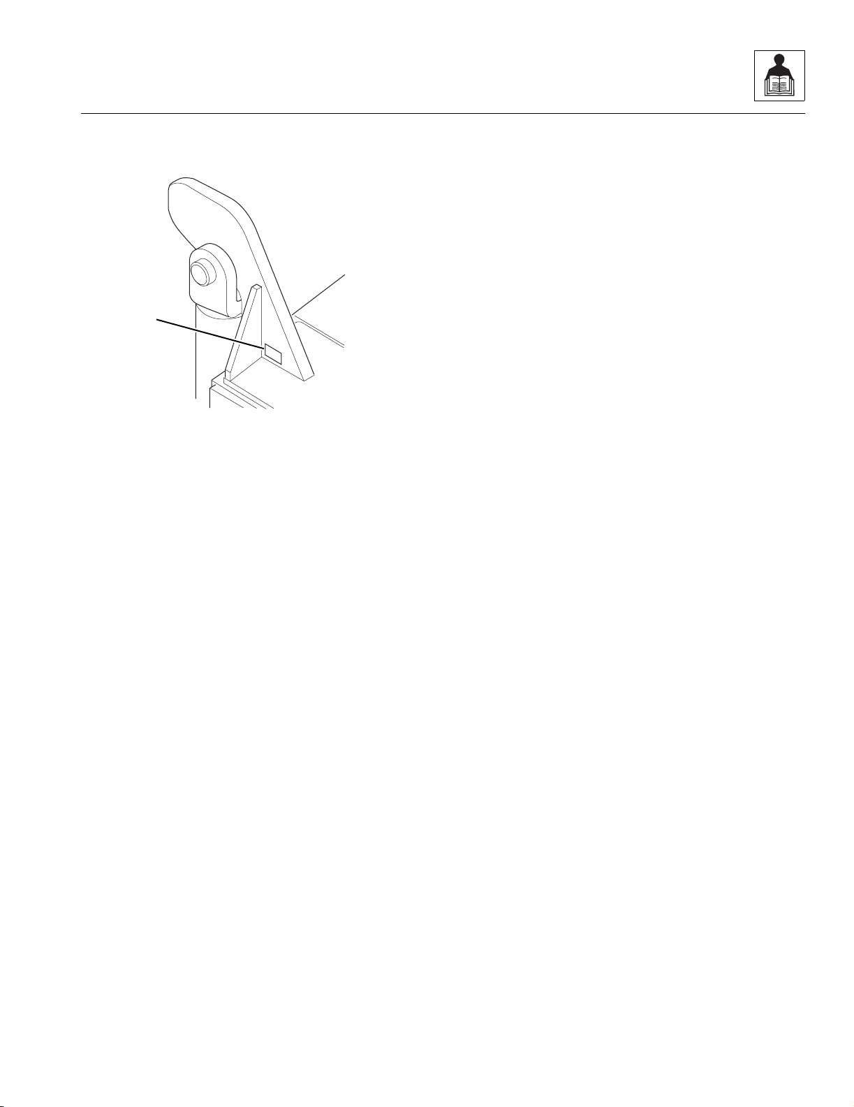
An owners/operators manual is supplied with each
vehicle and must be kept in the owners/operators manual
holder (Fig. 1-1, 1) located on the cab post to the left and
below the operator’s seat.
Figure 1-1 The Owners/Operators Manual Holder
In the event that the owners/operators manual is missing,
consult the local OmniQuip Authorized Service Center
(ASC) or the OmniQuip Service Department before
proceeding.
MH0770
1

1.3
Model 6042 Legacy Origin 7/02
Safety Practices
1.3 TRAINING MECHANICS AS
OPERATORS
Because it is necessary to move the vehicle to service or
maintain the vehicle, it is necessary that all mechanics
are OSHA trained and certified as operators. A mechanic
trained in the proper operation of the vehicle can better
determine whether all functions are operating correctly.
At the time of original purchase, the purchaser of this
vehicle was instructed by the seller on its proper use.
When this vehicle is to be serviced or maintained by
someone other than the purchaser, make certain that the
mechanic is trained, in accordance with the OSHA
regulations listed in the NOTICE below, and reads and
understands the SKY TRAK Model 6042 Legacy
Telescopic Material Handler Owners/Operators Manual
before
operating or maintaining the vehicle.
NOTICE: Under OSHA rules, it is the responsibility of the
employer to provide operator training. Successful
completion and certification of Safety Training for Rough
Terrain Forklifts is required. Operator Training Kits are
available by calling the Ken Cook Company at
(414) 466-6060. An order form for these kits is available
through our website, http://www.omniquip.com.
In addition, make sure that the mechanic has completed
a walk-around inspection of the vehicle, is familiar with all
decals and/or decal plates on the vehicle, and has
demonstrated the correct use of all controls.
1.4 SAFETY INFORMATION
The following information provides general safety
instructions, including examples of hazard statements
with signal words, notification of hazards, methods to
help avoid hazards and the consequences of failing to
follow the safety information. To avoid possible death or
injury, carefully read and follow all safety messages. Fully
understand the potential causes of death or injury.
In the event of an accident, know where to obtain medical
assistance and how to use a first-aid kit and fire
extinguisher/fire suppression system. Keep emergency
telephone numbers (fire department, ambulance, rescue
squad/paramedics, police department, etc.) nearby. If
working alone, check with another person routinely to
help ensure personal safety.
The information in this manual does not replace any other
safety rules or proper judgment. Governmental
authorities and employers also have their own sets of
rules, codes, regulations and laws. Before starting work
at a site, check with the supervisor or safety coordinator
and ask about the safety policy. Learn the safety
requirements in effect before operating, maintaining,
servicing or testing the vehicle. Safety depends on
following safety requirements.
1.4.1 Safety Alert Symbol
The exclamation mark within a triangle is the Safety Alert
Symbol.
This symbol means “Attention! Become Alert! Your
Safety Is Involved!” The symbol is used to attract
attention to safety hazards found on the vehicle safety
decals and throughout this manual.
OP0330
Safety Practices
1.4
Model 6042 Legacy Origin 7/02
1.4.2 Hazard Statements
Signal words and messages are used in conjunction with
the safety alert symbol to create hazard statements.
These hazard statements convey important information
about safety.
Four types of hazard statements are used in this manual.
Each statement indicates the existence and degree of
relative risk of the hazard described within the statement
that follows the signal word.
Explanations of the types of hazard statements are as
follows:
The signal word “DANGER” indicates an imminently
hazardous situation which, if not avoided, will result in
death or serious injury.
The signal word “WARNING” indicates a potentially
hazardous situation which, if not avoided, could result in
death or serious injury.
The signal word “CAUTION” indicates a potentially
hazardous situation which, if not avoided, could result in
minor or moderate injury.
The signal word “CAUTION,” used without the safety
alert symbol, indicates a potentially hazardous situation
which, if not avoided, could result in property damage.
For safe maintenance of the vehicle, read, understand
and follow all DANGER, WARNING and CAUTION
information.
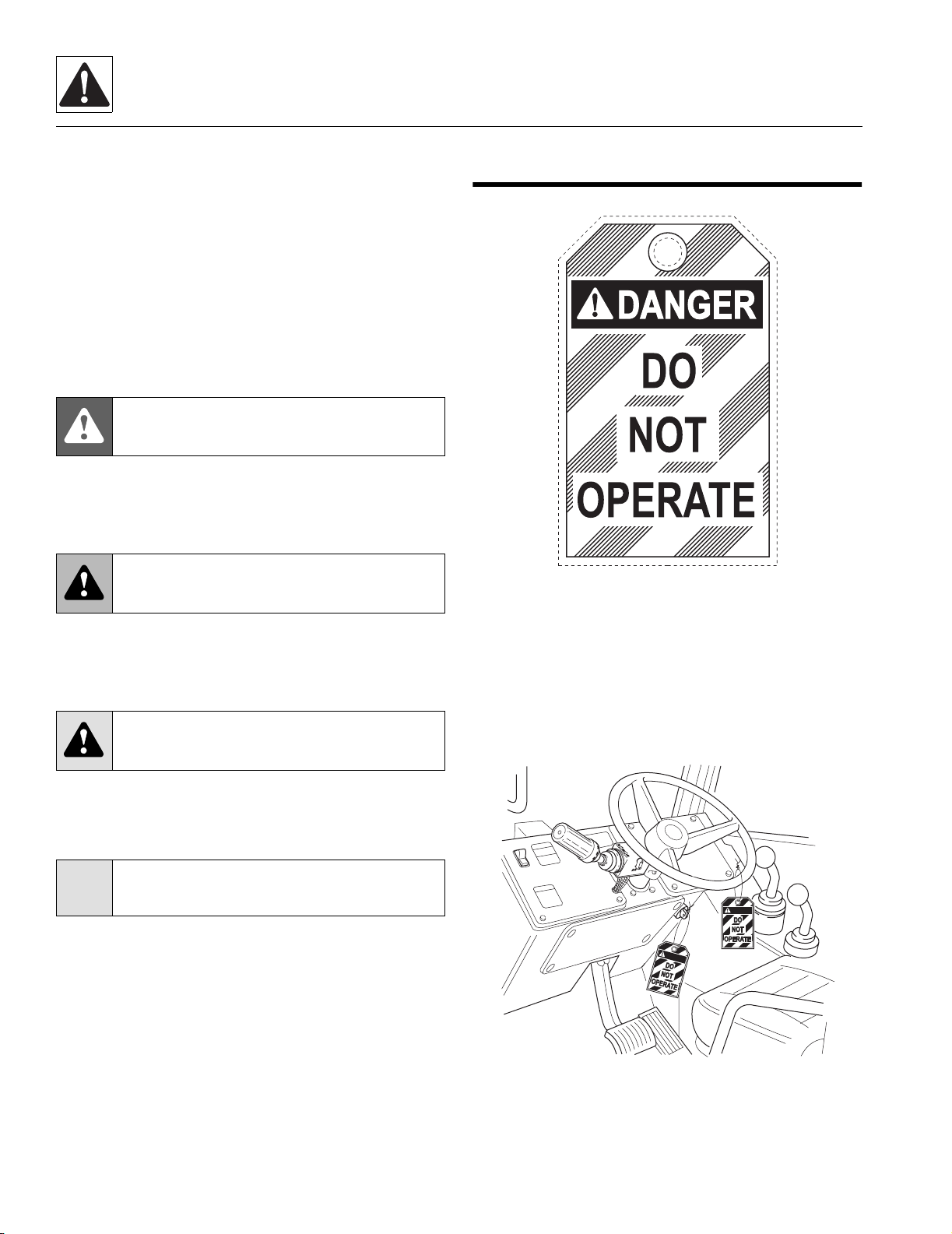
1.5 ACCIDENT PREVENTION TAG
USAGE
Figure 1-2 Accident Prevention Tag
Before beginning any maintenance or service, place an
Accident Prevention Tag (Fig. 1-2) on both the ignition
key switch and the steering wheel (Fig. 1- 3), stating that
the vehicle should not be operated. Actual Accident
Prevention Tags, which can be punched out and used,
are included as the last page in this manual. Retain these
Accident Prevention Tags for reuse at a later date.
Figure 1-3 Place Accident Prevention Tags on Both the
Ignition Key Switch and the Steering Wheel
DANGER:
WARNING:
CAUTION:
CAUTION:
MC0690
DANGER
DANGER
OH1720

1.5
Model 6042 Legacy Origin 7/02
Safety Practices
1.6 SAFETY INSTRUCTIONS
Following are general safety statements to consider
before
performing maintenance procedures on a vehicle.
Additional statements related to specific tasks and
procedures are located throughout this manual and are
listed prior to any work instructions to provide safety
information before the hazard occurs.
For all safety messages, carefully read, understand and
follow the instructions before
proceeding.
1.6.1 Personal Hazards
HAIR and CLOTHING: DO NOT wear loose clothing or
jewelry. Tie up or restrain hair. Wear the correct safety
equipment for the job (including but not limited to: hard
hat; safety shoes; safety glasses, goggles, or face shield;
heavy gloves; hearing protection; reflective clothing; wet-
weather gear; respirator or filter mask).
EYE PROTECTION: Always wear appropriate eye
protection when chiseling, grinding, sanding, welding,
painting, repairing hydraulic systems, or checking, testing
or charging the battery.
BREATHING PROTECTION: Wear respiratory
protection when grinding or painting.
HEARING PROTECTION: Always wear hearing
protection in a high-noise area.
FOOT PROTECTION: Wear protective footwear with
reinforced toe caps and slip-resistant soles.
LIFTING: NEVER lift a heavy object without the help of at
least one assistant or a suitable sling and hoist.
1.6.2 Equipment Hazards
OWNERS/OPERATORS MANUAL: Before operating the
vehicle, carefully read, understand and follow the owners/
operators manual.
OPERATIONAL PROTECTION: Before operating the
vehicle or returning it for operational use, check that the
Operator’s Protective Structure is intact, undamaged,
unmodified and secure.
LIFTING OF EQUIPMENT: Before using any lifting
equipment (chains, slings, brackets, hooks, etc.), verify
that it is of the proper capacity, in good working condition
and properly attached.
NEVER stand or otherwise become positioned under a
suspended load or under raised equipment. The load or
equipment could fall or tip.
DO NOT use a hoist or jack to support raised equipment.
A hoist or jack failure can allow the equipment to fall or tip.
Always support equipment with proper capacity blocks or
stands that are properly rated for the load.
COMPRESSED AIR: Before and during the use of
compressed air, wear eye protection and advise other
personnel in the work area that compressed air is about
to be used.
HAND TOOLS: Always use the proper tool for the job;
keep tools clean and in good working order, and use
special service tools only as recommended.

Safety Practices
1.6
Model 6042 Legacy Origin 7/02
1.6.3 General Hazards
SOLVENTS: Only use approved solvents, and solvents
that are known to be safe for use.
HOUSEKEEPING: Keep the work area and operator’s
cab clean and remove all hazards (debris, oil, tools, etc.).
FIRST AID: Immediately clean, dress and report all
injuries (cuts, abrasions, burns, etc.), no matter how
minor. Know the location of a first-aid kit, and know how
to use it.
CLEANLINESS: Wear eye protection, and clean all
components with a high-pressure or steam cleaner
before attempting service.
When removing hydraulic components, plug hose ends
and connections to prevent excess leakage and
contamination. Place a suitable catch basin beneath the
vehicle to capture fluid run-off.
1.6.4 Operational Hazards
OPERATIONAL CONSIDERATIONS: Before operating
the vehicle, carefully read, understand and follow the
owners/operators manual.
ENGINE: Stop the engine before performing any service.
DANGEROUS START: Place Accident Prevention Tags
on both the ignition key switch and the steering wheel
before attempting to perform any service or maintenance.
Disconnect battery leads. Place a warning sign on a
vehicle that is dangerous to start, if leaving the vehicle
unattended.
VENTILATION: Avoid prolonged engine operation in
enclosed areas without adequate ventilation.
RADIATOR CAP: Always wear steam-resistant, heat-
protective gloves when opening the radiator cap. Cover
cap with a clean, thick cloth and turn slowly to the first
stop to relieve pressure.
SOFT SURFACES AND SLOPES: NEVER work on a
vehicle that is parked on a soft surface or slope (inclined
ground or hill). The vehicle must be on a hard, level
surface with the wheels blocked when performing any
service. Obtain assistance, block all wheels, and add
supports if necessary before beginning any work.
SUPPORTS AND STRAPS: Install safe, stable supports,
slings or straps beneath or around a component or
structural member before beginning any work.
FLUID PRESSURE: Before loosening any hydraulic or
diesel fuel component, hose or tube, turn engine OFF.
Wear heavy, protective gloves and eye protection.
NEVER check for leaks using any part of your body; use
a piece of cardboard or wood instead. If injured, seek
medical attention immediately. Diesel fuel leaking under
pressure can explode. Hydraulic fluid and diesel fuel
leaking under pressure can penetrate the skin, causing
infection, gangrene and other serious personal injury.
Relieve all pressure before disconnecting any
component, part, line or hose. Slowly loosen parts and
allow release of residual pressure before removing any
part or component. Before starting engine or applying
pressure, use components, parts, hoses and pipes that
are in good condition, connected properly and tightened
to the proper torque. Capture fluid in an appropriate
container and dispose of it in accordance with prevailing
environmental regulations.
PRESSURE TESTING: When conducting any test, only
use test equipment that is correctly calibrated and in good
condition. Use the correct equipment in the proper
manner, and make changes or repairs as indicated by the
test procedures to achieve the desired results.
LEAVING VEHICLE: Lower the attachment to the ground
before leaving the vehicle.
TIRE PRESSURE: Always keep tires inflated to the
proper pressure to help prevent dangerous travel and
load-handling situations. DO NOT over-inflate tires.
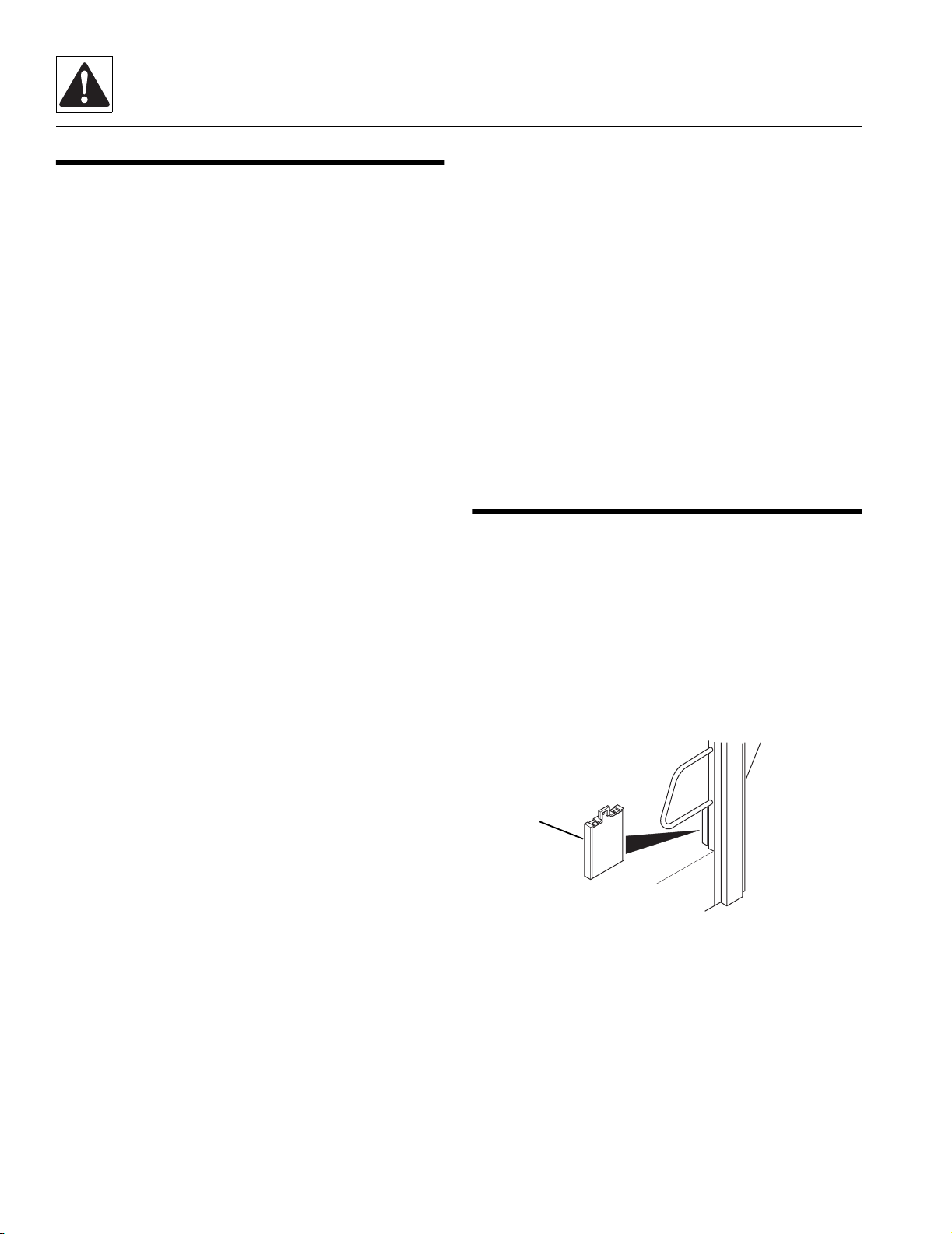
1.7 EMERGENCY EXIT REAR WINDOW
The rear window in the enclosed cab can be used as an
emergency exit by removing the latch pins (Fig. 1-4, 1)
located on the two window latches (2). Once the latch
pins have been removed, the window (3) can be swung
open.
Figure 1-4 Emergency Exit Rear Window Latch Pins
4
1
0
9
7
9
1
2.
3.
1.
OH1730
1
3
2
~
1.7
Model 6042 Legacy Origin 7/02
Safety Practices
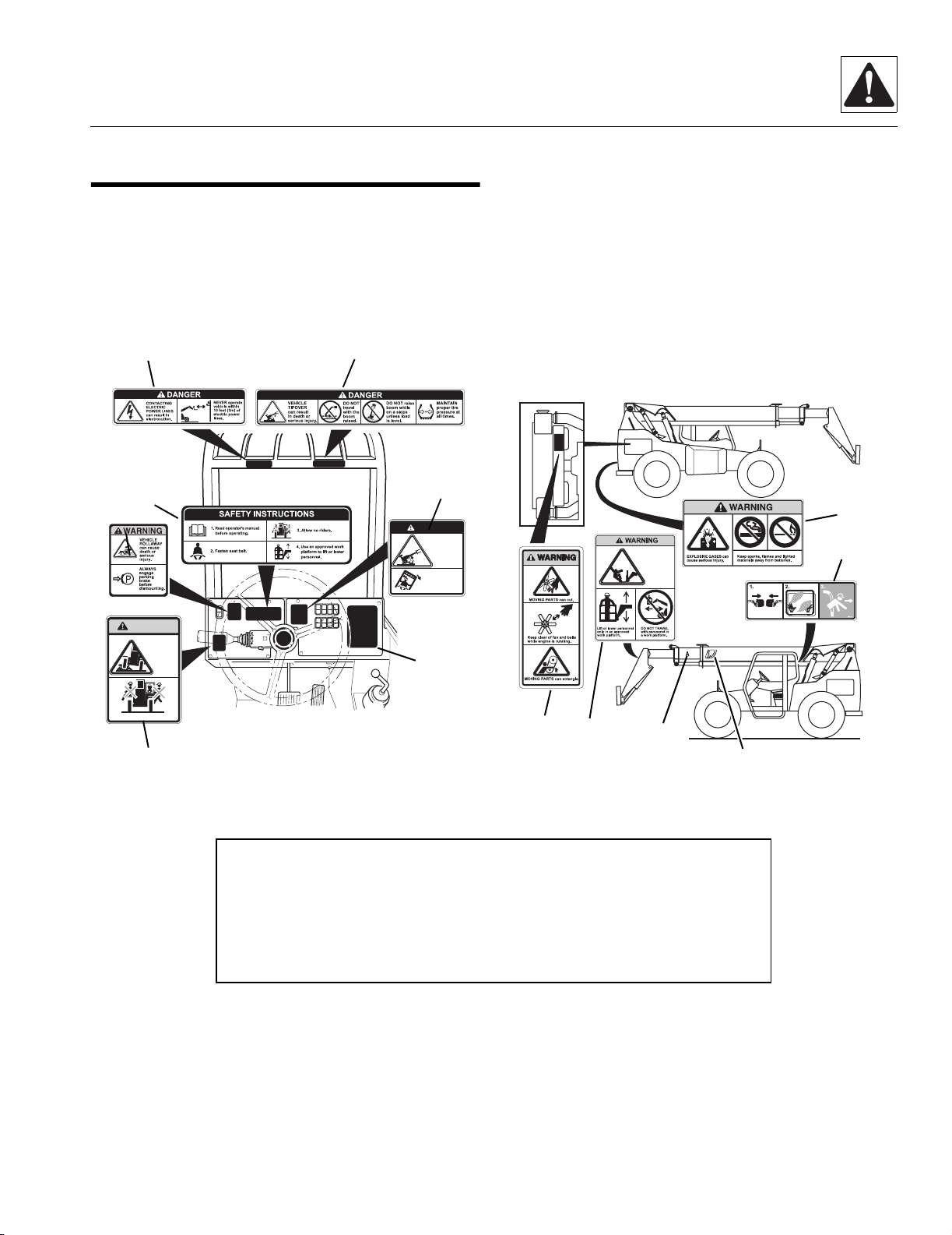
1.8 HAZARD/EMERGENCY
INFORMATION DECALS
Locations of vehicle hazard and other emergency
information decals are shown below. As part of routine
maintenance, check that ALL hazard and emergency
information decals on the vehicle are present and
readable. Keep all decals clean.
If a replacement decal is needed, refer to the owners/
operators manual and parts catalog for the latest parts
numbers and ordering information, or, contact OmniQuip
Textron Parts Worldwide directly at:
Domestic: 1-888-872-5123
or
International: 1-262-268-8958
Note: Many of these hazard related decals are available free of charge by
calling OmniQuip Textron Parts Worldwide at 1-888-872-5123 (Domestic) or
1-262-268-8958 (International).
WARNING
Allow no riders
AVOID
CRUSHING,
falling off
vehicle can
cause death
or serious
injury
DO NOT JUMP.
Brace yourself.
Stay in cab.
Keep seat belt on.
if vehicle tips.
Jumping can
result in death
or serious
injury.
DANGER
AVOID CRUSHING
FALLING OFF ATTACHMENT,
can result in death or
serious injury.
OH17422
OA14402
5
3
6
7
4
1
2
10
11
12
13
9
8
1. No Riders WARNING
2. Vehicle Rollaway WARNING
3. Safety Instructions
4. Electrocution DANGER
5. Tipover DANGER - Operating
6. Do Not Jump DANGER
7. Load Chart Booklet
8. Moving Parts WARNING
9. Carrying Personnel WARNING
10. Boom Extend Letters
11. Boom Angle Indicator
12. Explosive Gases WARNING
13. Emergency Exit (Enclosed Cab Only)

Safety Practices
1.8
Model 6042 Legacy Origin 7/02
This Page Intentionally Left Blank

2.1
Model 6042 Legacy Origin 7/02
Section 2
General Information and Specifications
Contents
PARAGRAPH TITLE PAGE
2.1 6042 Component Terminology . . . . . . . . . . . . . . . . . . . . . . . . . . . . . . . . . . . . . . . . . . 2.3
2.2 Introduction . . . . . . . . . . . . . . . . . . . . . . . . . . . . . . . . . . . . . . . . . . . . . . . . . . . . . . . . .2.4
2.2.1 Service Methods. . . . . . . . . . . . . . . . . . . . . . . . . . . . . . . . . . . . . . . . . . . . . . . . 2.4
2.2.2 The Owners/Operators Manual . . . . . . . . . . . . . . . . . . . . . . . . . . . . . . . . . . . . 2.4
2.2.3 Replacement Parts and Warranty Information . . . . . . . . . . . . . . . . . . . . . . . . . 2.4
2.2.4 Disclaimer. . . . . . . . . . . . . . . . . . . . . . . . . . . . . . . . . . . . . . . . . . . . . . . . . . . . . 2.5
2.3 Torques. . . . . . . . . . . . . . . . . . . . . . . . . . . . . . . . . . . . . . . . . . . . . . . . . . . . . . . . . . . . . 2.6
2.3.1 Fasteners . . . . . . . . . . . . . . . . . . . . . . . . . . . . . . . . . . . . . . . . . . . . . . . . . . . . . 2.6
2.3.2 Bolts and Nuts . . . . . . . . . . . . . . . . . . . . . . . . . . . . . . . . . . . . . . . . . . . . . . . . . 2.6
2.3.3 SAE 37° Flare Hydraulic Fittings . . . . . . . . . . . . . . . . . . . . . . . . . . . . . . . . . . . 2.6
2.3.4 SAE Flat Face O-Ring Seal Hydraulic Fittings . . . . . . . . . . . . . . . . . . . . . . . . . 2.9
2.4 Metric Conversion Factors . . . . . . . . . . . . . . . . . . . . . . . . . . . . . . . . . . . . . . . . . . . . . 2.12
2.4.1 Approximate American to Metric Conversions . . . . . . . . . . . . . . . . . . . . . . . . . 2.12
2.4.2 Approximate Metric to American Conversions . . . . . . . . . . . . . . . . . . . . . . . . . 2.13
2.5 Specifications . . . . . . . . . . . . . . . . . . . . . . . . . . . . . . . . . . . . . . . . . . . . . . . . . . . . . . . 2.14
2.5.1 Vehicle Dimensions (With Standard 12-ply 13.00-24 Tires) . . . . . . . . . . . . . . . 2.14
2.5.2 Vehicle Weights . . . . . . . . . . . . . . . . . . . . . . . . . . . . . . . . . . . . . . . . . . . . . . . . 2.16
2.5.3 Attachment Weights . . . . . . . . . . . . . . . . . . . . . . . . . . . . . . . . . . . . . . . . . . . . . 2.17
2.5.4 Performance Specifications . . . . . . . . . . . . . . . . . . . . . . . . . . . . . . . . . . . . . . . 2.17
2.5.5 Hydraulic Cylinder Performance Specifications . . . . . . . . . . . . . . . . . . . . . . . . 2.18
2.5.6 Electrical System . . . . . . . . . . . . . . . . . . . . . . . . . . . . . . . . . . . . . . . . . . . . . . . 2.19
2.5.7 Engine Performance Specifications . . . . . . . . . . . . . . . . . . . . . . . . . . . . . . . . . 2.20
2.5.8 Fluid and Lubricant Capacities . . . . . . . . . . . . . . . . . . . . . . . . . . . . . . . . . . . . . 2.21
2.5.9 Hydraulic System . . . . . . . . . . . . . . . . . . . . . . . . . . . . . . . . . . . . . . . . . . . . . . . 2.22
2.5.10 Tires . . . . . . . . . . . . . . . . . . . . . . . . . . . . . . . . . . . . . . . . . . . . . . . . . . . . . . . . . 2.22
2.5.11 Miscellaneous Specifications . . . . . . . . . . . . . . . . . . . . . . . . . . . . . . . . . . . . . . 2.22
2.5.12 Tamper Proofing . . . . . . . . . . . . . . . . . . . . . . . . . . . . . . . . . . . . . . . . . . . . . . . . 2.23
2.5.13 Fork Ratings . . . . . . . . . . . . . . . . . . . . . . . . . . . . . . . . . . . . . . . . . . . . . . . . . . . 2.23

General Information and Specifications
2.2
Model 6042 Legacy Origin 7/02
2.6 Fluids, Lubricants and Capacities . . . . . . . . . . . . . . . . . . . . . . . . . . . . . . . . . . . . . . . 2.23
2.6.1 Axles (Differential Housings) . . . . . . . . . . . . . . . . . . . . . . . . . . . . . . . . . . . . . . 2.23
2.6.2 Axle Wheel Ends . . . . . . . . . . . . . . . . . . . . . . . . . . . . . . . . . . . . . . . . . . . . . . . 2.24
2.6.3 Transmission. . . . . . . . . . . . . . . . . . . . . . . . . . . . . . . . . . . . . . . . . . . . . . . . . . . 2.24
2.6.4 Lubrication Points (Grease Fittings) . . . . . . . . . . . . . . . . . . . . . . . . . . . . . . . . . 2.24
2.6.5 Hydraulic System . . . . . . . . . . . . . . . . . . . . . . . . . . . . . . . . . . . . . . . . . . . . . . . 2.25
2.6.6 Engine. . . . . . . . . . . . . . . . . . . . . . . . . . . . . . . . . . . . . . . . . . . . . . . . . . . . . . . . 2.25
2.6.7 Drive Shaft Splines . . . . . . . . . . . . . . . . . . . . . . . . . . . . . . . . . . . . . . . . . . . . . . 2.26
2.6.8 General Anti-Corrosion . . . . . . . . . . . . . . . . . . . . . . . . . . . . . . . . . . . . . . . . . . . 2.26
2.6.9 Electrical . . . . . . . . . . . . . . . . . . . . . . . . . . . . . . . . . . . . . . . . . . . . . . . . . . . . . . 2.26
2.6.10 Paint . . . . . . . . . . . . . . . . . . . . . . . . . . . . . . . . . . . . . . . . . . . . . . . . . . . . . . . . . 2.27
2.6.11 Thread Locking Compound . . . . . . . . . . . . . . . . . . . . . . . . . . . . . . . . . . . . . . . 2.27
2.7 Cleaning . . . . . . . . . . . . . . . . . . . . . . . . . . . . . . . . . . . . . . . . . . . . . . . . . . . . . . . . . . . . 2.27
2.8 Replacement . . . . . . . . . . . . . . . . . . . . . . . . . . . . . . . . . . . . . . . . . . . . . . . . . . . . . . . . 2.28
2.9 Hoses and Tubes . . . . . . . . . . . . . . . . . . . . . . . . . . . . . . . . . . . . . . . . . . . . . . . . . . . . . 2.28
2.9.1 Hose and Tube Inspection . . . . . . . . . . . . . . . . . . . . . . . . . . . . . . . . . . . . . . . . 2.28
2.9.2 Hose and Tube Installation . . . . . . . . . . . . . . . . . . . . . . . . . . . . . . . . . . . . . . . . 2.28
2.10 Bearings . . . . . . . . . . . . . . . . . . . . . . . . . . . . . . . . . . . . . . . . . . . . . . . . . . . . . . . . . . . . 2.28
2.10.1 Bearing Removal . . . . . . . . . . . . . . . . . . . . . . . . . . . . . . . . . . . . . . . . . . . . . . . 2.28
2.10.2 Bearing Cleaning . . . . . . . . . . . . . . . . . . . . . . . . . . . . . . . . . . . . . . . . . . . . . . . 2.28
2.10.3 Bearing Installation . . . . . . . . . . . . . . . . . . . . . . . . . . . . . . . . . . . . . . . . . . . . . . 2.29
2.11 Pressure Testing and Adjustment . . . . . . . . . . . . . . . . . . . . . . . . . . . . . . . . . . . . . . . 2.29
2.12 After Service Startup and Checks . . . . . . . . . . . . . . . . . . . . . . . . . . . . . . . . . . . . . . . 2.29
2.12.1 After Service Startup . . . . . . . . . . . . . . . . . . . . . . . . . . . . . . . . . . . . . . . . . . . . 2.29
2.12.2 After Electrical/Electronic Component Service . . . . . . . . . . . . . . . . . . . . . . . . . 2.29
2.12.3 After Hydraulic Component Service . . . . . . . . . . . . . . . . . . . . . . . . . . . . . . . . . 2.30
2.12.4 After Brake System Service . . . . . . . . . . . . . . . . . . . . . . . . . . . . . . . . . . . . . . . 2.30
2.12.5 After Fuel System Service . . . . . . . . . . . . . . . . . . . . . . . . . . . . . . . . . . . . . . . . 2.30
2.12.6 After Transmission Service or Replacement. . . . . . . . . . . . . . . . . . . . . . . . . . . 2.30
2.12.7 After Tire and Wheel Service . . . . . . . . . . . . . . . . . . . . . . . . . . . . . . . . . . . . . . 2.31
2.12.8 After Engine Service. . . . . . . . . . . . . . . . . . . . . . . . . . . . . . . . . . . . . . . . . . . . . 2.31
2.12.9 After Boom Service. . . . . . . . . . . . . . . . . . . . . . . . . . . . . . . . . . . . . . . . . . . . . . 2.31
2.12.10 After Axle Service . . . . . . . . . . . . . . . . . . . . . . . . . . . . . . . . . . . . . . . . . . . . . . . 2.31
2.3
Model 6042 Legacy Origin 7/02
General Information and Specifications
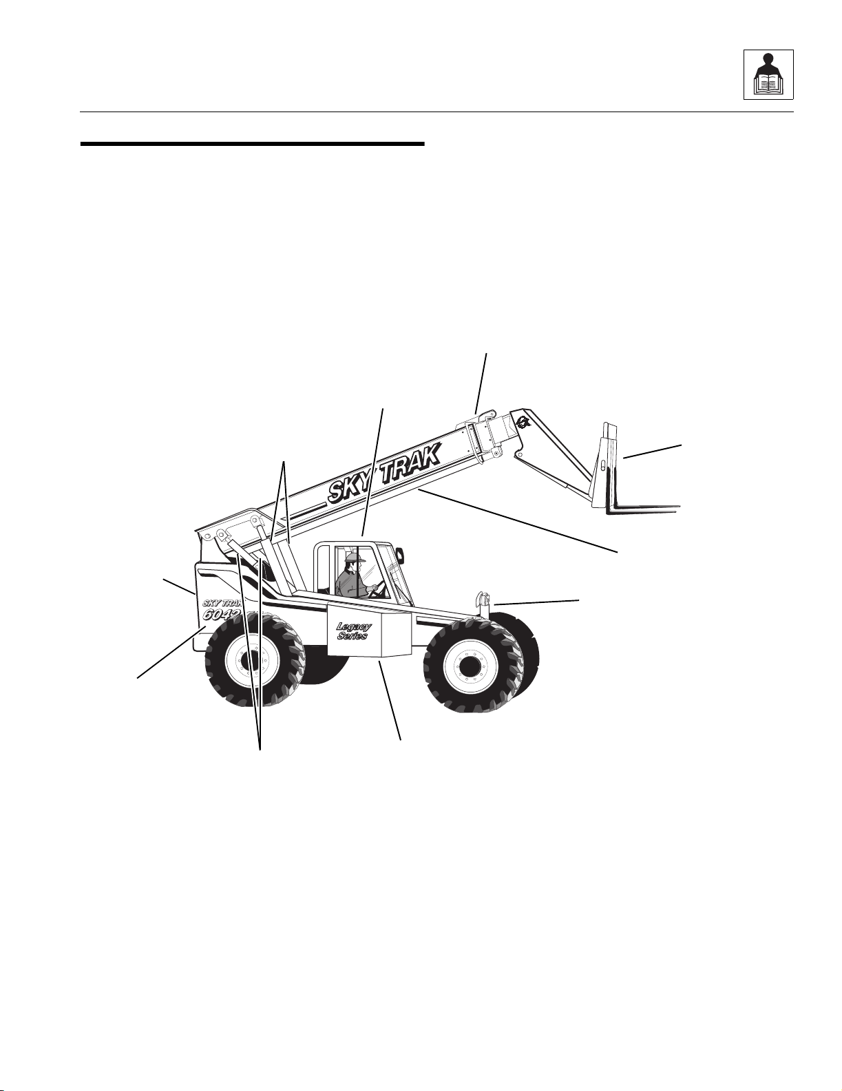
2.1 6042 COMPONENT TERMINOLOGY
To understand the safety, operation and maintenance
information presented in this manual, it is necessary that
the operator/mechanic be familiar with the names and
locations of the major assemblies on this vehicle. The
following illustration identifies the components that are
referred to throughout this manual.
MA10,0650
Operator’s
Protective
Structure
Boom
Assembly
Hydraulic
Oil Tank
Carriage
Assembly
Rear Door
(Not Visible)
Engine
Compartment
Frame Sway
Cylinder
Slave
Cylinders (2)
Lift/Lower
Cylinders (2)
Extend/Retract
Cylinder
~

General Information and Specifications
2.4
Model 6042 Legacy Origin 7/02
2.2 INTRODUCTION
2.2.1 Service Methods
Appropriate service methods and proper repair
procedures are essential for safe, reliable operation of
this vehicle and the safety of the individual doing the
work. This Service Manual provides general direction for
accomplishing service and repair work with tested, effective
techniques. Following them will assure reliability.
There are many variations in procedures, techniques,
tools and parts for servicing vehicles, as well as work
skills. This manual cannot possibly anticipate all such
variations and provide advice or cautions for each one.
Accordingly, anyone who intends to depart from the
instructions in this manual must first consider personal
safety and then vehicle integrity.
IMPORTANT: OmniQuip recommends the use of
environmentally sound waste storage and disposal
practices. NEVER drain fluids on the ground or into a
sewer or catch basin. Use suitable collection containers,
then store and/or dispose of waste products in an
approved and safe manner. Check and obey all Federal,
State and/or Local regulations regarding waste storage,
disposal and recycling.
2.2.2 The Owners/Operators Manual
The Owners/Operators Manual provides information you
need to properly operate and maintain this vehicle.
IMPORTANT: Before you operate this vehicle, read the
manual completely and carefully, so that you will understand
the safety instructions and the operation of the controls
and safety equipment. You must comply with all Danger,
Warning and Caution notices. They are for your benefit.
All references to the right side, left side, front and rear are
given from the operator’s seat looking in a forward direction.
2.2.3 Replacement Parts and Warranty
Information
For reference when ordering replacement parts or making
service inquiries about the vehicle, the vehicle serial
number is required to help assure the provision of correct
parts and information. Before ordering parts or initiating
service inquiries, make note of the serial number.
2.5
Model 6042 Legacy Origin 7/02
General Information and Specifications
The vehicle serial number plate (Fig. 2-1, 1) is located at
the front of the vehicle on the frame sway cylinder upright.
Figure 2-1 Vehicle Serial Number Plate Location
IMPORTANT: The replacement of any part on this
vehicle with any other than a OmniQuip authorized
replacement part can adversely affect the performance,
durability, or safety of the vehicle, and will void the
warranty. OmniQuip disclaims liability for any claims or
damages, whether regarding property damage, personal
injury or death arising out of the use of unauthorized
replacement parts.
A warranty registration form must be filled out by the
OmniQuip Authorized Service Center (ASC), signed by
the purchaser and returned to OmniQuip when the
vehicle is sold and/or put into use.
Registration activates the warranty period and helps to
assure that warranty claims are promptly processed. To
guarantee full warranty service, verify that the distributor
has returned the business reply card of the warranty
registration form to OmniQuip.
2.2.4 Disclaimer
OmniQuip reserves the right to make changes to and to
add improvements upon its product at any time, without
public notice or obligation. OmniQuip also reserves the
right to discontinue manufacturing any product at its
discretion at any time.
OH0280
1

General Information and Specifications
2.6
Model 6042 Legacy Origin 7/02
2.3 TORQUES
2.3.1 Fasteners
All fasteners (nuts, bolts, washers, etc.) are equal to SAE
Grade 5 (PC8.8) and are plated, unless otherwise specified.
2.3.2 Bolts and Nuts
Unless otherwise specified, the following values apply for
Grade 5 (PC8.8) nuts and bolts:
2.3.3 SAE 37° Flare Hydraulic Fittings
a. Assembly Procedure
Follow these steps when tightening hose ends, tube ends
and fitting swivel ends onto fitting male end connections
(Refer to Fig. 2-2).
Improper assembly of this type of joint will result in
leaking joints. Over tightening can result in cracking of the
female swivel seat or deformation of the male fitting
tapered seat. Under tightening will result in the joint
loosening during normal usage. Foreign material on
either seal surfaces will cause damage to one or both
mating parts when the joint is tightened, resulting in a
leaking joint.
1. Inspect both the male and female sealing cone
surfaces for burrs, scratches, dents, other damage,
or foreign material. If any damage is found on the
seat the part is to be rejected as unusable. Clean off
any foreign material from the sealing surfaces before
assembly.
2. Align the mating parts and check to see that the flare
seats properly on the nose of the fitting.
3. Finger tighten the nut onto the fitting. If necessary a
wrench may be used to snug the nut against the
fitting (30 lb-in maximum torque). This is considered
the “finger tight” (Fig. 2-2, 1) condition.
Figure 2-2 F.F.F.T. Tightening Method
Size Torque Size Torque
Inchlb-ftNmmmNmlb-ft
1/4 9 12 6,0 10 7
5/16 17 24 8,0 25 18
3/8 31 42 10,0 50 37
7/16 50 68 -- -- --
1/2 75 102 12,0 80 59
9/16 110 150 14,0 130 95
5/8 150 203 16,0 200 146
3/4 250 340 20,0 360 263
7/8 380 515 22,0 510 372
1.0 585 793 24.0 650 475
MA10,0810
1
2
3
4
~
~
~
2.7
Model 6042 Legacy Origin 7/02
General Information and Specifications
4. Using a permanent type ink marker, make a mark
(Fig. 2-2, 2) on one of the flats on the nut and
continue it onto the static fitting or port.
5. Complete the joint by wrench tightening (Fig. 2-2, 3)
the nut
the number of flats (4) specified in the table
for the size and type of fitting. This assembly
procedure is referred to as Flats From Finger
Tight (FFFT).
6. A less desirable tightening method is nut torque.
First follow 1 & 2 above. Apply clean petroleum
based oil to the male thread. Finger tighten the nut
onto the fitting. Torque the nut to the value listed in
the table.
b. Straight O-Ring Boss Fittings To
O-Ring Boss Ports
Improper assembly of this joint will result in leaking joints.
Under tightening of the fitting will result in the fitting
loosening during normal operation and the joint leaking.
Damaging the o-ring during assembly will result in
immediate joint leakage.
1. Inspect components to ensure that male and female
port threads and sealing surfaces are free of burrs,
nicks, or scratches, or any foreign material. If any
damage is found the bad part must not be used.
Clean any foreign material from the mating parts
before assembly.
2. Lubricate the o-ring with a clean petroleum based
lubricant.
3. Screw the fitting into the port.
4. Torque the fitting to the value listed in table.
Hose Ends, Tube Ends and Fitting Swivel Ends
To Fitting Male Ends
SAE
Size
Tube
Conn.
(FFFT)
Swivel Nut
or
Hose Conn.
(FFFT)
Torque lb-ft (Nm)
w/Oiled
Threads
4 2 2 16 ± 3 (22 ± 4)
5 2 2 19 ± 4 (26 ± 5)
6 1-1/2 1-1/4 25 ± 5 (34 ± 7)
8 1-1/2 1 49 ± 10 (66 ± 14)
10 1-1/4 1 74 ± 11 (100 ± 15)
12 1-1/4 1 103 ± 15 (140 ± 20)
14 1 1 121 ± 18 (164 ± 24)
16 1 1 135 ± 35 (183 ± 47)
20 1 1 166 ± 33 (225 ± 45)
24 1 1 210 ± 40 (285 ± 54)
32 1 1 314 ± 54 (426 ± 73)
O-Ring Boss Fittings To
O-Ring Boss Ports
SAE Size Torque lb-ft (Nm)
4 14 ± 1 (19 ± 1)
5 18 ± 1 (24 ± 1)
6 23 ± 1 (31 ± 1)
8 41 ± 1 (56 ± 1)
10 45 ± 3 (61 ± 4)
12 72 ± 3 (98 ± 4)
14 95 ± 4 (129 ± 5)
16 118 ± 5 (160 ± 7)
20 154 ± 7 (209 ± 10)
24 162 ± 8 (220 ± 11)
32 229 ± 11 (311 ± 15)

General Information and Specifications
2.8
Model 6042 Legacy Origin 7/02
c. Adjustable (Angle) O-Ring Boss Fittings To
O-Ring Boss Ports
Improper assembly of this joint will result in a leaking joint.
Failure to position the locknut properly will result in
damage to the o-ring. Under tightening of the fitting will
result in the fitting loosening during normal operation and
the joint leaking. Damaging the o-ring during assembly
will result in immediate joint leakage.
1. Inspect components to ensure that male and female
port threads and sealing surfaces are free of burrs,
nicks, or scratches, or any foreign material. If any
damage is found the bad part must not be used.
Clean any foreign material from the mating parts
before assembly.
Figure 2- 3 Adjustable Fitting to Port
2. Back off the locknut as far as possible (Fig. 2-3, 1).
Make sure the back-up washer is not loose. If the
back-up washer is loose the fitting must be replaced.
3. Lubricate the o-ring (Fig. 2-3, 2) and male thread
with a clean petroleum based lubricant.
4. Screw the fitting into the port as far as possible by
hand (Fig. 2-3, B & C).
5. To align the tube end (Fig. 2-3, 3) of the fitting to
accept the mating tube or hose, unscrew the fitting
as required but not more than one turn.
6. Using two wrenches, hold the fitting in the desired
position and tighten the locknut (Fig. 2-3, 4) to the
appropriate torque value listed in the table in Section
2.3.3, b. “Straight O-Ring Boss Fittings To
O-Ring Boss Ports.”
d. Pipe Fittings to Pipe Ports
Improper assembly of this joint will result in a leaking joint
and possible damage to the port.
1. Inspect the port and fitting to insure that there are no
burrs, nicks, or foreign material. If any thread
damage is found the part must not be used. Clean
off any foreign material.
2. Apply sealant/lubricant to male pipe thread. If Teflon
tape is used it should be wrapped 1.5 to 2 turns in a
clockwise direction when viewed from the pipe
thread end. With any sealant the first 1 to 2 threads
should be left uncovered to avoid system
contamination.
3. Screw the connector into the port finger tight.
4. Wrench tighten the fitting to the appropriate Turns
From Finger Tight (TFFT) from Table 4. Make sure
that angle fittings are aligned with the mating tube or
hose within the listed number of turns. Never back
off (loosen) pipe thread connectors to achieve
alignment.
C
D
B
A
MF0620
2
1
3
4
Pipe Fittings To Pipe Ports
Pipe Thread Size Turns From Finger Tight
(T.F.F.T
1/8" 2 - 3
1/4" 2 - 3
3/8" 2 - 3
1/2" 2 - 3
3/4" 2 - 3
1" 1-1/2 - 2-1/2
1-1/4" 1-1/2 - 2-1/2
1-1/2" 1-1/2 - 2-1/2
2" 1-1/2 - 2-1/2
2.9
Model 6042 Legacy Origin 7/02
General Information and Specifications
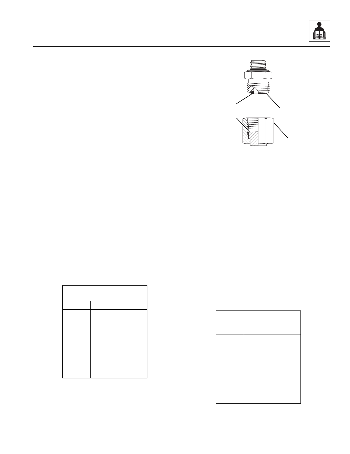
2.3.4 SAE Flat Face O-Ring Seal
Hydraulic Fittings
a. Assembly Procedure
Improper assembly of this type of joint will result in
leaking joints. Under tightening will result in the joint
loosening during normal usage. Foreign material on
either seal surfaces will cause damage to one or both
mating parts when the joint is tightened resulting in a
leaking joint. The absences of the fitting o-ring will cause
the joint to leak.
1. Inspect both the male (Fig. 2-4, 1) and female (2)
sealing surfaces for burrs, scratches, dents, other
damage, or foreign material. If any damage is found
on either surface, the part is to be rejected as
unusable. Clean off any foreign material from the
sealing surfaces before assembly.
2. Inspect the male fitting for the presence of the seal
o-ring (Fig. 2-4, 3). Inspect the o-ring for any sign of
damage. If the o-ring is missing or damaged replace
it.
3. Apply clean petroleum based oil to the male thread.
4. Place the flat surface of the female connector
(Fig. 2-4, 1) in full contact with the o-ring (3) in the
male connector.
5. Finger tighten the nut (Fig. 2-4, 4) onto the fitting.
6. Complete the joint by tightening the nut
to the torque
specified in the table. For hoses and swivel fittings
use a second wrench to keep the female connector
from moving during tightening.
Figure 2-4 Flat Face O-Ring Seal Connections
b. Straight O-Ring Boss Fittings To
O-Ring Boss Ports
Improper assembly of this joint will result in leaking joints.
Under tightening of the fitting will result in the fitting
loosening during normal operation and the joint leaking.
Damaging the o-ring during assembly will result in
immediate joint leakage.
1. Inspect components to ensure that male and female
port threads and sealing surfaces are free of burrs,
nicks, or scratches, or any foreign material. If any
damage is found the bad part must not be used.
Clean any foreign material from the mating parts
before assembly.
2. Lubricate the o-ring and male thread with a clean
petroleum based lubricant.
3. Screw the fitting into the port.
4. Torque the fitting to the values found in table.
O-Ring Boss Fittings To
O-Ring Boss Ports
SAE Size Torque lb-ft (Nm)
4 19 ± 5 (26 ± 7)
6 35 ± 5 (47 ± 7)
8 52 ± 7 (70 ± 10)
10 83 ± 17 (112 ± 23)
12 120 ± 20 (163 ± 27)
16 165± 35 (224 ± 47)
20 215 ± 65 (292 ± 88)
24 252 ± 77 (342 ± 104)
O-Ring Boss Fittings To
O-Ring Boss Ports
SAE Size Torque lb-ft (Nm)
4 15 ± 1 (20 ± 1)
6 25 ± 1 (34 ± 1)
8 55 ± 5 (75 ± 7)
10 76 ± 5 (103 ± 7)
12 130 ± 5 (176 ± 7)
16 210± 10 (285 ± 14)
20 245 ± 35 (332 ± 47)
24 315 ± 45 (427 ± 61)
MA10,0800
1
2
3
4

General Information and Specifications
2.10
Model 6042 Legacy Origin 7/02
c. Adjustable (Angle) O-Ring Boss Fittings To
O-Ring Boss Ports
Improper assembly of this joint will result in a leaking joint.
Failure to position the locknut properly will result in
damage to the o-ring. Under tightening of the fitting will
result in the fitting loosening during normal operation and
the joint leaking. Damaging the o-ring during assembly
will result in immediate joint leakage.
1. Inspect components to ensure that male and female
port threads and sealing surfaces are free of burrs,
nicks, or scratches, or any foreign material. If any
damage is found the bad part must not be used.
Clean any foreign material from the mating parts
before assembly.
Figure 2- 5 Adjustable Fitting to Port
2. Back off the locknut as far as possible (Fig. 2-5, 1).
Make sure the back-up washer is not loose. If the
back-up washer is loose the fitting must be rejected.
3. Lubricate the o-ring (Fig. 2-5, 2) and male thread
with clean petroleum based lubricant.
4. Screw the fitting into the port as far as possible by
hand (Fig. 2-5, B & C).
5. To align the tube end (Fig. 2-5, 3) of the fitting to
accept the mating tube or hose, unscrew the fitting
as required but not more than one turn.
6. Using two wrenches, hold the fitting in the desired
position and tighten the locknut (Fig. 2-5, 4) to the
appropriate torque value listed in the table in Section
2.3.4, b. “Straight O-Ring Boss Fittings To
O-Ring Boss Ports.”
d. Pipe Fittings to Pipe Ports
Improper assembly of this joint will result in a leaking joint
and possible damage to the port.
1. Inspect the port and fitting to insure that there are no
burrs, nicks, or foreign material. If any thread
damage is found the part must not be used. Clean
off any foreign material.
2. Apply sealant/lubricant to male pipe thread. If Teflon
tape is used it should be wrapped 1.5 to 2 turns in a
clockwise direction when viewed from the pipe
thread end. With any sealant the first 1 to 2 threads
should be left uncovered to avoid system
contamination.
3. Screw the connector into the port finger tight.
4. Wrench tighten the fitting to the appropriate Turns
From Finger Tight (TFFT) from Table 4. Make sure
that angle fittings are aligned with the mating tube or
hose within the listed number of turns. Never back
off (loosen) pipe thread connectors to achieve
alignment.
A
B
C
D
MA10,0820
2
1
3
4
Pipe Fittings To Pipe Ports
Pipe Thread Size Turns From Finger Tight
(T.F.F.T
1/8" 2 - 3
1/4" 2 - 3
3/8" 2 - 3
1/2" 2 - 3
3/4" 2 - 3
1" 1-1/2 - 2-1/2
1-1/4" 1-1/2 - 2-1/2
1-1/2" 1-1/2 - 2-1/2
2" 1-1/2 - 2-1/2

2.11
Model 6042 Legacy Origin 7/02
General Information and Specifications
This Page Intentionally Left Blank

General Information and Specifications
2.12
Model 6042 Legacy Origin 7/02
2.4 METRIC CONVERSION FACTORS
2.4.1 Approximate American to
Metric Conversions
When this is known Multiply by To find
TORQUE
(moment of force)
Pound/feet (lb-ft) 1.356 Newton meters (Nm)
Pound/inches (lb-in) 0.113 Newton meters (Nm)
POWER
Horsepower (hp) 745.7 Watts
SPEED (velocity)
Miles per hour (mph) 1.609 Kilometers per hour
(km/hr; kph)
LENGTH (distance)
Inches (in) 25.4 Millimeters (mm)
Inches (in) 2.5 Centimeters (cm)
Feet (ft) 30.5 Centimeters (cm)
Feet (ft) 0.305 Meters (m)
Yards (yd) 0.9 Meters (m)
Miles (mi) 1.6 Kilometers (km)
AREA
Square inches (in
2
) 6.5 Square centimeters (cm
2
)
Square feet (ft
2
) 0.09 Square meters (m
2
)
Square yards (yd
2
) 0.8 Square meters (m
2
)
Square miles (mi
2
) 2.6 Square kilometers (km
2
)
Acres 0.4 Hectares (ha)
MASS (weight)
Ounces (oz) 28.3 Grams (g)
Pounds (lb) 0.4536 Kilograms (kg)
Short tons (2000 lb) 0.9 Metric ton (t)
When this is known Multiply by To find
VOLUME
Teaspoons (tsp) 5 Milliliters (ml)
Tablespoons (Tbsp) 15 Milliliters (ml)
Cubic inches (in
3
) 16 Milliliters (ml)
Fluid ounces (fl oz) 30 Milliliters (ml)
Cups (c) 0.24 Liters
Pints (pt) 0.47 Liters
Quarts (qt) 0.95 Liters
Gallons (gal) 3.8 Liters
Cubic feet (ft
3
) 0.03 Cubic meters (m
3
)
Cubic yards (yd
3
) 0.76 Cubic meters (m
3
)
AIR PRESSURE
Pounds per
square inch (psi) 6.895 Kilopascals (kPa)
HYDRAULIC PRESSURE
Pounds per
square inch (psi) 0.069 Bar
TEMPERATURE (exact)
To determine degrees Celsius (° C), subtract 32, then
multiply by 0.56; (° F -32) x 0.56 = ° C.

2.13
Model 6042 Legacy Origin 7/02
General Information and Specifications
2.4.2 Approximate Metric to
American Conversions
When this is known Multiply by To find
TORQUE
(moment of force)
Newton meters (Nm) 0,738 Pounds/feet (lb-ft)
Newton meters (Nm) 8,85 Pounds/inches (lb-in)
POWER
Watts 0,0013 Horsepower (hp)
SPEED (velocity)
Kilometers per
hour (km/hr; kph) 0,621 Miles per hour (mph)
LENGTH (distance)
Millimeters (mm) 0,0394 Inches (in)
Centimeters (cm) 0,394 Inches (in)
Meters (m) 3,281 Feet (ft)
Meters (m) 1,1 Yards (yd)
Kilometers (km) 0,621 Miles (mi)
When this is known Multiply by To find
AREA
Square centimeters
(cm
2
) 0,4 Square inches (in
2
)
Square meters (m
2
) 1,1 Square yards (yd
2
)
Square kilometers
(km
2
) 0,6 Square miles (mi
2
)
Hectares (10000 m
2
)2,5 Acres
MASS (weight)
Grams (g) 0,035 Ounces (oz)
Kilograms (kg) 2,2 Pounds (lb)
Metric ton
(1000 kg) (t) 1,1 Short tons
VOLUME
Milliliters (ml) 0,03 Fluid ounces (fl oz)
Milliliters (ml) 0,06 Cubic inches (in
3
)
Liters 2,1 Pints (pt)
Liters 1,06 Quarts (qt)
Liters 0,26 Gallons (gal)
Cubic meters (m
3
) 35 Cubic feet (ft
3
)
Cubic meters (m
3
) 1,3 Cubic yards (yd
3
)
AIR PRESSURE
Kilopascals (kPa) 0,145 Pounds per square
inch (psi)
HYDRAULIC PRESSURE
Bar 14,5 Pounds per square
inch (psi)
TEMPERATURE (exact)
To determine degrees Fahrenheit (° F), multiply degrees
Celsius (° C) by 1.8, then add 32; (° C x 1.8) + 32 = ° F.

General Information and Specifications
2.14
Model 6042 Legacy Origin 7/02
2.5 SPECIFICATIONS
2.5.1 Vehicle Dimensions (With Standard 12-ply 13.00-24 Tires)
Description (Fig. 2- 6)
(A) Length (without Attachment) 220" (5588 mm)
(B) Width 98" (2489 mm)
(C) Height (Boom Lowered) 102" (2591 mm)
(D) Wheelbase 113" (2870 mm)
(E) Tread 84" (2134 mm)
(F) Ground Clearance 16" (406 mm)
(G) Turning Radius, Curb to Curb 165" (4191 mm)
(H) Turning Radius, Clearance 168" (4267 mm)
(I) Maximum Lift Height, Boom Extended 41' 11" (12,8 m)
(J) Maximum Lift Height, Boom Retracted 21' 7" (6,6 m)
(K) Maximum Below Grade Depth, Boom Extended 3' 1" (940 mm)
(L) Maximum Reach, from Front of Front Tires 27' 11" (8,5 m)
(M) Maximum Reach at Maximum Lift Angle,
Boom Extended
6' 4" (1930 mm)
(N) Maximum Reach at Maximum Lift Angle,
Boom Retracted
-20" (-508 mm)
(O) Maximum Reach at Minimum Lift Angle,
Boom Extended
21' 9" (6,6 m)
(P) Maximum Boom Lift Angle 68.4°
(Q) Minimum Boom Lift Angle -8°
(R) Angle of Departure 27°
Fork Tilt Angle:
(S) At Minimum Boom Angle - UP 11°
(T) At Minimum Boom Angle - DOWN -101°
(U) At Maximum Boom Angle - UP 87°
(V) At Maximum Boom Angle - DOWN -25°
Frame Tilt Angle (Not Shown):
Right 10.0°
Left 10.0°

2.15
Model 6042 Legacy Origin 7/02
General Information and Specifications
Figure 2-6 Vehicle Dimensions with Standard Tires
S
U
N
J
M
I
0.0
O
L
K
V
F
R
C
Q
D
A
T
24.0"
P
G
H
BE
MA10,0670

General Information and Specifications
2.16
Model 6042 Legacy Origin 7/02
2.5.2 Vehicle Weights
Curb Weight w/48" Carriage (Open Cab) 23,520 lb (10.668 kg)
Curb Weight w/48" Carriage (Enclosed Cab) 23,720 lb (10.759 kg)
Operating Load 6,000 lb (2721 kg)
Working Weight (Machine working weight is figured with 72" carriage, two 48" pallet forks, 25%-full fuel tank, and
standard bias ply tires [no hydrofill]):
Open Cab:
Front Axle 9,030 lb (4.096 kg)
Rear Axle 14,710 lb (6.672 kg)
Total (Open Cab) 23,740 lb (10.768 kg)
Closed Cab:
Front Axle 9,130 lb (4.141 kg)
Rear Axle 14,810 lb (6.718 kg)
Total (Closed Cab) 23,940 lb (10.859 kg)
 Loading...