


SKF TKSA 31 & TKSA 41
Instructions for use

Table of contents
EC Declaration of conformity........................................ |
2 |
||
Safety recommendations.............................................. |
3 |
||
1. |
Introduction.......................................................... |
4 |
|
|
1.1 |
Shaft alignment overview ......................................... |
4 |
|
1.2 |
Principle of operation................................................. |
5 |
|
1.3 |
Case content................................................................ |
6 |
|
1.4 |
Product description ................................................... |
7 |
2. |
Getting started...................................................... |
8 |
|
|
2.1 |
Mounting the V-brackets........................................... |
8 |
|
2.2 |
Switching on the display unit.................................... |
9 |
|
2.3 |
Connecting the wireless MU on TKSA 41............. |
10 |
|
2.4 |
Connecting the wired MU on TKSA 31/41........... |
11 |
|
2.5 |
Adjusting the lasers................................................. |
12 |
|
2.6 |
Home screen............................................................ |
13 |
|
2.7 |
Charging.................................................................... |
14 |
|
2.8 |
Charging the measuring units ............................... |
14 |
3. |
Take a measurement........................................... |
15 |
|
|
3.1 |
3 Ways to start an alignment................................. |
15 |
|
3.2 |
Dimensions screen.................................................. |
16 |
|
3.3 |
9-12-3 Measurements .......................................... |
17 |
|
3.4 |
Automatic measurements...................................... |
19 |
|
3.5 |
Free measurement (TKSA 41 only) ...................... |
20 |
|
3.6 |
Backlash.................................................................... |
21 |
4. |
Correct the alignment ......................................... |
22 |
|
|
4.1 |
Results page............................................................. |
22 |
|
4.2 |
Vertical correction – Side view – Shimming ........ |
23 |
|
4.3 |
Horizontal correction – Top view ........................... |
25 |
|
4.4 |
Recheck – remeasure.............................................. |
27 |
5. |
Create a report.................................................... |
28 |
|
|
5.1 |
Reporting.................................................................. |
28 |
|
5.2 |
Report creation page............................................... |
29 |
|
5.3 |
Report content and browser .................................. |
30 |
6. QR codes, machine library, soft foot..................... |
32 |
||
|
6.1 |
QR code (TKSA 41 only) ......................................... |
32 |
|
6.2 |
Machine library ........................................................ |
33 |
|
6.3 |
Soft foot 1................................................................. |
35 |
|
6.4 |
Soft foot 2................................................................. |
36 |
7. |
Settings.............................................................. |
37 |
|
|
7.1 |
Main settings menu................................................. |
37 |
|
7.2 |
User settings ............................................................ |
38 |
|
7.3 |
Measurements settings .......................................... |
39 |
|
7.4 |
Display unit and measuring unit info.................... |
40 |
|
7.5 |
Languages ................................................................ |
41 |
|
7.6 |
Units and date & clock ............................................ |
42 |
|
7.7 |
General settings....................................................... |
43 |
8. |
Troubleshooting.................................................. |
44 |
|
|
8.1 |
Perform a reset........................................................ |
44 |
|
8.2 |
Power modes ........................................................... |
44 |
|
8.3 |
Charging.................................................................... |
44 |
|
8.4 |
Firmware update ..................................................... |
45 |
|
8.5 |
Wireless connection troubleshooting.................... |
46 |
9. |
Technical speciications ....................................... |
47 |
|
Original instructions
SKF TKSA 31 & TKSA 41 |
1 |
EU Declaration of conformity
We, SKF Maintenance Products, Kelvinbaan 16, 3439 MT Nieuwegein, The Netherlands herewith declare that the following products:
SKF Shaft Alignment Tool TKSA 31 & TKSA 41
TKSA 31 has been designed and manufactured in accordance with: EMC DIRECTIVE 2014/30/EU as outlined in the harmonized norm for EN 61326-1:2013 Electrical equipment for measurement, control and laboratory use – Part 1: General Requirements, EN 55011: 2009 +A1:2010, EN 61000-4-2: 2009, EN 61000-4-3: 2006 +A1:2008 +A2:2010, EN 61000-4-4: 2004 +A1:2010, EN 61000-4-5: 2006, EN 61000-4-6: 2009, EN 61000-4-11: 2004
TKSA 41 has been designed and manufactured in accordance with: RADIO EQUIPMENT DIRECTIVE 2014/53/EU as outlined in the harmonized norm EN 61010:2010, EN 61326-1:2013,
EN 55011: 2009 +A1:2010, EN 61000-4-2: 2009, EN 61000-4-3: 2006 +A1:2008 +A2:2010,
EN 61000-4-4: 2004 +A1:2010, EN 61000-4-5: 2006, EN 61000-4-6: 2009, EN 61000-4-11: 2004, EN 301 489-1 v2.1.1, EN 301 489-17 v3.1.1, EN 300 328 v2.1.1
EUROPEAN ROHS DIRECTIVE 2011/65/EU
The laser is classiied in accordance with the EN 60825-1:2007. The laser complies with 21 CFR 1040.10 and 1040.11 except for deviations pursuant to Laser Notice No. 50, dated June 24, 2007.
TKSA 41 only: The enclosed device complies with Part 15 of the FCC Rules.
47CFR: 2011 Part 15 Sub Part B Unintentional Radiators. Contains FCC ID: 0C3BM1871, QDID: B020997. Manufacturer’s Name, Trade Name or Brand Name: NovaComm. Model Name: NVC-MDCS71.
Nieuwegein, The Netherlands, August 2017
Sébastien David – Manager Product Development and Quality
2 |
SKF TKSA 31 & TKSA 41 |

WARNING
LASER RADIATION
DO NOT STARE INTO BEAM
CLASS 2 LASER PRODUCT
P≤1mW L=635nm
Safety recommendations
•The complete instructions for use are available on this device and the latest version on SKF.com.
•Read and follow all warnings and operating instructions in this document before handling and operating the equipment. You can be seriously injured; equipment and data can be damaged if you do not follow the safety warnings.
•TKSA 31/41 uses Class 2 lasers with output power < 1.0mW. Never stare directly into the laser beam. Never direct the laser into anyone else’s eyes.
•Dress properly. Do not wear loose clothing or jewellery. Keep your hair, clothing, and gloves away from moving parts.
•Do not overreach. Keep proper footing and balance at all times to enable better control of the device during unexpected situations.
•Use safety equipment. Non-skid safety shoes, hard hat or hearing protection must be used for appropriate conditions.
•Never work on energized equipment unless authorized by a responsible authority. Always turn off the power of the machine before you start.
•Do not expose the equipment to rough handling or impacts this will void the warranty.
•Avoid direct contact with water, wet surfaces, or condensing humidity.
•Do not attempt to open the device, this will void the warranty.
•Use only accessories that are recommended by SKF.
• Device service must be performed only by qualiied SKF repair personnel.
• We recommend calibrating the tool every 2 years.
SKF TKSA 31 & TKSA 41 |
3 |

1. Introduction
1.1 Shaft alignment overview
Shaft misalignment is one of the most signiicant and most preventable contributors to premature machine failure.
When a machine is placed in service with less than optimal shaft alignment, the following conditions are likely:
•Poor machine performance
•Increased power consumption
•Increased noise and vibration
•Premature bearing wear
•Accelerated deterioration of gaskets, packing, and mechanical seals
•Higher coupling wear rates
•Increased unplanned downtime
Proper alignment is achieved when the centrelines of each shaft are co-linear when the machine is under load and at normal operating temperatures. This is often referred to as shaft-to-shaft alignment.
If the shafts of a machine train are not co-linear, when the machine is in operation, they are misaligned.
In essence, the objective is to have a straight line through the centres of all of the shafts of the machines. The SKF Shaft Alignment Tool TKSA 31/41 is a laser shaft alignment tool that allows an easy and accurate method for aligning the shafts of a driving machine (eg electric motor) and a driven machine (eg. pump).
4 |
SKF TKSA 31 & TKSA 41 |

1.2 Principle of operation
The TKSA 31/41 uses two measuring units (MU) both provided with a laser diode and a CCD detector. As the shafts are rotated through 180° any parallel or angular misalignment causes the two laser lines to del ect from their initial relative position.
The measurements from the two detectors are used to automatically calculate the misalignment and guide the user through the vertical (shimming) and horizontal correction steps.
The measurements can be taken according to the 9-12-3 method or with a free measurement method on the TKSA 41. Measurements can also be taken automatically without action from the user on the Display Unit.
The TKSA 41 can be used with the display l at on the l oor or vertical.
The screen orientation will adapt to the display unit orientation.
Results can be saved on a PDF report and exported on a USB stick.
SKF TKSA 31 & TKSA 41 |
5 |

1.3 Case content
|
|
|
9 |
8 |
|
|
5 |
|
1 |
|
6 |
|
|
|
|
|
|
7 |
|
2 |
4 |
4 |
3 |
|
|
1. |
1 |
× TKSA 31/41 Display unit |
8. |
1 |
× 12V DC 3A Power supply |
2. |
1 |
× TKSA 31/41 S Measuring unit |
9. |
Country adapters (US, UK, EU, AUS) |
|
3. |
1 |
× TKSA 31/41 M Measuring unit |
10. |
2 |
× Micro USB to USB cables* |
4. |
2 |
× Shaft V-Brackets with chains |
11. |
Printed Quick Start Guide (EN)* |
|
5. |
90 mm Extension rods (TKSA 41 only) |
12. |
Printed certii cate of Calibration and conformance* |
||
6. |
1 |
× Chain tightening rod |
13. |
1 |
× Page of QR code stickers (TKSA 41 only)* |
7. |
5 m (16 ft) metric and imperial measuring tape |
* |
not shown |
||
6 |
SKF TKSA 31 & TKSA 41 |
1.4 Product description
• Large 29 mm CCD detector
• Electronic inclinometers
• Bluetooth 4.0 LE (TKSA 41)
• Red Line laser
•2 × threaded
150 mm rods per V-bracket
• Multiple positions for chain nut |
• |
Large Resistive colour touchscreen |
|
• |
Rugged Design |
• Screen orientation fl ip function (TKSA 41)
SKF TKSA 31 & TKSA 41 |
7 |

2. Getting started
2.1 Mounting the V-brackets
Use the V-brackets to attach the measuring units (MU) to the shafts.
Make sure the unit marked “M” is attached to the Moveable machine and the unit marked “S” to the Stationary machine.
If it is not possible to attach the V-brackets directly to the shafts (e.g. in case of space problems) the ixtures can be attached to the coupling.
For shafts with diameter < 40 mm (< 1.5”) hook the chain to the anchor in the V-bracket from the inside.
The tightening knob should use the space closer to the rod.
For larger diameters hook the chain from the outside.
Remove the slack of the chain and tighten it irmly with the tensioning knobs with the rod tensioning bar.
Make sure the rods are irmly tightened to the brackets before mounting the measuring units.
Make sure the measuring units are irmly tightened on the rods and DO NOT lie on bracket.
Brackets are symmetric, they can be mounted either way.
8 |
SKF TKSA 31 & TKSA 41 |
2.2 Switching on the display unit
Press the red On/Off button on the display unit (DU) for > 1 sec.
The unit is fully started when it reaches the home screen.
Short press the red On/Off button on the display unit to:
• Start the DU.
• Put the DU in stand-by.
• Wake-up the DU from stand-by.
Note:
To restart/reset the unit, keep the On/Off button pressed until the display unit switches off (~6 seconds).
• The DU will enter deep sleep after 2 hours of inactivity.
• The DU will never turn off during an alignment job.
• The Display Unit does NOT need to be switched off.
Short press for stand-by only.
SKF TKSA 31 & TKSA 41 |
9 |

2.3 Connecting the wireless MU on TKSA 41
The Measuring Units can be connected in bluetooth (wireless) or via the USB cables for charging or in the event of a power loss.
See next chapter for USB connection.
•Turn On both MU with a short press on the red On/Off button.
•The front LED irst indicates the battery status:
• |
Green |
= Full |
• Amber |
= Low |
|
• |
Red |
= Charge now |
• The LED will start blinking in a blue colour to indicate the MU is |
|
|
trying to connect to the DU. |
|
|
The Bluetooth symbol appears in the top right corner of the display |
S |
M |
next to the “S” and “M” letters. |
|
|
• The MU will connect automatically to the DU. |
|
|
When connected, the battery level of the MU is shown. |
|
|
Note:
•Click on the top right corner (red zone on the right) of the display to open the MU settings.
•Once connected, the MU LED remains off.
•If the MUs do not connect, check the Troubleshooting section.
•Switch off the MU with a long press on the On/Off button until a steady red LED appears.
10 |
SKF TKSA 31 & TKSA 41 |
2.4 Connecting the wired MU on TKSA 31/41
The MU can be connected to the DU via USB cable.
•Make sure the MU are both switched off. (TKSA 41 only).
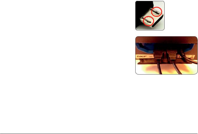
•Connect the USB cables to the Display Unit.
The USB Symbol on the cable should be facing upwards.
•Connect the Micro USB cables to the Measuring Units. The locking pins on the connector should be directed towards the front (laser part) of the MU.
•The MU will automatically connect to the DU.
A USB symbol will be shown next to the “S” and “M” letters.
Note:
• Switch Off the MU before disconnecting the USB cables. |
|
|
|
• |
See section Troubleshooting for any connection issue. |
S |
M |
• |
The micro USB ports on the MU are sealed from the inside and |
||
protected from dust and dirt ingress.
SKF TKSA 31 & TKSA 41 |
11 |

2.5 Adjusting the lasers
•Lock the “M” measuring unit (MU) in position.
•Adjust the height of the “S” unit so that its laser line hits the “M” MU in the centre of the detector, on the red mark.
•Lock irmly the “S” unit in position.
•Use the knob on top of the “M” unit to vertically adjust the laser position on the “S” unit.
12 |
SKF TKSA 31 & TKSA 41 |

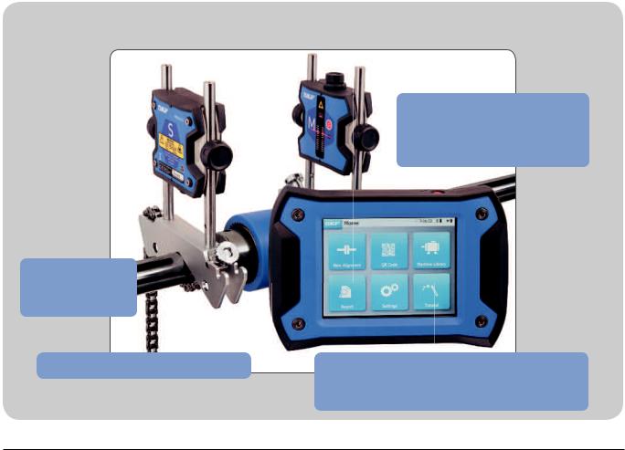
2.6 Home screen
SKF Menu
Start a new alignment job
Open Reports
Scan a QR code to recognize an existing machine or create a new machine
Open the machine library,
check previous alignments and start new ones
Open Settings |
Open Help |
SKF TKSA 31 & TKSA 41 |
13 |

2.7 Charging
•Connect the 12V power adapter to the charging port in the back of the DU.
•A battery charging indicator appears on the top right of the screen to indicate charging of the DU and MU.
Note:
•The display unit will charge in standby mode.
•The display unit will wake up when connected to power.
2.8 Charging the measuring units
•Connect the MU to the display unit with the micro USB cables.
•The charging symbol will be shown on the screen.
14 |
SKF TKSA 31 & TKSA 41 |
3. Take a measurement
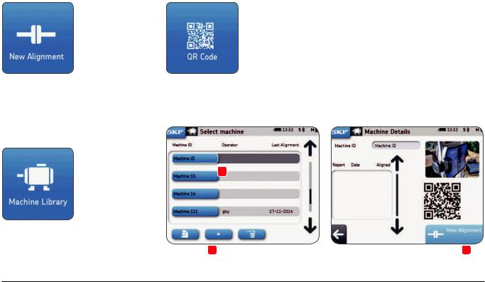
3.1 3 Ways to start an alignment
From the Home screen:
Click on “New alignment” Click on “QR code”
Click on “Machine library”
1
2 |
3 |
SKF TKSA 31 & TKSA 41 |
15 |
 Loading...