


 Loading...
SKF Flowline monitor FL15, FL50 & FL100
(Operating and maintenance instructions compliant with EU Directive 2014/30/EU)
FLMONITOR_10K_EN 8.1.2018

TABLE OF CONTENTS |
|
1 EU Declaration of Conformity ........................................................................................................................ |
4 |
2 Legal disclosure .............................................................................................................................................. |
5 |
Manufacturer ..................................................................................................................................................... |
5 |
Training courses................................................................................................................................................ |
5 |
Copyright ........................................................................................................................................................... |
5 |
Warranty............................................................................................................................................................ |
5 |
Disclaimer.......................................................................................................................................................... |
5 |
3 Explanation of symbols, signs and abbreviations...................................................................................... |
6 |
4 Safety instructions .......................................................................................................................................... |
9 |
General instructions........................................................................................................................................ |
9 |
General behaviour when handling the product............................................................................................... |
9 |
Intended use ................................................................................................................................................... |
9 |
Forseeable misuse ....................................................................................................................................... |
10 |
Painting of plastic parts prohibited................................................................................................................ |
10 |
Unauthorized modifications to the product ................................................................................................... |
10 |
Prohibition of certain activities ...................................................................................................................... |
10 |
Compliance with other applicable documents .............................................................................................. |
10 |
Notes concerning the type identification plate.............................................................................................. |
11 |
Notes concerning CE marking.................................................................................................................... |
11 |
Persons authorised to operate the device .................................................................................................. |
11 |
4.11.1 Operators ............................................................................................................................................. |
11 |
4.11.2 Mechanical specialist ........................................................................................................................... |
11 |
4.11.3 Electrician............................................................................................................................................. |
11 |
4.11.4 Providing briefing for external technicians ........................................................................................... |
12 |
4.11.5 Provision of personal protective equipment......................................................................................... |
12 |
Operation .................................................................................................................................................... |
12 |
4.12.1 Emergency stopping of the pump station ............................................................................................ |
12 |
4.12.2 Transport, installation, maintenance, malfunctions, repair, shutdown, disposal ................................ |
12 |
Commissioning and daily start-up .............................................................................................................. |
13 |
Cleaning...................................................................................................................................................... |
13 |
Residual risk ............................................................................................................................................... |
14 |
5 Delivery, returns and storage ....................................................................................................................... |
15 |
Delivery......................................................................................................................................................... |
15 |
Returns ......................................................................................................................................................... |
15 |
Storage ......................................................................................................................................................... |
15 |
6 Lubricants ...................................................................................................................................................... |
16 |
General information ...................................................................................................................................... |
16 |
Lubrication selection ..................................................................................................................................... |
16 |
Material compatibility .................................................................................................................................... |
17 |
Ageing of lubricants ...................................................................................................................................... |
17 |
7 General description ....................................................................................................................................... |
18 |
8 Design ............................................................................................................................................................. |
18 |
SKF Flowline monitor FL15 .......................................................................................................................... |
18 |
SKF Flowline monitor FL50 .......................................................................................................................... |
19 |
SKF Flowline monitor FL100 ........................................................................................................................ |
19 |
9 Operation ........................................................................................................................................................ |
20 |
FLMONITOR_10K_EN 8.1.2018 |
|
General ......................................................................................................................................................... |
20 |
LEDs in flow meters...................................................................................................................................... |
21 |
User’s interface in the control unit ................................................................................................................ |
22 |
Selecting a flow meter .................................................................................................................................. |
24 |
Selecting display mode................................................................................................................................. |
24 |
Flow rate adjustment .................................................................................................................................... |
24 |
9.6.1 FL15 and FL50 flow meter adjustment .................................................................................................. |
24 |
9.6.2 FL100 flow meter adjustment................................................................................................................. |
25 |
Start-up sequence ........................................................................................................................................ |
25 |
10 Settings......................................................................................................................................................... |
26 |
General ....................................................................................................................................................... |
26 |
Entering the setting mode........................................................................................................................... |
26 |
Exiting the setting mode ............................................................................................................................. |
27 |
10.3.1 Saving parameters and exiting ............................................................................................................ |
27 |
10.3.2 Exiting without saving parameters ....................................................................................................... |
27 |
Flow meter-specific settings ....................................................................................................................... |
27 |
10.4.1 Nominal flow rate ................................................................................................................................. |
27 |
10.4.2 Alarm limits........................................................................................................................................... |
28 |
10.4.3 Alarm filtering ....................................................................................................................................... |
28 |
10.4.4 Optional flow meterspecific settings .................................................................................................. |
29 |
10.4.5 Flow meter shutdown and start-up....................................................................................................... |
29 |
Monitor-specific settings ............................................................................................................................. |
30 |
10.5.1 Display units for flow rate and temperature ......................................................................................... |
30 |
10.5.2 Oil viscosity grade ................................................................................................................................ |
30 |
10.5.3 Flow meter type.................................................................................................................................... |
30 |
10.5.4 Pre-alarm limit ...................................................................................................................................... |
31 |
10.5.5 Alarm mode of Relay-CAN module...................................................................................................... |
31 |
10.5.6 CAN-bus ID-number............................................................................................................................. |
31 |
11 Installation .................................................................................................................................................... |
32 |
Mechanical installation................................................................................................................................ |
32 |
11.1.1 Monitor dimensions .............................................................................................................................. |
32 |
11.1.2 Pipe connections.................................................................................................................................. |
33 |
Electrical connections ................................................................................................................................. |
35 |
12 Maintenance ................................................................................................................................................. |
38 |
12.1.1 Removing and reinstalling sensor........................................................................................................ |
38 |
12.1.2 Removing and reinstalling flowmeter cover ......................................................................................... |
40 |
12.1.3 Removing and reinstalling flow tube assembly.................................................................................... |
41 |
12.1.4 Removing and reinstalling flow valve................................................................................................... |
42 |
12.1.5 Removing and reinstalling motherboard .............................................................................................. |
43 |
12.1.6 Installing optional Relay-CAN, mA-output or CAN module.................................................................. |
43 |
13 Technical specifications ............................................................................................................................. |
44 |
14 Optional modules ........................................................................................................................................ |
46 |
Relay-CAN module overall ......................................................................................................................... |
46 |
14.1.1 Relay general description .................................................................................................................... |
46 |
14.1.2 Operation of alarm relays..................................................................................................................... |
47 |
Individual alarms (SHL, SL) ........................................................................................................................... |
47 |
Individual alarms (DHL, DL and HL) .............................................................................................................. |
48 |
Individual alarms (DHL and DL) ..................................................................................................................... |
48 |
FLMONITOR_10K_EN 8.1.2018 |
|

Individual alarms (HL) .................................................................................................................................... |
49 |
Common alarms (C)....................................................................................................................................... |
50 |
Fault message................................................................................................................................................ |
50 |
CAN module ............................................................................................................................................... |
52 |
14.2.1 CAN bus connectors ............................................................................................................................ |
53 |
mA-output module ...................................................................................................................................... |
53 |
14.3.1 Features ............................................................................................................................................... |
54 |
14.3.2 Scaling of the analog outputs............................................................................................................... |
54 |
14.3.3 Connections ......................................................................................................................................... |
55 |
15 Troubleshooting .......................................................................................................................................... |
57 |
16 Cleaning........................................................................................................................................................ |
58 |
Cleaning agents.......................................................................................................................................... |
58 |
Exterior cleaning ......................................................................................................................................... |
58 |
.Interior cleaning ......................................................................................................................................... |
58 |
17 Spare parts ................................................................................................................................................... |
59 |
FLMONITOR_10K_EN 8.1.2018

1 EU Declaration of Conformity
(Declaration of conformity according to EMC Directive 2014/30/EU)
Oy SKF Ab
Teollisuustie 6 (P.O. Box 80)
FIN-40951 MUURAME
FINLAND
herewith declares that the product
SKF Flowline monitor
FL15, FL50 and FL100
conforms to the relevant requirements of directives
EMC |
2014/30/EU |
RoHS II |
2011/65/EU, (EU) 2015/863 |
The following harmonized standards have been applied:
•EN 61000-6-4:2007+A1:2011, for emissions
•EN 61000-6-2:2005, for immunity
•EN 50581:2013
Muurame |
April 11, 2017 |
Place |
Date |
Juha Kärkkäinen
Manager R&D Nordic
SKF Lubrication Business unit
FLMONITOR_10K_EN 8.1.2018
4

2 Legal disclosure
Manufacturer
Oy SKF Ab Finland Teollisuustie 6 FI-40951 MUURAME FINLAND
Tel: +358 20 7400 800 Fax: +358 20 7400 899 E-mail: skf-lube@skf.com www.skf.com/lubrication
Training courses
In order to provide a maximum of safety and economic viability, SKF carries out detailed training courses. It is recommended that the training courses are attended. For further information, please contact the provided SKF Service address.
Copyright
© SKF. All rights reserved.
Warranty
The instructions do not contain any information concerning warranties. Warranties and guarantees are described in our general terms and conditions. Notes related to the operating instructions The present operating instructions are original operating instructions of the manufacturer pursuant to Machinery Directive 2006/42/EC. The instructions are part of the described products and must be kept in an accessible location for further use.
Disclaimer
The manufacturer shall not be held responsible for damages caused by:
•accidents, or negligent or inappropriate use, assembly, operation, configuration, maintenance or repairs
•improper or late response to malfunctions
•unauthorised modifications to the product
•intent or negligence
•the use of non-original (non-SKF) spare parts
Liability for loss or damage resulting from the use of our products is limited to the maximum purchase price. Liability for consequential damages of any kind is excluded.
FLMONITOR_10K_EN 8.1.2018
5
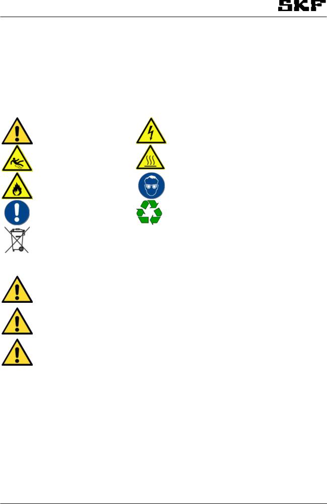
3 Explanation of symbols, signs and abbreviations
The following symbols are used in the safety instructions included in this manual to highlight conditions which are potentially harmful to people, materials or the environment.
Please follow the instructions provided especially in the highlighted conditions. Also, be sure that all operators read this manual and all safety instructions.
|
|
General warning |
|
|
Risk of electric shock |
|
|
|
|
|
|
|
|
|
|
Risk of falling |
|
|
Hot surface |
|
|
|
|
|
|
|
|
|
|
Fire hazard |
|
|
Wear personal protective |
|
|
|
|
|
equipment (goggles) |
|
|
|
|
|
|
|
|
|
|
|
|
|
|
|
|
|
|
General notes |
|
|
Disposal, recycling |
|
|
|
|
|
|
|
|
|
|
Dispose of cartridges in an |
|
|
|
|
|
environmentally friendly way |
|
|
|
|
|
|
|
|
|
|
|
|
|
|
|
|
|
|
|
|
|
Warning level |
|
Consequence |
Probability |
|
|
|
|
|
|
|
|
|
|
DANGER |
|
Death, serious |
imminent |
|
|
|
|
injury |
|||
|
|
|
|
|
||
|
|
|
|
|
|
|
|
|
WARNING |
|
Death, serious |
possible |
|
|
|
|
injury |
|||
|
|
|
|
|
||
|
|
|
|
|
|
|
|
|
CAUTION |
|
Minor injury |
possible |
|
|
|
|
|
|
|
|
|
|
NOTICE |
|
Property damage |
possible |
|
|
|
|
|
|
|
|
FLMONITOR_10K_EN 8.1.2018
6

|
Symbol |
|
|
|
|
|
Meaning |
|
|
|
|
|
|
|
|
|
|
|
|
|
|
|
|
|
|
|
|
|
|
|
|
|
Chronological guidelines |
|
|
|
|
|
|
|
|
|
|
|
|
|
|
|
|
|
|
|
|
|
|
|
|
|
List items |
|
|
|
|
|
|
|
|
|
|
|
|
|
|
||||
|
|
|
|
|
|
|
Indicates conditions which must be met before the activities |
|
||||
|
|
|
|
|
|
described in the title clause can be completed |
|
|||||
|
|
|
|
|
|
|
|
|||||
|
|
|
|
|
|
|
|
|
||||
|
|
|
|
|
|
|
Also indicates other factors, causes or consequences |
|
||||
|
|
|
|
|
|
|
|
|
|
|
|
|
|
re. |
regarding |
|
°C |
degrees Celsius |
°F |
degrees Fahrenheit |
|
|
|||
|
approx. |
approximately |
|
K |
Kelvin |
Oz. |
Ounce |
|
|
|||
|
i.e. |
that is |
|
N |
Newton |
≥ |
Equal to or greater then |
|
|
|||
|
etc. |
et cetera |
|
h |
hour |
≤ |
Equal to or less then |
|
|
|||
|
poss. |
possibly |
|
s |
second |
mm2 |
square millimetre |
|
|
|||
|
if appl. |
if applicable |
|
d |
day |
fl. oz. |
fluid ounce |
|
|
|||
|
a.a.r. |
as a rule |
|
Nm |
Newtonmeter |
in. |
inch |
|
|
|||
|
incl. |
including |
|
ml |
millilitre |
Pa |
Pascal newton per squar |
|
|
|||
|
|
|
|
|
|
|
|
|
|
meter N/m2 |
|
|
|
min. |
minimum |
|
l/min |
Liter per minute |
bar |
bar, 100 kPa |
|
|
|||
|
max. |
maximum |
|
gal/min |
Gallons per minute |
PSI |
pounds per square inch |
|
|
|||
|
min |
minute |
|
pint/min |
Pints per minute |
sq.in. |
square inch |
|
|
|||
|
etc. |
et cetera |
|
cc |
cubic centimetre |
cu. in. |
cubic inch |
|
|
|||
|
e.g. |
for example |
|
mm |
millimetre |
mph |
miles per hour |
|
|
|||
|
kW |
kilowatt |
|
l |
litre |
rpm |
revolutions per minute |
|
|
|||
|
V |
volt |
|
dB (A) |
sound pressure level |
gal. |
gallon |
|
|
|||
|
W |
watt |
|
> |
|
greater than |
lb. |
pound |
|
|
||
|
AC |
alternating current |
|
< |
|
less then |
hp |
horse power |
|
|
||
|
DC |
direct current |
|
± |
|
plus/minus |
kp |
kilopound |
|
|
||
|
A |
ampere |
|
Ø |
|
diameter |
fpsec |
feet per second |
|
|
||
|
Ah |
ampere hour |
|
kg |
kilogram |
cSt |
centistoke |
|
|
|||
|
Hz |
frequency (hertz) |
|
RH |
relative humidity |
μm |
micron |
|
|
|||
|
NC |
normally closed |
|
≈ |
approximately |
|
|
|
|
|||
|
NO |
normally open |
|
= |
|
equal to |
|
|
|
|
||
|
|
|
|
|
% |
|
pre cent |
|
|
|
|
|
|
|
|
|
|
‰ |
per mille |
|
|
|
|
||
|
|
|
|
|
|
|
|
|
|
|
|
|
|
|
|
|
|
|
|
|
|
|
|
||
|
Conversion factors |
|
|
|
|
|
|
|
|
|||
|
|
|
|
|
|
|
|
|
|
|
||
|
length |
|
1 mm = 0,03937 in. |
|
|
|
|
|
|
|||
|
|
|
|
|
|
|
|
|
|
|
||
|
area |
|
1 cm² = 0,155 sq.in |
|
|
|
|
|
|
|||
|
|
|
|
|
|
|
|
|
|
|
||
|
volume |
|
1 ml = 0,0352 fl.oz. |
|
|
|
|
|
|
|||
|
|
|
|
|
|
|
|
|
|
|||
|
|
|
1 l = 2,11416 pint (US), 0,264 |
|
|
|
|
|
||||
|
|
|
gallons (US) |
|
|
|
|
|
|
|
|
|
|
|
|
|
|
|
|
|
|
|
|
|
|
|
mass |
|
1 kg = 2,205 lbs |
|
|
|
|
|
|
|
|
|
|
|
|
|
|
|
|
|
|
|
|
|
|
|
|
|
1 g = 0,03527 oz. |
|
|
|
|
|
|
|
|
|
|
|
|
|
|
|
|
|
|
|
|||
|
density |
|
1 kg/cm³ = 8,3454 lb./gal (US) |
|
|
|
|
|
||||
|
|
|
|
|
|
|
|
|
|
|||
|
|
|
1 kg/cm³ = 0.03613 lb./cu.in. |
|
|
|
|
|
||||
|
|
|
|
|
|
|
|
|
|
|
|
|
|
force |
|
1 N = 0,10197 kp |
|
|
|
|
|
|
|
|
|
|
|
|
|
|
|
|
|
|
|
|
||
|
pressure |
|
1 bar = 14,5 psi, 100 kPA |
|
|
|
|
|
|
|||
|
|
|
|
|
|
|
|
|
|
|||
|
temperature |
°C = (°F -32) x 5/9 |
|
|
|
|
|
|
||||
|
|
|
|
|
|
|
|
|
|
|
|
|
|
|
|
|
|
|
|
|
|
|
|
|
|
|
|
|
|
|
|
|
FLMONITOR_10K_EN 8.1.2018 |
|
|
|
|
|
|
|
|
|
|
|
|
|
|
|
7 |
||

output |
1 kW = 1,34109 hp |
|
|
acceleration |
1 m/s² = 3,28084 ft./s² |
|
|
speed |
1 m/s = 3,28084 f/s |
|
|
|
1 m/s = 2,23694 m/h |
|
|
FLMONITOR_10K_EN 8.1.2018
8

4 Safety instructions
General instructions
•These safety instructions should be read and followed by any persons working on the product and those who supervise or instruct the group of persons mentioned above. In addition, the owner must ensure that the relevant personnel are fully familiar with the contents of the instructions.
•These instructions must be kept near these products for periodic review and for review by new users of these products.
•The described products have been manufactured according to the state of the art. However, if the products are used for other than their intended purpose, there may be new risks that arise which may result in personal injury or property damage.
•Any malfunctions which may affect safety must be remedied immediately. In addition to these instructions, general statutory regulations for accident prevention and environmental protection must be observed
General behaviour when handling the product
•Please follow these instructions whenever you use the product. If the product isnot in proper and safe technical conditionor you are unaware of the potential hazards, do not use the product.
•Familiarize yourself with the functions and operation of the product. All specified assembly and operating steps must be competed in the indicated order.
•Any points regarding proper and safe condition or correct assembly/operation that you do not understand must be clarified. Operation is prohibited until issues have been clarified.
•Keep unauthorized persons away.
•Always wear appropriate personal protective equipment.
•Responsibilities for different activities must be clearly defined and observed. Uncertainty is a major risk factor for safety.
•Safeguards and other protective and emergency equipment must not be removed, modified, disconnected or otherwise disabled. Their completeness and function must also be checked at regular intervals.
•If a safeguard or other protective equipment has to be detached, it must be reattached and tested immediately after the work is complete and before using the product.
•Remedy any faults included in your area of responsibility. If the fault is beyond your competence, notify your supervisor immediately of the fault.
•Do not stand on or climb on any parts of the centralised lubrication system or of the machine.
Intended use
This equipment supplies lubricants within a centralised lubrication system in accordance with the specifications, technical data and limits stated in these instructions:
Usage is allowed exclusively for professional users in commercial and economic activities.
FLMONITOR_10K_EN 8.1.2018
9
Forseeable misuse
Any use differing from that stated in these instructions is strictly prohibited, particularly the following:
•Use outside the indicated temperature range
•Use of non-specified lubricants
•Use without adequate pressure relief valve
•Use in continuous operation excluding oil circulation lubrication systems.
•Use in areas with aggressive or corrosive materials (e.g. high ozone pollution)
•Use in areas with harmful radiation (e. g. ionising radiation)
•Feeding, forwarding, or storing hazard¬ous substances and mixtures described in annex I part 2 -5 of the CLP regulation (EG 1272/2008)
•Feeding, forwarding or storing gases, liquefied gases, dissolved gases, vapours or fluids whose vapour pressure exceeds normal atmospheric pressure (1013 mbar) by more than 0.5 bar at the maximum permissible operating temperature
•Use in an explosion protection zone
Painting of plastic parts prohibited
Painting of any plastic parts or seals of the described products is expressly prohibited. Remove or completely tape the relevant parts before painting the machine in which the product is installed.
Unauthorized modifications to the product
Unauthorised conversions or modifications may result in unintended effects on product safety and functionality. Therefore, any unauthorized conversions or modifications are expressly prohibited.
Prohibition of certain activities
Due to potential sources of faults that may not be visible, or due to legal regulations, the following activities may be carried out only by the manufacturer’s specialists or persons authorised by the manufacturer:
•Opening the lubricant reservoir
•Safety valve adjustment, repair or removal
Compliance with other applicable documents
In addition to these instructions, the following documents must be observed by the respective target group:
•Operational instructions and approval rules
•Safety data sheet (SDS) of the lubricant used
•Project planning documents
•Instructions provided by the suppliers of purchased parts
•Any documents of other components required to set up the centralised lubrication system
•Other documents relevant for the integration of the product into the machine or system.
FLMONITOR_10K_EN 8.1.2018
10

 Notes concerning the type identification plate
The type identification plate indicates the type designation, order code and other key details of the machine. It locate inside of flowmeter (see page 35). To make sure no information is lost if the type identification plate becomes illegible, enter the details in this manual.
Type _______________________________
Code ________________________________
Date of manufacture ________________________
Notes concerning CE marking
The product bears the CE marking and conforms to the following European directives:
•EMC Directive 2014/30/EU
•RoHS II 2011/65/EU
Persons authorised to operate the device
4.11.1 Operators
A person who is qualified to carry out the functions and activities related to normal operation based on his or her training, knowledge and experience. This includes avoiding possible hazards that may arise during operation.
4.11.2 Mechanical specialist
Person with appropriate professional education, knowledge and experience to detect and avoid the mechanical hazards that may arise during transport, installation, commissioning, operation, maintenance, repair and disassembly.
4.11.3 Electrician
Person with appropriate professional education, knowledge and experience to detect and avoid electrical hazards.
FLMONITOR_10K_EN 8.1.2018
11

4.11.4 Providing briefing for external technicians
Prior to commencing any activities, external technicians must be informed by the operator of the company’s safety policies, the applicable accident prevention procedures and the functions of the machine, in which the product is installed, and of its protective devices.
4.11.5 Provision of personal protective equipment
The employer must provide to the operator suitable personal protective equipment for the location and purpose of the operation.
Operation
The following must be observed during commissioning and operation:
•Any safety-related information within this manual and the information within the referenced documents
•All laws and regulations that the operator must observe
4.12.1 Emergency stopping of the pump station
In case of an emergency, stop the pump station by:
•switching off the superior machine or system in which the pump station has been integrated.
4.12.2 Transport, installation, maintenance, malfunctions, repair, shutdown, disposal
•All relevant persons must be informed of the activity prior to starting any work. Observe the precautionary operational measures and work instructions.
•Transport the products with suitable transportation and hoisting equipment using suitable work methods.
•Maintenance and repair work can be subject to restrictions in low or high temperatures
•(e.g. changed flow properties of the lubricant). Therefore, where possible, try to carry out maintenance and repair work at room temperature.
•Before conducting any work, depressurize the product or superior machine into which the product will be integrated and secure it against unauthorised activation.
•Ensure through suitable measures that movable or detached parts are immobilized during the work and that no limbs can be caught in between if there are inadvertent movements.
•Assemble the product only outside of the operating range of moving parts, at an adequate distance from sources of heat or cold. Be careful not to damage other units in the machine or vehicle or impair their function during installation.
•Dry or cover wet, slippery surfaces.
•Cover hot or cold surfaces.
•Work on electrical components must be carried out by electrical specialists using voltage insulated tools only. Observe any waiting periods for discharging, if necessary.
•Make electrical connections only according to the information in the valid wiring diagram and taking the relevant regulations and the local connection conditions into account.
•Do not touch cables or electrical components with wet or damp hands.
•Fuses must not be bypassed. Replace fuses with same type and rating only.
•Undertake drilling at non-critical, nonload bearing parts only. It is preferable to use existing boreholes. Be careful not to damage lines and cables when drilling.
•Identify possible abrasion points. Protect the parts accordingly.
FLMONITOR_10K_EN 8.1.2018
12

•All components used must be suitable for use in:
–the system’s maximum operating pressure, and
–the system’s minimum and maximum ambient temperature range.
•No parts of the centralised lubrication system may be subjected to twisting, shearing, or bending.
•Before using any parts, check them for contamination; clean if necessary.
•Lubricant lines should be primed with lubricant prior to installation. This makes it easier to bleed the system of air afterwards.
•Observe the specified tightening torques. Use a calibrated torque wrench.
•When working with heavy parts, use suitable lifting tools.
•Avoid mixing up dismantled parts or assembling parts in the wrong order by marking the parts accordingly.
Commissioning and daily start-up
Ensure that:
•All safety devices are completely installed and work properly.
•All connections are correctly connected.
•All parts have been correctly installed.
•All warning labels on the machine are complete, highly visible and undamaged.
•Replace illegible or missing warning labels without delay.
Cleaning
•There is a risk of fire and explosion when using flammable cleaning agents. Use only non-flammable cleaning agents suitable for the purpose.
•Do not use aggressive cleaning agents.
•Do not clean using a steam jet or pressure washer, as these may damage electrical components. Observe the IP protection class.
•Cleaning work on energised components may be carried out by electrical specialists only.
•Mark damp areas accordingly.
FLMONITOR_10K_EN 8.1.2018
13

Residual risk
Residual risk |
Possible in lifecycle stage |
Prevention / remedy |
Personal injury / material damage |
A, B, C, G, H, K |
Keep unauthorised people away. |
due to falling of raised parts |
|
Make sure no one remains under |
|
|
suspended parts or loads. Lift |
|
|
parts with suitable and tested lif- |
|
|
ting devices. |
Personal injury / material damage |
B, C, D, G |
Observe the specified tightening |
due to tilting or falling of the |
|
torques. Fasten the product to |
product because of non- |
|
components with adequate load- |
observance of the stated tighten- |
|
bearing capacities only. If no |
ing torques |
|
tightening torques are stated, ap- |
|
|
ply tightening torques according |
|
|
to the screw size characteristics |
|
|
for 8.8 screws. |
Personal injury / material damage |
B, C, D, E, F, G, H |
Check that the connection cable |
due to electric shock from a dam- |
|
is intact before using it for the first |
aged connection cable |
|
time and, after that, at regular |
|
|
intervals. Do not mount the cable |
|
|
to moving parts or at a friction |
|
|
point. If this cannot be avoided, |
|
|
use either spring coils or protec- |
|
|
tive conduits depending on the |
|
|
circumstances. |
Personal injury / damage to mate- |
B, C, D, F, G, H, K |
Be careful when filling the reser- |
rial due to spilled or leaked lubri- |
|
voir and connecting or discon- |
cant |
|
necting lubricant feed lines. Al- |
|
|
ways use suitable hydraulic screw |
|
|
connections and lubrication lines |
|
|
suitable for use in the stated |
|
|
pressures. Do not mount lubrica- |
|
|
tion lines to moving parts or fric- |
|
|
tion points. If this cannot be |
|
|
avoided, use either flexible hose |
|
|
lines, spring coils or protective |
|
|
conduits depending on the cir- |
|
|
cumstances. |
Lifecycle stages: A = transport, B = installation, C = commissioning, D = operation, E = cleaning, F = maintenance, G = fault, repair, H = decommissioning, K = disposal
FLMONITOR_10K_EN 8.1.2018
14
5 Delivery, returns and storage
Delivery
After receipt of the shipment, check the shipment for transport damage and completeness by comparing it to the shipping documents. Immediately report any damage suffered in transport to the forwarding agent. Keep the packaging material until any discrepancies are resolved. During in-house transport, ensure safe handling.
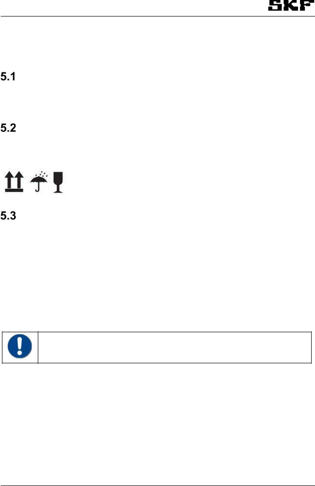
Returns
Clean all parts and pack them properly (i.e. following the regulations of the recipient country) before returning them. Protect the product against mechanical stress (knocks, impacts). Land, sea or air transport can be used for returns. Mark returns on the packaging as follows.
Storage
The products must be stored as follows:
•Store in a closed, dry, dustand vibrationfree place.
•Make sure there are no corrosive, aggressive materials at the place of storage (e. g. UV rays, ozone).
•Protect against pests and animals (insects, rodents, etc.).
•Can be stored in original product packaging.
•Shield the product against heat and cold.
•in case of high temperature fluctuations or high humidity, take adequate measures (e. g. heater) to prevent condensation.
•The product’s acceptable storage temperature range is the same as its operating temperature (see Technical data).
•
Before using the products, inspect them for damage sustained in storage. This applies to parts made of plastic and rubber (embrittlement) as well as components primed with lubricant (ageing) in particular.
FLMONITOR_10K_EN 8.1.2018
15

6 Lubricants
General information
Different lubricants are used in different applications. In order to fulfil their tasks, lubricants must fulfil various requirements to varying extents. The most important requirements for lubricants are:
•Reduction of abrasion and wear
•Corrosion protection
•Noise minimisation
•Protection against contamination and entry of foreign objects
•Cooling (primarily for oils)
•Longevity (physical/chemical stability)
•Compatibility with as wide range of materials as possible
•Meeting economic and ecological goals Immediately
Lubrication selection
SKF considers lubricants to be an element of system design. A suitable lubricant is selected when designing the machine and it forms the basis for centralised lubrication system planning.
The selection is made by the manufacturer/ operator of the machine, preferably together with the lubricant supplier based on a defined requirement profile.
If you have little or no experience with the selection of lubricants for centralised lubrication systems, please contact SKF.
If required, we will be glad to assist customers in selecting suitable components for feeding the selected lubricant and planning and designing their centralised lubrication system.
You will avoid possible costly downtimes caused by damage to your machine/system or the centralised lubrication system.
NOTICE
Only lubricants specified for the product may be used. Unsuitable lubricants may lead to product failure.
NOTICE
Do not mix lubricants. This may result in unforeseeable effects on the usability and therefore on the functionality of the centralised lubrication system.
NOTICE
Due to the multitude of possible additives, it is possible that individual lubricants, which according to the manufacturer's data sheets match the system’s specification, are not in fact suitable for use in centralised lubrication systems (e.g. incompatibility between synthetic lubricants and materials). In order to avoid this, always use lubricants tested by SKF.
FLMONITOR_10K_EN 8.1.2018
16

17

7 General description
SKF Flowline monitor is an oil flow meter unit for controlling and measuring the flow rates of lubricants in oil circulation lubrication systems. The monitor consists of 1 to 10 flow meters depending on the model. The monitor has a local control unit with user’s interface for displaying the flow rates and setting the measuring parameters. Each flow meter has a LED display for indicating the flow status and alarms. The control unit includes a common alarm output relay for connecting the flow alarm information to the customer’s process control system.
The monitor can be equipped with a suitable optional module. The CAN-bus interface is for field bus communication with the customer's process control system and SKF Flowline software. The Relay-CAN module is for versatile common or individual alarm outputs and field bus communication. The mA-output module provides flow rates as 4-20mA analog signals.
8 Design
1. Flow meter
2. Sensor
3. Flow tube
4. Flow valve
5. Control unit
Figure 1 SKF Flowline monitor, main components
SKF Flowline monitor FL15
The SKF Flowline monitor FL15 is designed for 0,1 - 15 l/min flow range. FL15 monitor is comprised of a control unit and a number of flow meters connected to the control unit. There can be 2, 4, 6, 8 or 10 flow meters ( fig. 2).
Figure 2 SKF Flowline monitor FL15 design, with six flow meters
FLMONITOR_10K_EN 8.1.2018
18

SKF Flowline monitor FL50
The SKF Flowline monitor FL50 is designed for 15 - 50 l/min flow range. FL50 monitor is comprised of a control unit, one flow meter connected to the control unit and free flow tube. (fig. 3).
Figure 3 SKF Flowline monitor FL50 design
SKF Flowline monitor FL100
The SKF Flowline monitor FL100 is designed for 50 - 100 l/min flow range. FL100 monitor is comprised of a control unit and two flow meter connected to the control unit (→ fig. 4). There are two flow meters connected in parallel and sum flow is shown in the display.
•
The active right LEDs display the status of the sum flow of two flowmeters.
You could adjust the sum flow from both flow valve.
Sensor´s left LED´s are not ON, only sensor´s right LED´s are ON.
The set alarm limits and the nominal flow are set for the sum flow.
Figure 4 SKF Flowline monitor FL100 design.
FLMONITOR_10K_EN 8.1.2018
19
9 Operation
General
The measuring principle of the all Flowline monitor flow meters are to measure the rotation times of a sensitive lightweight turbine. A special inductive proximity switches in the flow meter senses the metal-coated wings of the turbine.
The control unit in the monitor reads the rotation times of the turbines from the flow meters and calculates the actual flow rate using a pre-programmed formula. The set viscosity grade and measured current temperature are used as parameters in calculation for best accuracy.
The flow meters communicate with the control unit using a bidirectional bus. The control unit reads rotation information from the flow meters and writes LED status to the flow meters according to calculated flow.
In FL50 the oil flows through two parallel flow tubes: main flow tube and side flow tube. Only the flow in side flow tube is measured. The side flow measuring result and main flow are converted to total flow rate in the control unit software. The side flow to be measured is separated from the main flow with an adjusting valve. The adjusting valve affects main flow and side flow synchronically.
In FL100 the oil flows through four parallel flow tubes: two main flow tubes and two side flow tube. Only the flows in side flow tubes are measured. These two side flow measuring results and two main flows are summed in the control unit software to generate the total flow
The monitor includes parameters for controlling the flow rate measurements. There are parameters that are individual for each flow meter (e.g. alarm limits) and parameters that are common for all flow meters in the monitor (e.g. oil viscosity grade). The parameters are set by the user’s interface in the control unit. Refer to section 8.6.
A common alarm relay output is included in all monitors. If more versatile alarm outputs or communication are required, an optional plug-in CAN, Relay-CAN and mA-output modules are available.
The Relay-CAN module enables several alternatives for alarms, for example a separate alarm from each flow meter and several common alarm categories: low, high, pre-alarms and zero flow alarm. It and also CANmodule includes CAN-bus communication for remote monitoring of flow meters by the customer’s process control system or by SKF Flowline software. Communication adapters from CAN-bus to several field buses like Profibus and Modbus are available. An optional analog mA-output module provides an analog interface, which is flexible to connect with other process equipment.
All Flowline monitors include a serial port for communicating with a PC. An optional SKF Flowline software is available which can be used for setting the measuring parameters and for monitoring the flows instead of the local user’s interface.
FLMONITOR_10K_EN 8.1.2018
20
Loading...