


User manual
SKF Dynamic Motor Analyzer
EXP4000

SKF Dynamic Motor Analyzer
EXP4000
User manual
Part number: 71-005 EN Revision: V6
Copyright © 2012 by Baker Instrument Company, an SKF Group Company All rights reserved.
Baker Instrument Company, an SKF Group Company
4812 McMurry Ave. Suite 100 Fort Collins, CO 80525
(970) 282-1200
(970) 282-1010 (FAX)
800-752-8272 (USA Only) http://www.skf.com/group/products/condition-monitoring/electric-motor-testing/index.html
Information furnished in this manual by Baker Instrument Company, an SKF Group Company, is believed to be accurate and reliable. However, Baker Instrument Company, an SKF Group Company, assumes no responsibility for the use of such information or for any infringements of patents or other rights of third parties that may result from its use. No license is granted by implication or otherwise under any patent rights of Baker Instrument Company, an SKF Group Company.
No part of this document may be reproduced in part or in full by any means, such as photocopying, photographs, electronic recording, videotaping, facsimile, and so on without written permission from Baker Instrument Company, an SKF Group Company, Fort Collins, Colorado.
NOTICE
Baker Instrument Company—an SKF Group Company—assumes no liability for damages consequent to the use of this product.
SKF Patents
#US04768380 • #US05679900 • #US05845230 • #US05854553 • #US05992237 • #US06006164 • #US06199422 • #US06202491 • #US06275781 • #US06489884 • #US06513386 • #US06633822 • #US6,789,025 • #US6,792,360 • US 5,633,811 • US 5,870,699 • #WO_03_048714A1

Notices
CAUTION
This equipment has been tested and found to comply with the limits for a Class A digital device, pursuant to Part 15 of the FCC rules. These limits are designed to provide reasonable protection against harmful interference with the equipment is operated in its installation.
This equipment generates, uses, and can radiate radio frequency energy and, if not installed and used in accordance with the product manual, could cause harmful interference to radio communications. If this equipment does cause harmful interference, the user will be required to correct the interference. Due to the phenomena being observed and the material properties being measured, this equipment radiates radio frequency energy while in the active test mode. Care should be taken to ensure this radio frequency energy causes no harm to individuals or other nearby equipment.
Intended use of instrument
The EXP4000 is intended for detection motor efficiency and physical performance deterioration, and other electrical problems within electric machines by trained professionals. It is intended to perform only the specified tests that this manual explains in detail. Please refer to chapters in this manual concerning specific operation of the instrument.
Note on software
While the UNIT is a Microsoft Windows® based instrument, it is specially configured and optimized to perform the functions for which it was designed. The loading or operation of unauthorized software may cause the instrument to malfunction or cease functioning and may void the manufacturer’s warranty.
ii |
Dynamic Motor Analyzer—EXP4000 User Manual |

Notices
Declaration of conformity Manufacturer’s Name & Address:
Baker Electrical Instrument Company, an SKF Group Company 4812 McMurry Ave
Fort Collins, CO 80525 USA
Equipment Description: On-Line Motor Monitor Equipment Model Designations: EXP4000
Application of Council Directive 72/23/EC on the harmonization of the laws related to Member States relating to electrical equipment designed for use within certain voltage limits, as amended by: Council Directive 93/68/EC and Council Directive 2004/108/EC on the approximation of the laws related to Member States relating to the electromagnetic compatibility, as amended by: Council Directive 93/68/EC. Note: due to the phenomena being observed and the material properties being measured, this equipment does radiate radio frequency energy while in the active test mode.
Referenced Safety Standards: EN 61010-1
Referenced EMC Standards: EN 61326:2001
EN 55011 Class A
EN 61000-3-2
EN 61000-3-3
EN 61000-4-2
EN 61000-4-3
EN 61000-4-4
EN 61000-4-5
EN 61000-4-6
EN 61000-4-8
EN 61000-4-11
I, the undersigned, hereby declare that the equipment specified above conforms to the above Directives and Standards.
Signature:
Printed Name: Erik A. Stolz
Title: Electrical Engineer
Dynamic Motor Analyzer—EXP4000 User Manual |
iii |

Notices
Software License Agreement
UNIT—test equipment and desktop versions
Carefully read the following terms and conditions before opening the software envelope or operating the UNIT. Either opening the envelope or using the software constitutes your acceptance of these terms and conditions on behalf of any party using the instrument (the “User”). If you or the User do not agree with these terms, promptly return the instrument with the envelope unopened for a full refund.
1. Definitions
(a)Computer Software: A Software program provided with the Instrument on CD or other physical medium for installation and use on the User’s desktop computer(s) or servers, and all updates, upgrades, enhancements and modifications provided directly or indirectly to the User from time to time.
(b)Documentation: This User Manual and other manuals and documentation relating to the Instrument and provided directly or indirectly to the User in the original Instrument carton or from time to time thereafter.
(c)Instrument: The unit of test equipment with which this User Manual was provided to the User.
(d)Instrument Software: The software program pre-loaded on the Instrument, and all updates, upgrades, enhancements and modifications provided directly or indirectly to the User from time to time.
(e)Software: The Instrument Software and/or Computer Software, as the context requires.
(f)Intellectual Property Rights: All rights arising or protectable under the copyright, trademark, patent, or trade secrets laws of the United States or any other nation, including all rights associated with the protection of computer programs and/or source code.
(g)Person: An individual, a partnership, a company, a corporation, an association, a joint stock company, a trust, a joint venture, an unincorporated organization, or a governmental entity (or any department, agency, or political subdivision thereof).
2. License; Related Terms
(a)Grant of License. SKF grants the User, pursuant to the terms and conditions of this Software License, a non-exclusive, non-transferable, and revocable license to (i) use the Instrument Software only on the Instrument, (ii) the Computer Software(s) on the numbers and types of desktop and/or other computers specified elsewhere in this User Manual, (iii) reproduce the Software only as necessary to use it and create no more than two copies of the Software in machine readable form for back-up purpose only; provided in each case that the copy shall include SKF CMC-Fort Collins (formerly Baker Instrument Company)’s copyright and any other proprietary notices, and (iv) utilize the Documentation only in conjunction with the use of the Software.
(b)Restrictions on Use. The User shall not (i) permit any parent, subsidiaries, affiliated entities or third parties to use the Software; (ii) grant third parties use of the Software on a service bureau, application service provider or other similar basis; (iii) rent, resell, lease, timeshare or lend the Software to any Person; (iv) sublicense, assign, or transfer the Software or this license for the Software to any third party, (v) reproduce the Software other than as expressly authorized herein, or distribute, or publicly display the Software; (vi) make the Software accessible to any Person by any means, including posting on a web site or through other distribution mechanisms over the Internet; (vii) reverse assemble, disassemble, reverse engineer, reverse compile, decompile, or otherwise translate the Software or prepare Derivative Works based on the Software; (viii) place, reproduce, or make available the Software on the User’s computer network if the User is only authorized by this Software License to operate the Software on a single workstation; (ix) exceed at any given
iv Dynamic Motor Analyzer—EXP4000 User Manual

Notices
point in time the total number of network clients authorized by the applicable purchase order or ordering document to use or access the Software; or (x) edit or modify the Software except as expressly authorized by SKF CMC-Fort Collins (formerly Baker Instrument Company), including altering, deleting, or obscuring any proprietary rights notices embedded in or affixed to the Software.
(c)Protection of Software. The User will take action by instruction, written agreement, or otherwise as appropriate with any person permitted access to the Software to enable the User to comply with its obligations hereunder.
(d)Material Terms and Conditions. The User acknowledges that each of the terms and conditions of this Section 2 is material and that failure of the User to comply with these terms and conditions shall constitute sufficient cause for SKF to terminate this Software License and the license granted hereunder immediately and without an opportunity to cure. This subsection 2(d) shall not be construed to preclude, or in any way effect, a finding of materiality with respect to any other provision of this Software License.
3. Ownership
SKF CMC-Fort Collins (formerly Baker Instrument Company), as between SKF and the User, owns all Intellectual Property Rights related to the Software, including custom modifications to the Software, whether made by SKF or any third party. The User agrees that this Software License effects a license, not a sale, of the Software and that the first sale doctrine, as codified in 17 U.S.C. § 109, does not apply to the transaction effected by this Software License.
4. Confidential Information
The Software contains proprietary information, including trade secrets, know-how and confidential information (hereinafter referred to collectively as the “Confidential Information”), that is the exclusive property of SKF CMC-Fort Collins (formerly Baker Instrument Company). During the period this Software License is in effect and at all times after its termination, the User and its employees and agents shall maintain the confidentiality of the Confidential Information and shall not sell, license, publish, display, distribute, disclose or otherwise make available the Confidential Information to any Person nor use the Confidential Information except as authorized by this Software License. The User shall not disclose the Confidential Information concerning the Software, including any flow charts, logic diagrams, user manuals and screens, to persons not an employee of the User without the prior written consent of SKF CMC-Fort Collins (formerly Baker Instrument Company).
5. Limited Warranties; Disclaimer
(a)SKF CMC-Fort Collins (formerly Baker Instrument Company)’s sole and exclusive warranties with respect to the Instrument and Software are set forth in this User Manual.
(b)EXCEPT AS SET FORTH IN THIS User Manual AND TO THE EXTENT PERMITTED BY APPLICABLE LAW, ALL EXPRESS AND/OR IMPLIED WARRANTIES OR CONDITIONS, INCLUDING BUT NOT LIMITED TO IMPLIED WARRANTIES OR CONDITIONS OF MERCHANTABILITY, MERCHANTABILITY OF A COMPUTER PROGRAM, INFORMATIONAL CONTENT, SYSTEM INTEGRATION, FITNESS FOR A PARTICULAR PURPOSE, AND NONINFRINGEMENT, ARE HEREBY DISCLAIMED AND EXCLUDED BY SKF CMC-FORT COLLINS (FORMERLY BAKER INSTRUMENT COMPANY).
6. Limitations on Liability
(a) Limitations and Exclusions. IN NO EVENT WILL SKF BE LIABLE TO LICENSEE FOR ANY DIRECT, INDIRECT, INCIDENTAL, CONSEQUENTIAL, PUNITIVE OR OTHER SPECIAL DAMAGES, LOST PROFITS, OR LOSS OF INFORMATION SUFFERED BY LICENSEE ARISING OUT OF OR RELATED TO THE INSTRUMENT OR THE USE OF THE INSTRUMENT, FOR ALL CAUSES OF ACTION OF ANY KIND (INCLUDING TORT, CONTRACT, NEGLIGENCE, STRICT LIABILITY, BREACH OF WARRANTY OR CONDITION, AND STATUTORY) EVEN IF SKF HAS
Dynamic Motor Analyzer—EXP4000 User Manual |
v |

Notices
BEEN ADVISED OF THE POSSIBILITY OF SUCH DAMAGES. THE PRECEDING EXCLUSION AND DISCLAIMER OF DAMAGES SHALL APPLY TO ALL CLAIMS MADE BY LICENSEE RELATED TO OR ARISING OUT OF LICENSEE’S USE OF THE SOFTWARE, INCLUDING, BUT NOT LIMITED TO, CLAIMS ALLEGING THAT THE SOFTWARE, OR ANY COMPONENT THEREOF, FAILED OF ITS ESSENTIAL PURPOSE OR FAILED IN SOME OTHER RESPECT.
(b) Acknowledgment. The User agrees that the limitations of liability and disclaimers of warranty set forth in this Software License will apply regardless of whether SKF has tendered delivery of the Software or the User has accepted the Software. The User acknowledges that SKF has set its prices and granted the licenses contemplated herein in reliance on the disclaimers of warranty and the limitations and exclusions of liability set forth in this Software License, and that the same form an essential basis of the bargain between the Parties.
7. Term and Termination
(a)Term. The licenses granted herein shall commence on the User’s acceptance of the terms of this Software License, and shall continue in existence until it is terminated in accordance with Section 7(b) below.
(b)Termination. SKF may terminate this Software License and the license conveyed hereunder in the event that the User breaches any provision, term, condition, or limitation set forth in this Software License, including but not limited to the license restrictions set forth in Section 2(b) of this Software License.
(c)Effect of Termination. Within ten (10) days after termination of this Software License and the licenses granted hereunder, the User shall return to SKF CMC-Fort Collins (formerly Baker Instrument Company), at the User’s expense, the Computer Software and all copies thereof, and deliver to SKF a certification, in a writing signed by an officer of the User, that all copies of the Computer Software have been returned to SKF and that the User has complied with the requirements of this Section 7(c).
8. Assignment
The User may assign this Software License in connection with the sale or other transfer of the Instrument, provided, that the transferee agrees in writing to be bound by the terms of this Software License. Except as authorized by the preceding sentence, the User shall not assign or otherwise transfer the Software or this Software License to anyone, including any parent, subsidiaries, affiliated entities or third Parties, or as part of the sale of any portion of its business, or pursuant to any merger, consolidation or reorganization, without SKF CMCFort Collins (formerly Baker Instrument Company)’s prior written consent. Any assignment or transfer effected in violation of this Section 8 shall be void ab initio and of no force or effect.
9. General
The validity and interpretation of this Software License shall be governed by Colorado Law except as to copyright and other proprietary matters, which may be preempted by United States laws and international treaties. In the event of any violation of this Software License, SKF reserves the right to pursue any state law remedies (including contractual remedies) or remedies under federal laws or both. The User consents to exclusive jurisdiction in either state or federal courts in Colorado or both as appropriate and agrees that the prevailing party shall be entitled to its attorney fees and costs. No decision, act or inaction of SKF CMC-Fort Collins (formerly Baker Instrument Company), shall be construed to be a waiver of any right or remedy, and pursuit of any state or federal causes shall not be deemed an election or remedies. In the event of any provision of this Software License shall be deemed unenforceable, or void, or invalid, such provision shall be modified so as to make it valid and enforceable and as so modified the entire agreement shall remain in full force and effect. This Software License sets forth the entire understanding and agreement between the
vi Dynamic Motor Analyzer—EXP4000 User Manual

Notices
parties and no written or oral representative of any kind whatsoever shall in any way modify or expand the terms of this User Manual.
In the event of any conflict or inconsistency between the terms of this Software License and any Documentation, this agreement shall preempt such documentation to the extent inconsistent.
Important notice concerning warranty and repairs
The warranty is void if (i) the UNIT is shipped without shock absorbing packing material, (ii) the UNIT is damaged by improper use, (iii) any party other than SKF modifies the Software or loads or operates unauthorized software programs on the UNIT, or (iv) the User has breached the Software License set forth above. The User assumes all responsibility and expense for removal, reinstallation, freight, or on-site service charges in connection with the foregoing remedies.
SKF CMC-Fort Collins (formerly Baker Instrument Company)’s liability to purchaser relating to the product whether in contract or in part arising out of warranties, representations, instructions, installations, or defects from any cause, shall be limited exclusively to correcting the product and under the conditions as aforesaid.
If the UNIT fails, whether it is under warranty or not, call the SKF service department before returning the unit for repair. If the unit needs in-house repair, our service staff might direct you to ship the unit to the authorized service center closest to you. This might save both time and money. When calling the Baker service department or one of the service centers, please have the model and serial numbers available. These numbers are located on the rear of the instrument. If the unit is out of warranty, a purchase order will be required if the unit is returned for repair.
Virus alert
The UNIT contains computer software that is vulnerable to damage from computer viruses. Before shipping, SKF scanned all data to ensure the UNIT is virus-free. Before inserting any disks into the disk drive or connecting the UNIT to a computer network, scan all disks for viruses.
Trademarks
All other trademarks, service marks or registered trademarks appearing in this manual are the trademarks, service marks or registered trademarks of their respective owners.
Dynamic Motor Analyzer—EXP4000 User Manual |
vii |

Notices
viii Dynamic Motor Analyzer—EXP4000 User Manual
Table of contents |
|
|
1 |
About this manual |
1 |
|
Formatting ............................................................................................................................. |
1 |
|
Information devices............................................................................................................... |
1 |
2 Safety and general operating information |
3 |
|
|
General safety precautions................................................................................................... |
3 |
|
Symbols and labels used on equipment............................................................................. |
3 |
|
Safety warnings..................................................................................................................... |
4 |
|
Operational safety warnings................................................................................................ |
5 |
|
Accessory interconnection and use..................................................................................... |
5 |
|
Cleaning and decontamination............................................................................................ |
5 |
|
Installation requirements..................................................................................................... |
6 |
|
Environment conditions/storage......................................................................................... |
6 |
|
Unpacking the unit................................................................................................................ |
6 |
|
Shipping the unit................................................................................................................... |
6 |
3 |
Getting started |
7 |
|
Configuring software for motor data.................................................................................. |
7 |
|
Database features................................................................................................................ |
7 |
|
EXP4000 software-specific features.................................................................................. |
7 |
|
Starting the software............................................................................................................ |
8 |
|
Test domain buttons............................................................................................................ |
10 |
|
Results panels and windows.............................................................................................. |
10 |
|
Machine tree........................................................................................................................ |
12 |
|
Keyboard shortcuts............................................................................................................. |
13 |
|
Software tips........................................................................................................................ |
13 |
4 |
Connecting the EXP4000 |
15 |
|
Physical setup of EXP4000 with portable sensors......................................................... |
15 |
|
EXP4000 connections to motor terminals....................................................................... |
16 |
|
Connection Setup window.................................................................................................. |
16 |
|
Manual phasor adjustments.............................................................................................. |
18 |
5 |
EXP4000 tests |
19 |
|
Test domains and testing theory....................................................................................... |
19 |
|
Power Quality domain......................................................................................................... |
20 |
|
Harmonics............................................................................................................................ |
25 |

Table of Contents |
|
|
|
Machine Performance domain.......................................................................................... |
26 |
|
Current domain.................................................................................................................... |
31 |
|
Spectrum domain................................................................................................................ |
33 |
|
Torque domain..................................................................................................................... |
37 |
|
Connection domain............................................................................................................. |
40 |
6 |
EXP4000 software overview |
43 |
|
File menu.............................................................................................................................. |
43 |
|
Summary Report................................................................................................................. |
45 |
|
Machine menu..................................................................................................................... |
46 |
|
Thresholds menu ............................................................................................................... |
51 |
|
Tools menu........................................................................................................................... |
54 |
|
Help menu............................................................................................................................ |
64 |
7 |
VFD4000 analysis software option |
65 |
|
Operation details................................................................................................................. |
65 |
|
Waveforms........................................................................................................................... |
66 |
|
VFD Details domain............................................................................................................. |
67 |
8 |
Continuous Monitoring Software option |
69 |
|
File menu.............................................................................................................................. |
70 |
|
Machine menu..................................................................................................................... |
70 |
|
Tools menu........................................................................................................................... |
70 |
|
View menu........................................................................................................................... |
71 |
|
Options menu...................................................................................................................... |
72 |
|
General operation icons...................................................................................................... |
73 |
|
Modifying the continuous monitoring tool....................................................................... |
74 |
|
Channel descriptions........................................................................................................... |
77 |
9 |
Vibration software option |
79 |
|
Viewing results.................................................................................................................... |
82 |
|
Tools to enhance viewing graphs....................................................................................... |
89 |
10 |
DC4000 software overview |
91 |
|
DC4000 Machine Dynamic Analysis software tests and features................................. |
91 |
|
DC4000 Machine Dynamic Analysis software problem types identified...................... |
91 |
|
DC connections for the EXP4000 portable sensors........................................................ |
92 |
|
DC4000 software navigation and overview..................................................................... |
94 |
|
Software testing screen................................................................................................... |
105 |
|
Test domains .................................................................................................................... |
108 |
x |
Dynamic Motor Analyzer—EXP4000 User Manual |
|

Table of Contents |
|
Drive domain..................................................................................................................... |
109 |
Machine domain............................................................................................................... |
116 |
Load................................................................................................................................... |
121 |
Torque ripple..................................................................................................................... |
122 |
Load level .......................................................................................................................... |
123 |
Waveforms........................................................................................................................ |
124 |
Spectrum........................................................................................................................... |
125 |
Harmonics......................................................................................................................... |
128 |
Reports.............................................................................................................................. |
129 |
11 Example test and report generation |
131 |
Motor monitoring ........................................................................................................... |
131 |
Looking at data collected................................................................................................. |
132 |
Creating reports from the report generator................................................................. |
135 |
Automatic generation of reports.................................................................................... |
136 |
Appendix A — Default settings |
137 |
Default settings................................................................................................................. |
137 |
Appendix B — Connection troubleshooting |
139 |
General.............................................................................................................................. |
139 |
Non-VFD mode................................................................................................................ |
139 |
Frequently asked questions............................................................................................. |
140 |
Appendix C — Blue results |
143 |
Appendix D — EP4000 installation |
145 |
What to do first:................................................................................................................ |
145 |
Safety precautions for EP installation............................................................................ |
146 |
Choosing a suitable location for the EP......................................................................... |
147 |
EP4000 ratings................................................................................................................ |
150 |
Appendix E — References and glossary |
151 |
Standards.......................................................................................................................... |
151 |
Literature........................................................................................................................... |
151 |
Glossary of terms............................................................................................................. |
152 |
Appendix F — Technical specifications |
155 |
Index |
159 |
Dynamic Motor Analyzer—EXP4000 User Manual |
xi |

Table of Contents
xii Dynamic Motor Analyzer—EXP4000 User Manual

1About this manual
This manual uses the following conventions in formatting, and informational devices to help you more clearly identify specific elements and information.
Formatting
Interface items are set in Initial Caps and Bold.
Page or window names are set in italics.
File names are set in courier font.
Information devices
Information requiring special attention is set in the following format and structure:
NOTE
Indicates additional information about the related topic that deserves closer attention or provides a tip for using the product.
NOTICE
Indicates information about product usage that can result in difficulty using product, a loss of data, or minor equipment damage if not heeded.
CAUTION
Indicates a hazardous situation with potential for minor to moderate injury or property damage, or moderate to severe damage to the product.
WARNING
Indicates a hazardous situation with risk of serious bodily injury or death.

About this manual
2 |
Dynamic Motor Analyzer—EXP4000 User Manual |

2Safety and general operating information
General safety precautions
The general safety information presented here is for operating and service personnel.
NOTICE
If the equipment is used in any manner not specified by SKF the safety protection provided by the equipment may be impaired.
Symbols and labels used on equipment
Figure 1. EXP 4000 safety labels.

Safety and general operating information
Safety warnings
WARNING
The instrument is not waterproof. Do not allow the opened instrument to be exposed to water. Water in contact with the interior of the instrument compromises protection features and could result in serious injury or death.
Because of the voltages present, testing should be conducted only by trained personnel. Adequate safety precautions must be taken to minimize the risk of serious injust, death, or property damage.
Because of the dangerous currents, voltages, and forces encountered when operating, testing or repairing rotating equipment, safety precautions must be taken for all tests. Follow all safety precautions in this manual and required by your employer. Due to the wide diversity of machine applications, it is impossible to list all general safety precautions. However, this manual includes special safety precautions applicable to the use of the EXP4000.
The maximum rating of the EXP4000 is 1,000 V (500 V for DC operation). 1,000 V (500 V DC operation) is the maximum allowable voltage between any two of the three voltages and the ground clip. Under no circumstances connect the voltage sensing circuit to higher voltage levels. Doing so will cause severe damage to instrument and can seriously injure you.
4 |
Dynamic Motor Analyzer—EXP4000 User Manual |

Safety and general operating information
Operational safety warnings
Any operator of this unit must comply with the following safety precautions:
•Comply with your facility’s safety practices at all times.
•Ensure physical setup does not interfere with your facility’s current or intended operation.
Additionally, operators of this unit must adhere to the following safety precautions to minimize the potential for any dangerous shock hazard conditions:
•Use whatever safety equipment required by your organization, including eye protection, high voltage gloves, arc-flash rated masks, hoods and any required PPC. Prior to opening any Motor Control Cabinet (MCC), ensure that appropriate arc-flash protection clothing is worn.
•Ensure that appropriate lockout / tag-out procedures are properly understood and implemented by all personnel.
•Every connection at MCC must be performed ONLY when rotating system is powered down or off.
•Depending on the kind of test to be run, ensure no one is in close physical proximity to the shaft of the motor or any other moving part of the machinery.
•Do not position motor phase connections near ground or near each other.
•Do not touch the connections, PT’s, CT’s or any component under test while a test is being made.
•This product is grounded through the grounding conductor of the power cord if running on AC power.
•Voltage ground clip must be connected to ground when the unit is running on battery power.
•If you will be running the unit on battery power, ensure that you remove the power cord from the wall outlet and the unit before using.
•Do not coil power cord or test leads near motor leads.
•During repairs, do not substitute any parts. Use only factory-supplied parts.
•This instrument is NOT approved for use in an explosive environment.
Accessory interconnection and use
Several accessories are available for the EXP4000. These accessories are listed in following chapters in the manual. They are to be used only as directed.
Cleaning and decontamination
The EXP4000 should be kept clean and in a dry environment. To clean the unit, wipe with a clean, water-dampened cloth. Do not submerge in water or other cleaners or solvents. To clean the screen, take a soft, water-dampened cloth and gently wipe the surface.
Dynamic Motor Analyzer—EXP4000 User Manual |
5 |

Safety and general operating information
Installation requirements
The unit may be operated flat on its bottom with the lid open. There are no ventilation requirements.
The unit is intended for use in Installation Category II (Portable Equipment), Measurement Category III areas ,and pollution Degree II Environments where occasional non-conducting condensing pollution can be encountered.
Power requirements
Using the provided AC power cord, connect the unit to a grounded AC power source. The unit’s power requirements are 100-240 V AC, 50-60 Hz, 3 A AC maximum current draw.
Environment conditions/storage
The unit is designed for indoor use. If used outdoors, the unit must be protected from rain, snow and other contaminants. Store instrument inside in order to avoid water contamination.
The unit has been tested for use up to 2,000 m altitude.
The tester should only be operated in temperatures ranging from 41 to 104 degrees Fahrenheit (5° C to 40° C). This unit is for use at a maximum relative humidity of 80% for temperatures up to 31 °C decreasing linearly to 50% relative humidity at 40°C.
Unpacking the unit
Carefully remove the following items from the shipping boxes.
•EXP4000
•Power cord
•CTs
•PTs
•Cabling
•User manual
Shipping the unit
The EXP4000 is shipped in factory foam-filled containers. Should the tester need to be returned to SKF, we recommend using the unit’s original packaging or any equivalent casing that meets the following specifications:
•Corrugated cardboard package containers, double-walled, with a minimum burst test of 275 pounds per square inch and,
•Two to three inches of shock-absorbent material surrounding the entire unit.
NOTE
Cardboard, newspapers, and similar materials are not considered good shock absorbers.
6 |
Dynamic Motor Analyzer—EXP4000 User Manual |
3Getting started
Configuring software for motor data
Database management
Database management is highly important in a good predictive maintenance program. It facilitates organization of periodic maintenance data. The database section of the EXP4000 software allows the entry of identifications to help clarify the location of specific motors. It can maintain multiple databases for organization of overall program maintenance. For example, if a facility has two buildings with a number of motor sights in each, it may work best if there were a database created for each building.
Consequences of not organizing data into databases
Since the EXP4000 can be configured to store every test it ever performs, an organized structure is needed to facilitate data integrity and usefulness. Also, creating multiple databases allows easier management of file size and archiving.
Plant maintenance
It is common for plants to have duplicate processes, with identically named motors in each process. (ex: intake pump) This can cause confusion, since the motors are in different locations, but have the same motor ID. Take steps to make motor ID’s unique.
For example, the motor ID for process 1 should be intake pump P1 while the motor ID for process 2 should be intake pump P2.
Database features
The records that are stored by the EXP4000 are linked to each other hierarchically. The principle record, which serves as the base for linking associated records, is the machine ID. Information entered into machine ID and test ID records become part of the database. Like other database information, it can be transferred to other computer programs or other computers.
Navigating the software interface
Familiarity with Windows 98se®, Windows NT SP4®, Windows 2000®, Windows XP®, or Windows 7® and basic computer skills is assumed. Working with the EXP4000 software requires a general understanding of using multiple windows, a variety of keyboard commands, and a pointer device (mouse).
EXP4000 software-specific features
Grey-shaded fields
Gray-shaded fields are generally not editable. Fields with white backgrounds are editable.
Text fields
Text fields are areas that contain editable words or numbers. To edit text fields, press or click in them and type. The software will prompted you for missing information required by the

Getting started
EXP4000 if a necessary field is left blank. This is generally seen when creating or editing motor or machine properties.
Arrows and windows icons
In the EXP4000, arrows serve two functions. They allow you to access information that does not fit on the screen or they allow you to change numbers in a text field. For example, clicking on either the up or down arrow can change a caution threshold for the voltage unbalance test in an electrical test model.
Numeric fields
The two types of numeric fields are input and display. The input fields are required to calculate portion of the result panels or allow entering additional information to the reports. All other numeric fields are display results.
Starting the software
1)To start the EXP4000 software, click on the Explorer icon on the desktop or click on
Start-> All Programs-> Explorer-> Explorer. The Explorer main window appears as shown below.
Figure 1. EXP4000 user interface.
2)When you click on File in the Main toolbar then select a database, the Machine tree populates as shown in the example above.
3)Clicking on a machine in the list populates the rest of the interface as shown.
8 |
Dynamic Motor Analyzer—EXP4000 User Manual |

Getting started
•The Main toolbar, located a the top of the interface, provides the primary controls for access to test and machine information, along with tools used to conduct tests.
•The Machine information bar identifies the current motor or device under test along with the basic nameplate information for the machine.
•The Waveform display provides the primary graphical representation of the waveforms saved for the related measurement. The voltage waveform display can be set to Line to Line or Line to Ground mode via the Options Display tab under the
Tools menu.
•The Test domain buttons provide access to specific test results and indicate the status of test results.
•The Torque time/speed display shows the torque/time measurement acquired in VFD operation mode or the torque/speed measurement acquired in line operation mode.
•The Display phasor icon open a new window showing the Phasor diagram for the related machine.
•Numerical display fields to the left of the Waveform display provide measurements collected for the single phase to neutral voltages or line-to-line voltages (depending on the setting in the Tools Options menu), single-phase currents, average, power factors, average current, total electrical input power and average line-to-line voltage. These fields include:
–– Voltage [V]—average line-to-line voltage.
–– Current [A]—average line current.
–– PF—power factor.
–– V Unbal [%]—voltage unbalance percentage.
–– I Unbal [%]—current unbalance percentage.
•Numerical display fields to the right of the Torque time/speed display provide measurements collected for the motor’s mechanical and electromechanical operating condition. These fields include:
–– Efficiency [%]—efficiency percentage
–– Torque [ft-lb]—motor torque in foot-pounds (or Nm if set to metric).
–– Load [%]—percent load to the motor under test.
–– Load [hp]—energy load to the motor under test.
–– Speed [RPM]—speed of the motor.
•Sensor—portable (internal) or EP (external).
•CTs—current rating of the CTs.
•Auto-Phase—used during line operation to set up the line and current inputs.
•Test date/time dropdown menu and controls— This text field displays the time of the current and previous test data.
NOTE
Pressing the [F1] key on your keyboard opens context help for the window.
Dynamic Motor Analyzer—EXP4000 User Manual |
9 |

Getting started
Test domain buttons
Each test domain button provides access to its specific test results.
Because each threshold equates to a specific color, the software assigns a color to the domain and the testing domain buttons depending on the test result. For example, if the result of the voltage unbalance test falls below the established caution thresholds, the software would assign the color green to the voltage unbalance button.
Results panels and windows
Clicking on any of the test domains opens a test results panel that you can use to select test results to display in a window like the one shown in the example below.
Figure 2. Selecting test results to display using Results panels.
The contents of the results dialog box varies depending on the related test type. Many include two tabs—Result and Trend—as shown in the example above.
Result tab
In this example of the Result tab, we see three main sections.
The Measurement display indicates the severity of the test results compared to the threshold indicators.
10 Dynamic Motor Analyzer—EXP4000 User Manual
Getting started
The Threshold bars display the current threshold level. The threshold is user specified in the electric or vibration models. Each bar has an associated color level:
•Red = warning
•Yellow = caution
•Green = good
•Blue = no applicable threshold
The numeric display in the lower panel presents relevant test result data such as the NEMA percentage derating factor, the percentage load, and amplitudes for the voltage phasors.
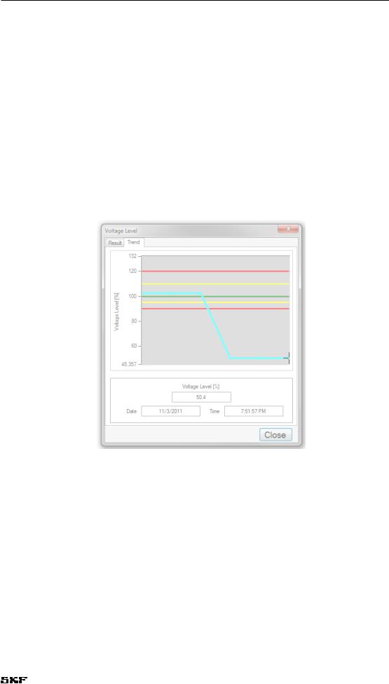
Trend tab
The Trend tab displays trending data for the relevant test. It displays the value of the monitored quantity (y-axis) against the test numbers (x-axis). The x-axis shows the number of measurements performed for that particular motor ID.
Figure 3. Trend tab.
The Trend tab allows you to access specific test results by clicking and holding the left mouse button on the marker and dragging it to a new location. Each test result contains the date and time for the test and important numeric results, which will change to display the new test results data when you release the mouse button.
Dynamic Motor Analyzer—EXP4000 User Manual |
11 |

Getting started
Machine tree
The left panel in the main user interface window is the Machine tree. The highest level is the database name (depicted by a file cabinet icon). Folders are used below each database to store machine test data or other folders. In turn, machines are stored within the folders.
1)Use the plus and minus icons to the left of tree elements to locate the machine that you want to test.
2)Click on the target machine to highlight it. Its name and related nameplate information will appear in the Machine information bar just to the right.
3)Ensure that the EXP4000 is properly connected to the machine.
4)Press Run Electrical to start testing and data collection.
5)Alternatively, you can click on the Tools menu then the Run Electrical item.
Figure 4. Machine tree used to find files and folders for testing.
12 Dynamic Motor Analyzer—EXP4000 User Manual

Getting started
Upgrading databases from previous software versions
Before the EXP4000 software can open a database from previous versions of the software, it must upgrade the database. This upgrade tool will pop up whenever you open a database that can be upgraded. It will place the file in a default directory. This directory must be a separate database from the one where existing data is stored. After the database is upgraded, it will automatically open in the software.
NOTICE
Upgrading a database does not delete the old database. It allows expanded capabilities within the new software to be used, while permitting the use of older versions of software on the old database.
An application is available to automatically update all databases at once. Contact CMC-Fort Collins support for information on obtaining and using this application.
Keyboard shortcuts
•F1 key on the keyboard opens the loaded Help environment.
•F2 key opens the machine properties.
•F3 key operates the New AC Machine function.
•F5 key operates the Run Electrical function.
•F7 key opens the Virtual Scope feature.
•F8 key displays the View Connections function.
•F9 key operates the Transient Analysis Dialog
•Ctrl A – About
•Ctrl M – User Manual
•Ctrl O – Open Database
•Ctrl N – New Database
Software tips
Popup panels require you to immediately interact with dialogs that affect displayed data (loaded or part of a test).
The time required to load a machine with a large number of tests has been decreased by internally connecting or threading the test logs.
When the machine is loaded, but the thread is not completed the message “Test log is Loading” appears instead of the test log graphs. This can cause a perceived lag if you quickly switch machines or delete test results from motors with more than 100 stored tests. This lag time will also be noticeable if you load a machine with a large number of tests and then exit.
At this publishing, we recommend keeping the number of tests per motor to a maximum of 2000.
Dynamic Motor Analyzer—EXP4000 User Manual |
13 |

Getting started
14 Dynamic Motor Analyzer—EXP4000 User Manual

4Connecting the EXP4000
NOTICE
Ensure that all safety warning and procedures have been read and are understood before proceeding with any setup process.
Refer to the “Safety and general operating information” chapter for details.
WARNING
For all connection procedures: to minimize risk of injury or death from electric shock, make sure the motor iis turned off before opening panels or making connections.
NOTE
Make sure the current direction arrow points in the direction of the load when connecting current clamp-ons. Voltage clip-ons and current clamp-ons should be connected to the cold side of the breakers.
Physical setup of EXP4000 with portable sensors
1)Connect the marked voltage clip-ons to the voltage port on the EXP4000.
2)Connect the marked current clamp-ons to the current signal port on the EXP4000.
3)Turn on power to the laptop.
4)Double click the EXP4000 icon to start the program.
Connecting the EXP4000 to the MCC
1)Open the panel of the MCC.
2)Connect a voltage clip-on to each phase of the breaker.
3)Attach one current clamp-on per phase.
Both the current and the voltage sensors of the EXP4000 are designed for low voltage. AC voltage sensors are rated for 1000 VAC. DC voltage sensors are rated for 500 VDC Attach Hall Effect CTs and DC Voltage Sensors for DC Motor testing applications. In order to measure medium or high voltage motors, additional CTs and PTs are required. In this case, the current clamp-ons and voltage clip-ons have to be connected to the CTs and PTs on your site.
4)The voltage clip-ons and current clamp-ons should match color-wise on each phase. Ex. The yellow voltage clip-on should be attached to the same phase as the yellow current clamp-on.
Connecting the EXP4000
EXP4000 connections to motor terminals
1)Connect the current clamp-ons and voltage clip-ons to the terminal box.
2)The voltage clip-ons and current clamp-ons should match color-wise on each phase; for example, the yellow voltage clip-on should be attached to the same phase as the yellow current clamp-on.
3)Attach one voltage sensor to each phase.
4)Exercise extreme caution to make sure that no terminals or clip-ons touch each other or touch ground when energized.
5)Prior to energizing the motor, exercise extreme caution to make sure that no terminals or clip-ons touch each other or touch ground. Energize the motor.
Physical setup of the EXP4000 with EPs
See Appendix D for installation instructions for EPs.
1)Connect the EXP4000 end of the mixed AD cable to the MCC port on the EXP4000.
2)Connect the other end of the mixed AD cable to the MCC plug.
3)Set the Sensors option of the main panel to EP.
4)Click on Run Electrical.
Connection Setup window
When performing an electrical test on a line operated motor, one of two warnings can appear. The first warning will appear if the Auto-Phase feature is not activated (box checked in the main window), and the EXP4000 realizes that the connection is mistaken (for example, having the current and voltage connections being in acb and abc sequence, respectively). The second warning will appear if Auto-Phase has failed due to excessive unbalances on the measured currents or voltages. This can be from lacking one voltage signal, not having properly closed a CT.
Clicking on Yes will take you into the connection setup wizard. Clicking on Continue Test will continue testing using the physical setup. Clicking on Abort Test will stop the test without saving any information to the database.
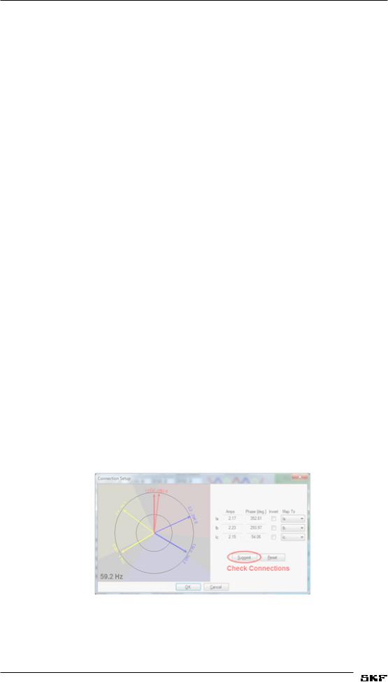
Setup wizard/suggest button
Figure 5. Connection Setup window showing Suggest button.
When the connection setup wizard appears the Suggest button is available. The Suggest button’s purpose is to offer reasonable solutions in error mitigation. If there is more that one
16 Dynamic Motor Analyzer—EXP4000 User Manual
 Loading...