

Singer 312U141 Service Manual

SERVICE
MANUAL
SINGER
Copyright'^ 1977THE
AllRights Reserved Throughout the World
SINGER
COMPANY
H N D E X=
Specifications 2
Partsofthe
machine
head
2
I. Preparation
1). Placeof installation of machine 3
2). Howto mount the machinehead
3). How to mount the motor 3
4). Howto connect the motor to the treadle 3
5). How to mount the bobbin winder assembly 3
6). Howto mount andadjustthekneelifterand
For
Installation OfMachine.
•'
accessories
II. Lubrication Before Starting To Sew.
1).Oiltypeand oil
2). Adjustmentfor lubrication 7
3). Precautionbefore startingto sew 7
III. Preparation
1). Selection of thread 8
2), Howto insert the needles 8
3). Methodof threadingthe upper thread 8
4). How to windthe lower thread on the bobbin 9
5).
How
6).
IV.
2),After
V.
4). Proper
to adjustthe
How
to placethe bobbininto the hook 10
HowToOperate.
1). Start
sewing
sewing
Stitch
1).
Adjustment
2).
Adjustment
Adjustmentoffeed
3).
5),Proper
6).
Relative
Positionsoffeed
7).
8). Relative positionoffeed dog and needles
reservoirs
For
Operation.
bobbin
Adjustment.
of stitch
of thread
timing
timing
positions
length
tension
dog
between
of the hookand take up
of thehookandthe
regulator
winder
assembly
height
and
thehook and
pressure
needle
lever
opener
foot
presser
3
4
6
9
H
11
12
12
15
16
18
18
18
VI.
Qeaning
1).
Cleaning
2).
Lubrication
And
Lubrication.
20
Specifications
t
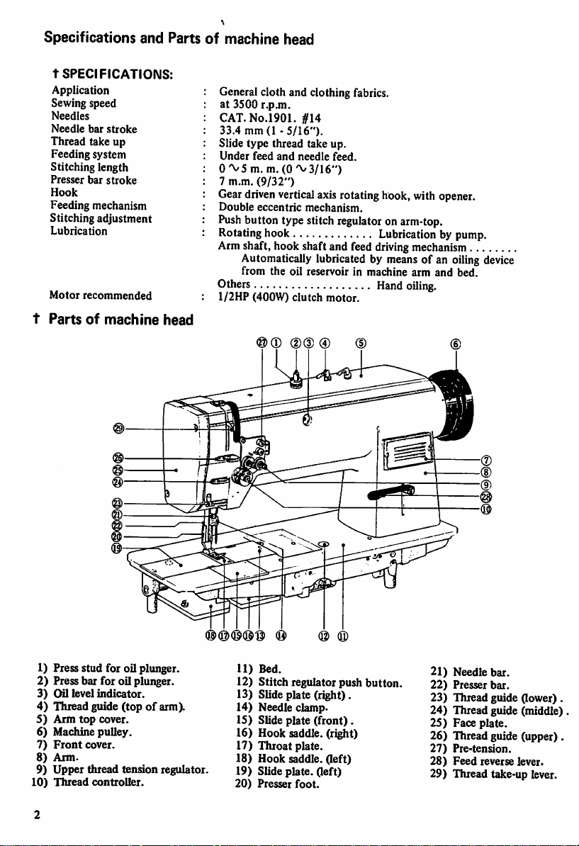
SPECIFICATIONS:
Application
Sewing speed
Needles
Needle
bar
Thread take up
Feeding
system
Stitching length
Presser
bar
Hook
Feeding mechanism
Stitching adjustment
Lubrication
Motor
t
Partsofmachine
stroke
recommended
stroke
and
Partsofmachine
head
head
Generalcloth and clothing fabrics,
at 3500
r.pjn.
CAT.No.1901.
33.4 mm (1 -
Slide type thread take up.
Under
feed
O'VS
m. m.
7
m.m.
(9/32")
Gear
driven
Double
eccentric
Push
button type stitch regulator on arm-top.
Rotating hook
Armshaft, hook shaft and feed drivingmechanism
Automatically lubricated by meansof an oilingdevice
from
Others Hand
1/2HP
(400W)
@(D
#14
5/16").
and
needle
(0'\/3/16")
vertical
mechanism.
the
oil reservoir in
clutch
(D®
feed.
axisrotatinghook, with opener.
Lubricationbypump.
machine
arm
and
bed.
oiling.
motor.
@ ®
1) Press stud for oil plunger.
2) Press bar for oil plunger.
3)
Oil level
4)
Thread guide
5)
Arm
6) Machine
7)
Front
8)
Arm.
9)
Upper
10)
Thread
indicator.
top
cover.
pulley.
cover.
thread
controller.
(topofarm).
tension
regulator.
(SxS)®®®
11)
® (8)
Bed.
12) Stitch regulator push
13) Slide plate (right).
14) Needle
15) Slide plate
16) Hook saddle, (right)
17)
Throat
18) Hook saddle, (left)
19) Slide plate, (left)
20)
Presser
clamp>
(front).
plate.
foot.
(0)
button.
21) Needle
22)
Presser
bar.
bar.
23) Thread guide (lower) .
24)
Thread guide (middle)
25)
Face
plate.
26) Thread guide (upper) .
27)
Pre-tension.
28)
Feed
reverse lever.
29) Thread take-up lever.
.
PREPARATION
MACHINE.
1.
PLACE
CHINE.
In
order
OF
to ensure
machine at high speed
machine
shouldbesetona
FOR
INSTALLATION
INSTALLATION
smooth
operationofyour
without
level
OF
vibration, the
floor.
Preparation for installation of machine
OF
MA
HOWTOMOUNT
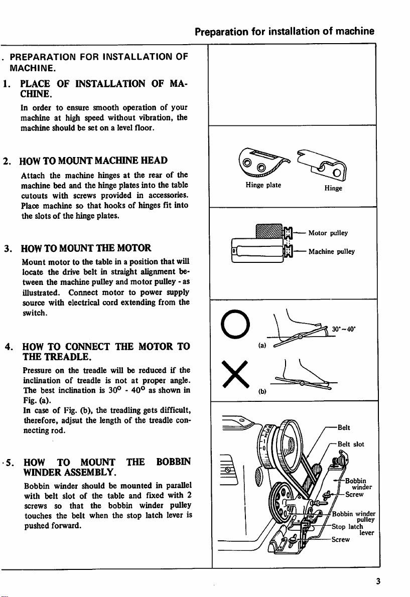
Attach
the machine hinges at the rearofthe
MACHINE
HEAD
machine bed and the hinge plates into the table
cutouts with screws provided in accessories.
Place machine so
the
slotsofthe
HOWTO MOUNT
Mount
motortothe
locate
the
tween the machine pulley and
illustrated.
source
with
switch.
HOW
TO
THE
TREADLE.
Pressure
inclinationoftreadle is
The
on
best
that
hooksofhinges fit
hinge plates.
THE
MOTOR
drive
belt
in straight alignment be
Connect
electrical
CONNECT
the
motortopower
cord
extending
THE
treadle
willbereducedifthe
notatproper
inclinationis30°-40°asshown
table in a position
motor
MOTOR
that
pulley - as
supply
from
angle.
into
will
Fig. (a).
In caseofFig. (b),
the
treadling
gets
difficult,
therefore, adjsut the lengthofthe treadle con
necting
rod.
the
TO
Hinge
plate
—
Motor
pulley
jjfj
Machine
•C
in
pulley
30*-40*
Belt
slot
HOW
WINDER
Bobbin
with
screws so
TO
winder
belt
MOUNT
ASSEMBLY.
shouldbemounted
slotofthe
that
the
table
bobbin
THE
and
fixed
winder
BOBBIN
in parallel
with
pulley
touches the belt when the stop latch lever is
pushed
forward.
Bobbin
2
f^-ZBobbin
winder
Stop
Screw
latch
winder
pulley
lever
/
Preparation
.
HOW
KNEE
.
KNEE
The
presser
promote
for
installationofmachine
TO
MOUNT
LIFTER
LIFTER
knee
bar.
AND
MECHANISM.
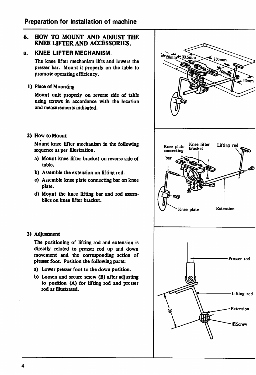
lifter
mechanism
Mountitproperlyonthe
operating efficiency.
AND
ADJUST
ACCESSORIES.
lifts
and
1) PlaceofMounting
Mount
unit
using screws in accordance
and
measurements
2)
HowtoMount
properly on reverse sideoftable
with
the
indicated.
Mount knee lifter mechanism in the following
sequence as
a)
Mount
table.
per
knee
illustration.
lifter
bracketonreverse
b) Assemble the extension on lifting rod.
bar
bar
and
c) Assemble knee plate connecting
plate.
d) Mount the knee lifting
bliesonknee
lifter
bracket.
lowers
table to
location
on knee
rod
THE
the
side
assem
•^28mm^33.5nim
Knee
plate
connecting
of
Efki"'"
105mm
Knee plate Extension
3)
Adjustment
The positioningoflifting rod and extension is
directly related to presser rod up and down
movement
pfesser
a)
b) Loosen
rodasillustrated.
foot.
Lower
poation
to
and
the
Position
presser
foottothe
and
secure screw (B)
(A) for lifting rod
corresponding
the
following
down
after
action
parts:
position.
adjusting
and
presser
of
Presser
Lifting
Extension
(BScrew
rod
rod

c)
Loosen
screw
4)
Placing die
adjust
tighten
the
lifting
screw
Stopper
(C)ofknee
rod
after
Pin
lifter
for
proper
adjustment.
a) Loosen set screw (D)ofstopper
b) Move knee plate to the right so
foot
lifts to its highest
c)
Tighten
set
screw (D).
NOTE
After
this adjustment, stopper pin should
contact
part
(A)ofknee
5)
PositionofKnee
Adjust
knee
plate
postureofoperator
cal
comfortable
b.
OIL
Position oil
as
not
secure oil
c.
VIBRATION-PREVENTING
PAN
to interfere
pan
position
pan
to table using nails.
The vibration-preventing
stabilize the machine
smooth
operation.
comersofthe
as
follows.
1) Make
mm
tableasshowninthe
spot
facingof20
depthatthe
Be suretogive
Plate
in accordance
on reverse sideoftable
portion
lifter
to provide for
then
tighten
with
knee lifter operation,
rubber
and
Fit
thereby to provide
these
rubbersatAe
mm radius
four
cornersofthe
smooth
facingtoface A.
bracket.
with
RUBBER
2) Nail the vibration-preventing rubbers down
at
the
four
cornersofthe
tableasshown
Fig.
bracket
and
inclination;
pin.
that
presser
(12.7
mm).
the
physi
the
most
screw (E).
cut-out
is used to
four
illustration
and
table.
Preparation
13
in
Knee
Vibration
preventing
plate
5.5%
for
installationofmachine
Lifting
Knee
lifter
bracket
Nail
rubber
®
Extension
Screw
rod
Stepper
Screw
Screw
13%
pin
Lubrication
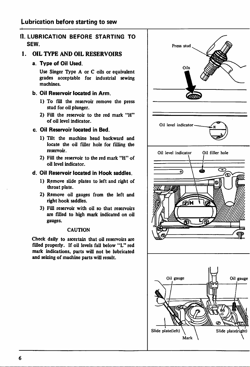
11.
LUBRICATION
SEW.
1.
OIL
TYPE
a.
TypeofOil
Use Singer
grades
machines.
b.
Oil
Reservoir
1) To fill the reservoir remove the press
stud
2)
Fill
of
c.
Oil
Reservoir
1)
Tilt
locate the oil filler hole for filling the
reservoir.
2)
Fill
oil
d.
Oil
Reservoir
1) Remove slide plates to left and right
throat
2) Remove oil gauges from the left and
right
3)
Fill
are filled to high mark indicated on oil
gauges.
Check
dailytoascertain
filled
properly.Ifoil levels fall
mark
indications,
and seizingofmachine
before
AND
Type
acceptable
for
oil plunger.
the
reservoirtothe
oil
level
the
machine
the
reservoirtothe
level
indicator.
plate.
hook
reservoir
CAUTION
startingtosew
BEFORE
OIL
Used.
locatedinArm.
indicator.
locatedinBed.
locatedInHook
saddles.
parts
STARTING
RESERVOIRS
A or C oils or equivalent
for
industrial sewing
red
mark
head
backward
red
mark
with
oilsothat
that
oil reservoirs are
below
will
notbelubricated
parts
will result.
TO
"H"
and
"H"
saddles.
reservoirs
"L"
red
Press
stud
Oil
level
indicator
Oil
level
indicator
Oil
filler
hole
of
of
Slide
Oil
gauge
plate(left)
Mark
Slide
Oil
gauge
plate(right)
\
 Loading...