

Page 1
DP200/DP102
DP201
/
DP202
2X
/
2X DP303
1X
/
1X DP302
3DWOX 1
Read the User Manual before operating the product,
and keep the manual at a convenient place near the
product.
3DWOX Desktop Manual
3dprinter.sindoh.com
Page 2

2
Contents
1. Basic UI Elements --------------------------------------------------------------------------------------------------------------
4
2. Functions and Information --------------------------------------------------------------------------------------------------
6
2.1 Loading -----------------------------------------------------------------------------------------------------------------------------
6
Detail description -----------------------------------------------------------------------------------------------------------------
6
2.2 Profile Value Setting -------------------------------------------------------------------------------------------------------------
6
Detail description -----------------------------------------------------------------------------------------------------------------
6
2.3 Custom Profile ------------------------------------------------------------------------------------------------------------------
11
2.4 Filament Information Indicator ----------------------------------------------------------------------------------------------
13
Detail description ---------------------------------------------------------------------------------------------------------------
13
2.5 View Mode Selection Button -------------------------------------------------------------------------------------------------
13
Detail description ---------------------------------------------------------------------------------------------------------------
14
2.6 Moving a model ----------------------------------------------------------------------------------------------------------------
14
2.7 Adjusting Model Size ----------------------------------------------------------------------------------------------------------
15
2.8 Model Rotation -----------------------------------------------------------------------------------------------------------------
15
2.9 Print -------------------------------------------------------------------------------------------------------------------------------
15
2.10 Standard Menu Bar ------------------------------------------------------------------------------------------------------------
15
2.11 Select a Cartridge --------------------------------------------------------------------------------------------------------------
16
2.12 Equal Distribution --------------------------------------------------------------------------------------------------------------
18
2.13 Merge & Split --------------------------------------------------------------------------------------------------------------------
19
Merge ----------------------------------------------------------------------------------------------------------------------------
19
Split --------------------------------------------------------------------------------------------------------------------------------
19
Detail description --------------------------------------------------------------------------------------------------------------
19
3. Printing (basic functions) -------------------------------------------------------------------------------------------------
26
3.1 Loading 3D Model Files ------------------------------------------------------------------------------------------------------
26
3.2 Basic Parameter Setting ------------------------------------------------------------------------------------------------------
26
3.3 Slicing -----------------------------------------------------------------------------------------------------------------------------
26
3.4 Print --------------------------------------------------------------------------------------------------------------------------------
27
USB Thumbdrive ----------------------------------------------------------------------------------------------------------------
27
Network Connection -----------------------------------------------------------------------------------------------------------
27
Local Network Usage ----------------------------------------------------------------------------------------------------------
28
4. Advanced Features ----------------------------------------------------------------------------------------------------------
30
4.1 Support Edit Function ---------------------------------------------------------------------------------------------------------
30
Support Editing View Mode -------------------------------------------------------------------------------------------------
30
4.2 3D Model Analysis Function ------------------------------------------------------------------------------------------------
33
Select 3D Model ----------------------------------------------------------------------------------------------------------------
33
Under Analysis menu, select Thickness / Overhang. -----------------------------------------------------------------
34
Analysis Control Window ----------------------------------------------------------------------------------------------------
34
Thickness Analysis Function ------------------------------------------------------------------------------------------------
34
Overhang Analysis Function ------------------------------------------------------------------------------------------------
35
Page 3

3
4.3 Function to Calculate Optimal Printing Direction ----------------------------------------------------------------------
35
Estimated Printing Error Surface -------------------------------------------------------------------------------------------
35
Overhang Surface -------------------------------------------------------------------------------------------------------------
35
Amount of Support -------------------------------------------------------------------------------------------------------------
35
Page 4
4
1. Basic UI Elements
Reference
- Font used in the printer GUI and the user manual is the “NANUM” font provided by NAVER.
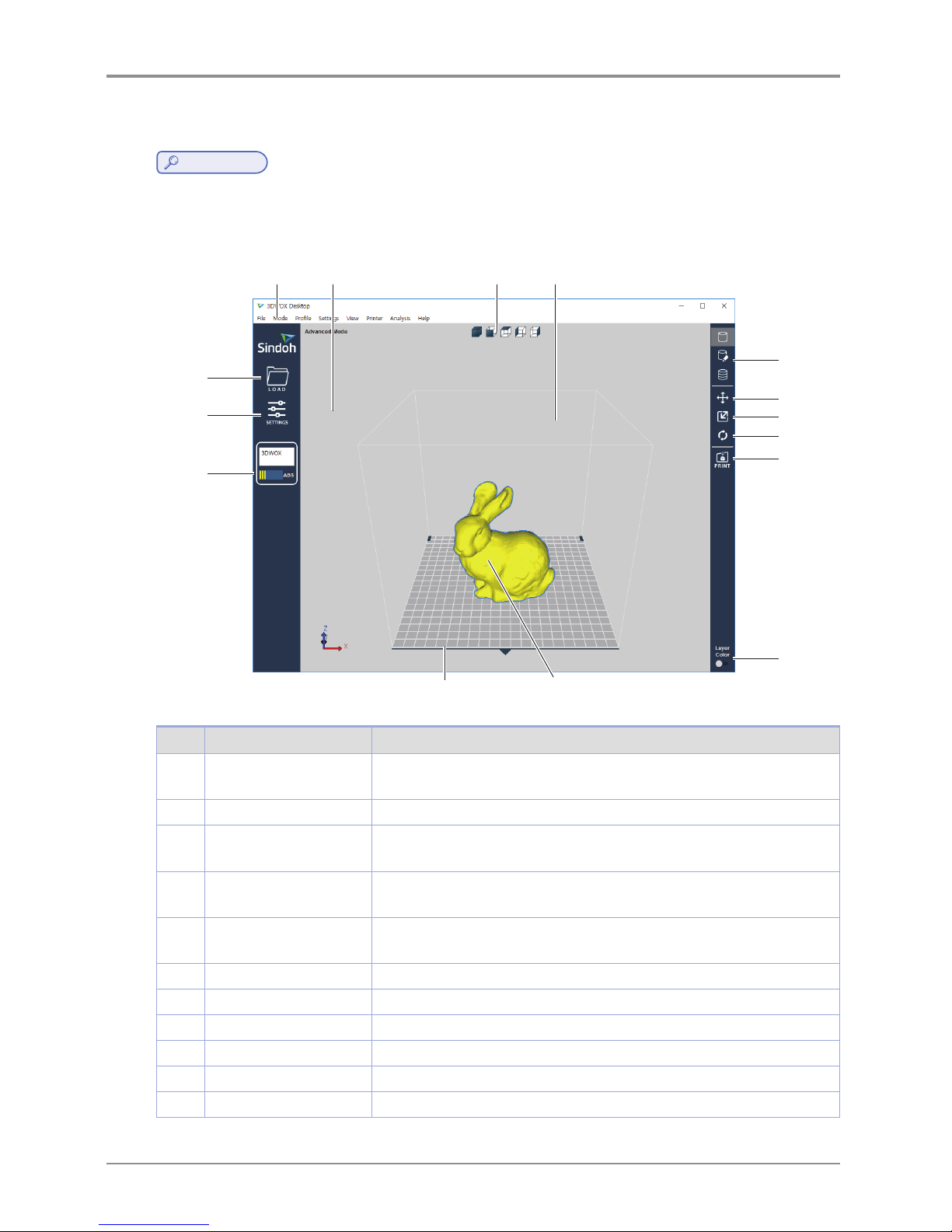
After installation is complete, double click on the icon created on your desktop, a screen similar to the following
appears. Explanation is as follows.
1 2 3
4
5
6
7
8
9
10
11 12
13
14
15
No. Name Explanation
1 Standard menu bar Most program functions are available in this menu bar. Opening files,Loading
preset values, Exporting program values and more functions available.
2 3D view Displays a reconstructed 3D model loaded on the program.
3 Select view angles You may look at the three-dimensional view from the front, back, left, right,
up, and down based on the selected angle.
4 Printer Domain In 3D view, displays actual printer domain showing the location and size of
the model.
5 View Mode Selection
button
On the screen 3 types of viewing modes are available. 3D Model Viewer,
Support Edit Viewer, Layer Viewer are available.
6 Position button Moves model in direction of 2 axes.
7 Scale button Changes the model’s size. (zoom or change length)
8 Rotation button Rotates object on set angles based on 3 axis.
9 Print button Connects to a printer to print a sliced model over the network.
10 Layer Color button Select colors to print by layers.
11 Printer frontal indication Indicates the front of the printout.
Page 5
5
No. Name Explanation
12 3D model 3D model data displayed on the screen.
13 Import button (LOAD) Loads printable 3D data into program.
14 Settings button Settings for values necessary for slicing.
15 Filament information
indicator
Shows information on filaments inside the printer. Easily informs user of
filament material, color and remaining quantity.
2X and 2X DP303 display two bars when both cartridges are loaded.
16 (2X/2X DP303
)
No. Name Explanation
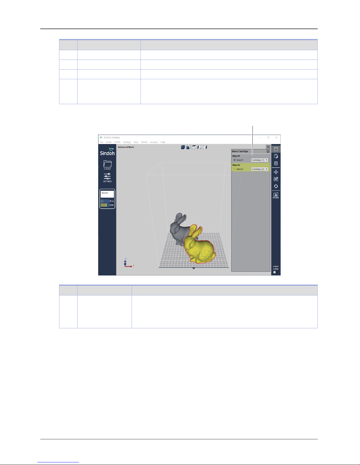
16 Select a Cartridge
button
It is enabled only for the 2X and 2X DP303. Loaded cartridges will be displayed .
If two or more objects are loaded, additional lines with cartridge selection options
will be displayed.
Cartridges can be selected and printed according to each mesh or object.
Page 6
6
2. Functions and Information
2.1 Loading
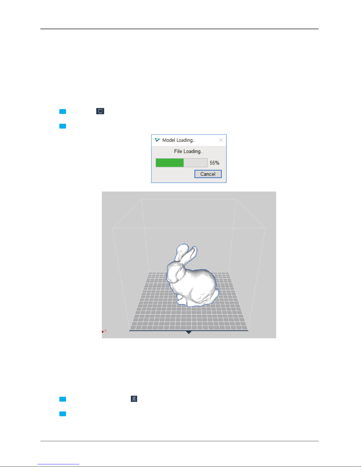
Loads a printable 3D model and displays it on the screen.
Currently supported file formats are ply, obj, stl (binary, ascii, amf)
Detail description
1 Click on the
Import button located left of screen.
2 After selecting file, 3D model file is displayed as if it’s on the printer bed.
2.2 ProleValueSetting
Slicing and printing require variety of parameter values. From the material of the filament, to the height of the
sliced layers, and to the printing speed, various parameters should be configured.
Detail description
1 Click on the Settings button
located on left bar.
2 According to selected mode a window will pop up, user can input desired profile.
Page 7
7
Easy Mode
-
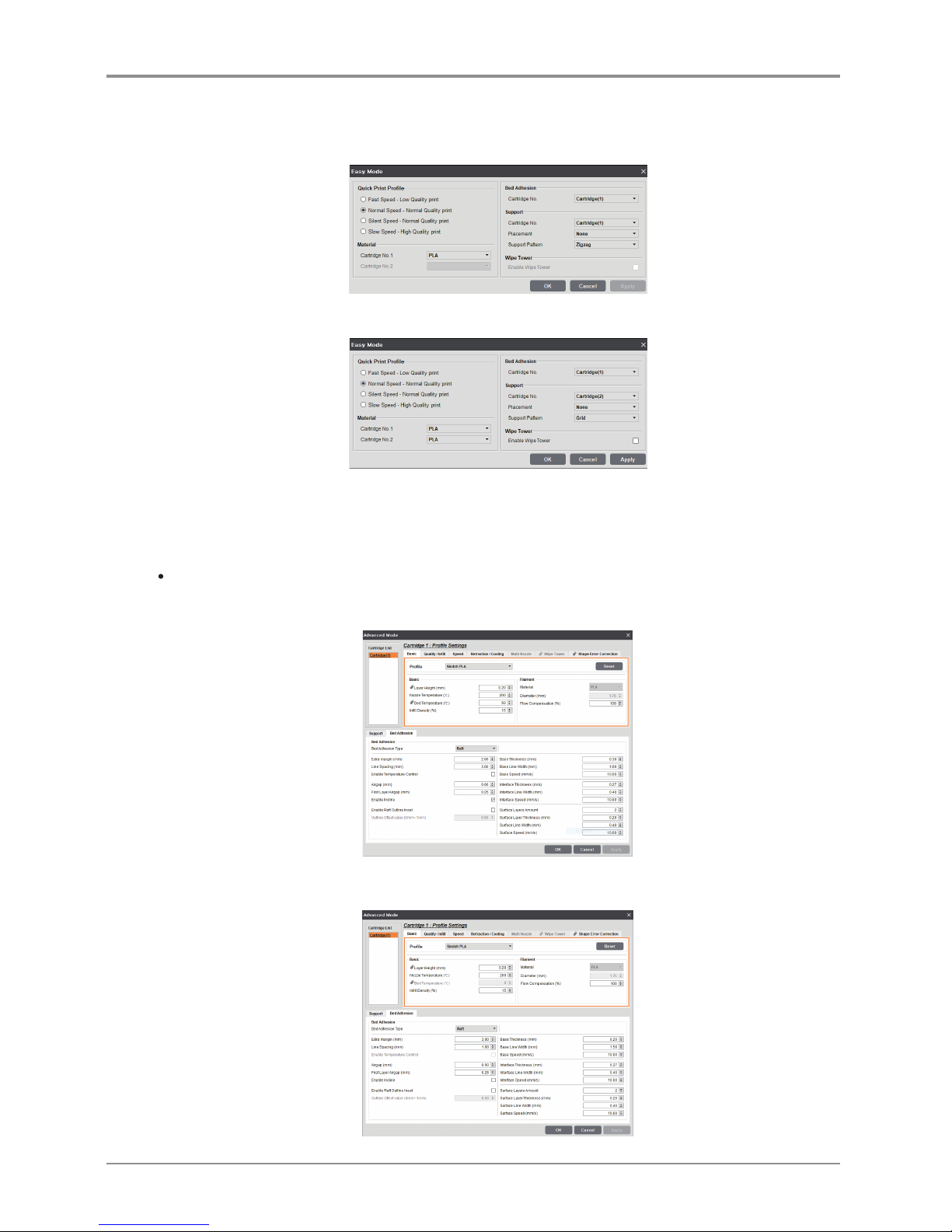
Easy mode can be set for printing speed-quality, material, support pattern, and inside filling.
-
For the 2X and 2X DP303, Cartridge No. is enabled.
Advanced Mode
-
This enables the user to change profiles to modify output values as he/she desires.
-
Custom profiles (= user-defined profiles) can also be edited in the advanced mode. (See 2.3 Custom Profile.)
Basic
<This applies to the default profiles of the slicer program.>
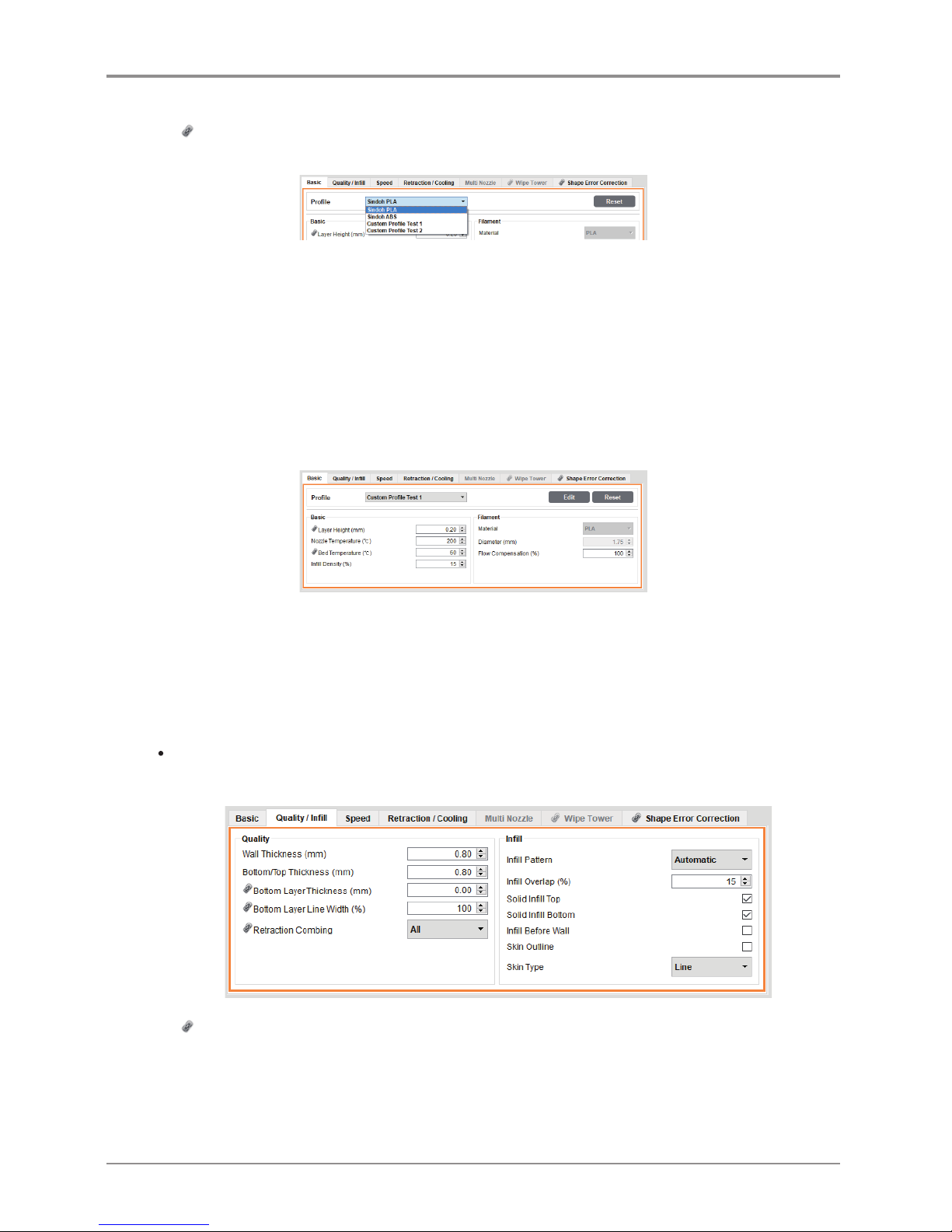
- For the DP 201, DP 201 bed temperature and material settings are disabled.
Page 8
8
- For the 2X or 2X DP303, two cartridges will be on the list, and each cartridge can be set individually.
-
sign marked values are synchronized for two cartridges. Individual values cannot be set independently.
-
Support type can be selected or disabled.
-
Profile selection bar: The user may choose either a default profile or a custom profile.
-
Reset button: Clicking the “Reset” button will restore the current setting before the new setting is saved
(before the “OK” or the “Apply” button is clicked).
However, the “Creation Position” in the “Support” tab and the “Bed Fixation Type” in
the “Bed Fixation” tab will be retained even after the “Reset” button is clicked.
-
OK button: This will save all the setting values and close the dialog box.
-
Apply button: This will save the setting values without closing the window.
-
Cancel button: This will close the dialog box without saving the setting values.
<This applies to custom profiles (not the default profiles of the slicer program).>
-
“Edit” button: If the user clicks this button, the changes in the “Edit Custom Profile” will be saved,
and the user will return to the advanced mode, where the changes will also be reflected.
If the user does not save the changes in the “Edit Custom Profile”, the changes will not be reflected
in the advanced mode.
-
The other settings will be identical to those of the default profile.
Quality / Infill
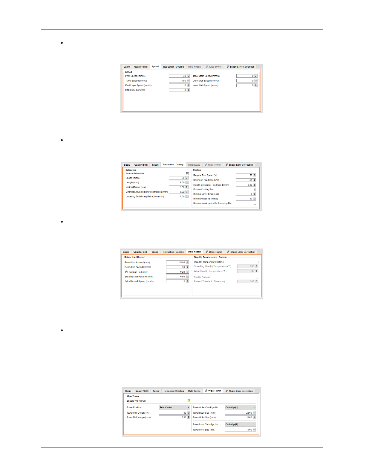
- Sets values for thickness and infill rate of external walls and bottom/top surface of the model .
-
sign marked values are synchronized for two cartridges.
Individual values cannot be set independently.
Page 9
9
Speed
- It controls the printing and travel speeds.
- If you print large object with a high “Fill Density”, please reduce the “Travel Speed”.
Retraction / Cooling
- Sets control values for the retraction of filament and nozzle cooling fan.
Multi Nozzle
- It is enabled only for the 2X or 2X DP303.
-
It is a window to set profile when using multiple nozzles.
- For outputting a large printout with the multi-nozzle, set the lowering bed value to be larger (0.8 mm
recommended) than the default value (0.2 mm).
Wipe Tower
-
It is enabled only for the 2X and 2X DP303. This feature is recommended for use when printing
on one layer with two cartridges.
1. While using other nozzle, wipe off any leaking filament residue from the waiting nozzle to maintain a
smooth output surface.
2. When the nozzle is replaced, the filament is first output to the Wipe tower to compensate for
the filaments leaked from the nozzle.
Page 10
10
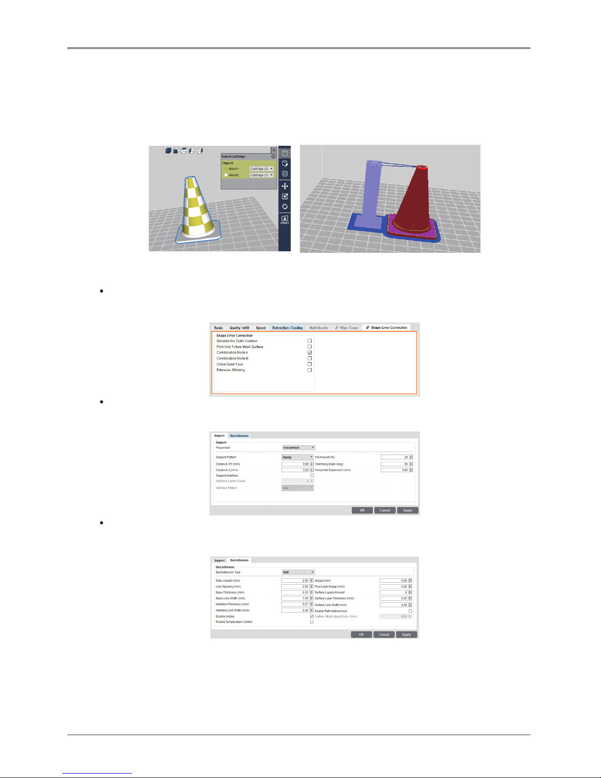
- The Wipe Tower is divided into an Inner tower and an Outer tower, and one cartridge can be used in the
tower of each part.
For example, if you set the outer cartridges to (1) as shown, the inner tower will automatically be set to
cartridge (2).
-
In order to ensure a stable Wipe tower output, please enlarge the tower raft and tower size according
to the size of the shape you want to output.
- Select [Advanced Mode]-[Enable Wipe Tower] and [Layer Viewer] to show the Wipe Tower.
Shape Error Correction
- Shape error correction provides functions to correct mesh errors. (Ex: Printing along the mesh surface).
Support
- It is used to set the position and pattern of support.
Bed Adhesion
- It tab enables setting according to assigned fixing type.
-
Please set the bed adhesion type to [Brim] if the flexible filament is used to print a model with narrow
bottom. Otherwise, the output will not stick to the bed or warp.
-
In outputting a printout of large volume with a filament made of ABS material, the printout and the raft may
separate from each other because the printout is shrunk during the outputting. In such case, decrease the
“First Layer Airgap” or increase the “Flow Compensation” ([Basic]) before outputting the printout.
Page 11
11
2.3 CustomProle
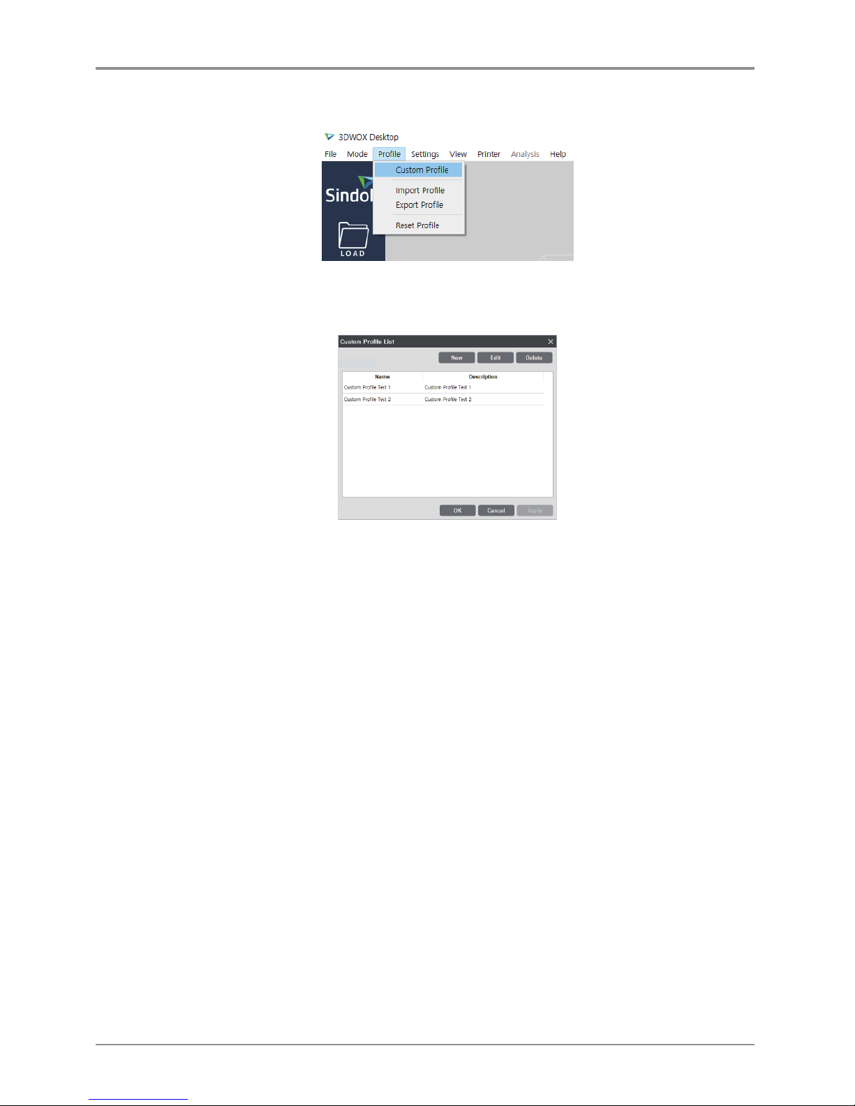
Clicking [Profile] - [Custom Profile] will open the [Custom Profile List] window.
Only custom profiles that are exclusive of the slicer program’s default profiles will be listed.
If the user has not created a custom profile, the list will be empty.
* Name: This is the profile name input by the user for profile creation.
* Description: This is the description of the profile input by the user.
- The description may be edited by double-clicking the button on the [Custom Profile List] window.
(Enter after editing) The changes will be saved when the user clicks the “OK” or “Apply” button.
* [New] button: This button enables the inputting of a new custom profile.
- When this button is clicked, the [Add Custom Profile] window will appear.
* [Edit] button: This button enables the editing of an existing custom profile.
- When editing, the user should select one custom profile at a time.
- When this button is clicked, the [Edit Custom Profile] window will appear.
* [Delete] button: This button enables the deletion of an existing custom profile.
- A deletion will only be saved when the user clicks the “OK” or “Apply” button.
- The user may select and delete multiple profiles at a time.
Page 12
12
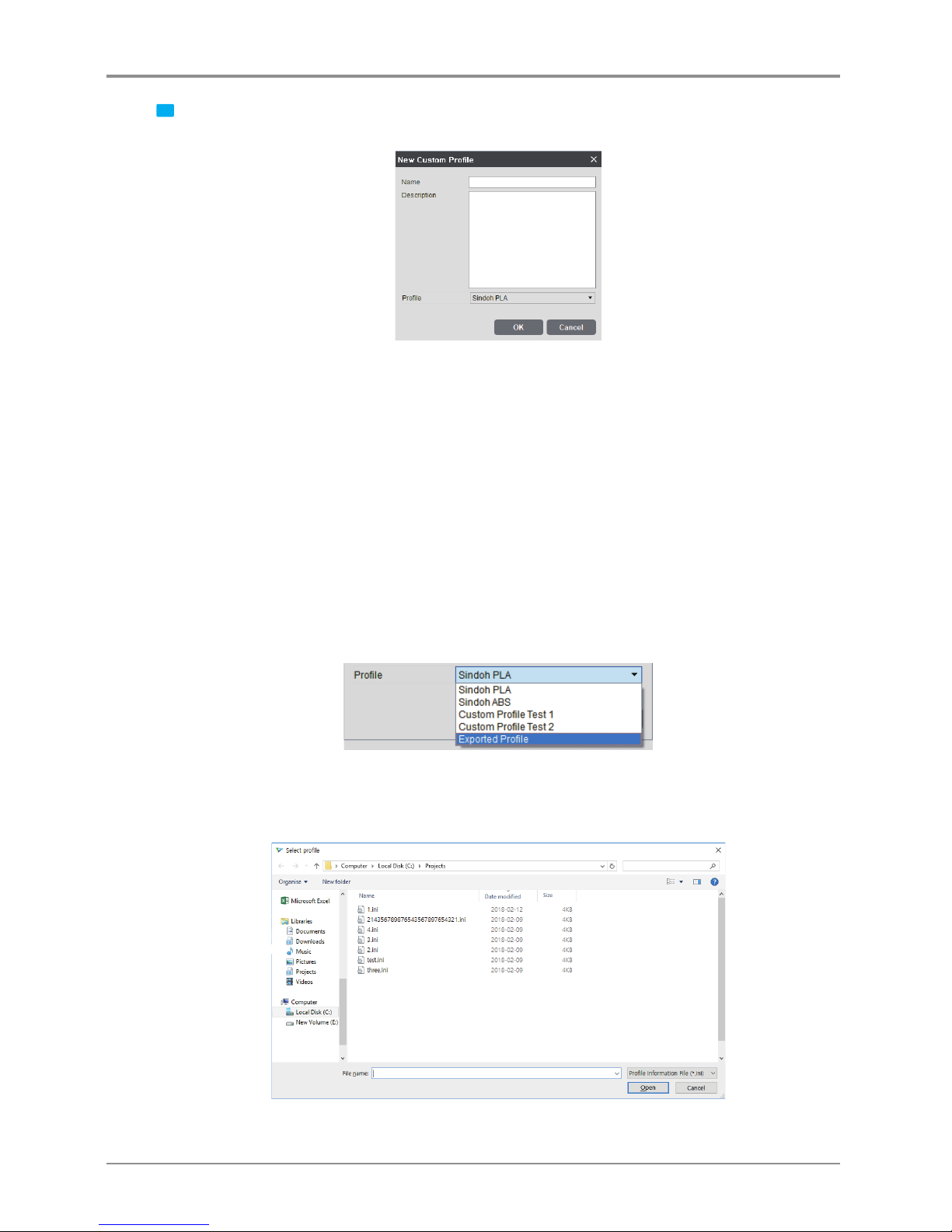
1 Clicking the [New] button → [New Custom Profile] window
- This window is for the creation of a new custom profile.
* Name (required value): Input a profile name with a maximum length of 30 characters.
- The symbols ?, “, *, \, /, |, :, <, >, [ , and ] cannot be entered in the custom profile name.
* Description (optional value): Input a profile description with a maximum length of 300 characters.
* Profile (required value): Select the profile number to be imported.
- The user may copy not only a default profile but also a previous custom profile that he/she has created.
- The list of default profiles varies depending on the model.
e.g., In the case of the DP200, when no custom profile is defined, only the “Sindoh PLA” and the
“Sindoh ABS” will be listed.
- In the case of tthe 3DWOX 1, 2X/2X DP303 and 1X/1X DP302 model, the [New Custom Profile] window
will show the “ETC” profile.
In profile editing, if the user selects a Sindoh profile, he/she can select only profile values within the
limits given by Sindoh.
However, if the user selects “ETC”, he/she can select a wider range of profile values.
<“Import Profile” function>
- Clicking the “Import Profile” button at the bottom of the profile window will show a pop-up window
for the selection of a profile from exported profiles. The user may create a custom profile by selecting
a profile of *.ini format to be imported.
Page 13
13
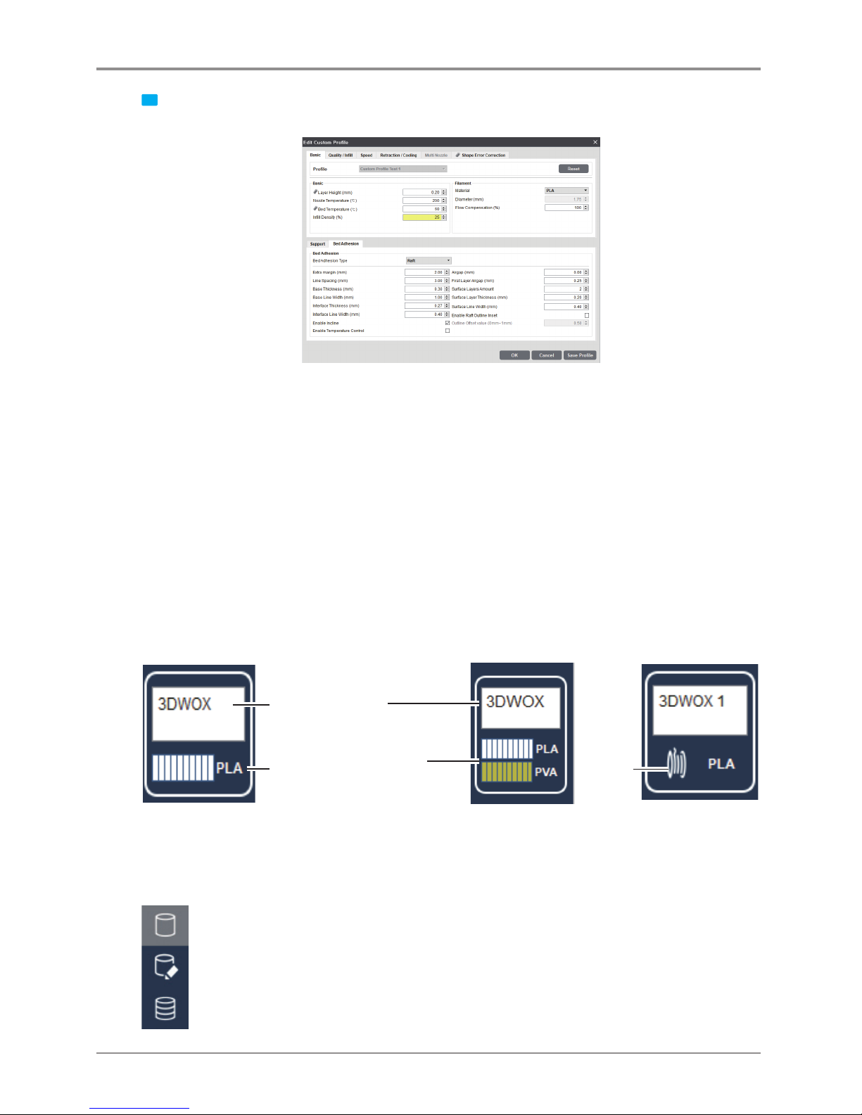
2 Clicking the [Edit] button → [Edit Custom Profile] window
- This window is for editing and saving existing profile values.
- Clicking the [Reset] button will reset the setting values before they are saved (before the “OK” or
“Apply” button is clicked).
- In the case of the 3DWOX 1, 2X/2X DP303 and 1X/1X DP302 1 model, the “Filament” and the
“Material” fields of the [Default Setting] will show the “ETC” profile.
The user should select the “ETC” material if he/she uses a material that is different from those
provided by Sindoh.
* [OK] button: This will save all the setting values and close the dialog box.
* [Cancel] button: This will close the dialog box without saving the setting values.
* [Save Profile] button: This will save the profile setting values without closing the window.
2.4 Filament Information Indicator
Printer automatically reads condition of filament in printer and displays on screen.
Detail description
Current default printer
name
In open
material
mode
Current quantity, condition
and remaining material
of filament inside the printer
<DP200/DP102, DP201/DP202,
3DWOX 1,1X/1X DP302 >
<2X/2X DP303 > <3DWOX 1,
2X/2X DP303,
1X/1X DP302>
2.5 View Mode Selection Button
At the top right hand side of the viewer, you will see buttons as shown on the left. Clicking the button
on the screen will display three types of view modes to be selected. (From the top, Normal View,
Support Edit View, Layer View ) Once selected, the selected view type is highlighted for the user.
Page 14
14
Detail description
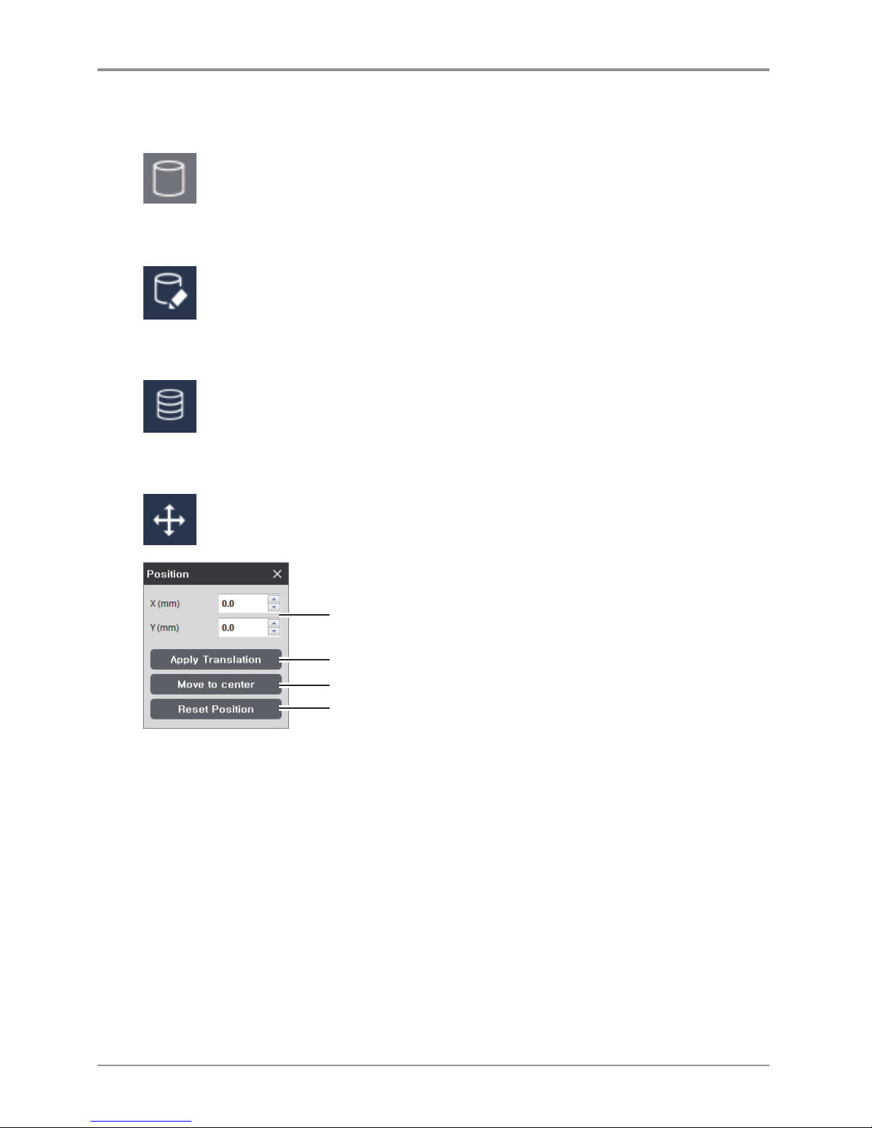
3D Model Viewer
This mode renders the 3D model loaded and displays it on the screen.
In this mode user is able to change position, angle and size of the 3D model and print it out.
Support Edit Viewer
When the model contains a slant surface, s support is needed at the bottom of the model to ensure
good printing output. Hence, in this mode user is given the accessible views to position the support
at the right location.
Layer Viewer
This mode slices the 3D model to print. Pressing this button allows user to slice 3d model parallel to
the printer bed by reflecting parameter values, and to display the layers.
2.6 Moving a model
Moves the model on screen in directions of x and y axes.
Moves (in mm) a selected model in two axes.
Applies values to model. (Equivalent to Enter key)
Place the selected model in the center of the bed.
Moves the selected model to the location where it was initially loaded.
Page 15
15
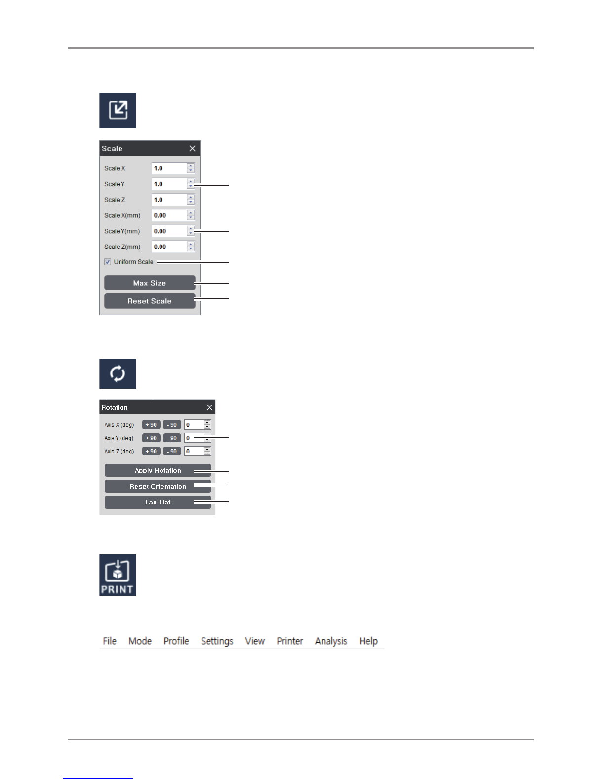
2.7 Adjusting Model Size
Scale and length of selected model on screen can be adjusted.
Size of scale can be controlled in direction of three axes.
Size of length can be controlled in direction of three axes.
Expansion and contraction on the x,y,z directions at the same ratio.
Adjust model to maximum printable size.
Reset to original size.
2.8 Model Rotation
Selected model can be rotated in the direction of the three axes.
Enter the angle to rotate in three axes.
Restore the model’s original direction when it was initially loaded.
Apply the entered value to the model (Same as the Enter Key)
IIf the model’s angle is tilted, this will automatically adjust the angle so that the
model is adhered to the flat surface of the bed.
2.9 Print
Connect to a printer to print a sliced model over the network
2.10 Standard Menu Bar
Contains File, Settings, and Network printer related functions and located at the top of the program window.
Page 16
16
2.11 Select a Cartridge
-
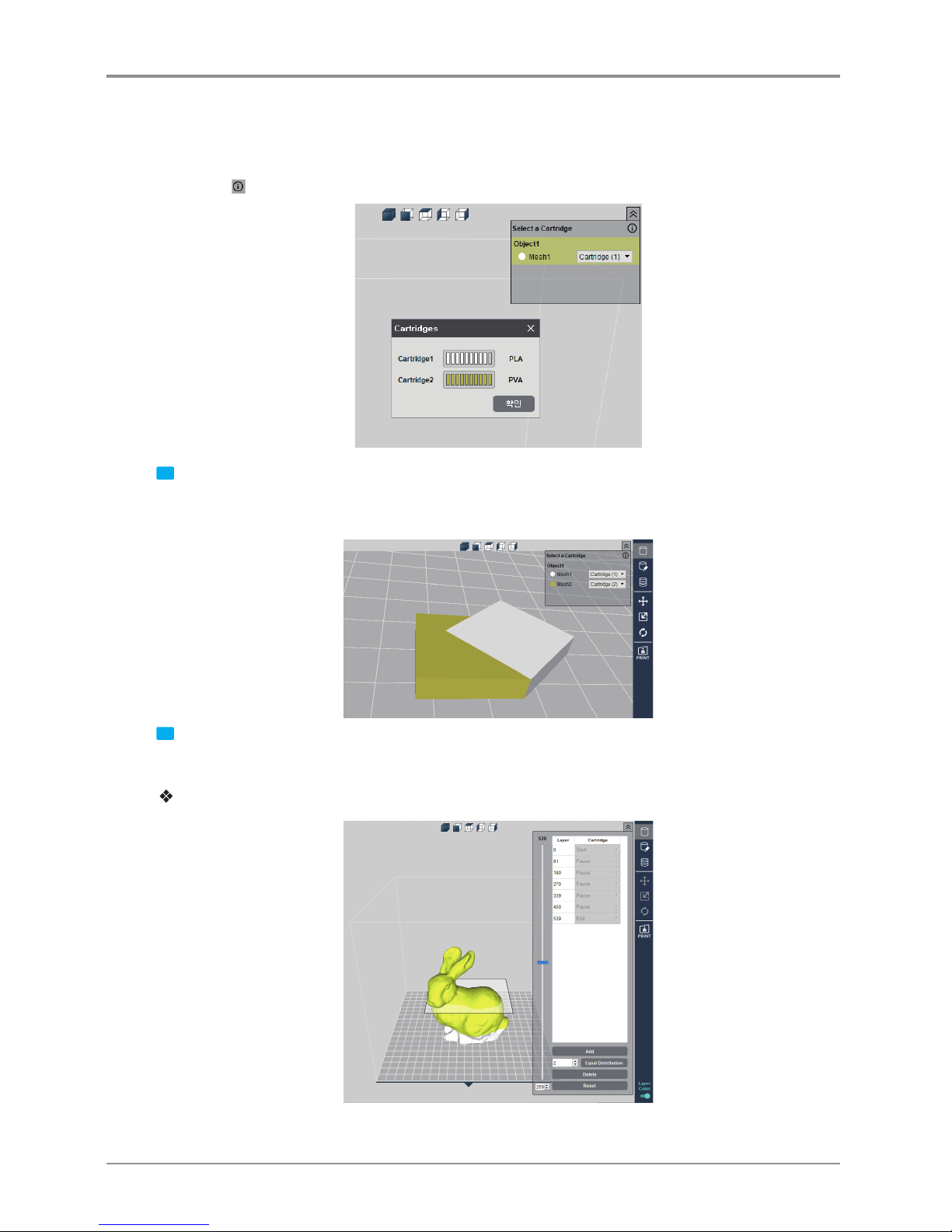
It is enabled only for the 2X or 2X DP303. When two models or a model consisting of two or more meshes
is loaded, it may print with a different cartridge by specifying the cartridge number for each mesh or object.
-
Press the button to check the filament amount of each cartridge.
1 When the Layer Color is off, [Select a Cartridge]
To print Mesh 1 with Cartridge 1 and Mesh 2 with Cartridge 2, select the cartridge for each Mesh as shown
above.
2 When the Layer Color is on, [Select a Cartridge]
If the Layer Color is activated, a 3D model cannot be right-clicked. (To delete or move object.)
For DP200/DP102, DP201/DP202, 3DWOX 1 and 1X/1X DP302
- Pause the printing on the desired layer. Unload the cartridge, replace it, and continue printing.
Page 17
17
For 2X and 2X DP303
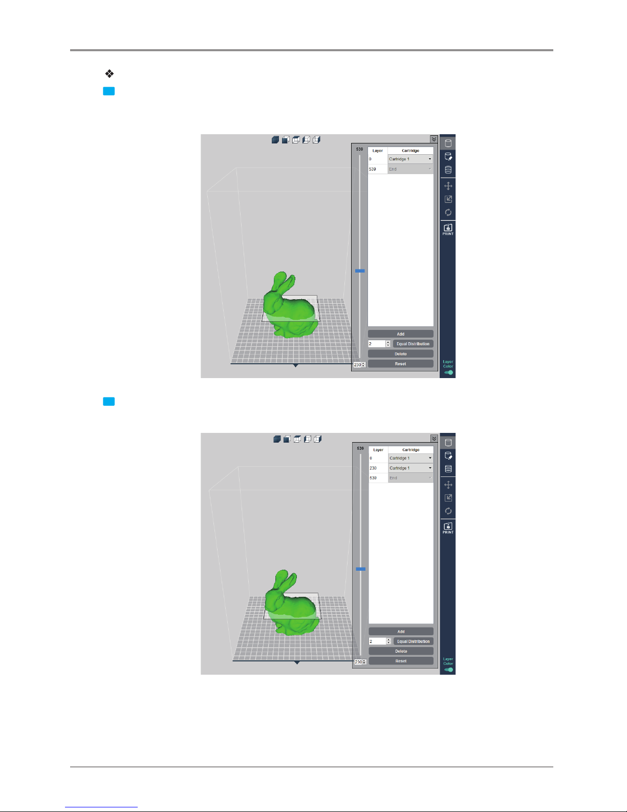
1 The Layer Color is a function to specify different cartridges for different layers. Move the left-side slider to
show slider positioned layer and the layer number. Position the slider at cartridge change desired layer
and press the [Add] button in the bottom.
2 Then, another tab is created to replace cartridges by layer. Move the slider, and press the [Add] button to
add more Layer Color.
▼
Page 18
18
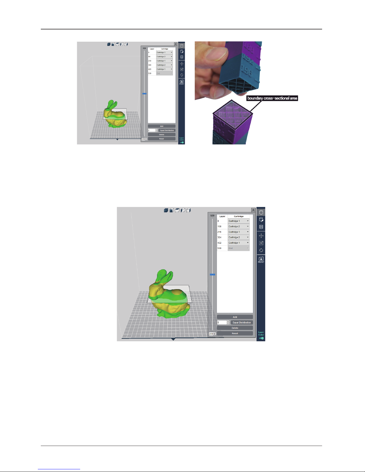
0th to 69th layers are printed by cartridge 1 and 69th to 230th layers are printed by cartridge 2.
If the boundary cross-sectional area of the layer color is small, increase the infill density of the internal
filament for ensuring durability.
2.12 Equal Distribution
Enter desired number of layers, and press the [Equal Distribution] button to divide all layers evenly.
Page 19
19
2.13 Merge & Split
It is not applicable if the [Layer Color] is enabled.
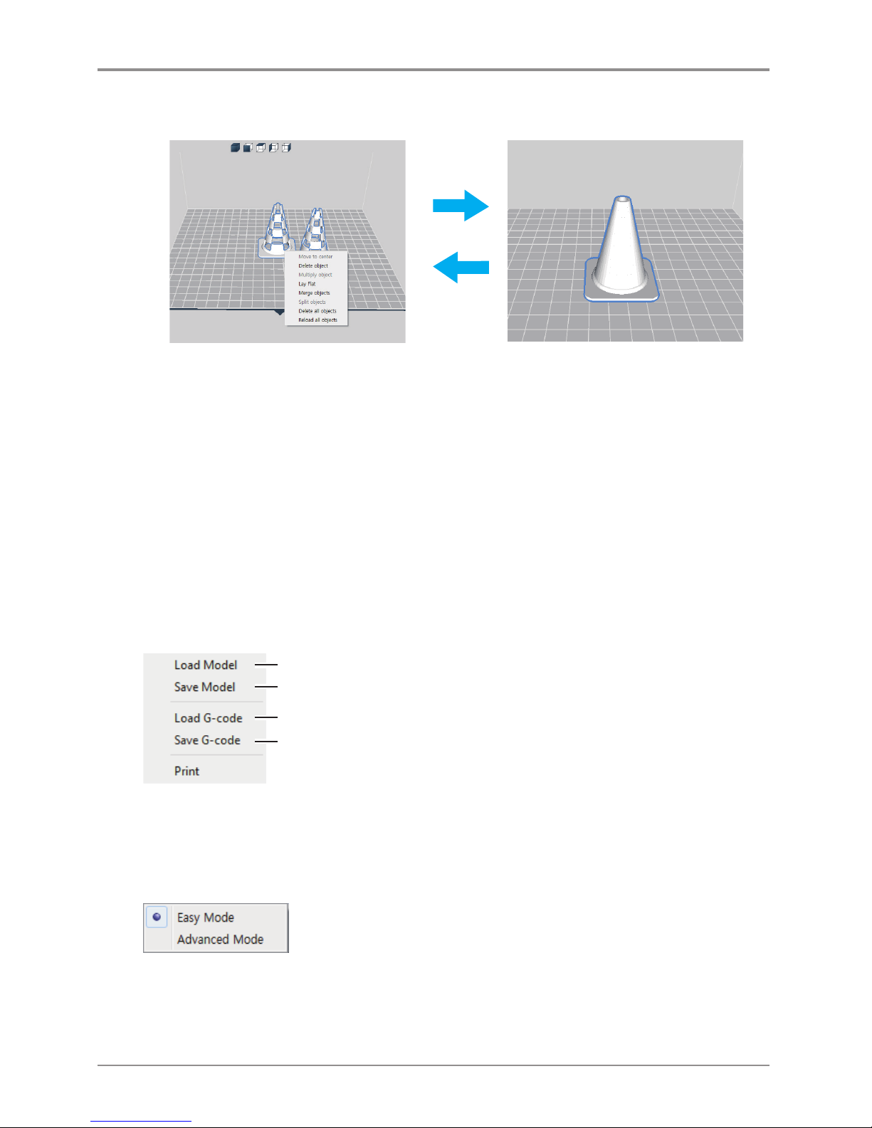
Merge
Merge is a function to align the axis with respect to the origin.
Ctrl + Select (left-click) two or more objects. Then, right-click and click merge object to merge the selected
objects. After merging them, it can be checked with Select a Cartridge. Individual meshes can be assigned to
different cartridges.
Split
Right-click and click Split to split the merged object.
Detail description
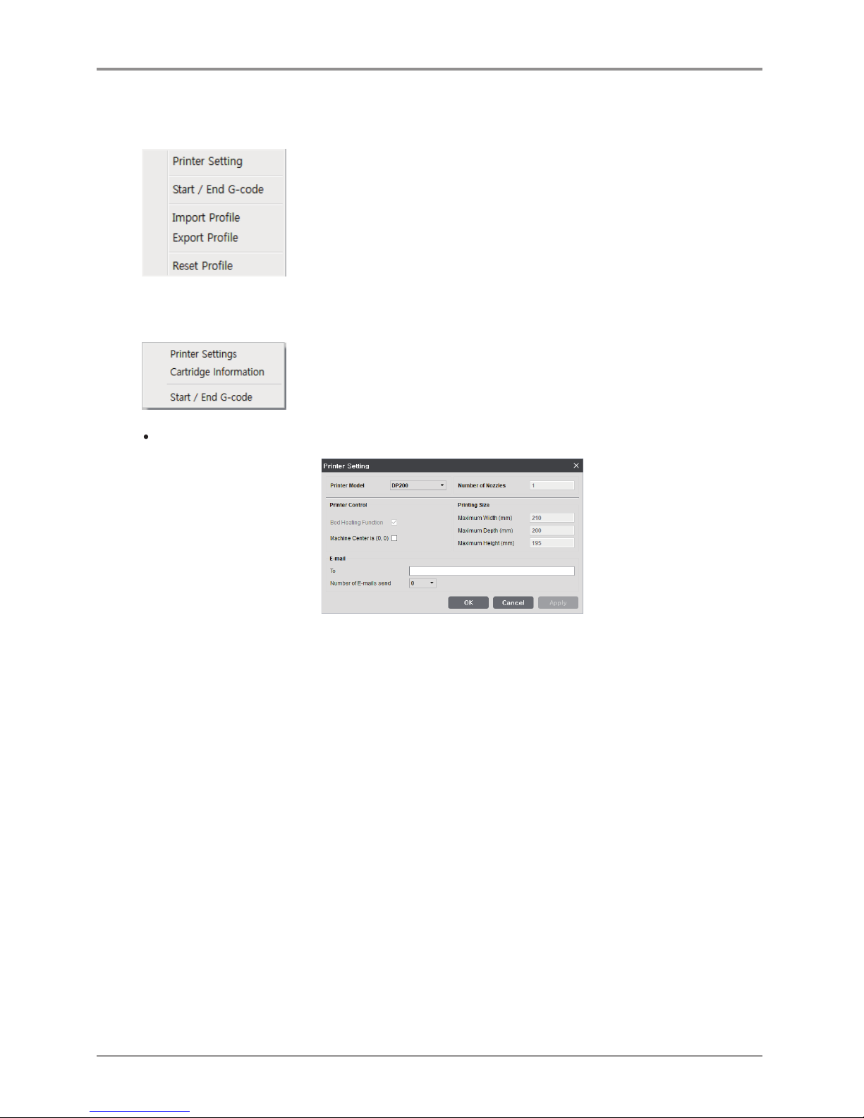
File
Loads 3D model (equivalent to Load button)
Load G-code and the model to show the print path
Save the loaded model to another type of file or name
Save G-code after slicing the loaded model
MODE
3DWOX offers users two types of different modes for slicing.
“EASY MODE” offers a predefined setting for a fast and easy print, “ADVANCED MODE” allows users to
set each and every detailed value for user preference, to achieve desired printouts.
Page 20
20
Profile
There are many profile-related functions. For custom profiles, see “2.3 Custom Profile.”
Setting
This enables the designation of various setting values needed for slicing.
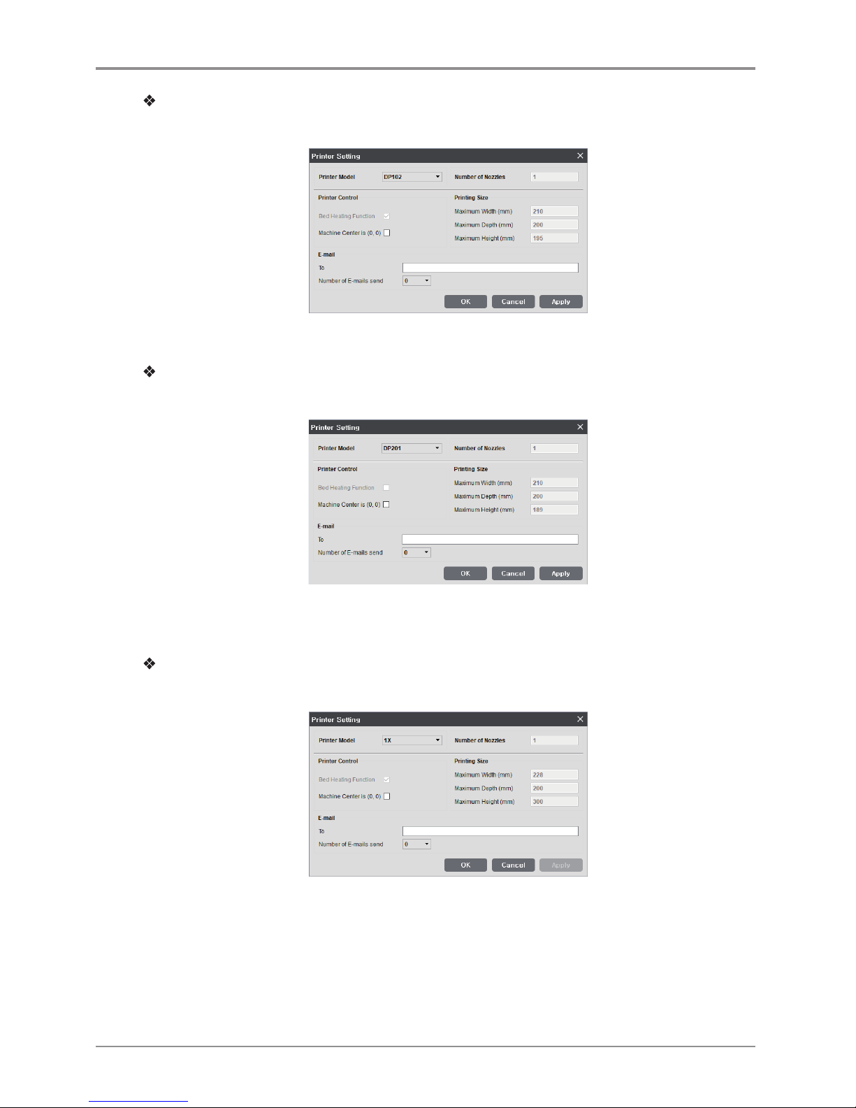
Printer Setting (DP200/DP102, 3DWOX 1)
- Printer Model: A connected default printer appears on the screen.
-
Number of Nozzles: The number of nozzles of the device is displayed
-
Bed Heating Function: Only select when bed heating function is available. When left unchecked, G-code
for bed heating will not be created.
-
Slicing Origin Point Correction (based on the equipment’s origin point): Place the 3D model on the
bed based on the equipment’s origin point (0,0).
-
Origin Correction (Bed center): Automatically controls model to be always positioned in center of printer
bed.
-
Maximum Printing Size: Insert maximum printable size of the connected printer.
-
E-mail: Sends the printing status to the entered e-mail address.
Under “email,” input the recipient email address(es) and select the number of times to send the
notification emails. Additional recipient addresses can be added by using “;.”
The maximum number of notification emails that can be sent is 10.
An email notification, an email will be sent out for the user to see if the email notification is working properly
by default. So the email will be sent out one more time than the number that the user entered. However,
the number of email that is sent will not exceed 10 times.
(When user selects 10 times, the notification email will be sent out 10 times)
Page 21
21
When the printer in use is
DP200/DP102, 3DWOX 1
- Below is the settings screen of DP102.
- Printer Settings screen and features are same as DP200 and 3DWOX 1.
When the printer in use is DP201/DP202
- For DP201, the printer setting screen has been changed as below.
- Bed Heating Function: This function is deactivated for DP201/DP202.
Beside the change above, other setting screens are same as DP200/DP102.
When the printer in use is 1X/1X DP302
- For 1X, the printer setting screen has been changed as below.
- Printer Settings screen and features are same as 1X DP302 and DP200/DP102.
Page 22
22
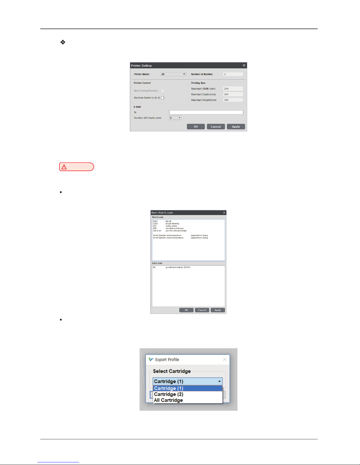
When the printer in use is
2X/2X DP303
- For 2X, the printer setting screen has been changed as below.
- 2X/2X DP303 has two nozzles.
Beside the change above, other setting screens are same as DP200/DP102.
Caution
- E-mail feature must be selected from the UI menu before being used.
For further details, please refer to “UI Menu Feature Description.”
Start/End G-code
View default settings for start/end code, modify text to apply to sliced model.
Import/Export Profile
This function allows user to import predefined profile parameter values or export values for slicing.
File format for profile is *.ini and editing is available through “notepad”.
2X performs Import/Export by cartridge.
Page 23
23
Reset Profile
Resets all profile parameter values to default value.
View
Able to choose viewing mode that is equivalent to features of View Mode Selection button. For more
details, please refer to “2.4 View Mode Selection button” on page.11.
Printer
Finds and adds printers on the network.
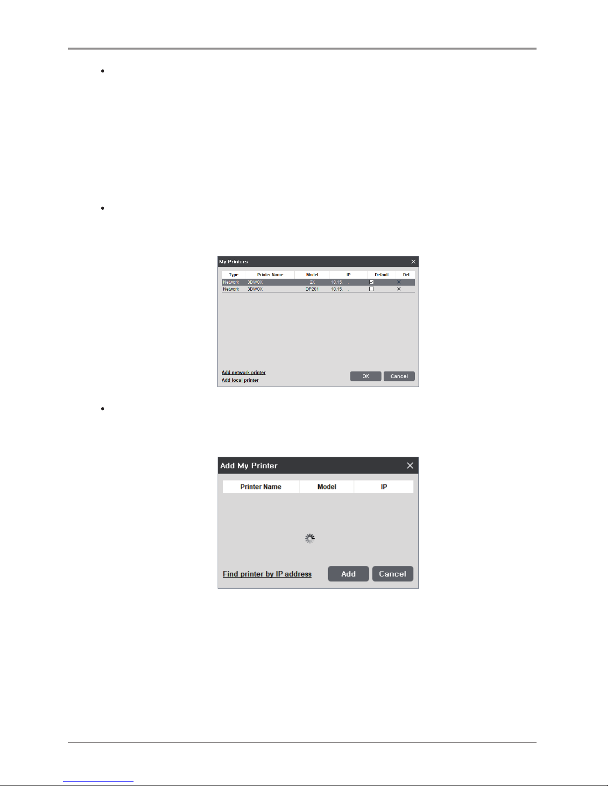
My Printer Management
This screen manages the printers added by user.
On restart of the program, without any settings required, prints will be directed to the default printer.
Add Network Printer
Automatically searches and finds available printers in network.
Select from the found printers and press “add”, then selected printer will be added to “My Printer”.
Page 24
24
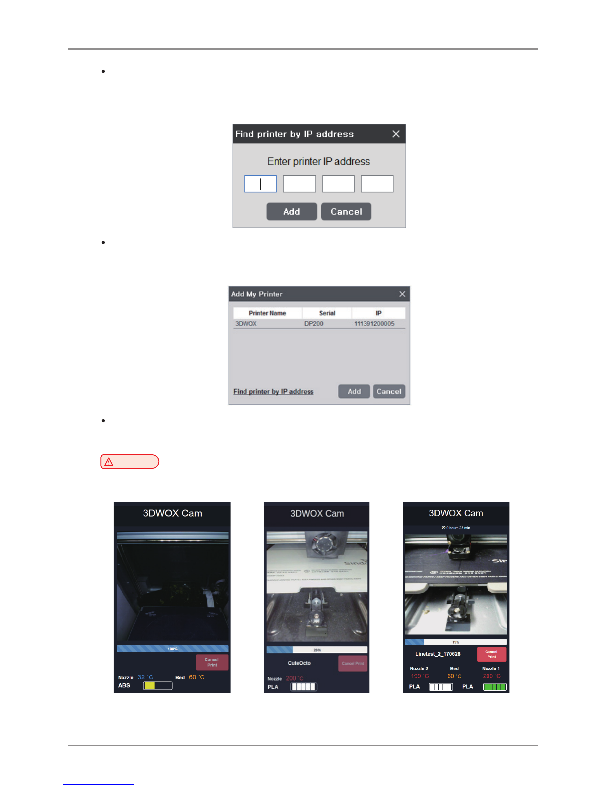
Find Printer by IP Address
Add by inserting specific printer IP address.
After typing the IP address, press “Add”. if the IP address is available, the printer within the IP address will be
added to “My Printer”.
Add Local Printer
Automatically searches the printer that is connected by the USB Cable and displays it on the screen.
If you click the [Add] button after selecting the searched printer, the printer is added to “My Printer”.
Web Monitoring
Function allows user to monitor the operation of the network printer connected to this program.
Caution
- Compatible browser versions are Internet Explorer 11 or FireFox 40.0 or Chrome 47.0 or higher.
Some features may not function properly if the browser version is lower than the above.
< DP200/DP102, 3DWOX 1and < DP201/DP202 > < 2X/2X DP303 >
1X/1X DP302 >
Page 25

25
Analysis
This function analyzes the 3D model and notifies user of any problems that might arise.
(refer to Advanced Functions)
Help
User can gain access to information on Language, Keyboard Shortcuts, Online FAQ and Program Updates.
Page 26
26
3. Printing (basic functions)
Explanation of the steps to printing 3D model using base functions.
3.1 Loading 3D Model Files
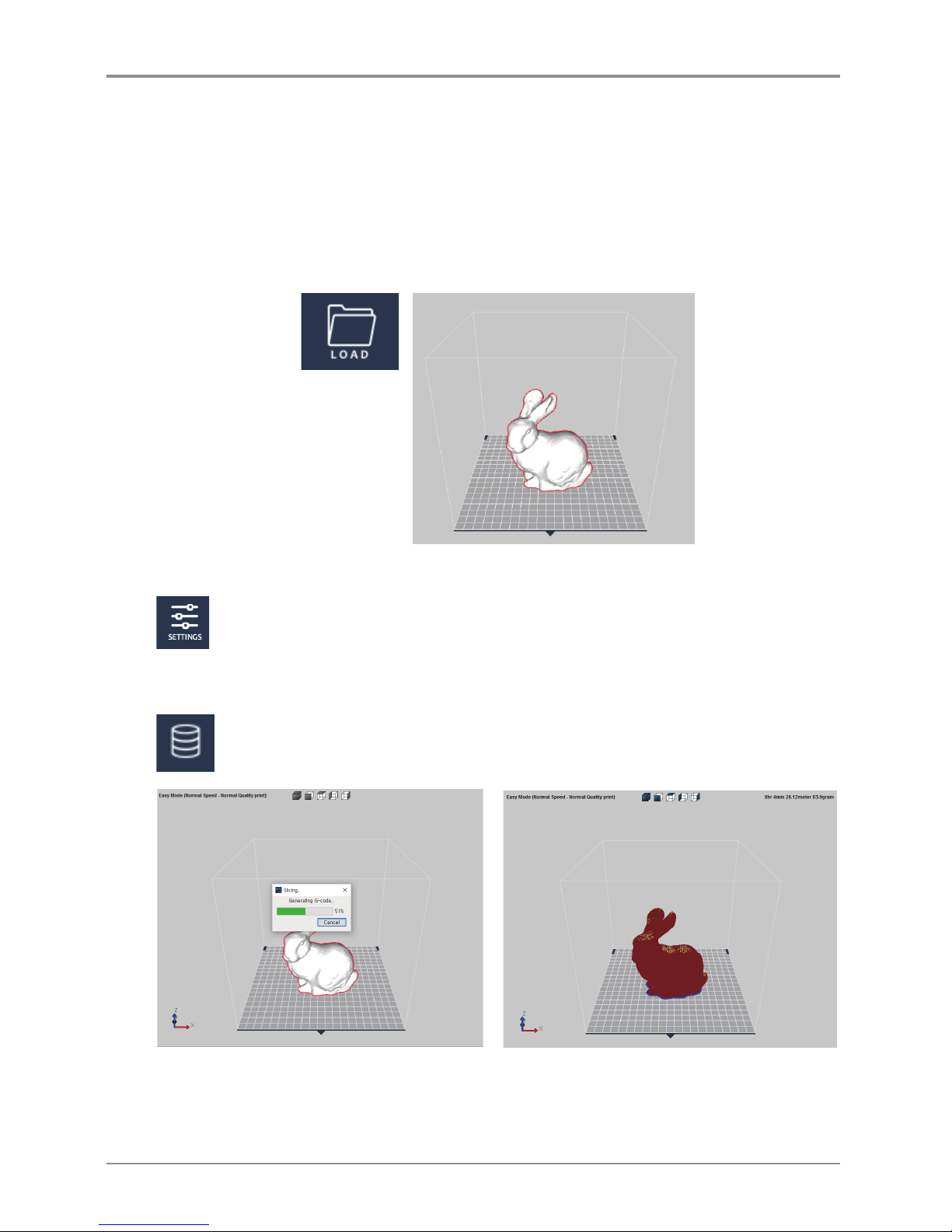
Click on the [LOAD] button located on the left hand side of the screen and select the 3D model file user wants
to import. (For each function refer to detailed descriptions).
Selected model will be positioned in the center of showing printer bed.
3.2 Basic Parameter Setting
Click on the [SETTING] button to change any parameter values.
e.g.) change the slicing layer height value which does determine the quality of the printable or
adjust the support application.
3.3 Slicing
After checking 3D model is positioned on the bed, selecting Layer Viewer mode will apply the
parameter values and execute the slicing.
The result of slicing in the layer view will be displayed on screen.
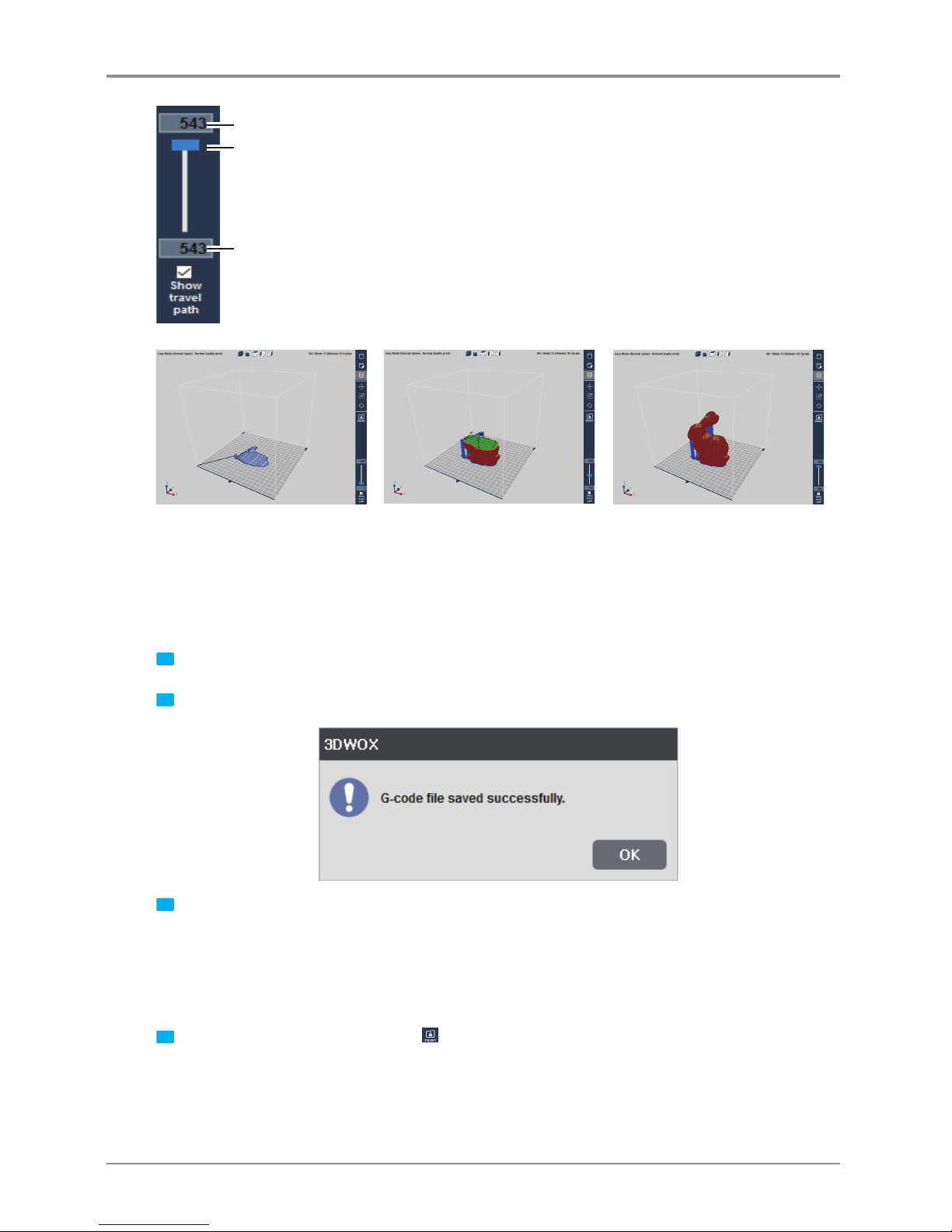
Model will not be a whole instead will be displayed in lines of layers, using the slider located at the bottom,
user is able to analyze each layer of the model.
Page 27
27
Slider to move to the desired layer
Current layer on screen
Total layer number
3.4 Print
There are three ways to print the sliced model.
USB Thumbdrive
1 Slice the model and press [Save G-code] on the File menu.
2 Save the G-code file in the USB Thumbdrive.
3 Connect to the USB port on the front side of the printer and load the G-code file to directly print the model.
Network Connection
In order to use this function, the printer has to be connected through network.
More details can be found in the <My Printers> and <Add Network Printers> section.
1 Slice the model and select the print Icon
on the right or
[Print]
in the File menu.
Page 28
28
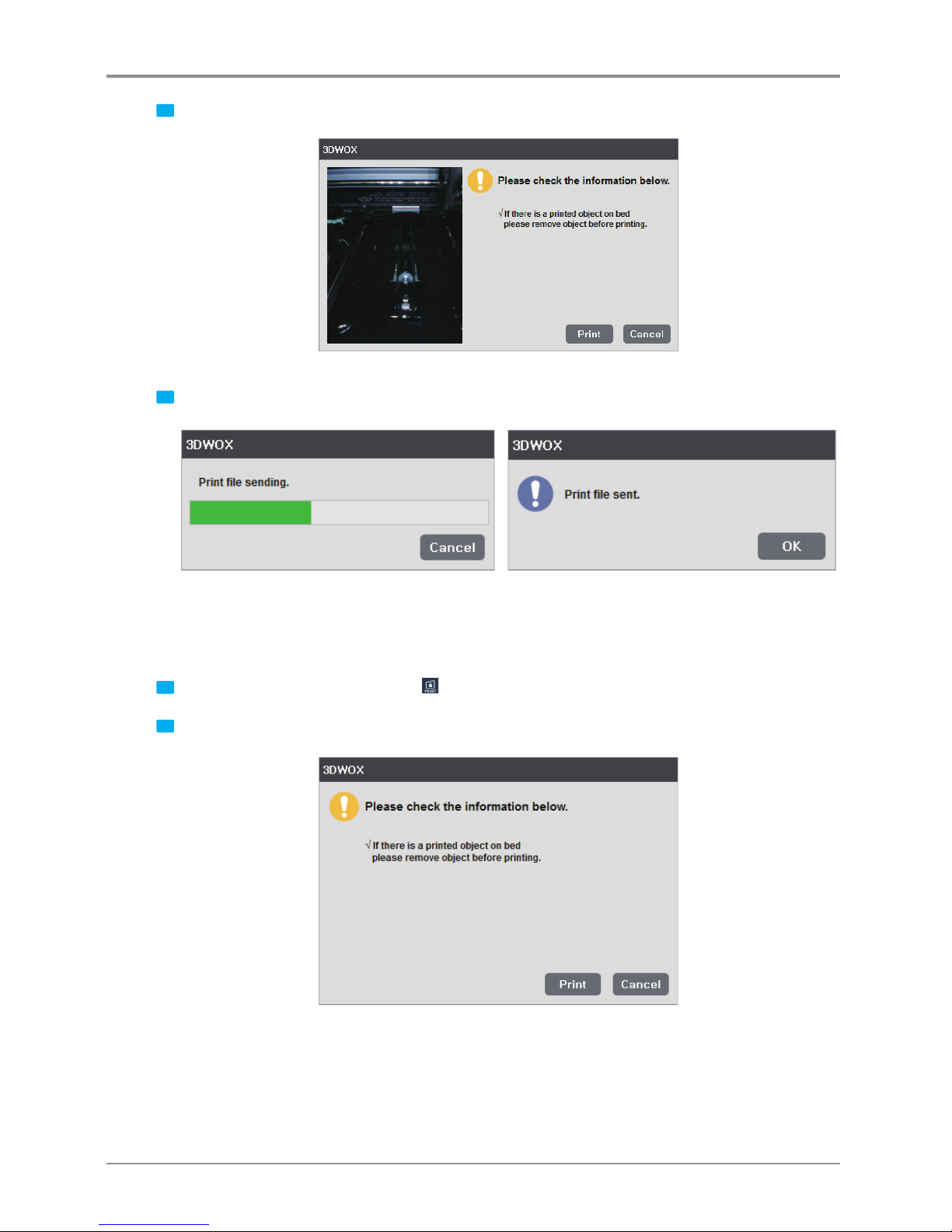
2 If the monitor shows no problems as shown below, press [Print] to begin printing.
3 G-code is sent through the Network and the printer begins printing.
Local Network Usage
In order to use this function, the printer must be connected through the USB cable.
More details can be found in the <My Printers> and <Add Local Printers> section.
1 Slice the model and select the print Icon
on the right or
[Print]
in the File menu.
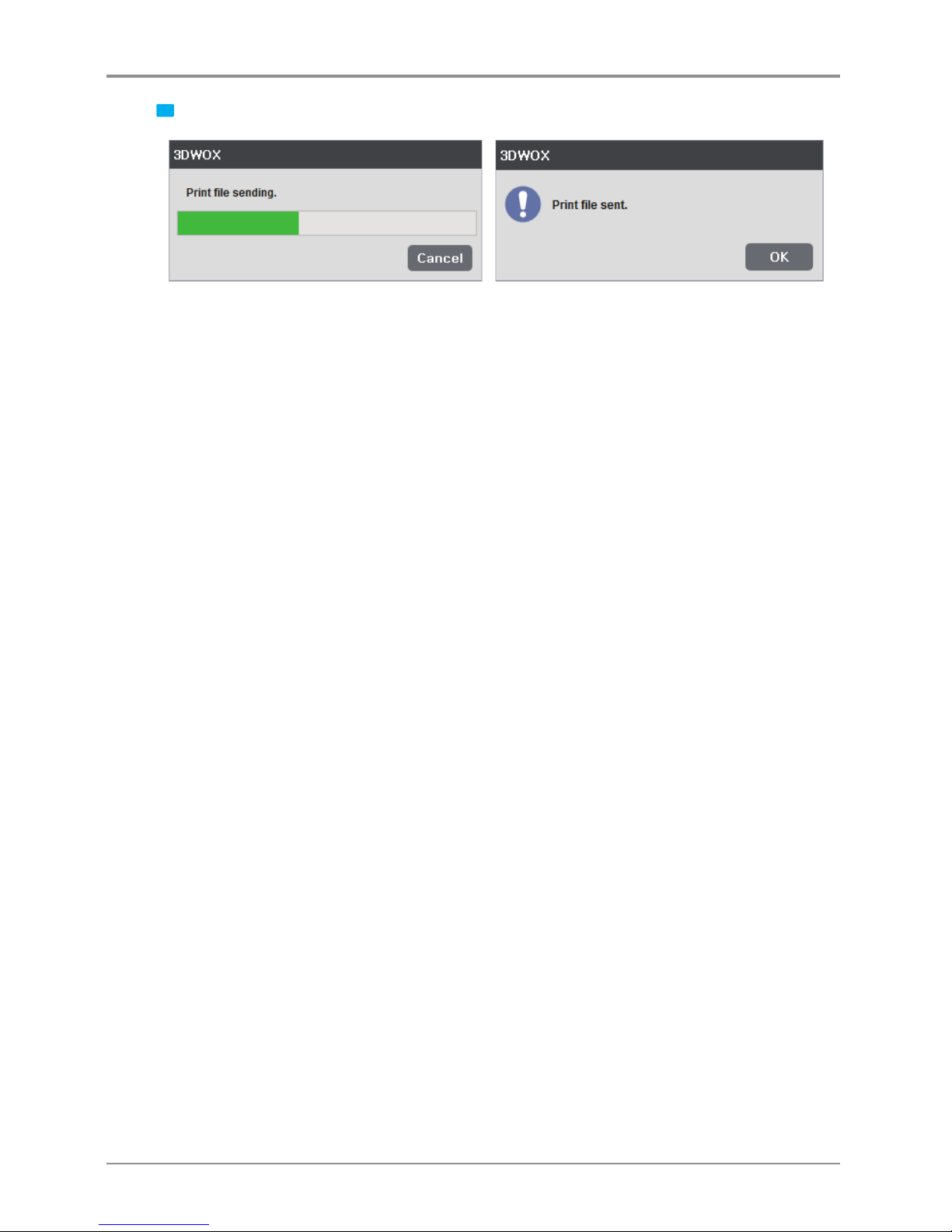
2 If the monitor shows no problems as shown below, press [Print] to begin printing.
Page 29
29
3 G-code is sent through the USB Cable and the printer begins printing.
Page 30
30
4. Advanced Features
4.1 Support Edit Function
3DWOX offers users to not only use the setting values automatically calculated by the program but can be
changed manually.
Thus, you can add or delete additional supports in addition to the established supports.
These types of editing tools can be executed in Support Editing View Mode.
Support Editing View Mode
3D Model
First load 3d model into program.
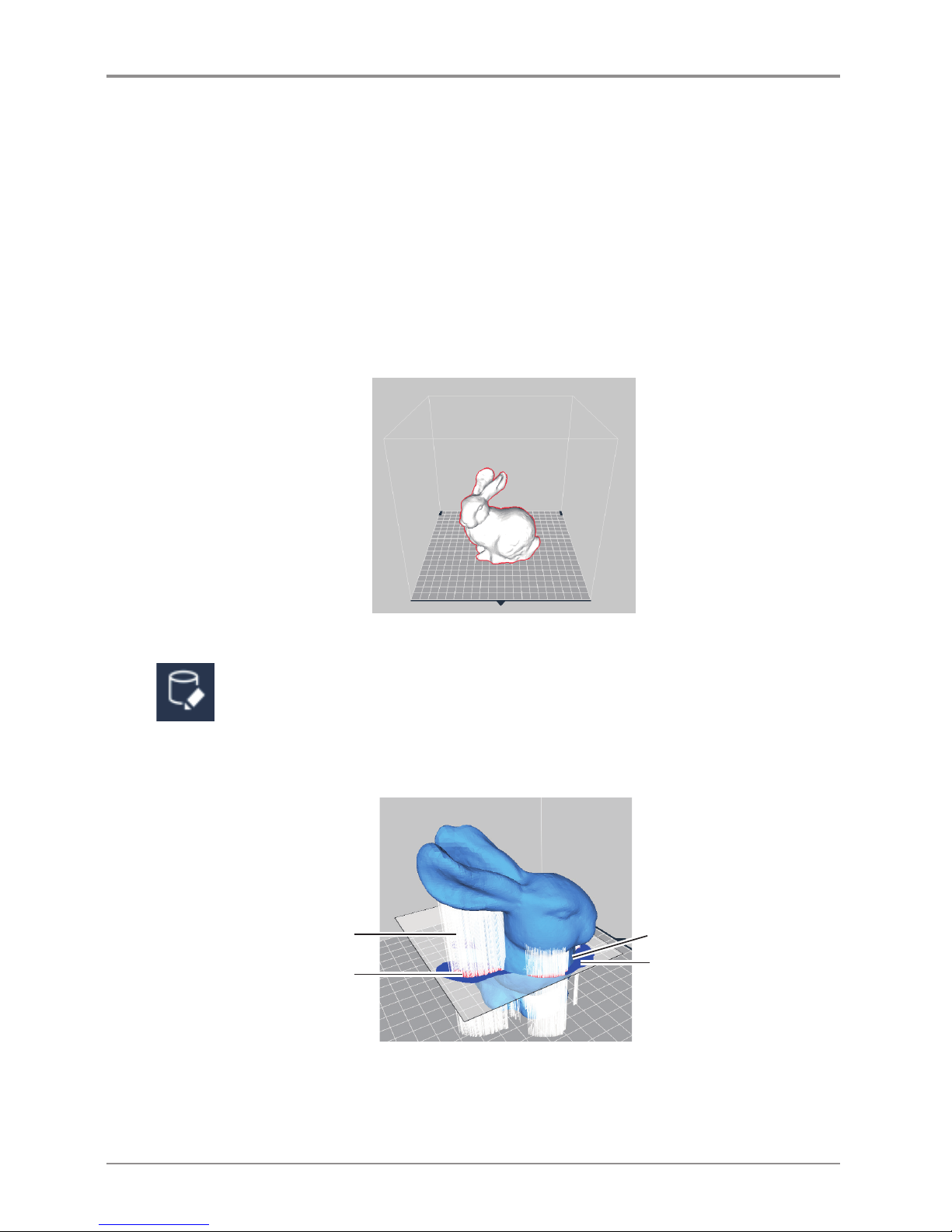
Conversion to Support Edit Viewer mode
Click Support Edit Viewer mode button located on right side of screen.
By changing View mode user will be able to view model with supports, shown below.
Brief explanation of support edit view is as the following.
Support edit section
Inactive field (Blue)
Section of field which
support is not created
Support to be created
Active field (Red)
Section of field where
perpendicular support
will be created.
By standards support is shaped in a section projecting in the direction of Z axis.
Thus, shape can be created in perpendicular direction and support edit cross sections will show the maxi
mum area that support can be created in the current section.
Page 31
31
Creating and Removing Support
Support Creation
To create a support, click on the inactive area (blue) in the edit region.
Now, the region will turn red and creation of perpendicular supports can be seen .
Removing Support
To remove support, press and hold Ctrl key and click on the active area of the edit cross section.
The area that has been selected will turn black (inactive), Supports that have been created will be removed.
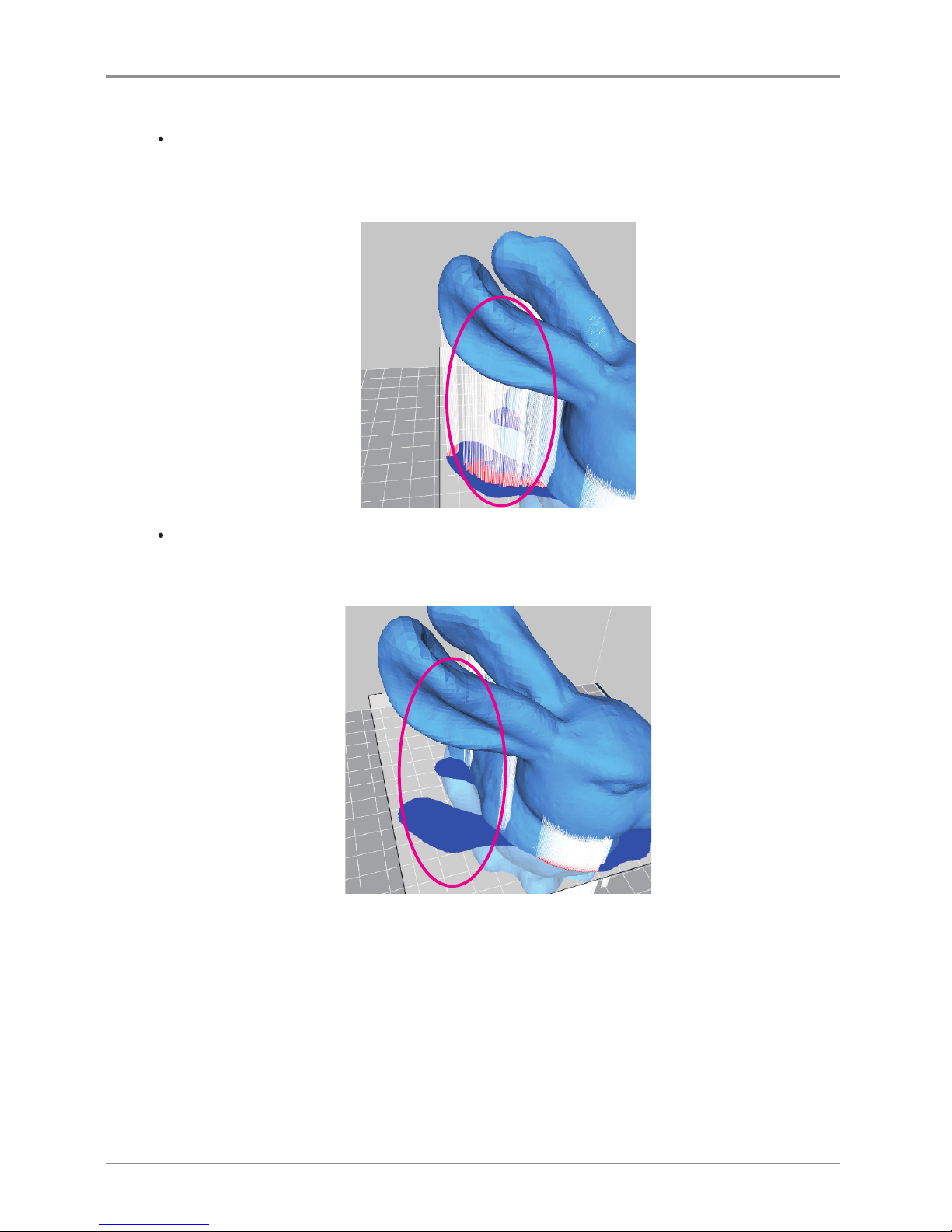
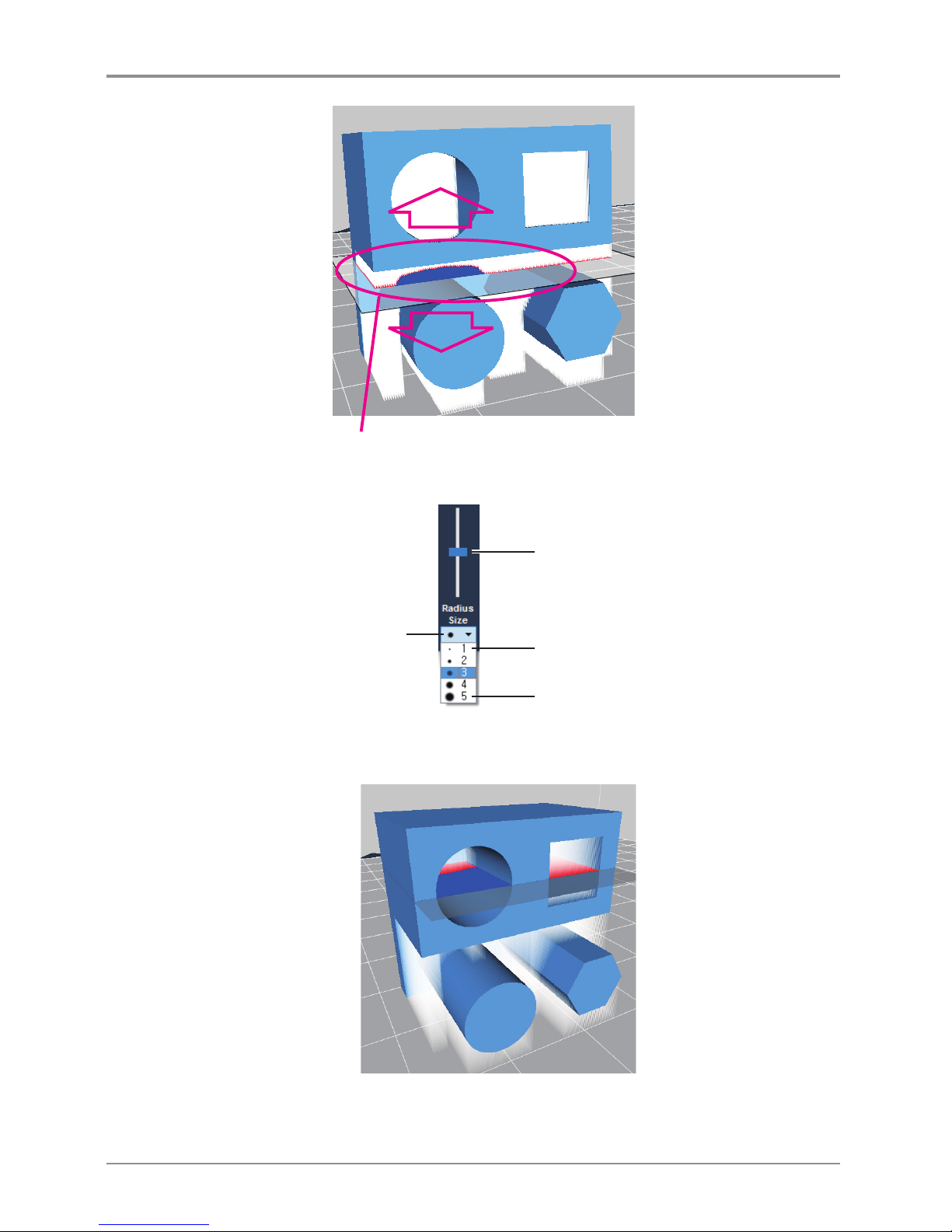
Support Edit Cross Section Maneuvering
Length of Support is determined by having the cross section as the center and creating a support vertically
both ways until a shape is created.
Thus, if there is a shape in the middle of the area, support creation have to be divided and edited separately.
For example like the model below, when editing the support located in the middle of the model, in the circle,
only the lower half will be edited. So when removing, only the lower half of the support will be
removed, and the support in the middle of the model will remain as is.
Page 32
32
Because of the shape in the middle, Support area has been divided.
Minimum size of editing
Maximum size of editing
Current Support editing size
Support Edit Maneuvering Slider
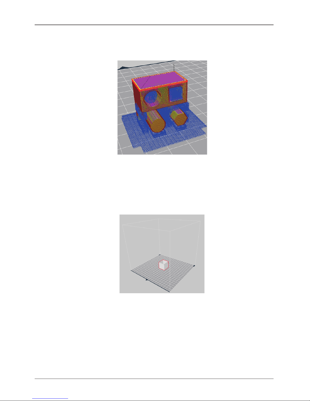
To edit the support inside, the model user has to move the edit cross section.
Use the support edit slider to maneuver around.
Move the Support Editing Cross Section up to place it in the area to edit.
The supports of the interior can be edited by clicking on the interior area of the editing cross-section.
Page 33
33
Creating Final Support
After finishing the touches to the support, change to Layer Viewer mode. The model will go through the
slicing process again. Now the user can interact with the finished slice with edited supports.
4.2 3D Model Analysis Function
3DWOX has the function where printing the program analyses the shape of the 3D model and informs
user of any problems that might occur before printing. Performs thickness analysis of the model based on the
cross section of the slicing direction and analyses the counter gradient of the shape in the z axis direction.
Select 3D Model
Click and select the 3D model.
Page 34
34
Under Analysis menu, select Thickness / Overhang.
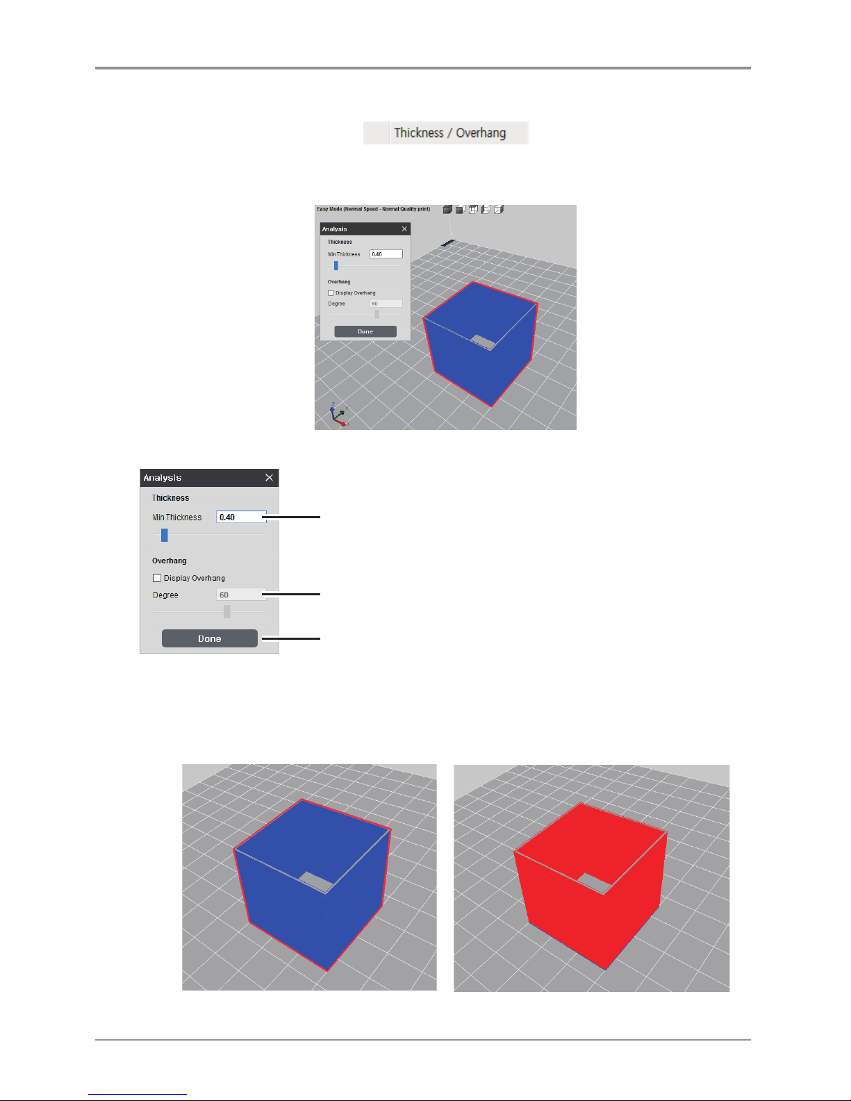
At the top of the screen, under the Analysis menu select Thickness / Overhang. The analysing process is
displayed and calculated results and analysis control window appears.
Analysis Control Window
Controls the thickness.
Display Overhang function on/off.
Controls the angle of Overhang.
Thickness Analysis Function
Shows layers that are thinner than the minimum thickness value. If minimum thickness layer was set to
0.4mm, any layers that are thinner than 0.4mm (in the order of BLUE and RED) will be indicated,
and user will be notified with any problems that might arise.
<Geometry is thicker than set value> <Geometry is thinner than set value>
Page 35
35
Overhang Analysis Function
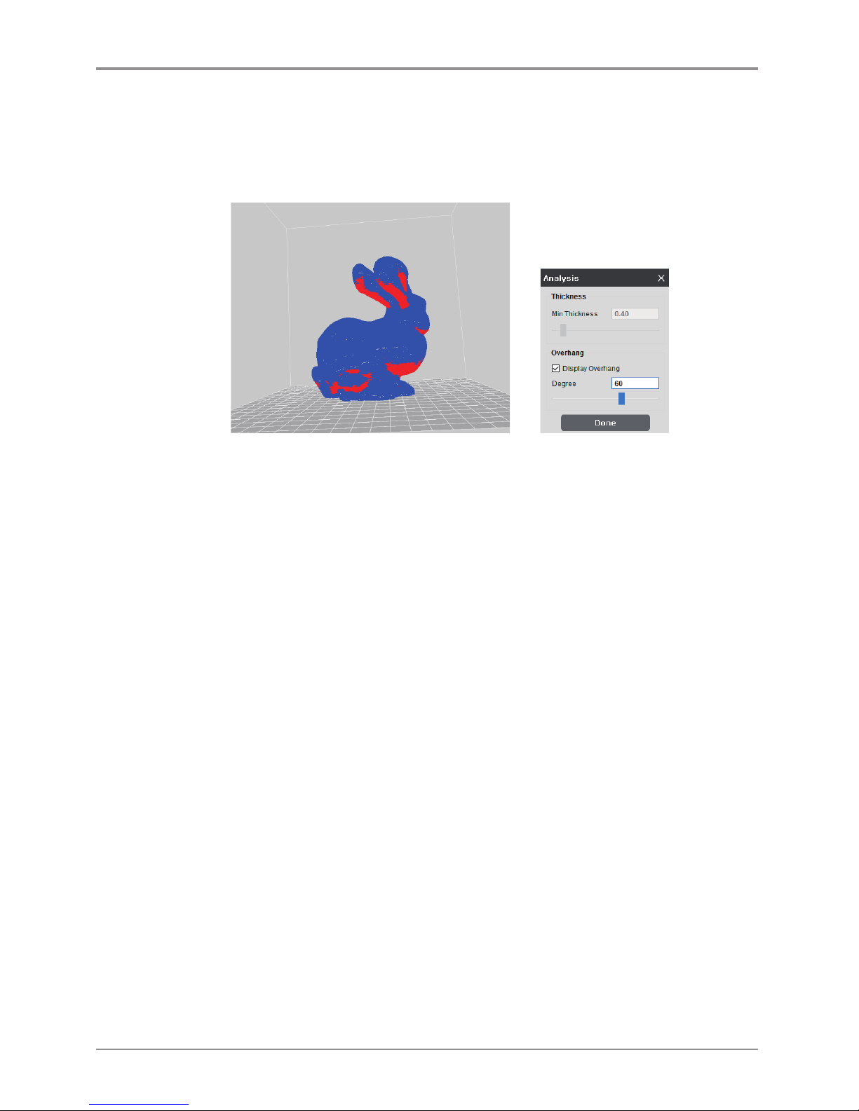
In 3D printing, it’s very favorable if object is perpendicular to bed surface, more horizontal the shape is,
the more disadvantageous it is. When the angle in horizontal direction is small, supports are needed.
The Overhang analysis function calculates the geometry’s inverse draft and notifies the user of possible
problems that might occur during an actual printing.
4.3 Function to Calculate Optimal Printing Direction
3DWOX has a feature which caculates and recommends the user the most optimal direction for printing.
On the basis of pre set standards,this feature caculates 6 different printing directions having the Bed as the
base and shows the optimal direction to the user. There are 3 types of evaluation criteria and explanation
for each type is as follows.
Estimated Printing Error Surface
Using thickness analysis of the 3D model, the function calculates the area of the part thinner than the
current nozzle diameter. For areas which are thinner than the nozzle diameter, there is an extensive chance
that the model may not accumulate as expected. So the program pre-calculates these to find printing errors.
Overhang Surface
Through Overhang analysis, the program takes into consideration of errors that might occur during printing.
Smaller the Overhang surface is, better the quality is. Thus, considering the calculated area value in the
opposite way, the optimal printing direction is determined.
Amount of Support
Where there is an Overhang, support is needed for a normal accumulation. However, more supports
there are, lower the quality and longer the printing duration becomes.
Taking the factors into consideration the program pre-calculates the optimal printing direction.
Page 36
36
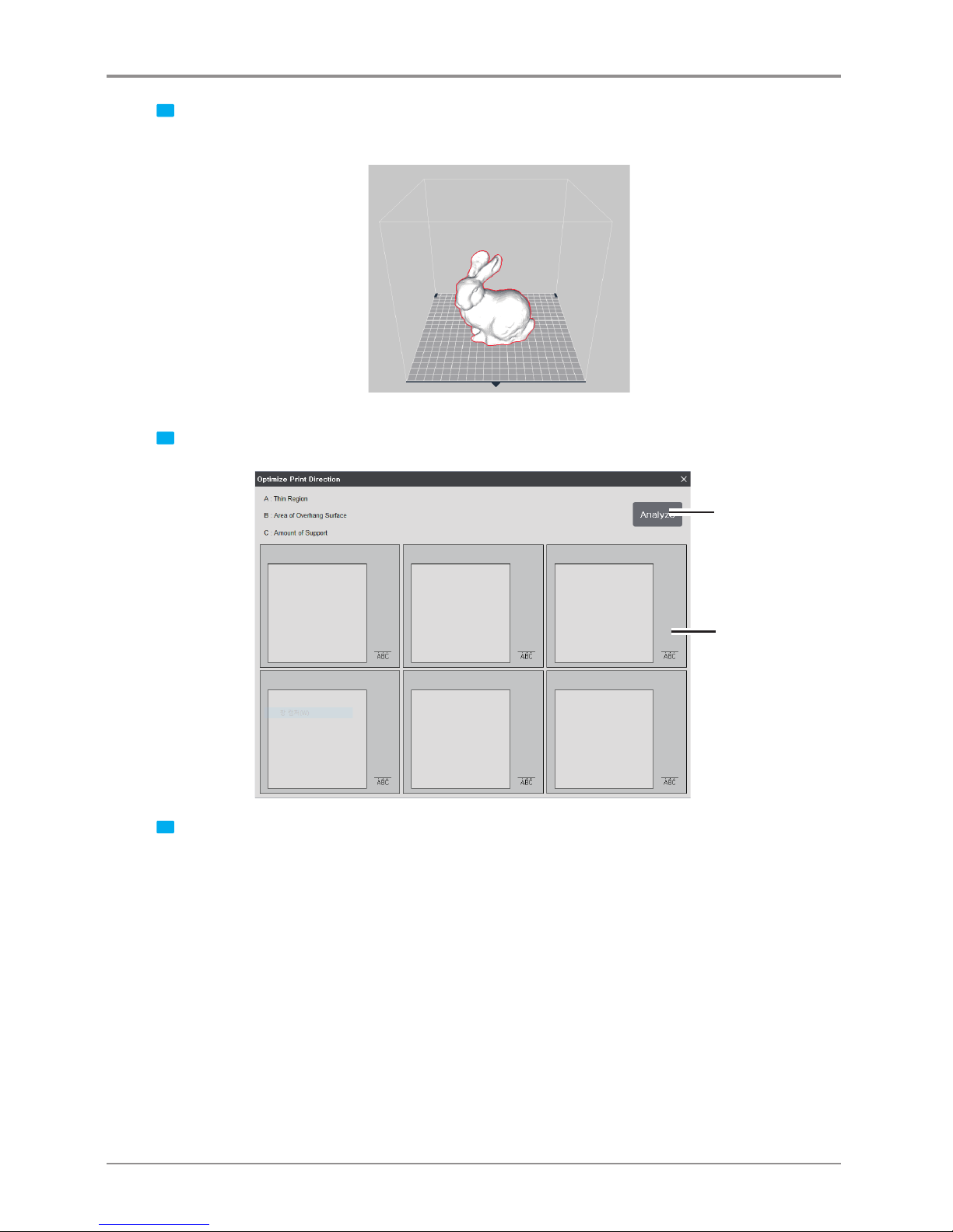
1 Select 3D model
With the 3D model loaded, click on the model to select.
2 In Analysis menu, select “Optimal Printing Direction” and a window similar to the following appears.
Calculate
Graph
for each
evaluation
criteria
3 Calculation for each 6 different direction would be initiated once the user clicks on the Caculate button.
Page 37
37
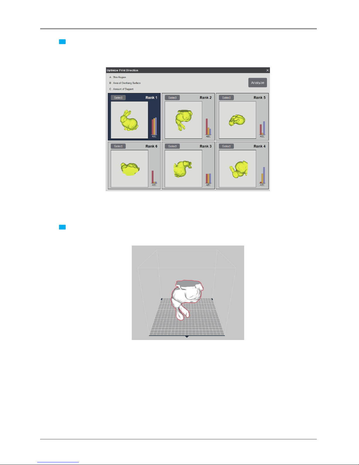
4 Results of 6 different directions of the model will be displayed, and each direction will be ranked on the
evaluation results. Following the results of the evaluation, the most optimal direction will be graded
accordingly,and a graph of each evaluation analysis can be examined.
The taller the graph, the higher the scores are achieved for the corresponding evaluation criteria.
All scores would be added and ranks of the 6 directions be displayed on the screen.
5 Select the preferred direction by pressing the “select” button, and the model appears facing the direction
selected. (Rank 2 had been selected in this reference image image)
Page 38

 Loading...