


USER'S MANUAL
ELEMENT 2 SERIES indoor unit
ASH-09AIE2, ASH-12AIE2 ASH-18AIE2, ASH-24AIE2
„Original instruction“

Precautions
 WARNING
Operation and Maintenance
 This appliance can be used by children aged from 8 years and above and persons with reduced physical, sensory or mental capabilities or lack of experience and knowledge if they have been given supervision or instruction concerning use of the appliance in a safe way and understand the hazards involved.
 Children shall not play with the appliance.
 Cleaning and user maintenance shall not be made by children without supervision.
 Do not connect air conditioner to multi-purpose socket. Otherwise, it may cause fire hazard.
 Do disconnect power supply when cleaning air conditioner. Otherwise, it may cause electric shock. .
 If the supply cord is damaged, it must be replaced by the manufacturer, its service agent or similarly qualified persons in order to avoid a hazard.
 Do not wash the air conditioner with water to avoid electric shock.
 Do not spray water on indoor unit. It may cause electric shock or malfunction.
 After removing the filter, do not touch fins to avoid injury.
 Do not use fire or hair dryer to dry the filter to avoid deformation or fire hazard.
1
Precautions
 WARNING
 Maintenance must be performed by qualified
professionals. Otherwise, it may cause personal injury or damage.
 Do not repair air conditioner by yourself. It may cause electric shock or damage. Please contact dealer when
you need to repair air conditioner.
 Do not extend fingers or objects into air inlet or air outlet. It may cause personal injury or damage.
 Do not block air outlet or air inlet. It may cause malfunction.
 Do not spill water on the remote controller, otherwise the remote controller may be broken.
 When below phenomenon occurs, please turn off air conditioner and disconnect power immediately, and then contact the dealer or qualified professionals for service.
●Power cord is overheating or damaged.
●There’s abnormal sound during operation.
●Circuit break trips off frequently.
●Air conditioner gives off burning smell.
●Indoor unit is leaking.
 If the air conditioner operates under abnormal conditions, it may cause malfunction, electric shock or fire hazard.
 When turning on or turning off the unit by emergency operation switch, please press this switch with an insulating object other than metal.
 Do not step on top panel of outdoor unit, or put heavy objects. It may cause damage or personal injury.
2
Precautions
 WARNING
Attachment
 Installation must be performed by qualified professionals. Otherwise, it may cause personal injury or damage.
 Must follow the electric safety regulations when installing the unit.
 According to the local safety regulations, use qualified power supply circuit and circuit break.
 Do install the circuit break. If not, it may cause malfunction.
 An all-pole disconnection switch having a contact separation
of at least 3mm in all poles should be connected in fixed wiring.
 Including an circuit break with suitable capacity, please note the following table.Air switch should be included
magnet buckle and heating buckle function, it can protect the circuit-short and overload.
 Air Conditioner should be properly grounded. Incorrect grounding may cause electric shock.
 Don't use unqualified power cord.
 Make sure the power supply matches with the requirement of air conditioner.Unstable power supply or incorrect wiring or malfunction. Please install proper power supply cables before using the air conditioner.
 Properly connect the live wire, neutral wire and grounding wire of power socket.
 Be sure to cut off the power supply before proceeding any work related to electricity and safety.
3
Precautions
 WARNING
 Do not put through the power before finishing installation.
 If the supply cord is damaged, it must be replaced by the manufacturer, its service agent or similarly qualified persons in order to avoid a hazard.
 The temperature of refrigerant circuit will be high, please keep the interconnection cable away from the copper tube.
 The appliance shall be installed in accordance with national wiring regulations.
 Installation must be performed in accordance with the requirement of NEC and CEC by authorized personnel only.
 The air conditioner is the first class electric appliance. It must be properly grounding with specialized grounding device by a professional. Please make sure it is always grounded effectively, otherwise it may cause electric shock.
 The yellow-green wire in air conditioner is grounding wire, which can't be used for other purposes.
 The grounding resistance should comply with national electric safety regulations.
 The appliance must be positioned so that the plug is accessible.
 All wires of indoor unit and outdoor unit should be connected by a professional.
 If the length of power connection wire is insufficient, please contact the supplier for a new one. Avoid extending the wire by yourself.
4

Precautions
 WARNING
 For the air conditioner with plug, the plug should be reachable after finishing installation.
 For the air conditioner without plug, an circuit break must be installed in the line.
 If you need to relocate the air conditioner to another place, only the qualified person can perform the work. Otherwise, it may cause personal injury or damage.
 Select a location which is out of reach for children and far away from animals or plants.If it is unavoidable,
please add the fence for safety purpose.
 The indoor unit should be installed close to the wall.
Working temperature range
|
Indoor side DB/WB(°C) |
Outdoor side DB/WB(°C) |
Maximum cooling |
32/23 |
43/26 |
Maximum heating |
27/- |
24/18 |
NOTICE:
●The operating temperature range (outdoor temperature) for cooling is -15 ~43 ;
The operating temperature range (outdoor temperature) for heating is -20°C~24°C
is -15 ~24 Heating temperature range for the model with electric heating belt for chassis is -20 ~24 .
5
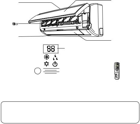
Parts Name
Indoor Unit
air inlet |
panel |
|
air outlet
horizontal louver
display
temp. indicator
cooling indicator |
|
|
|
|
|
drying indicator |
|
|
|
|
|||||
heating indicator |
|
|
|
|
|
|
power indicator |
|
|
|
|
||||
aux.button |
|
|
|
|
|
receiver window |
|
|
|
|
|
||||
F |
C |
ON/OFF
- +
MODE  FAN SWING
 I FEEL /
 SLEEP TEMP TI MERON CLOCK TIMEROFF TURBOLIGHTX-FAN
(Display content or position may be different from above |
remote controller |
graphics, please refer to actual products) |
|
NOTICE:
Actual product may be different from above graphics, please refer to actual products.
6

Operation of Remote Controller |
||||
|
|
|
1 |
ON/OFF |
|
|
|
|
Press it to start or stop operation. |
|
|
|
2 |
- : Press it to decrease temperature |
|
|
|
|
setting. |
|
|
|
3 |
+ : Press it to increase temperature |
|
|
|
|
setting. |
|
|
|
4 |
MODE |
|
|
F |
|
Press it to select operation mode |
|
|
|
(AUTO/COOL/DRY/FAN/HEAT). |
|
|
|
C |
|
|
|
|
5 |
FAN |
|
|
|
HOUR |
||
|
ONOFF |
|
Press it to set fan speed. |
|
1 |
|
|
6 |
SWING |
2 |
OFF |
|
3 |
Press it set swing angle. |
|
|
I FEEL |
||
- |
+ |
|
7 |
|
|
|
|
||
|
|
|
|
|
|
|
|
|
|
|
|
/ |
||
|
|
|
|
|
|
|
|
8 |
||||||
|
|
|
|
|
|
|
|
|
||||||
|
|
|
|
|
|
|
|
|
|
|
Press it to set HEALTH or AIR function. |
|||
4 |
|
|
|
|
|
|
5 |
|
|
SLEEP |
||||
|
|
|
|
|
|
|
9 |
|
||||||
6 MODE |
FAN |
|
|
|
TEMP |
|||||||||
7 |
|
10 |
|
|||||||||||
|
||||||||||||||
|
|
|
||||||||||||
|
|
|
||||||||||||
|
SWING |
IFEEL |
|
|
|
|
TIMER ON |
|||||||
8 |
9 |
|
11 |
|
||||||||||
|
|
|
|
|
|
|
|
|||||||
|
|
|
|
|
|
|||||||||
|
|
/ |
|
|
|
|
|
|
Press it to set auto-on timer. |
|||||
10 |
|
|
|
|
SLEEP 11 |
|
|
|
||||||
|
|
|
|
|
||||||||||
|
|
|
||||||||||||
|
|
|
|
|
|
|
|
CLOCK |
||||||
12 TEMP |
TIMER-ON 13 |
|
12 |
|
||||||||||
13 |
|
Press it set clock. |
||||||||||||
14 |
CLOCK |
TIMER-OFF |
16 |
|
TIMER OFF |
|||||||||
TURBO LIGHT X-FAN |
|
|
|
|
Press it to set auto-off timer. |
|||||||||
|
|
|
|
|
|
|||||||||
|
15 |
|
|
|
|
|
|
TURBO |
||||||
|
|
|
|
14 |
|
|
||||||||
|
|
|
|
|
|
|
|
|
|
|
||||
|
|
|
|
|
|
|
|
|
|
|
LIGHT |
|||
|
|
|
|
|
|
|
|
|
15 |
|
||||
|
|
|
|
|
|
|
|
|
|
|
|
|
Press it to turn on/off the light. |
|
16 X-FAN
7
 Operation of Remote Controller
|
25 |
17 |
24 |
|
|
|
23 |
18 19 20 21 |
22 |
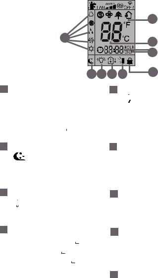
17 MODE icon:
If MODE button is pressed, current operation mode icon
 (AUTO),
  ( COOL),

(DRY),  (FAN) or


 (HEAT
(HEAT
only for heat pump models) will show.
21Up & down swing icon:

 is displayed when pressing
the up & down swing down button. Press this button again to clear the display.
18 SLEEP icon :
is displayed by pressing
the SLEEP button. Press this button again to clear the display.
22 LOCK icon:
 is displayed by pressing "+" and “-” buttons simultaneously. Press them again to clear the display.
19 LIGHT icon:


 is displayed by pressing the
LIGHT button. Press LIGHT button again to clear the display.
20 TEMP icon:
Pressing TEMP button,  (set temperature),
  (indoor ambient temperature)
 (outdoor ambient temperature)
and blank is displayed circularly.
23 SET TIME display:
After pressing TIMER button, ON or
OFF will blink.This area will show the set time.
24 DIGITAL display:
This area will show the set temperature. In SAVE mode, "SE" will be displayed.
25 AIR icon:
 is displayed when pressing the AIR button. Press this button again to clear the display.
8
 Operation of Remote Controller
30 |
29 |
|
28 |
31 |
27 |
|
26 |
26 HEALTH icon:
 is displayed when pressing the
HEALTH button. Press this button again to clear the display.
29 FAN SPEED display:
Press FAN button to select the desired fan speed setting(AUTO-
Low-Med-High). Your selection will be displayed in the LCD windows, except the AUTO fan speed.
|
X-FAN icon: |
|
I FEEL icon: |
27 |
30 |
 is displayed when pressing the X-FAN button. Press this button again to clear the display.

 is displayed when pressing the I FEEL button. Press this button again to clear the display.
28 TURBO icon:
 is displayed when pressing the TURBO button. Press this button again to clear the display.
31 8 Heating icon:
 is displayed when Pressing “TEMP” and “CLOCK” simultaneously in Heat mode.
9
 Operation of Remote Controller
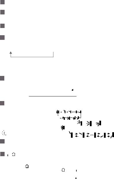
Remote Controller Description
1ON/OFF:
Press this button to turn on the unit . Press this button again to turn off the unit.
2

Press this button to decrease set temperature. Holding it down above 2 seconds rapidly decreases set temperature. In AUTO mode, set temperature is not adjustable.
3+ :
Press this button to increase set temperature. Holding it down above 2 seconds rapidly increases set temperature. In AUTO mode, set temperature is not adjustable.
4 MODE :
Each time you press this button, a mode is selected in a sequence that goes from AUTO, COOL, DRY, FAN, and HEAT *, as the following:
AUTO  COOL
COOL  DRY
DRY  FAN
FAN  HEAT *
*Note:Only for models with heating function.
After energization, AUTO mode is defaulted. In AUTO mode, the set temperature will not be displayed on the LCD, and the unit will automatically select the suitable operation
mode in accordance with the room temperature to make indoor room comfortable. (As for cooling only unit, it won’t have any action when it receives the signal of heating
operation.)
5FAN :
This button is used for setting Fan Speed in the sequence that goes from AUTO, ,
,

 , to
, to 

 , then back to Auto.

 Auto
Auto


 Low speed
 Medium speed

 High speed
6SWING:
Press this button to set up &down swing angle, which circularly changes as below:
OFF |
|
|
|
This remote controller is universal. If any command |
, |
or |
is sent out, |
the unit will carry out the command as |
|
|
|

 indicates the guide louver swings as:
7I FEEL:
Press this button to turn on I FEEL function. The unit automatically adjust temperature according to the sensed temperature. Press this button again to cancel I FEEL function.
8 /
/
Press this button to achieve the on and off of healthy and scavenging functions in operation status. Press this button for the first time to start scavenging function; LCD displays“ ”. Press the button for the second time to start healthy and scavenging
functions simultaneously; LCD displays“ ” and “
 ” . Press this button for the third time to quit healthy and scavenging functions simultaneously.Press the button for the fourth time to start healthy function; LCD display “
 ”. Press this button again to repeat the operation above. (This function is applicable to partial of models)
10
 Loading...