

Page 1
Installation manual
Simrad SU90
Fish nding sonar
www.simrad.com
TECHNOLOGY FOR SUSTAINABLE FISHERIES
Page 2

Page 3

SimradSU90
Installationmanual
Thismanualprovidesyouwiththebasicinformation
requiredtoinstalltheSimradSU90Sonar.Forinformation
aboutthepracticaluseoftheproduct,refertotheSimrad
SU90OperatormanualortheSimradSU90Reference
manual.
AlluserdocumentationisincludedontheUSBmemory
devicethatisprovidedwiththeSimradSU90.Themanuals
canalsobedownloadedfromhttp://www.simrad.com/su90
WARNING:TheSimradSU90sonarmustneverbe
poweredupwhentheshipisindrydock.Thetransducer
willbedamagedifittransmitsinopenair.Toprevent
inadvertentuseofthesonar,pulloutthemainsplugon
theProcessorUnitwheneverthevesselisindrydock.
.
381293/A
2013-09-13
©
KongsbergMaritimeAS
Page 4

Revisionstatus
Documentno:381293/V ersion:A/ISBN-13:978-82-8066-158-6
Rev.A2013–09–13
Firstversion
Copyright
©2013KongsbergMaritimeAS
TheinformationcontainedinthisdocumentremainsthesolepropertyofKongsbergMaritimeAS.Nopart
ofthisdocumentmaybecopiedorreproducedinanyformorbyanymeans,andtheinformationcontained
withinitisnottobecommunicatedtoathirdparty,withoutthepriorwrittenconsentofKongsberg
MaritimeAS.Thedocument,oranypartofit,maynotbetranslatedtoanyotherlanguagewithoutthe
writtenapprovalfromKongsbergMaritimeAS.
Disclaimer
KongsbergMaritimeASendeavourstoensurethatallinformationinthisdocumentiscorrectandfairly
stated,butdoesnotacceptliabilityforanyerrorsoromissions.
Warning
Theequipmenttowhichthismanualappliesmustonlybeusedforthepurposeforwhichitwas
designed.Improperuseormaintenancemaycausedamagetotheequipmentand/orinjury
topersonnel.Allusersmustbefamiliarwiththecontentsoftheappropriatemanualsbefore
attemptingtoinstall,operate,maintainorinanyotherwayworkontheequipment.
KongsbergMaritimeASdisclaimsanyresponsibilityfordamageorinjurycausedbyimproper
installation,useormaintenanceoftheequipment.
Supportinformation
Ifyourequiremaintenanceorrepair,contactyourlocaldealer.Youcanalsocontactususingthefollowing
address:simrad.support@simrad.com.Ifyouneedinformationaboutourotherproducts,visithttp:
//www.simrad.com.Onthiswebsiteyouwillalsondalistofourdealersanddistributors.
SeealsoSupportinformationonpage33.
KongsbergMaritimeAS
www.kongsberg.com
Page 5

Installationmanual
Tableofcontents
ABOUTTHISMANUAL.....................................................13
SIMRADSU90.................................................................15
Systemdescription.................................................................................................16
Systemdiagram......................................................................................................18
Systemunits...........................................................................................................19
Colourdisplay............................................................................................19
ProcessorUnit............................................................................................19
OperatingPanel..........................................................................................19
OperatingPanelpowersupply.....................................................................20
Audioamplierwithloudspeakers...............................................................20
TransceiverUnit.........................................................................................20
HullUnit....................................................................................................20
Transducer.................................................................................................21
Scopeofsupply......................................................................................................21
Mainunitsincludedwiththestandarddelivery.............................................21
Additionalitems.........................................................................................22
Additionalrequireditems.......................................................................................22
Colourdisplay............................................................................................22
UninterruptedPowerSupply(UPS)..............................................................23
Installationtrunk.........................................................................................23
Speedlog...................................................................................................24
Coursegyro................................................................................................24
Optionalitems........................................................................................................25
Hullunit.....................................................................................................25
Installationtrunk.........................................................................................25
Extendedrange...........................................................................................26
Scienticinterface......................................................................................26
Otherperipheralequipment.........................................................................26
Audiooutput..............................................................................................28
Externalmotionreferenceunit(MRU).........................................................30
SecondaryOperatingPanel..........................................................................30
Generalsupplyconditions......................................................................................31
Equipmentresponsibility.............................................................................31
Receipt,unpackingandstorage....................................................................31
Generalinstallationrequirements...........................................................................32
Supplypower.............................................................................................32
UninterruptedPowerSupply(UPS)..............................................................32
Wiring........................................................................................................32
Compassdeviation......................................................................................33
381293/A
3
Page 6

SimradSU90
Noisesources.............................................................................................33
Drydocking...............................................................................................33
Approvalbyclassicationsociety................................................................33
Supportinformation...............................................................................................33
INSTALLATIONPROCEDURE...........................................35
PREPARATIONS..............................................................37
Installationdrawings..............................................................................................38
Necessarytoolsandequipment..............................................................................38
Workerskills...........................................................................................................39
Determingthelocationofthehullunit..................................................................40
Foreandaftlocation...................................................................................40
Athwartshipslocation..................................................................................41
Importantconsiderationsrelatedtonoise......................................................41
Sonarroomrequirements.......................................................................................42
Watertightintegrity.....................................................................................42
Sizeandaccess...........................................................................................43
Heating......................................................................................................43
Insulation...................................................................................................43
Ventilation..................................................................................................43
Cableprotection.........................................................................................44
Electricalinstallationsandlights..................................................................44
Bilgepumpanddecking..............................................................................44
Liftingdevice.............................................................................................44
Communication..........................................................................................44
Sonarroomarrangementexample..........................................................................45
Sonarroomarrangementexample1–Topview............................................45
Sonarroomarrangementexample2–Sideview...........................................46
Hullunitorientationexample.......................................................................47
Acousticnoise........................................................................................................47
Contributingnoisefactors...........................................................................48
Selfnoise...................................................................................................49
Ambientnoise............................................................................................51
Fishinggearnoise.......................................................................................51
Electricalnoise...........................................................................................52
Reverberation.............................................................................................52
Somemeanstoreducethenoise...................................................................52
INSTALLINGTHESONARTRUNK.....................................55
Aboutthesonartrunkinstallation..........................................................................56
Mountingthesonartrunk.......................................................................................57
Mountingthetrunkextension.................................................................................58
Protectingthesonartrunk.......................................................................................59
4
381293/A
Page 7

Installationmanual
Sonartrunkinstallationprinciples..........................................................................59
Installationofatrunkwithopenblister.........................................................60
Installationofatrunkwithoillledblister...................................................61
Sonartrunkinstallationmeasurementsandchecklist............................................62
INSTALLINGTHEHULLUNIT..........................................63
Aboutthehullunitinstallation...............................................................................64
Hullunitfamiliarizationandmainpartsidentication..........................................65
MotorControlUnitfamiliarizationandmainpartsidentication.........................66
Hullunitmodelsoverview.....................................................................................67
Unpackingthehullunitfromitstransportbox......................................................68
Mountingthehullunit............................................................................................70
Bleedingaircock....................................................................................................72
Mountingthemechanicalsupport..........................................................................72
Transduceralignment.............................................................................................73
Visualinspectionofthetransducer........................................................................73
Loweringandhoistingthetransducermanuallyusingthehandcrank.............74
Hullunitinstallationchecklist...............................................................................76
INSTALLINGTHETRANSCEIVERUNIT............................77
INSTALLINGTHEBRIDGEUNITS....................................81
Preparationsforinstallation....................................................................................82
Basicrequirements......................................................................................82
Locationofthecolourdisplay......................................................................82
LocationoftheProcessorUnit.....................................................................83
LocationoftheOperatingPanel...................................................................83
LocationoftheOperatingPanelPowerSupply.............................................84
Locationoftheamplierandloudspeakers...................................................84
Maximumdistancesbetweentheunits...................................................................85
Installationofthecolourdisplay............................................................................85
InstallationoftheProcessorUnit...........................................................................86
InstallationoftheOperatingPanel.........................................................................88
InstallationoftheOperatingPanelPowerSupply.................................................89
Installationoftheamplierandloudspeakers........................................................89
CABLELAYOUTANDINTERCONNECTIONS......................90
Readthisrst!........................................................................................................91
Cableplan...............................................................................................................93
Bridgecables..............................................................................................93
Sonarroomcables......................................................................................94
Listofcables..........................................................................................................95
Cableprocedures..................................................................................................100
ConnectingACmainstotheUninterruptedPowerSupply...........................101
381293/A
5
Page 8

SimradSU90
ConnectingthevideocablefromtheProcessorUnittothecolour
display.....................................................................................................102
ConnectingtheUSBcablefromtheOperatingPaneltotheProcessor
Unit.........................................................................................................103
ConnectingthedualinterfacecablefromtheOperatingPaneltothe
ProcessorUnit..........................................................................................104
ConnectingtheOperatingPanelPowerSupplytotheProcessorUnit...........105
ConnectingACmainsandgroundtotheProcessorUnit..............................106
ConnectingACmainstothecolourdisplay................................................107
ConnectinggroundtotheOperatingPanel..................................................108
ConnectingtheProcessorUnittotheTransceiverUnit................................109
ConnectingACmainstotheTransceiverUnit.............................................111
ConnectingACmainstotheMotorControlUnit........................................112
ConnectingtheTransceiverUnittotheMotorControlUnit.........................113
ConnectingACmainstotheHeatExchanger..............................................114
ConnectingtheEthernetcableforscienticoutput......................................115
Connectingtheaudiocablesforexternalpoweredspeakers.........................116
Connectingthetransducercable.................................................................117
Connectingtheinterfacecablestotheperipheralequipment........................117
MoxaCP114EL-ISerialadaptersetup.................................................................117
Seriallinesupport.....................................................................................118
JumperandDIPswitchsettings.................................................................118
Softwaresetup(WindowsXP)...................................................................118
Softwaresetup(Windows7)......................................................................120
Adaptercable...........................................................................................121
Referencestodetailedcabledrawingsandspecications....................................123
INTERFACINGPERIPHERALEQUIPMENT......................124
Overviewofinterfacesandsupportedtelegramformats......................................125
Telegramsreceivedfromexternaldevices...................................................125
Telegramssenttoexternaldevices.............................................................127
Monitoringandchangingtheinterfacesettings...................................................128
Defaultinterfacesettings...........................................................................128
Changingtheinterfacesettings..................................................................129
MonitoringthetrafconaserialorEthernetline........................................132
Synchronisationwithotheracousticsystems.......................................................135
Settingupthesynchronisationfunction......................................................135
Aboutsynchronisation..............................................................................137
Synchronisationusingaserialline.............................................................138
SU90setupasSlave.................................................................................138
SU90setupasMaster...............................................................................138
Synchronisationsequences........................................................................139
Synchronisationofthesonarclockwithanexternalclock..................................140
OpeningtheInstallationmenu...................................................................141
6
381293/A
Page 9

Installationmanual
Changingthenecessaryparametertoallowforclocksynchronization...........141
Connectingthespeedlogandcoursegyro...........................................................141
Connectingthespeedlog...........................................................................142
Connectingthecoursegyro.......................................................................143
Connectinganexternalmotionreferenceunit(MRU).........................................144
Physicalinstallationofthemotionreferenceunit........................................144
Installationofthemotionreferenceunitcable.............................................144
OpeningtheInstallationmenu...................................................................145
Conguringandtestingtheinterfacetothemotionreferenceunit................145
EnteringthestabilisationoffsetangleintotheSU90....................................146
ConnectingasecondaryOperatingPanel.............................................................147
PartsandtoolsrequiredtoinstallasecondaryOperatingPanel....................147
PhysicalinstallationoftheOperatingPanel................................................148
InstallationoftheOperatingPanelcables...................................................148
OpeningtheInstallationmenu...................................................................149
ConguringandtestingtheinterfacetothesecondaryOperating
Panel........................................................................................................150
CableplanforasecondaryOperatingPanel................................................151
ListofcablesrequiredforthesecondaryOperatingPanel............................152
Establishingemergencyhoistfunctionality..........................................................154
Designingtheemergencyhoistinterface.....................................................154
Circuitboardinterfacedescription.............................................................155
Testingtheinterfacestoperipheraldevices..........................................................156
OpeningtheInstallationmenu...................................................................156
Conguringandtestingtheinterfacetothespeedlog..................................157
Conguringandtestingtheinterfacetothecoursegyro...............................158
Conguringandtestingtheinterfacetothepositioningsystem(GPS)...........159
Conguringandtestingtheinterfacetoatrawlsystem................................160
Conguringandtestingtheinterfacetoacatchmonitoringsystem...............161
Conguringandtestingtheinterfacetoaradiobuoysystem........................161
Conguringandtestingtheinterfacetoaseacurrentmeter..........................162
SETTINGTOWORK.......................................................163
StartinguptheHullUnit......................................................................................164
Hullunitfamiliarizationandmainpartsidentication.................................165
MotorControlUnitfamiliarizationandmainpartsidentication..................166
Functionalcheck.......................................................................................166
Apply3-phaseACpower..........................................................................167
Checkthehoistingmotor's3–phaseACconnections...................................168
Check3–phaseconnectionforcorrectrotation............................................169
ChecktheK301contactoroperation...........................................................170
Verifycorrecthoistandlowerfunctionality................................................171
Startingupthebridgeunits..................................................................................173
381293/A
7
Page 10

SimradSU90
StartingupoftheProcessorUnitforthersttime.......................................173
Settingupthesonartoretrievesimulatedsonarechoes................................174
OpeningtheInstallationmenu...................................................................174
CheckingtheOperatingPanel..............................................................................175
OperatingPanelfunctionaltests.................................................................175
CheckingtheOperatingPanelbacklight.....................................................180
Poweringoffthesonar..............................................................................181
StartinguptheTransceiverUnit...........................................................................181
Checkingthehoist/lowerfunctionality................................................................183
ConnectingtheTransceiverUnittotheProcessorUnit................................183
Selectingwhichhullunittypetobeused....................................................184
Checkingthehoist/lowerfunctionalityfromthebridge................................185
Checkingthehoist/lowerfunctionalityfromthesonarroom........................187
Measuringtheself-noise......................................................................................188
StartinguptheSU90system................................................................................190
PreparationsbeforetheSU90systemisstarted...........................................190
StartinguptheSU90system,bridgeactions...............................................191
StartinguptheSU90system,sonarroomactions........................................192
Alignmentofthesonarpicture.............................................................................193
Adjustingthestabilisationsensoroffset...............................................................194
Estimatingtheoffsetangle........................................................................194
EnteringthestabilisationoffsetangleintotheSU90....................................195
Deningownshipparameters..............................................................................195
Specifyingshipdimensions.......................................................................195
Specifyinginstrumentpositionoffsets........................................................196
OpeningtheInstallationmenu...................................................................196
FINALTESTSANDMEASUREMENTS..............................198
Sourcelevel(SL)measurements..........................................................................199
Preparationsandtesthydrophonedata........................................................199
Testsetup.................................................................................................200
Sonarparameters......................................................................................200
Testprocedure..........................................................................................201
Finalizingtheprocedure............................................................................202
Sourceleveltestresults.............................................................................202
Receivingvoltageresponse(VR)measurements.................................................203
Preparations.............................................................................................203
Sonarparameters......................................................................................203
Testprocedure..........................................................................................204
Finalizingtheprocedure............................................................................205
Receivingvoltageresponsetestresults.......................................................205
Noise/speedcurvemeasurements.........................................................................206
Preparations.............................................................................................206
8
381293/A
Page 11

Installationmanual
Testprocedure..........................................................................................206
Problemswithownoise..........................................................................207
Noise/speedtestresults.............................................................................207
ProcessorUnitbackupandrestore.......................................................................210
AboutSU90backupandrestore.................................................................210
Creatingabackupimageofallthesonarsoftware.......................................211
Restoringthesonarsoftwarefromabackupimage......................................212
ReactivatingtheWindowslicense..............................................................213
CreatingabootableUSBmemorystick......................................................218
TECHNICALSPECIFICATIONS.......................................219
Performancespecications...................................................................................220
Weightsandoutlinedimensions...........................................................................221
Powerspecications.............................................................................................223
Environmentalspecications...............................................................................223
Minimumdisplayrequirements............................................................................224
TELEGRAMFORMATS....................................................226
TelegramsreceivedandsentbytheSU90............................................................227
Coursegyrotelegrams...............................................................................227
Speedlogtelegrams..................................................................................227
GPStelegrams..........................................................................................228
ITIandtrawlsystemtelegram....................................................................228
Echosoundertelegrams.............................................................................229
Windsensortelegrams..............................................................................230
Seacurrenttelegrams................................................................................230
Catchmonitoringsystemtelegrams............................................................230
Buoytelegrams.........................................................................................230
Targetoutputtelegrams.............................................................................230
AbouttheNMEAtelegramformat.......................................................................231
NationalMarineElectronicsAssociation(NMEA)......................................231
NMEAtelegramprinciples........................................................................232
StandardNMEA0183communicationparameters......................................232
NMEAsentencestructure..........................................................................232
SpecicationofNMEAtelegrams.......................................................................233
DBSDepthbelowsurface.........................................................................234
DBTDepthbelowtransducer.....................................................................234
DPTDepth...............................................................................................234
GGAGlobalpositioningsystemxdata.....................................................235
GLLGeographicalpositionlatitude/longitude............................................235
HDGHeading,deviationandvariation.......................................................236
HDMHeading,magnetic...........................................................................237
HDTHeading,true...................................................................................237
MWDWinddirectionandspeed................................................................237
381293/A
9
Page 12

SimradSU90
MWVWindspeedandangle.....................................................................238
RMCRecommendedminimumspecicGNSSdata....................................238
VBWDualgroundandwaterspeed...........................................................238
VHWWaterspeedandheading.................................................................239
VTGCourseoverground&groundspeed..................................................240
VWRRelative(apparent)windspeedandangle..........................................240
ZDATimeanddate..................................................................................240
Proprietarytelegramsandformats.......................................................................241
DBSDepthoftrawlbelowsurface.............................................................242
FS3300Binarydepth................................................................................242
GLLTrawlposition..................................................................................242
HFBTrawlheadropetofootropeandbottom..............................................243
MDSMeasureddatashoal.........................................................................243
MTWWatertemperatureatthetrawl.........................................................244
PSIMP-DPISensordata...........................................................................244
PSIMP-FPISensordata............................................................................246
TDSTrawldoorspread.............................................................................246
TFITrawllling.......................................................................................247
TPCTrawlpositionincartesiancoordinates...............................................247
TPPTrackedtargetpositionormarker.......................................................247
TPTTrawlpositiontruevessel..................................................................248
TS2Trawlspread2...................................................................................248
TTSTrawltoshoaldistance......................................................................248
Proprietarythirdpartytelegramsandformats......................................................250
FurunoCIFSeacurrent.............................................................................250
KaijoVDVCDVectorcurrentdirection......................................................253
RyokoseiRBYBuoyinput........................................................................253
SerpeBSCBuoyinput..............................................................................254
DRAWINGFILE.............................................................255
Cabinetoutlinedrawings......................................................................................256
TransceiverUnitdimensions......................................................................257
ProcessorUnitdimensions........................................................................260
OperatingPaneldimensions......................................................................261
HullUnitdrawings...............................................................................................262
SU92Hullunitdimensionsdrawing...........................................................263
SU93Hullunitdimensionsdrawing...........................................................265
SU92/SU93Mountingtrunkproductiondrawing........................................267
SU92/SU93Extensiontrunkproductiondrawing........................................269
SU92/SU93Blindcoverdrawing...............................................................271
AGENERALSAFETYRULES...............................................272
BEQUIPMENTHANDLING................................................273
Transportation.......................................................................................................274
10
381293/A
Page 13

Installationmanual
Lifting...................................................................................................................274
Storagepriortoinstallationoruse.......................................................................275
Inspection.............................................................................................................276
Unpacking............................................................................................................276
Generalunpackingprocedure....................................................................276
Unpackingelectronicandelectromechanicalunits......................................277
Unpackingmechanicalunits......................................................................277
Unpackingtransducers..............................................................................277
Storageafterunpacking........................................................................................278
Storageafteruse...................................................................................................278
Cleaningcabinets......................................................................................278
Mechanicalunits.......................................................................................279
Cables......................................................................................................279
Internalbatteries.......................................................................................279
Dehumidier............................................................................................280
Coatings...................................................................................................280
Re-packaging........................................................................................................280
Temperatureprotection.........................................................................................280
Circuitboardhandlingandpackaging..................................................................281
Electro-StaticDischarge(ESD)............................................................................282
Disposal................................................................................................................282
CSU90CABLEDETAILS...................................................284
Cablingprinciples.................................................................................................285
Cablestoperipheraldevices.................................................................................285
Positioningsysteminterface......................................................................286
Echosoundersysteminterface...................................................................286
Trawlsonarinterface.................................................................................286
Catchmonitoringsysteminterface.............................................................287
Currentmeterinterface..............................................................................287
Radiobuoysconnectioninterface...............................................................287
Cabledrawings.....................................................................................................288
GenericRS-232Serialline(Threewires)...................................................289
RS-232usedasexternaltriggerinputoroutput...........................................290
GenericRS-422Serialline(Fivewires).....................................................291
MoxaCP114EL-ISeriallineadapter..........................................................292
Mini-jacktophonoaudiocable..................................................................294
Vesselground...........................................................................................295
ACmainswithIEC60320socketandinlineplug.......................................296
3–phaseACmainstoMotorControlUnit...................................................297
ACmainswithIEC320/C7inlineplug......................................................298
OperatingPanelpowersupply...................................................................299
RJ45Ethernet,straight..............................................................................300
381293/A
11
Page 14

SimradSU90
UniversalSerialBus(USB).......................................................................302
DVI–IDisplaycable.................................................................................303
Commercialpoweredspeakersystem.........................................................304
OperatingPanel“Dual”cable....................................................................306
DBASICCABLEREQUIREMENTS......................................307
Cabletrays............................................................................................................308
RadioFrequencyinterference..............................................................................308
Physicalprotection...............................................................................................309
Grounding.............................................................................................................309
Cableconnections.................................................................................................310
Cableterminations................................................................................................310
Cableidentication...............................................................................................310
EINSTALLATIONREMARKS.............................................311
12
381293/A
Page 15

Aboutthismanual
Aboutthismanual
Purpose
Thepurposeofthismanualistoprovidetheinformationandbasicdrawingsrequiredfor
installationoftheSimradSU90.
Formoredetailedinformationaboutthepracticaluseoftheproduct,refertotheSimrad
SU90OperatormanualortheSimradSU90Referencemanual.
Targetaudience
Themanualisintendedfortechnicalpersonnel;qualiedmaintenanceengineersand
technicians.Itisassumedthatthepersonnelisconversantwiththegeneralprinciplesof
maritimeelectronicequipment,inparticularsonar,echosounderandcatchmonitoring
systems.Thepersonnelmustalsobefamiliarwithcomputerhardware,signalprocessing,
interfacetechnologyandtraditionaltroubleshootingonelectronicandmechanical
products.
®
WeassumethatyouarefamiliarwiththeWindows
system,andconversantwithnetworkaddressingandcommunicationprinciples.
Installationinstructions
Theinstructionsprovidedinthismanualmustbefollowedcarefullytoensureoptimal
performance.Asaguide,installationproceduresarepresentedintheordertheyareto
beperformed.
Theequipmentdescribedinthismanualincludesthecompletesystemwithrelevant
cabinets,butnotsystemunitsprovidedlocallybythecustomer,installationshipyardor
localrepresentative.Themanualalsodenestheequipmentresponsibility,andprovides
applicableinstructionsforunpackingandstorage.
Note
®
XP
and/orWindows
®
7operating
Theinstallationinstructionsgiveninthisdocumentmustbeadheredto.Failuretodoso
mayrendertheguaranteevoid.
KongsbergMaritimeASwillacceptnoresponsibilityforanydamageorinjurytothe
system,vesselorpersonnelcausedbyequipmentthathasbeenincorrectlyinstalledor
maintained,orbydrawings,instructionsorproceduresthathavenotbeenprepared
byus.
381293/A
13
Page 16

SimradSU90
Installationdrawings
Detailedvesselspecicmechanicaldrawingsfortheinstallationmustbeprovidedbythe
customer,oranyshipyardcontractedtoperformtheinstallation.
KongsbergMaritimeASmay,onspecialorder,provideassistancetothesedrawings.
Drawingsmustbeapprovedbytheappropriatevesselcerticationauthoritypriorto
installationofthesystem.
Applicablegenericoutlinedimensionandproductionsdrawingsareprovidedinthe
Drawinglechapter.DrawingsmayalsobedownloadedinPDFand/orDWGformats
fromhttp://www.simrad.com
.
Registeredtrademarks
Windows
®
,Windows
®
®
XP
,andWindows
®
7areeitherregisteredtrademarks,or
trademarksofMicrosoftCorporationintheUnitedStatesand/orothercountries.
Simrad
®
,SIMRAD
®
andtheSimrad
®
logoareeitherregisteredtrademarks,or
trademarksofKongsbergMaritimeASinNorwayandothercountries.
Recordofchanges
A2013–09–13:Firstversion
14
381293/A
Page 17

SimradSU90
StudythischaptertofamiliarizeyourselfwiththeSimradSU90.
Topics
•Systemdescriptiononpage16
•Systemdiagramonpage18
•Systemunitsonpage19
SimradSU90
•Scopeofsupplyonpage21
•Additionalrequireditemsonpage22
•Optionalitemsonpage25
•Generalsupplyconditionsonpage31
•Generalinstallationrequirementsonpage32
•Supportinformationonpage33
381293/A
15
Page 18
SimradSU90
Systemdescription
TheSimradSU90
isalongrange
omnidirectionallow
frequencysonar.
Itisdesignedformedium
andlargesizedshing
vessels,preferablyfor
purseseiners,butitis
alsowellsuitablefor
trawlers.
TheSimradSU90
allowsyoutochoose
anoperationalfrequency
between20to30kHz
(in1kHzsteps).The
cylindricalmulti-element
transducerallows
theomnidirectional
sonarbeamtobetilted
electronicallyfrom
+10to–60degrees.
Thisallowsyouto
automaticallytrack
schoolsofsh,and
toobservethewhole
watervolumearound
thevessel.Astabilising
systemisincludedfor
electronicpitchandroll
compensation.
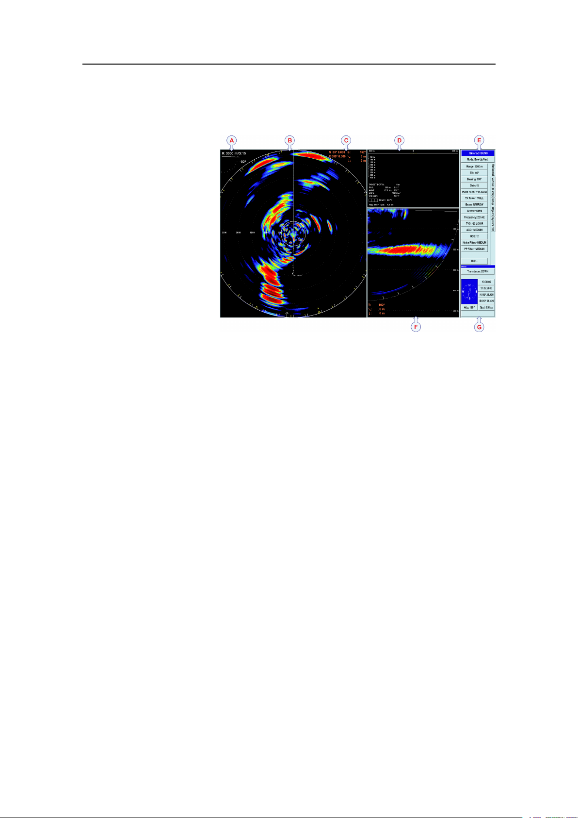
ThisSU90screencaptureshowsyouatypicalcatch
situation.Thepresentationprovidesyouwithalotof
information.
ACurrentrange,transducertiltandgain
BSonarpresentation
CCursor’sposition,bearing(relativetothevessel),
rangeanddepth
DPurseseineandtargetinformation(depthand
estimatedschoolsize),includinginformationfrom
catchmonitoringdepthsensors
EMenusystem
FVerticalview
GNavigationinformationandhullunitposition
TheSimradSU90hasbeendesignedwithnocompromises.ComparedtotheSX90,the
numberofchannelsisincreasedby50%givingthesonaranevenbetterperformance
inselectivityandrange.Thenarrowopeningangle(4,9°at30kHz)andtheincreased
sourcelevel(3dB)makestheSU90averypowerfulandhighresolutionlowfrequency
sonar.ThenarrowbeammakestheSU90evenmoreidealforsearchingshcloseto
thebottomorclosetothesurfaceatlongranges.Italsoprovidesafarbettervertical
viewwithless“bottomclimbing”thatisseenonsonarswithawiderbeam.
Greatemphasishasbeenplacedongivingthebestpossiblesonarpresentationsona
highresolutioncolourdisplay.
TheSU90ProcessorUnitiscontrolledbyMicrosoft’sWindows
whichresultinaexiblechoiceofpresentationmodesforalargerangeofuser
applications.Thesignalprocessingandbeamformingisperformedinafastdigital
16
®
operatingsystem,
381293/A
Page 19

SimradSU90
signalprocessingsystemusingthefulldynamicrangeofthesignals.Inadditiontothe
traditionalsinglefrequencytransceiversystem,theSimradSU90containsanadvanced
frequencymodulatedltersystem(FM).
381293/A
17
Page 20
SimradSU90
SIMRAD
PWR
MENU
SIMRAD
SIMRADSU90
(CD015050-001)
B
C
D
E
G
H
F
A
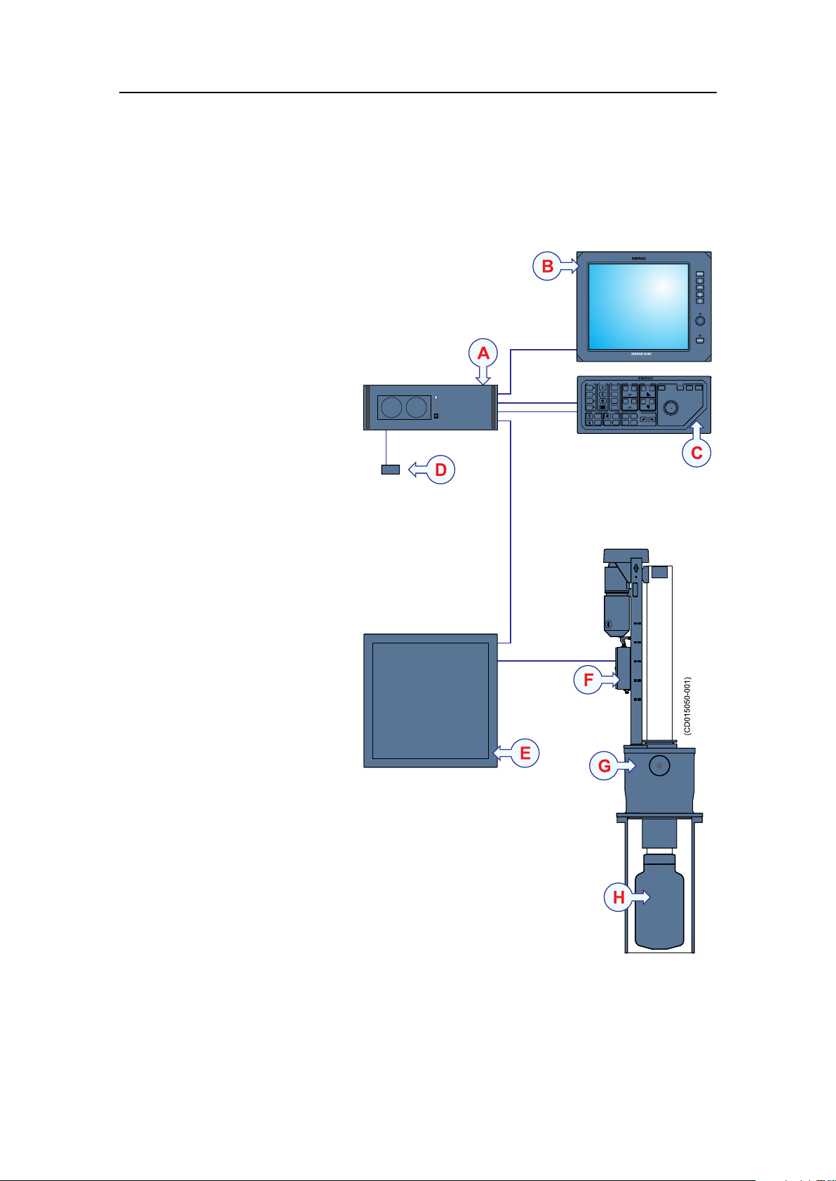
Systemdiagram
AstandardSU90systemdiagramisprovided.Interfacecapabilities,uninterruptedpower
suppliesandpowercablesarenotshown.
AProcessorUnit
BColourdisplay
COperatingPanel
DOperatingPanelPower
Supply
ETransceiverUnit
FMotorControlUnit
GHullUnit
HTransducer
Thecolourdisplayisnot
includedinthestandard
deliveryfromSimrad.Thisis
acommercialitemthatcanbe
purchasedlocally.
18
381293/A
Page 21

Systemunits
TheSimradSU90comprisesthefollowingunits.
Topics
•Colourdisplayonpage19
•ProcessorUnitonpage19
•OperatingPanelonpage19
•OperatingPanelpowersupplyonpage20
•Audioamplierwithloudspeakersonpage20
•TransceiverUnitonpage20
•HullUnitonpage20
•Transduceronpage21
SimradSU90
Colourdisplay
AnycommercialcolourdisplaycanbeusedwiththeSimradSU90system.Thechosen
displaymustbedesignedformaritimeuse,anditmustmeettheminimumperformance
specications.
NotethatthecolourdisplayisnotastandardpartoftheSU90delivery.
ProcessorUnit
TheProcessorUnitisamarinecomputerbasedon
®
theMicrosoftWindows
designedforruggeduse.
Thecomputerisbasedonacommercialdesign,but
thesoftwareandhardwarehasbeenspeciedand
assembledspecicallyforSimradtosuittheSU90requirements.
ThecomputerholdsmultipleUSBportsforusewithfuturesoftwareupgrades.These
USBportswillalsoallowyoutoexportscreencapturesfromthesonar.
®
XP
operatingsystem.Itis
OperatingPanel
TheOperatingPanelcontainsallnecessarycontrol
functionsfornormaloperationoftheSU90.
Thecontrolsarearrangedinlogicalfunctiongroups,
thisgivesaclearandeasyoperation.
ThemajorityoftheSU90functionscanbeaccessed
usingthetrackballontheOperatingPanelandthemenusystemonthedisplay.You
canalsouseastandardcomputermouse.
381293/A
19
Page 22

SimradSU90
OperatingPanelpowersupply
Asmallcommercialpowersupplyisimplementedtoprovidestand-bypowertothe
OperatingPanel.ThepowersupplyisconnectedtotheProcessorUnit.
Audioamplierwithloudspeakers
AnamplierwithoneortwoloudspeakersmaybeconnectedtotheProcessorUnitto
providetheaudiooutput.
Theseoptionalitemsarenotprovidedwiththestandardsonardelivery.
IfstandardcommercialPCloudspeakersareused,thesearenormallypoweredbya
separatepowersupply.
TransceiverUnit
TheSU90TransceiverUnitislocatedinthesonar
room,closetotheHullUnit.
Thetransceiverperformsthetransmissionand
receptioncontrolofthe384transmittersand384
receiverchannels.12identicaltransceiverboards
areused.TheTransceiverUnitalsoholdstwopower
supplies,anEthernetswitch,andalargecapacitorbank.
TwoEthernetcablesareusedforcommunicationwith
theProcessorUnitonthebridge,whileathirdEthernet
cableisusedtocontrolthehullunit.
Thetransducercablesfromthehullunitareplugged
intothesidewalloftheTransceiverUnitcabinetusingaspecialplug.
TheTransceiverUnitismountedonthebulkheadusingpowerfulshockabsorbers.The
connectorsforpowerandinterfacearelocatedatthebottomofthecabinet.
HullUnit
ThestandardSU92HullUnitisdesignedtolowerthetransducer1.2metersbelowthe
ship’shull.Maximumvesselspeedisthen25knots.
TheoptionalSU93HullUnitwilllowerthetransducerto1,6metersbelowthehull.With
theSU93HullUnit,themaximumvesselspeedis20knots.
Whenthesonarisswitchedon,presstheDownbuttonontheOperatingPaneltolower
thetransducerintothewater.Beforethesonarisswitchedoff,presstheUpbuttonon
theOperatingPaneltoretractthetransducerintotheinstallationtrunkforprotection.
Ifyouforgetthis,thetransducerishoistedautomaticallybeforethesonarisswitched
off.Itisalsohoistedautomaticallyifaseriousmalfunctionoccurstothecommunication
betweenthebridgeandthehullunit.
Thetransducercanalsobeloweredtoanyselectedmiddleposition.Incaseofvoltage
failure,thetransducercanberaisedorloweredmanuallybymeansofahandcrank.
20
381293/A
Page 23
SimradSU90
ThesensorfortheelectronicstabilisationofthesonarbeamsishousedintheMotor
ControlUnit,whichismountedontheHullUnit.
Caution
Ifthetransducerhitslargerobjectsorbottom,thetransducershaftmaybe
bent,or-inworstcase-itcanbebrokenoff.Abrokentransducershaftwill
causewaterleakagethroughthetopoftheshaft.
Insuchcases,donotraisethetransducershafttoitsupperposition.
Topreventseriousdamage,youmusthaveawaterpumpandawarning
systeminthesonarroom.
Transducer
ThecylindricalTransducerallowsthesonarbeamtogivefull360degreescoverageof
thewatervolumefrom+10anddownto-60degrees.
Scopeofsupply
PleaseobservethestandardandoptionalpartsprovidedwiththeSimradSU90delivery.
Topics
•Mainunitsincludedwiththestandarddeliveryonpage21
•Additionalitemsonpage22
Relatedtopics
•Additionalrequireditemsonpage22
•Optionalitemsonpage25
Mainunitsincludedwiththestandarddelivery
Partnumber
SH8-203593
382924
381908
373017
Note
ThestandarddeliveryincludesanSU92hullunitwith4.6mtransducercable.Other
hullunitsandcablelengthsareoptional.
Part/unitnameanddescription
OperatingPanel
ProcessorUnit
TransceiverUnit
SU92HullUnit(with4.6mtransducercable)
Relatedtopics
•Additionalrequireditemsonpage22
•Optionalitemsonpage25
381293/A
21
Page 24

SimradSU90
Additionalitems
Requireditems
SeveraladditionalitemsarerequiredfortheSU90operation.Theseitemsarenormally
notsuppliedbySimrad.Theitemsare:
•Colourdisplayonpage22
•UninterruptedPowerSupply(UPS)onpage23
•Installationtrunkonpage23
•Speedlogonpage24
•Coursegyroonpage24
Optionalitems
Severaloptionalitemsmaybeused:
•Installationtrunkonpage25
•Extendedrangeonpage26
•Scienticinterfaceonpage26
•Otherperipheralequipmentonpage26
•Audiooutputonpage28
•Externalmotionreferenceunit(MRU)onpage30
•SecondaryOperatingPanelonpage30
Additionalrequireditems
Thefollowingadditionalitemsarerequiredforafullyoperationalsystem,butthey
arenotincludedinthestandarddelivery:
Topics
•Colourdisplayonpage22
•UninterruptedPowerSupply(UPS)onpage23
•Installationtrunkonpage23
•Speedlogonpage24
•Coursegyroonpage24
Colourdisplay
TheSimradSU90requiresaVGAorDVIcolourdisplaywitharesolutionofatleast
1280x1024pixels.
TheSU90ProcessorUnitofferstwovideooutputs.Asecondarydisplaymaythen
bemountedatanotherlocationonthevessel.Thetwodisplaywillalwaysshowthe
presentation.
same
22
381293/A
Page 25

SimradSU90
IfyoualsowishtocontroltheSU90fromthissecondarydisplaylocation,youcanadd
anextraOperatingPanel.
Relatedtopics
•SecondaryOperatingPanelonpage30
UninterruptedPowerSupply(UPS)
InordertoensurecontinuousoperationoftheSimradSU90independentofvarying
qualityofthevessel'smainssupply,theuseofuninterruptedpowersupplies(UPS)is
required.
Twouninterruptedpowersupplyunitsareused:
•Oneisusedtopowerthebridgeunits.
•OneisusedtopowertheTransceiverUnit.
Important
Uninterruptedpowersupply(UPS)unitsarenotincludedinthestandardSU90delivery.
Severalcommercialtypesareavailable.TochoosethebestUPSfortheSU90
installation,considerenvironmentalconditions,spaceavailable,theavailabilityand
durationofthebatteries,andthepowerrequirementsoftheSU90units.
TheminimumspecicationsfortheUninterruptedPowerSupply(UPS)are:
•Inputvoltage:Musttvesselsupplyvoltage
•Outputvoltage:230Vac,50Hz
•Outputpower:
–Bridgeunits:1000W
–Sonarroomunits:1500W
•Outputrequirement:TheACoutputvoltagemustbeasinewave
Relatedtopics
•Powerspecicationsonpage223
Installationtrunk
Theinstallationtrunkrequiredforthehullunitinstallationisnotincludedinthestandard
delivery.
Theinstallationtrunkmaybefabricatedbytheshipyard,orsuppliedbySimradasan
option.Themechanicaldrawingsofthetrunkandblindcoverareincludedinthis
manual.TheSimradSU90sonarisdeliveredwithoutadomesystem.
TheoptionaltrunkofferedbyKongsbergMaritimeisapprovedbyDetNorskeV eritas
(DNV),andincludesablindcoverandagasket.
Relatedtopics
•Installationtrunkonpage25
381293/A
23
Page 26

SimradSU90
Speedlog
Inordertooperatecorrectly,theSimradSU90requiresinputfromaspeedlog.Inmost
casesasuitablesensorisalreadyinstalledonthevessel.Adifferentialglobalpositioning
system((D)GPS)canalsobeused.
Speedloginterfaceparameters:
•Serialline:StandardNMEA0183telegramformat
Relatedtopics
•Connectingthespeedlogonpage142
•Conguringandtestingtheinterfacetothespeedlogonpage157
Coursegyro
Inordertooperatecorrectly,theSimradSU90requiresinputfromacoursegyro.Inmost
casesasuitablesensorisalreadyinstalledonthevessel.
Coursegyrointerfaceparameters:
•Serialline:StandardNMEA0183telegramformat
Ifthecoursegyroinstalleddoesnotoutputthecorrectserialinterfaceformat,anoptional
gyrointerfaceboxisavailable.Itwillconvertthefollowingsynchroandstepping
gyrosignals:
•3-phasesynchrosignal,20to150VL-L,50/60/400Hz,gearration1:360or1:180
•3-phasesteppersignal,20to150VL-L,gearration1:360or1:180
Orderinginformation
LR40Gyrointerface
298-078535
Relatedtopics
•Connectingthecoursegyroonpage143
•Conguringandtestingtheinterfacetothecoursegyroonpage158
24
381293/A
Page 27

Optionalitems
Thefollowingoptionalequipmentandfunctionalitymaybeorderedatanadditional
chargetoaugmentthestandardSimradSU90systemdelivery,orpurchasedlocally
bytheinstallationshipyardorenduser.
Topics
•Installationtrunkonpage25
•Extendedrangeonpage26
•Scienticinterfaceonpage26
•Otherperipheralequipmentonpage26
•Audiooutputonpage28
•Externalmotionreferenceunit(MRU)onpage30
•SecondaryOperatingPanelonpage30
SimradSU90
Hullunit
ThestandardSU92HullUnitcanbelowered1.2metersataspeedof21knots.The
mountingangehas24boltswithpitchcentrediameter(PCD)680mm.Otherhull
unitsareavailableaslistedbelow.
HullunitsavailablefromKongsbergMaritime
HullUnitSpecicationsOrderno.
SU92*1.2m,21knots,24bolts,PCD680mm,4.6mtransducercable
SU92
SU93
SU93
(*=SU92with4.6mtransducercableisthestandardhullunit)
1.2m,21knots,24bolts,PCD680mm,7mtransducercable
1.6m,16knots,20bolts,PCD620mm,4.6mtransducercable
1.6m,16knots,20bolts,PCD620mm,7mtransducercable
373017
386420
373018
386422
Installationtrunk
Theinstallationtrunkmaybefabricatedbytheinstallationshipyard,orsuppliedby
KongsbergMaritime.Thesameinstallationintrunkisusedforallhullunits.
IfyouarereplacinganSX90orSP90sonarwithanewSU90,youcanuseyourexisting
trunk.However,duetothelargertransducerontheSU90sonar,atrunkextensionmust
beused.
OptionalinstallationtrunksavailablefromKongsbergMaritime
Trunktype
SU92/SU9324bolts,PCD680mm
Extension24bolts,PCD680mm
SpecicationsOrderno.
Relatedtopics
•Mountingthetrunkextensiononpage58
381293/A
376655
374676
25
Page 28

SimradSU90
•SU92Hullunitdimensionsdrawingonpage263
•SU93Hullunitdimensionsdrawingonpage265
•SU92/SU93Mountingtrunkproductiondrawingonpage267
•SU92/SU93Extensiontrunkproductiondrawingonpage269
•SU92/SU93Blindcoverdrawingonpage271
Extendedrange
Duetointernationalregulations,sonarswithoperationalrangeexceeding5000meters
canonlybeexportedonlicense.
ForthisreasonthestandardrangeontheSU90hasbeenlimitedto4500meters.
However,ifanexportlicenceisobtained,themaximumrangecanbeextendedto
8000meters.
Orderinginformation
Extended8000mrange
314506
Scienticinterface
TheScienticOutputisdesignedforresearchpurposes.Whenactivated,thefollowing
dataareavailableonanEthernet(LAN)output:
•Beamdata
•Targetdata
•Ownshipdata
•Geardata
ThescienticoutputoptionmayalsoincludesoftwareforaScienticDataLogger.
Orderinginformation
Scienticinterface
KIT-203477
Otherperipheralequipment
TheSimradSU90providesseveralseriallines.Twooftheseareusedtointerfacetothe
speedlogandcoursegyro.Theremainingseriallinescanbeusedtocommunicate
withotherperipheralequipment.
26
381293/A
Page 29

Thisequipmentmayforexampleinclude:
•DifferentialGlobalPositioningSystem((D)GPS)
•Motionreferenceunit(MRU)
•Echosounder
•Catchmonitoringsystem
•Trawlsonar
•Currentmetersystem
•Radiobuoysystem
Alltheseperipheralsmaybeconnectedusingtheseriallines.Mostofthemwill
communicatebymeansofthestandardNMEA0183format.
Notethatperipheralequipmentandsensorsmustbepurchasedlocallybytheinstallation
shipyardorenduser.
SimradSU90
DifferentialGlobalPositioningSystem((D)GPS)
A(D)GPSmaybeinterfacedwiththeSimradSU90sonartoestablishthevessel’s
positionandprovidecursorandmarkerlatitudeandlongitude.
Inadditiontonavigationaldata,the(D)GPSmayalsobeusedfortheinputofspeedlog
information.Most(D)GPSareequippedtopresentcourseinformation,butthisdatais
generallytooinconsistenttoprovideastablesonarpresentation.
Relatedtopics
•Positioningsysteminterfaceonpage286
Motionreferenceunit(MRU)
TheSU90offersabuilt-inmotionsensortoprovidestabilisationofthesonarbeams.
Youmayincreasetheefciencyandaccuracyifyouinstallaseparatemotionreference
unit(MRU).TheSU90providesaninterfacetotheMRU3sensormanufacturedby
KongsbergMaritime.Relevantinstallationproceduresareincludedinthismanual.
Relatedtopics
•Externalmotionreferenceunit(MRU)onpage30
•Connectinganexternalmotionreferenceunit(MRU)onpage144
Catchmonitoringsystem
Toprovidetrawlandpurseseinedepthinformationonthesonar’sdisplay,thefollowing
Simradcatchmonitoringsystemsmaybeconnected:
•SimradPISeriesCatchmonitoringsystems
•SimradITIIntegratedTrawlInstrumentationsystem
Relatedtopics
•Catchmonitoringsysteminterfaceonpage287
381293/A
27
Page 30

SimradSU90
Trawlsonar
Toprovidetrawlinformationonthesonar’sdisplay,oneofthefollowingSimradtrawl
systemsmaybeconnected:
•SimradFS903Trawlsonar
•SimradFS3300Trawlsonar
•SimradFS20/25Trawlsonar
•SimradFS70Trawlsonar
Relatedtopics
•Trawlsonarinterfaceonpage286
Currentmetersystem
Acurrentmetersystemmaybeconnectedtothesonartodisplaythedirectionandspeed
oftheseacurrentsonvariousdepths.Thefollowingcurrentsystemcanbeconnected:
•KaijoDCG-200
Relatedtopics
•Currentmeterinterfaceonpage287
Radiobuoysystem
AGPSbasedradiobuoysystemmaybeconnectedtothesonartoshowthepositionand
buoydataonthedisplay.Thefollowingbuoysystemscanbeconnected:
•SERPE
•Ariane
•Ryokusei
Relatedtopics
•Radiobuoysconnectioninterfaceonpage287
Audiooutput
Topics
•Abouttheaudiooutputonpage29
•PoweredspeakersystemforPCuseonpage29
•Stereosystemwithamplierandtwoormoreloudspeakersonpage29
Relatedtopics
•Mini-jacktophonoaudiocableonpage294
•Commercialpoweredspeakersystemonpage304
28
381293/A
Page 31

SimradSU90
SIMRAD
PWR
MENU
SIMRAD
SIMRAD
(CD015043-021)
Abouttheaudiooutput
Theaudiooutputmustthereforebeconnectedtoapoweredaudiosystem.Thesystem
mustincludeavolumecontrol,astheaudiooutputlevelfromthesonarisxed.The
audiooutputlevelcannotbecontrolledbytheAudiooffbuttonontheOperatingPanel,
asthisbuttonwillsilencetheaudiooutputcompletely.
Donotconnectaloudspeakerdirectlytotheaudiooutput.Thismaydamagetheaudio
outputcircuitry.
Werecommendthatoneofthefollowingaudiosystemsisused:
•CommercialpoweredspeakersystemforPCuse
•Commercialstereosystemwithamplierandtwo(ormore)loudspeakersand/or
headphones
PoweredspeakersystemforPCuse
AcommercialpoweredspeakersystemforPCusecanbeobtainedfromalmostanykind
ofshopforelectricappliances,homestereoorcomputers.
Thenumberofspeakers,sizeandpoweroutputcanbeselectedtosuitthecrew
preferences.Thelocationofthespeakersmustbedecidedtoallowforeasyadjustment
oftheaudiolevel.
Stereosystemwithamplierandtwoormoreloudspeakers
Ifastereosystemisalreadyinstalledonthebridge,theaudiooutputfromtheSU90
canbeconnectedtoanauxiliaryinput.
381293/A
29
Page 32

SimradSU90
SIMRAD
PWR
MENU
SIMRAD
SIMRADSX90
(CD015043-022)
Theadvantageofthissetupisthatmoststereosystemsareprovidedwitharemote
control,andthisallowsforeasyadjustmentoftheaudiolevel.
Externalmotionreferenceunit(MRU)
Bydefault,theSU90usesabuilt-inmotionreferencedetectormountedonthehullunit.
Forimprovedaccuracy,andexternalmotionreferenceunit(MRU)maybeused.
ThemotionreferenceinterfacefunctionalityontheSU90hasbeendesignedtomatch
theMRUsmanufacturedbyKongsbergSeatex.Descriptionsofallavailabletypesare
providedonhttp://www.km.kongsberg.com/seatex
.TheMRUinterfaceintheSU90
willhoweverallowyouuseanytypeofsensorprovidedthatitoutputstheEM3000
datagramformat.
Relatedtopics
•Otherperipheralequipmentonpage26
•Connectinganexternalmotionreferenceunit(MRU)onpage144
SecondaryOperatingPanel
AsecondaryOperatingPanelmaybeconnected
totheSU90ProcessorUnit.Thismaybeusefulin
conjunctionwithasecondarydisplayifyouwishto
controltheSU90fromtwodifferentlocationsonyour
vessel.
Thesecondaryoperatingpanelwillallowyoutodoallsonaroperationsexceptpower
on/off.
Orderinginformation
SecondaryOperatingPanel(kitwithallparts)
Relatedtopics
•ConnectingasecondaryOperatingPanelonpage147
30
372980
381293/A
Page 33

Generalsupplyconditions
ThefollowinggeneralsupplyconditionsapplytothisSimradSU90delivery.
Topics
•Equipmentresponsibilityonpage31
•Receipt,unpackingandstorageonpage31
Equipmentresponsibility
Theshipyardperformingtheinstallationand/orequipmentdealerbecomesfully
responsiblefortheequipmentuponreceiptunlessotherwisestatedinthecontract.
Thedurationofresponsibilityincludes:
•Theperiodoftimetheequipmentisstoredlocallybeforeinstallation.
•Duringtheentireinstallationprocess.
SimradSU90
•Whilecommissioningtheequipment.
•Theperiodoftimebetweencommissioningandthenalacceptanceoftheequipment
bytheenduser(normallytheownerofthevesselwhichtheequipmenthasbeen
installed).
Unlessotherarrangementshavebeenmadeinthecontract,theSimradSU90guarantee
period(asspeciedinthecontract)beginswhentheacceptancedocumentshavebeen
signed
Receipt,unpackingandstorage
Uponacceptingshipmentoftheequipment,theshipyardand/orthedealershouldensure
thatthedeliveryiscompleteandinspecteachshippingcontainerforevidenceofphysical
damage.Ifthisinspectionrevealsanyindicationofcrushing,dropping,immersionin
wateroranyotherformofdamage,therecipientshouldrequestthatarepresentative
fromthecompanyusedtotransporttheequipmentbepresentduringunpacking.
Allequipmentmustbeinspectedforphysicaldamage,i.e.brokencontrolsandindicators,
dents,scratchesetc.duringunpacking.Ifanydamagetotheequipmentisdiscovered,the
recipientshouldnotifyboththetransportationcompanyandKongsbergMaritimesothat
KongsbergMaritimecanarrangeforreplacementorrepairofthedamagedequipment.
Onceunpacked,theequipmentmustbestoredinacontrolledenvironmentwithan
atmospherefreeofcorrosiveagents,excessivehumidityortemperatureextremes.The
equipmentmustbecoveredtoprotectitfromdustandotherformsofcontamination
whenstored.
Formoreinformation,seetheinformationrelatedtoequipmenthandling.
Relatedtopics
•Equipmenthandlingonpage273
381293/A
31
Page 34

SimradSU90
Generalinstallationrequirements
ThefollowinggeneralinstallationrequirementsareapplicabletothisSU90delivery.
Topics
•Supplypoweronpage32
•UninterruptedPowerSupply(UPS)onpage32
•Wiringonpage32
•Compassdeviationonpage33
•Noisesourcesonpage33
•Drydockingonpage33
•Approvalbyclassicationsocietyonpage33
Supplypower
Thesupplyvoltagetotheequipmentistobekeptwithin±10%oftheinstallation’s
nominalvoltage.Maximumtransientvoltagevariationsonthemainswitchboard’s
bus-barsarenottoexceed-15%to+20%ofthenominalvoltage(exceptunderfault
conditions).
UninterruptedPowerSupply(UPS)
TheSimradSU90system(exceptthehullunit)mustbepoweredusinganUninterrupted
PowerSupply(UPS)withsinewaveoutput.
TheUninterruptedPowerSupplymusthavethecapacitytoindependentlymaintain
powertothesystemforaminimumof10minutes.ThisensuresthattheSU90canbe
switchedoffinacontrolledmannerintheeventofapowerfailure.
Wiring
Allcablesrunningbetweensystemcabinetslocatedindifferentroomsand/orondifferent
decksmustbesupportedandprotectedalongtheirentirelengthsusingconduitsand/or
cabletrays.Notethatthecablesmustnotbeinstalledinthevicinityofhigh-power
suppliesandcables,antennacablesorotherpossiblesourcesofinterference.
Formoredetailedinformationaboutcablesandwiring,refertothebasiccable
requirements.
Relatedtopics
•Basiccablerequirementsonpage307
32
381293/A
Page 35

SimradSU90
Compassdeviation
Oncetheinstallationiscomplete,thevesselmustbeswungwiththesysteminboth
theoperativeandinoperativemodes.Theshipownerandcaptainareresponsiblefor
updatingthedeviationtableaccordinglywithregardtothevessel’snationalregistryand
correspondingmaritimeauthority.
Noisesources
Thevessel’shull,rudder(s)andpropeller(s)shouldbethoroughlyinspectedindrydock
priortoinstallation.
Roughnessbelowthewater-linedeformitiesintheshellplatingandprotrudingobstacles
cancreateunderwaternoise.Thesesourcesofturbulencemustbesmoothedorremoved
asbestaspossible.Itisespeciallyimportantthatthepropeller(s)isnotpittedordamaged.
Relatedtopics
•Acousticnoiseonpage47
Drydocking
Makesurethatampleclearanceunderthesonartrunkand/orprotectionblisteris
providedwhendrydockingthevessel.
Avoidlocatingsupportingblocksorstructuresinthevicinityofthisequipment.
Note
Thelocationofthesonartrunkmustbenotedonthevessel’ sdockingplanforfuture
reference.
Priortodrydocking,powerdownallhydroacousticsystems,andlabeleachsystem
accordinglytopreventaccidentalpoweron.
Removecircuitbreakersifnecessary.
Approvalbyclassicationsociety
TheSimradSU90sonartrunkinstallationmustbeapprovedbyDetNorskeVeritas
(DNV)oranotherclassicationsociety.
Theshipownerandshipyardperformingtheinstallationareresponsibleforobtaining
theinstallationapproval.
Supportinformation
IfyouneedtechnicalsupportforyourSimradSU90youmustcontactyourlocal
dealer,oroneofoursupportdepartments.Alistofallourdealersisprovidedon
http://www.simrad.com.
381293/A
33
Page 36

SimradSU90
Norway(Mainofce)
•Companyname:KongsbergMaritimeAS/Simrad
•Address:Strandpromenaden50,3190Horten,Norway
•Telephone:+4733034000
•Telefax:+4733042987
•E-mailaddress:simrad.support@simrad.com
•Website:http://www.simrad.no
Spain
•Companyname:SimradSpain
•Address:PoligonoPartidaTorres38,03570Villajoyosa,Spain
•Telephone:+34966810149
•Telefax:+34966852304
•E-mailaddress:simrad.spain@simrad.com
•Website:http://www.simrad.es
USA
•Companyname:KongsbergUnderwaterTechnologyInc/SimradFisheries
•Address:1921033rdAveW,Lynnwood,WA98036,USA
•Telephone:+14257121136
•Telefax:+14257121193
•E-mailaddress:simrad.usa@simrad.com
•Website:http://www.simrad.com
Malaysia
•Companyname:KongsbergMaritimeMalaysiaSdn.Bhd
•Address:Unit27-5SignatureOfces,TheBoulevard,MidV alleyCity,Lingkaran
SyedPutra,59200KualaLumpur,Malaysia
•Telephone:+6564117488
•Telefax:+60322013359
•E-mailaddress:simrad.asia@simrad.com
•Website:http://www.simrad.com
34
381293/A
Page 37

Installationprocedure
Installationprocedure
TheSimradSU90isacomplexandadvancedproductforprofessionaluse.
Anoverallinstallationprocedureisprovidedbelow.Theproceduredoesnotdescribe
anydetailedtasks,butreferstotherelevantproceduresinthismanual.
Note
Inordertoobtainmaximumsafetyandperformance,itisveryimportantthatthe
installationproceduresinthismanualarecompliedto,andthatthetasksarecarried
outinthesuccessiontheyaredescribed.Thevesselownermustmakesurethatthe
installationshipyardholdstheapplicablecompetencetoperformtheinstallation,and
thattheapplicablemaritimeauthoritiesareavailabletoverifyandcertifytheinstallation.
ObservethebasicrequirementsinGeneralsafetyrulesonpage272!
1Basedonthevesseldrawingsandbestpractice,determinewherethehullunitshall
belocated.Necessaryconsiderationsmustbetakentoavoidacousticandelectric
disturbances.Makesurethatthesonarroommeetsthespecicationsprovided.
→Preparationsonpage37
2Performthephysicalinstallationofthesonartrunk.Theinstallationshipyardmust
provideallnecessaryinstallationdrawingsinordertocarryoutthisoperation,andif
required,thesedrawingsmustbeapprovedbytheapplicablemaritimeauthorities.
Thetrunkpenetratesthehull,anditisthereforeacrucialpartofthehullunit
assembly.
→Installingthesonartrunkonpage55
3Installthehullunit.Duetoitsphysicalsizeandweight,andthefactthatthetrunk
penetratesthevesselhull,itisveryimportantthatthehullunitisinstalledand
securedproperly.
→Installingthehullunitonpage63
4InstalltheTransceiverUnit.
→InstallingtheTransceiverUnitonpage77
5Installthebridgeunits.
→Installingthebridgeunitsonpage81
381293/A
35
Page 38

SimradSU90
6Performthesystemcabling.Observetheproceduresandcableplans,thedetailed
cabledrawingsandthegeneralrequirementsforthecabling.
→Cablelayoutandinterconnectionsonpage90
→SU90cabledetailsonpage284
→Basiccablerequirementsonpage307
7Performthe“settingtowork”procedures.
Note
InordertosetuptheSU90inasafeandcorrectmanner,theseproceduresmustbe
compliedto!
→Settingtoworkonpage163
8Connecttheperipheralunits.Observethesetupandtestprocedures,thedetailed
cabledrawingsandthegeneralrequirementsforthecabling.
→Interfacingperipheralequipmentonpage124
→SU90cabledetailsonpage284
→Basiccablerequirementsonpage307
9Checkthesourcelevelandreceivingvoltageresponse,andmakethenoise/speed
measurements.
→Finaltestsandmeasurementsonpage198
10Createabackupofallthesoftwareandinstallationsetupparametersonthe
ProcessorUnit.
→ProcessorUnitbackupandrestoreonpage210
11FillinandsigntheInstallationRemarksform,andsendittoSimrad'ssupport
departmentasspeciedontheform.
→Installationremarksonpage311
36
381293/A
Page 39

Preparations
Preparations
Note
Ifyouareinstallingthehullunitonapreviouslyttedinstallationtrunk,rstreadthe
informationaboutsonarroomrequirements.ThenproceedtotheHullUnitinstallation
description.
ThischapterprovidestheinformationnecessarytoplantheinstallationoftheSimrad
SU90accordingtoKongsbergMaritime’srequirements.
Correctinstallationofthehullunitandtransducerisvitaltothesystemperformance.
Severalvariablesmustbetakenintoconsideration,themostimportantofwhichisthe
vessel’sconstruction.Thisguidecanbeusedtoselectthebestlocationforthehull
unitandtransducer.
Topics
•Installationdrawingsonpage38
•Necessarytoolsandequipmentonpage38
•Workerskillsonpage39
•Determingthelocationofthehullunitonpage40
•Sonarroomrequirementsonpage42
•Sonarroomarrangementexampleonpage45
•Acousticnoiseonpage47
381293/A
37
Page 40

SimradSU90
Installationdrawings
Allinstallationdrawingsmustbesuppliedbytheshipyardperformingtheinstallation.
Note
Theinstallationshipyardmustprovideallnecessaryinstallationdrawings,andif
required,thesemustbeapprovedbytheapplicableauthorities.
Note
Theinstallationmustbeapprovedbythevessel’ snationalregistryandcorresponding
maritimeauthorityand/orclassicationsociety.Theshipownerandshipyardperforming
theinstallationareresponsibleforobtainingandpayingforinstallationapproval.
KongsbergMaritimeoffersfreeadviceforinstallationplanning.Proposedarrangements
maybesentforcommentaryorsuggestionssuppliedbyKongsbergMaritime.The
followingdrawingsshouldbesubmittedshouldassistanceberequested:
•Generalarrangement
•Bodyplananddrawingsofrelevantbottomtanksandcofferdams
•Linesplan
Relatedtopics
•Drawingleonpage255
Necessarytoolsandequipment
TheinstallationoftheSimradSU90musttakeplaceindrydock,andtheworkmust
bedonebyaqualiedshipyard.
InordertodotheSU90installation,allnecessarytoolsandequipmentformechanical
hullwork,cabinetinstallationandelectricalwiringmustbeavailable.Itisnotpractical
toprovideadetailedlistofallnecessarytoolsandequipment.However,youmustmake
surethatthefollowingspecializedtoolsareavailable.
•Allnecessarytoolsanditemsrequiredforwelding
•Acranecapableofliftingtheentirehullunit
38
381293/A
Page 41

Preparations
Workerskills
TheinstallationoftheSimradSU90isademandingtask,anditisveryimportantthatthe
shipyardworkersthatareinvolvedintheworkarecompetent.
Asaminimum,thefollowingcertiedcraftsmenmustbeavailable:
•Navalarchitects
•Welders
•Electricians
381293/A
39
Page 42

SimradSU90
Determingthelocationofthehullunit
Observegeneralrecommendationsrelatedtothephysicallocationofthehullunit.
Topics
•Foreandaftlocationonpage40
•Athwartshipslocationonpage41
•Importantconsiderationsrelatedtonoiseonpage41
Foreandaftlocation
Thehullunitshouldpreferablybelocatedwithin1/3to1/10ofthevessel’sLength
BetweenPerpendiculars(LBP)fromitsForwardPerpendicular(FP).Deviationsshould
notbemadewithoutconsultingKongsbergMaritime.
Locationofthehullunit
AWaterlevelatnormaltrim
BWeldingmarkstoindicatehullunitlocationwhendocking
CLengthBetweenPerpendiculars(LBP)
D1/3to1/10ofLBP
40
381293/A
Page 43

Preparations
Athwartshipslocation
ThehullunitmaybelocatedontheCentreLine(CL)ofthevessel,oralongsideitskeel.
Note
Iftheinstallationisoffsetfromthevessel’ scentreline,makesurethattransducer
transmissionandreceptionwillnotbeobstructedbythekeel.
Importantconsiderationsrelatedtonoise
Theinstallationtrunkmustbeinstalledsothatitwillremainverticalundernormal
operatingconditions.Theprimarysourcesofunderwaterdisturbance(otherthana
vessel’smainpropellerandbow/sternthruster)thataffectSU90receptionare:
•Mainorbilgekeels
•Zincanodes
•Coolingelementsprotrudingfromthehull
•Equipmentsuchassonartransducersandpilottubes
•Seachests
•Overboarddischarges
•Dentsinthehull
Allappendagestothehull,indentationsandpipein/outletsarepotentialsourcesof
underwaternoise.Theymayactasresonantcavitiesamplifyingnoiseatcertain
frequencies,createcavitationorturbulence.Transducersshouldnotbelocatedinthe
vicinityofsuchobjectsandespeciallynotimmediatelyaftofthem.
Relatedprocedures
•Acousticnoiseonpage47
381293/A
41
Page 44

SimradSU90
Sonarroomrequirements
The“sonarroom”isthecompartmentinwhichtheTransceiverUnitandthehullunit
areinstalled.
ObservetheseminimumrequirementstoobtainsuitableworkingconditionsforSimrad
SU90installation,useandmaintenance.
Itisstronglyrecommendedtouseadedicatedcompartmenttohousethehullunitandthe
TransceiverUnit.Thesetwounitsmustalsobeinstalledrelativelyclosetoeachother
duetothelimitedlengthofthetransducercables.
Topics
•Watertightintegrityonpage42
•Sizeandaccessonpage43
•Heatingonpage43
•Insulationonpage43
•Ventilationonpage43
•Cableprotectiononpage44
•Electricalinstallationsandlightsonpage44
•Bilgepumpanddeckingonpage44
•Liftingdeviceonpage44
•Communicationonpage44
Watertightintegrity
Thesize,locationanddesignofthesonarroommustfullallrequirementstothe
vessel’swatertightintegrity.Intheeventofamajorleakinthesonarroom,itmustbe
possibletocloseallwatertighthatchesand/ordoorstothesonarroomtomaintainthe
vesselstabilityandsafety.
Thephysicalsizeofthesonarroommustbelimited,sothatintheeventofamajor
leak,theoodingofthesonarroomwillnotinduceinstability,orcausethevesselto
capsizeorsink.
Ensurethatallwatertightdecksandbulkheadsareinspectedperiodicallytoverifythat
therearenounprotectedopeningsorimproperpenetrationsthatwillallowprogressive
oodingfromthesonarroom,andthatthewatertightdoorsandhatchesareinplaceand
inworkingorder.
Ensurebilgehighlevelalarmsarearrangedtoprovidetheearliestwarningsofabnormal
accumulation.Thehighlevelbilgealarmsmustbesetaslowaspossibletothedeck
orbilgewellandpositionedalongthecentreareaofthecompartmentorinalocation
atwhichtheuidswillgravitatetorst.
Allcablesleadinginandoutofthesonarroommustberuninsteelconduits.Thesesteel
conduitsmustreachupandabovethefreeboarddeck.
42
381293/A
Page 45

Preparations
Sizeandaccess
Awelldesignedsonarroomreducestheriskofcorrosionandsimpliesmaintenance
increasingsystemreliability.
Note
Thephysicalsizeofthesonarroommustbelimited,sothatintheeventofamajor
leak,theoodingofthesonarroomwillnotinduceinstability,orcausethevesselto
capsizeorsink.
1Thesonarroommustbedimensionedtohousealltherelevantcabinetsthat
comprisetheSimradSU90.
2Thesonarroommustnotbeusedforanyothermachinery.
3Thesonarroommustnotbeunnecessarilyobstructedbygirders,pipesetc,which
maycauseinstallationproblemsorimpedemaintenance.
4Thesonarroommustbeaccessibleunderallconditionsatseaorataberth.
5Alldoorsorhatchesmustbedesignedsothattheequipmentcanberemoved
withoutbeingdisassembled.
6Allcablesleadinginandoutofthesonarroommustberuninsteelconduits.These
steelconduitsmustreachupandabovethefreeboarddeck.
Important
ThephysicaldistancebetweentheTransceiverUnitandthehullunitislimitedduetothe
lengthofthetransducercables.
Heating
Thesonarroommustbeequippedwithheater.Thisheatermustdimensionedtomaintain
theequipmentwithinitsenvironmentaltolerances(atleast1000W),anditmustbe
installedclosetothedeck.Heatingisaneffectivemethodforreducinghumidity.
Insulation
Bulkheadsmustbeinsulatedandprovidedwithaninteriorwalltothedeck.The
insulationshouldbetheminimumequivalentof50mmofrock-wool.Inaddition,piping
passingthroughthespacepronetocondensationmustbeinsulated.
Ventilation
Thesonarroommustbeconnectedtothevessel'sventilationsystem.Ifthisisnot
possible,two3”ventsmustbeprovidedfromthesonarroomtothemaindeck.
Intheroom,theairinletmustwheneverpossiblebelocatedclosetothedeckandthe
outletashighaspossible.Afunnelshapeddrip-collectormustbemountedbelowthe
ventpipestodivertmoisturetothebilge.Onthemaindeck,thebestventilationis
381293/A
43
Page 46

SimradSU90
providedwhentheoutletpipeisatleastfourmetershigherthantheinletpipe.Tokeep
outseawater,rainandspray,theventilationpipesshouldbettedwithgoosenecks
ortheequivalent.
Important
Ifthevesselislikelytooperateintropicalconditions,asuitableairconditioningsystem
mustbeinstalled.Thissystemmustbeabletoprovideanambienttemperaturenot
exceedingthemaximumoperatingtemperaturesofthecabinetsinstalledintheroom.
Cableprotection
Ifthecablesbetweenthesonarroomequipmentandothersystemunitslocatedin
differentcompartmentsonthevesselpassthroughhatchesorareaswheretheymaybe
damaged,theymustberunthroughconduits(minimum2”conduitisrecommended).
Electricalinstallationsandlights
Thesonarroommustbeequippedwithsuitablelightingtosimplifytheinstallationand
toaidfuturemaintenance.Aminimumnumberofelectricaloutletsmustbeprovided
forthesystemunitsandotherequipment.
Bilgepumpanddecking
Ifthesonarroomislocatedbelowthewaterline,itmustbeconnectedtothevessel's
bilgepumpsystem.Ifthisisnotpossible,aseparatebilgepumpforthesonarroommust
beinstalled.Oncetheinstallationhasbeencompleted,thesonarroommustbesuitably
deckedwithoutrestrictingaccesstotheequipmentandthecables.
Liftingdevice
Anattachmentpoint,ratedataminimumoftwo-2-tons,forsupportingaliftingdevice
shouldbelocatedabovethehullunit.Thispermanentlyinstalledxturewillfacilitate
installationtrunkandhullunitmounting,andalsomaybeusedforfutureequipment
maintenanceorreplacement.
Communication
Thesonarroommustbeequippedwithatelephone,anintercomsystem,oranyother
meansoforalcommunicationbetweenthesonarroomandthebridgeand/orcontrol
room.
44
381293/A
Page 47

Preparations
Removable
support
brackets
Transducercable
Hatch
(minimum680x1000mm)
TransceiverUnit
Ladder
500mm
minimum
1600mmminimum
1600mm
minimum
650mmminimum
150mmminimum
(CD015408-001)
Sonarroomarrangementexample
Thesedrawingsillustrateatypicalsonarroomwithamplespaceforthehullunit,the
TransceiverUnitandpersonnel.
Topics
•Sonarroomarrangementexample1–Topviewonpage45
•Sonarroomarrangementexample2–Sideviewonpage46
•Hullunitorientationexampleonpage47
Sonarroomarrangementexample1–T opview
381293/A
45
Page 48

SimradSU90
Airventpipes
(Min.diameter50mm)
Minimum4000mm
25
3000mm
(recommended+liftingdevice)
Loadcapacity
minimum2tonnes
Heater
TransceiverUnit
Pipes(10mm)
Airbleedingpipe
(Min.diameter10mm)
Lighting
1200mm(Recommended)
2115mm
(+400mmforSU93)
250mm(minimum)
1042mm
1600mm(SU93)
1200mm(SU92)
Max.1200mm
Min.1090mm
(CD015408-005)
Sonarroomarrangementexample2–Sideview
46
381293/A
Page 49

Hullunitorientationexample
(CD015408-003)
BOW
Preparations
Thehullunitshould
Hullunitorientationexamples
normallybeorientedwith
thehoisting/loweringmotor
pointingaft.Ifthisorientation
makestheMotorControlUnit
attachedtothehullunitdifcult
toaccessformaintenance
purposes,thehullunitmaybe
orientedinthemostsuitable
position.
Thedistancebetweenthehull
unitandtheTransceiverUnit
islimitedbythelengthofthe
transducercable.
Irrespectiveofthehullunit
orientation,thetransducershall
notbemechanicallyaligned.
Transduceralignmentis
performedintheSU90ProcessorUnitbyrotatingtheechopresentationonthedisplay.
Relatedtopics
•Alignmentofthesonarpictureonpage193
Acousticnoise
Aswithanyotherhydroacousticsystems,thequalityoftheSU90presentationsare
subjecttounwantednoise.Theechoesfromsinglesh,schoolsandothertargetsmust
bedetectedinsidethenoise.
Itisthereforeimportantthatwekeepthisnoiselevelaslowaspossibleinordertoobtain
longrangeanddependableinterpretation.Evenwiththeadvancednoiselteringoffered
bytheSU90,wemustaddressthenoisechallengeduringtheplanningandpreparations
forthesysteminstallation.
•Contributingnoisefactorsonpage48
•Selfnoiseonpage49
•Ambientnoiseonpage51
•Fishinggearnoiseonpage51
•Electricalnoiseonpage52
•Reverberationonpage52
•Somemeanstoreducethenoiseonpage52
381293/A
47
Page 50

SimradSU90
Amplifier
A/D
Converter
Signal
processing
(generators,pumps,
refrigeratorsystems,etc)
Flownoise
Acousticnoisefromother
hydroacousticsystem
Propellernoise
Cavitation
Interference
Biologicaldisturbances
Analoguenoise
inamplifiers
Digitalnoise
inanalogueparts
Electricalnoise
frompowersupplies
(CD015904-001)
Contributingnoisefactors
Thefollowingfactorsarecontributingtotheperformanceofthehydroacoustic
equipmentusedonboardashingoraresearchvessel:
•thequalityandpropertiesofthetransmittedsignal
•thequalityofthereceivingsystem
•theoperationalsettingsmadeduringoperation
•thepropertiesofthetarget
•thesignal-to-noiseratio
Themajorityofthesefactorscanneitherbecontrollednorimprovedbymeans
ofinstallationmethodsortransducerlocations.Thequalityandpropertiesofthe
transmittingandreceivingsystemsarekeyfactorsduringourproductdevelopment,while
ourenduserdocumentationaimstohelptheusertomaketherightltersettingsduring
operation.Asforthetargetproperties,thereisnothinganyofuscandowiththose.
Thesignal-to-noiseratio,however,canbeimprovedbymakingthecorrectchoices
duringinstallation.
Signal-to-noiseratio(oftenabbreviatedSNRorS/N)isameasureusedinscience
andengineeringthatcomparesthelevelofadesiredsignaltothelevelof
backgroundnoise.Itisdenedastheratioofsignalpowertothenoisepower,often
expressedindecibels.Aratiohigherthan1:1(greaterthan0dB)indicatesmore
signalthannoise.WhileSNRiscommonlyquotedforelectricalsignals,itcan
beappliedtoanyformofsignal[...].
—http://en.wikipedia.org/wiki/Signal_to_noise_ratio(September2013)
Noisesourcesonsonars
Foractivesonarandechosoundersystems,thesignalistheechothatwewanttoknow
somethingabout,whilethenoiseisanyunwantedsignalsordisturbances.Theecho
mustbedetectedinthenoiseandthereforeitisnecessarytokeepthenoiselevelisas
48
381293/A
Page 51

lowaspossibleinordertoobtainlongrangeanddependableinterpretation.Thenoise
thatcontributestothesignaltonoiseratioonhydroacousticinstrumentsmaybedivided
intothefollowingtypesofnoise:
•Selfnoise
•Ambientnoise
•Fishinggearnoise
•Electricalnoise
•Reverberation
Selfnoise
Therearemanysourcesofselfnoise.
•Machinery:Mainengine,Auxiliaryengines,Gears,Pumps,Blowers,Refrigerator
systems,etc.
•Electric:Electricmotors,Groundloops,etc
Preparations
•Propellers:Propellerbladeproperties,Cavitation,Shaftvibrations,Staticdischarges
•Flownoise:Laminarow,Turbulentow,Cavitation,Bubbles,etc
•Rattlenoise:Looseparts
•Interferences:Otherhydroacousticsystemsonyourownvessel
Wewillheregointosomedetailsinordertoanalysethedifferentsourcesofselfnoise
onavesselandhowtheymayinuenceuponthenoiselevelofthehydroacoustic
instruments.
Machinerynoise
Themaincontributorisusuallythemainengineonboardthevessel.Thecontribution
fromauxiliarymachinerymay,however,beconsiderable,especiallyifsomeofitisin
poorshape.Themachinerynoisecanbetransmittedtothetransducerasa:
•Structure-bornenoisethroughtheshipstructureandthetransducermountings
•Water-bornenoisethroughthehullintothewatertothetransducer
Electricnoise
Modernvesselsarenormallyequippedwithalotofelectricinstrumentssuchas
hydroacousticsystems,radars,navigationsystems,andcommunicationequipment.Any
electricinstrumentsmayinsomecauseelectricalinterferenceandnoise.International
regulationsandcerticationsareusedtocontrolandreducethis,buteventheseare
limitediftheelectricalsystemsarepoorlyinstalledandmaintained.
Propellernoise
Thissourceisoftenthemainsourceofnoiseathighervesselspeeds.Variablepitch
propellersorfastmovingpropellersusuallymakemorenoisethanxedpropellersor
slowmovingpropellers.
381293/A
49
Page 52

SimradSU90
Thisnoiseisusuallywater-borne.Insomecases,however,shaftvibrationsorvibrations
inthehullnearthepropellermaybestructure-bornetothetransducer.Ifapropeller
bladeisdamaged,thismayincreasethenoiseconsiderably.
Propellercavitationisaseveresourceofnoise."Singing"propellersmightbeasourceof
noise,whichinterferesatdiscretefrequencies.Insomecasesstaticdischargefromthe
rotatingpropellershaftmaybequitedisturbing.
Flownoise
Everyobjectthatmovesthroughwater
Cavitation
willdisturbthemedium,anditwillcause
frictioninthewater.Thefrictionzoneis
calledtheowboundarylayer.Theow
inthisboundarylayermaybelaminaror
turbulent.
•Thelaminarowisanicelyordered,
parallelmovementofthewater.
•Theturbulentowisadisorderlyow
pattern,fullofeddies.
Theboundarylayerincreasesinthickness
whenitbecomesturbulent.Theboundary
layeristhinintheforwardpartofthevesselhull,andincreasesasitmovesaft.The
thicknessdependsonshipsspeedandontheroughnessofthehull.Allobjectssticking
outfromthehull,ordentsinthehull,willdisturbtheowandwillincreasethethickness
oftheboundarylayer.Whentheowspeedishigh,theturbulencecanbeviolentenough
todestroytheintegrityofthewater.Smallvoidsorcavitiesinthewaterwilloccurand
thisiscalledcavitation.
Boundarylayersunderneathavessel
ATurbulentow
BLaminarow
CAirbubblesinthewater
50
381293/A
Page 53

Preparations
Cavitationusuallyoccursmorewillinglyinairlledwaterandtheoccurrenceis
dependentonthehydrostaticpressure.Cavitationisaseveresourceofnoise.Thenoise
ismadewhenthevoidsimplode.Cavitationnoiseoftenoccursatthepropellerand
nearextrudingobjectsathigherspeeds.
Contributionstotheownoisemayalsobecausedbyairbubbleshittingthetransducer
face,orbythesplashcausedbythewavessetupbythevessel.Insomecasesaresonant
phenomenonissetupinaholenearthehull.Thissoundwillhaveadiscretefrequency,
whileallotherownoisewillhaveawidefrequencyspectrum.
Rattlenoises
Rattlenoisemaybecausedbylooseobjectsinthevicinityofthetransducer,likexing
bolts.Therattlemayalsocomefromlooseobjectsinsidethehull.
Interference
Interferencefromotherhydroacousticequipmentonboardthesamevesselmaybean
annoyingsourceofdisturbance.Unlessthesamefrequencyisusedformorethanone
pieceofequipmentonlythetransmittedpulsewillcontributetotheinterference.
Ambientnoise
Theambientnoisemaybesplitupasfollows:
1Seanoise:Airbubbles,Seismicdisturbances,Waves,Boundaryturbulence,etc.
2Biologicalnoise:Fish,Mammals,etc.
3Manmadenoise:Othervessels,Interference
4Precipitationnoise
Theambientnoiseisusuallynotalimitingfactortotheperformanceofthesonarand
echosounders.Insomeareas,however,wheremanyshingvesselsareoperating
togethertheengineandpropellernoisefromothervesselsmightbedisturbing.
Interferencefromhydroacousticinstrumentslocatedinothervesselsmayalsobea
limitingfactor.Theseanoiseisascanbeexpecteddependentontheweatherconditions
andinbadweathertheseanoisecanbequitehigh.
Fishinggearnoise
Wheneveryourshinggearisinuse,itwillcreatenoise.Abottomtrawl,forinstance,
isaconsiderablenoisemaker.Still,thisnoisewillseldombealimitingfactorforhull
mountedsonarsorechosounders.However,foroperationofacatchmonitoringsystem
oratrawlsonar,withthetransducer(s)placedonthetrawl,thegearnoiseisoneof
themaincontributorstothenoiselevel.
381293/A
51
Page 54

SimradSU90
Electricalnoise
Electricalorelectronicnoiseispickeduporgeneratedinanyotherpartoftheequipment
thanthetransducer.Humpickedupbythetransducercablesorpickedupfromthe
voltagesupplyisusuallythemostcommonsourceofelectricalnoise.Athigher
frequencieswhereratherwidebandwidthsarenecessarythenoisefromcomponents,
transistorsorotheranalogueelectronicmaybealimitingfactor.
Reverberation
Theenergyreectedfromotherobjectsthantheonewewantedtoobserveiscalled
reverberation.Wehavetwokindsofreverberation:
1Volumereverberation
Thevolumereverberationiscausedbyminuteplanktonandair-bubblesinthewater.
Thisreverberationoftenhasdailycyclesinintensity.
2Surfaceandbottomreverberation
Thesurfacereverberationisdependentontheweathercondition,whilethebottom
reverberationdependsontheroughnessofthebottom.
Thereverberationisoftenalimitingfactorforthesonar,especiallyifyouaresearching
forsmallertargets.Thereverberationiscausedbythetransmissionpulseitselfand
canonlybereducedbyshorteningthepulsedurationorusinganarrowerbeamwidth.
Thebottomreverberationusuallymakeitdifculttoinvestigatetargetslocatedclose
totheseabed.
Somemeanstoreducethenoise
Carefulplanningofthehullunitinstallationmayreducethenoise.
Unfortunately,itisimpossibletosimplyprovideanumberofspecicproceduresto
reducethenoise.Animportantfactoristhephysicallocationofthetransducer,andthis
dependsonthevessel'sdesignandconstruction,howthehullisshaped,andhowthe
waterrunsalongthehull.Otherfactorsdealwithotherequipmentmountedonboard,
andthiswillalsobevesseldependant.
Atmoderateshipspeedsthemachinerynoiseisusuallydominant.Atmediumspeedsthe
ownoiseincreasesmorerapidlyandtakesover,whileathigherspeedthepropeller
noisewillbethemaincontributor.
Note
Theinformationheremustbeconsideredasgeneraladvice.EachSU90installation
mustbehandledseparatelydependingonthehulldesignandtheotherelectricaland
mechanicalsystemsinstalled.
Reducingownoise
1Theshapeofthetransducerordomeshouldbeasstreamlinedaspossible.The
fairingaroundtheinstallationtrunkshouldalsobestreamlined.
52
381293/A
Page 55

Preparations
2Echosoundertransducersshouldbemountedwithasmallinclinationangle.
3Thetransducermustbeprotrudingfarenoughdowntoreachoutoftheboundary
layer.
4Thehullplatinginfrontofthetransducermustbeassmoothaspossible.No
extrudingobjectsoranyabrupttransitionsshouldappear.Beespeciallyawareof
bilgekeelsandzincalloyanodes.Thekeelshouldberoundedoffwithoutsharp
edges.
Reducingmachinerynoise
1Thesonarhullunitshouldbeinstalledfarawayfromengineroom.
2Themainengineandrelevantauxiliaryenginesandequipmentshouldbexedto
rigidfoundationstoavoidvibrations.Useofshockabsorbersoroatingraftsmay
sometimesreducethisnoise.
3Anyhullstructurethatmayvibrateshouldbedampedorcoatedtoreducethe
vibrations.
4Thestructure-bornenoisemaybereducedbyisolation,forexamplebyproviding
vibrationclampingbetweenthetransducerandthehullstructure.
Reducingpropellernoise
1Thehullunitshouldbeinstalledasfarawayfromthepropellersaspossible.
2Sufcientclearancebetweenthepropellersandthehull,therudderandthekeel
shouldbeprovided.
3Placethezincalloyanodesinplaceswherethewaterowistheleastdisturbed.
4Ensurethatthepropellersbladesarecorrectlydesignedandwithoutdamages.
5Theuseofabafebetweenthepropellersandthetransducermayreducenoise
appreciably.
6Staticdischargescausedbytherotatingpropellershaftmayberemovedbyproper
groundingorbymountingacoalbrushfromtheshafttoground.
Reducingrattlenoise
Ensurethatnopartsnearthetransducercanrattleasaresultofwateroworvibrations.
Reducinginterference
Interferencefromthetransmissionpulsesfromotherhydroacousticinstrumentsonboard
thevesselisdifculttoavoid.
Theproblemmaybereducedbychoosingtheworkingfrequenciescarefullyandtosome
extentbyseparatingthedifferenttransducers.
Onvesselswithalargenumberofseparatehydroacousticsystemsinstalledandin
simultaneoususe,aseparatesynchronizingsystem(forexampletheK-Sync)should
beconsidered.
381293/A
53
Page 56

SimradSU90
Reducingelectricalnoise
1Makesurethatallunitsareproperlygrounded,asthisisimportanttoavoid
electricalnoise.
2Useshieldedcableswithcorrectgroundingisnecessary.
3SeparateSU90cablesfromothercableswithheavycurrentsortransients.
4Useasupplyvoltagewithoutdisturbancesliketransientsfromthesupplyitself,or
fromotherequipmentfedbythesamesupply.
54
381293/A
Page 57

Installingthesonartrunk
Thischapterexplainshowtoinstallthesonartrunk.
Topics
•Aboutthesonartrunkinstallationonpage56
•Mountingthesonartrunkonpage57
•Mountingthetrunkextensiononpage58
Installingthesonartrunk
•Protectingthesonartrunkonpage59
•Sonartrunkinstallationprinciplesonpage59
•Sonartrunkinstallationmeasurementsandchecklistonpage62
Relatedtopics
•Drawingleonpage255
381293/A
55
Page 58

SimradSU90
(CD015415-006)
Aboutthesonartrunkinstallation
Thesonartrunkprovidesthephysicalfoundation
fortheentirehullunitgantry.Thetrunkfurther
penetratesthehull,anditisthereforeacrucial
partofthehullunitassembly.Inordertoensure
propersonaroperation,thelocationofthesonar
trunkmustbecarefullyselected.
Atrunkwithablindcover–approvedbyDet
norskeV eritas(DnV)–canbeorderedfrom
KongsbergMaritimeasanoptionaldelivery,orit
maybemanufacturedbytheinstallationshipyard
basedonthedrawingsinthismanualandthe
propertiesofthehull.
Note
IfyouarereplacinganSX90sonarwithanewSU90sonar,youwillnotneedtoinstall
anewtrunk.Adedicatedextensionmodulecanbeprovidedtoincreasetheheightof
theexistingtrunk.
Note
Theinstallationshipyardmustprovideallnecessaryinstallationdrawings,andif
required,thesemustbeapprovedbytheapplicableauthorities.
Adedicatedgasket(O-ring)isprovidedwiththehullunit.Thisgasketwillprovidea
watertightconnectionbetweentheinstallationtrunkandthebottomofthetransducer
shaftsleeve.Duringtrunkinstallation,makesurethatthisgasketiskeptsafefrom
damage,andthatthetopofthetrunkiskeptclean,smoothandwithoutphysicaldamage
suchasscratchesordents.
ProperO-ringlubricationmustbeappliedbeforethehullunitismounted.
56
381293/A
Page 59

Mountingthesonartrunk
(CD015404-016)
Installingthesonartrunk
Purpose
Thisprocedureoffersthegeneralstepsofthe
sonartrunkinstallation.Ifrequired,additional
proceduresprovidingmoreinformationmust
beprovidedbytheinstallationshipyard.
Prerequisites
Theinstallationshipyardmustprepareand
provideallrelevantresources.
Note
Theinstallationshipyardmustprovideall
necessaryinstallationdrawings,andifrequired,
thesemustbeapprovedbytheapplicable
authorities.
Relatedtopics
•Preparationsonpage37
•Determingthelocationofthehullunitonpage40
•Sonartrunkinstallationprinciplesonpage59
Orientationofthesonartrunk
Notethatthislinemustbeparallel
tothevessel’ scentreline.
Procedure
1Denethelocationofthesonartrunk.
Thislocationmustbecarefullyselected.
Thedecisionmustbebasedonthegeneralprinciplesoutlinedinchapter
Preparationsonpage37andallrelevantknowledgeaboutthevesselconstruction
andthepracticalandtheoreticalnoisepatternsalongthehull.
2Notetheorientationofthecentrelineofthetrunkwithregardtothemountingbolts.
3Removethegasketonthetopangetoprotectitfromtheheat.
4Preparethelocation.
5Observetheseinstallationprinciples.
Important
aTheheightfromthetopofthetrunkangetotheundersideoftheprotection
blistermustbeselectedasshownintheguresinsectionSonartrunk
installationprinciplesonpage59.
bInordertoobtainoptimalsonarperformance,thetotalheightofthetrunkmust
beascloseaspossibletoitsstatedminimumheight.
cThetopangemustbeparalleltotheconstructionwaterlineinboththe
fore-and-aftandathwartshipdirections.
381293/A
57
Page 60

SimradSU90
(CD015415-020)
6Weldtheinstallationtrunktoadoublingplate.
Thisdoublingplatemustbeatleast1.5timesasthickasthesurroundingshell
plating.Thedoublingplate’snaldimensionsmustbegovernedbytheapproved
installationdrawingssuppliedbytheshipyard.
7Stiffenthetrunkinboththefore-and-aftandathwartshipdirectionsbywelding
knee-platesbothtothetrunkandtothedoublingplate.
Mountingthetrunkextension
Purpose
IfyouarereplacingaSimradSX90orSP90
sonarsystemwithanewSU90system,
youcanusetheexistingtrunk.However,
duetothelargertransducerontheSU90,a
dedicatedtrunkextensionmustbemounted
ontopofyouexistingtrunk.
Prerequisites
Theinstallationshipyardmustprepareand
provideallrelevantresources.
Note
Theinstallationshipyardmustprovideallnecessaryinstallationdrawings,andif
required,thesemustbeapprovedbytheapplicableauthorities.
Relatedtopics
•Preparationsonpage37
•Sonartrunkinstallationprinciplesonpage59
Procedure
1Cleanthetopoftheexistingtrunkthoroughly.
Makesurethatthesurfaceisplainanevenwithoutscratches,dentsorotherdamage.
2Cleanthetrunkextension.
3Placethegasket(O-ring)initsthreadatthetopoftheexistingtrunk.
4ApplyO-ringlubrication.
5Placethetrunkextensioncarefullyontopoftheexistingtrunk,andmountitwith
thebolts.
Useminimumtorque472Nm
58
381293/A
Page 61

Installingthesonartrunk
6Ifrequired,stiffenthetrunkinboththefore-and-aftandathwartshipdirectionsby
weldingknee-platesbothtothetrunkandtothedoublingplate.
Protectingthesonartrunk
Purpose
Normally,asteelblisteristtedforprotection.Theblisterisweldedtotheshellplating.
Theblistermaybeanopentype,oritcanbelledwithoiltopreventcorrosion.Thislast
methodprovidesexcellentprotection,andsimpliesmaintenance.
Relatedtopics
•Sonartrunkinstallationprinciplesonpage59
Procedure
1Assoonasallinstallation,weldingandgrindinghasbeenperformed,primeorpaint
thetrunkandthesurroundingareausingaqualityprotectivecoating.
Sonartrunkinstallationprinciples
Observethetwodrawingsprovided.Theseillustratetheprincipalinstallationofthe
sonartrunk.
Topics
•Installationofatrunkwithopenblisteronpage60
•Installationofatrunkwithoillledblisteronpage61
381293/A
59
Page 62

B D
A
Fore-and-aftview
3-4knee-plates,mustbe
weldedtoframesorfloors
A: Asshortaspossible
B:Maximum1200mm
C:Minimum40mm
D:Minimum1090mm
E:Minimum610mm
C
2.5-3xE
Thicknessofplates:
Knee-plates10mm
Blisteranddeflection
bracket6mm
Thecircularopeningofthe
blistershouldhavea
diameterequaltotheinside
diameterofthetrunk.
Deflection-bracketsshould
beweldedonlytothe
shell-plating.
Bottomview
Sideview
E
(CD015404-031-1)
Notethatthedrawingisnotinscale.
SimradSU90
Installationofatrunkwithopenblister
60
381293/A
Page 63

2.5-3xE
B D
A
Fore-and-aftview
Thicknessofplates:
Knee-plates10mm
Blisteranddeflection
bracket6mm
Thecircularopeningofthe
blistershouldhavea
diameterequaltotheinside
diameterofthetrunk.
Deflection-bracketsshould
beweldedonlytothe
shell-plating.
3-4knee-plates,mustbe
weldedtoframesorfloors
Plugforfillingofoil
Bottomview
Sideview
C
E
(CD015404-031-2)
Note: Thedrawingisnotinscale.
A: Asshortaspossible
B:Maximum1200mm
C:Minimum40mm
D:Minimum1090mm
E:Minimum610mm
Installingthesonartrunk
Installationofatrunkwithoillledblister
381293/A
61
Page 64

SimradSU90
Sonartrunkinstallationmeasurementsand checklist
Forfuturereference,themeasurements“A”,“B”,“C”and“D”fromthedrawingmust
bemadeandnotedinthetablebelow.
Trunkinstallationmeasurements
Millimeters
“A”
“B”
“C”
“D”
Performaclosevisualinspectionofthephysicalinstallationofthetrunk.Refertothe
applicablerequirements.Fillinthetablebelow.
Item
Isthetopofthetrunkinparallelwiththewaterline?
Isthelocationofthetrunkcorrectwithrespecttothevessel’scentre
line?
Isthehullplatingsurroundingthetrunkevenandsmoothwithout
protrudingobjectsthatcancausenoise?
Isthetopsurfaceofthetrunkcleanwithoutsand,dustoranyother
destructiveparticles?
Isthetopsurfaceofthetrunkevenandsmoothwithoutscratches,
dentsorotherphysicaldamage?
Inches
YESNO
Doyouhavethecorrectsiliconelubricationavailableforthegasket?
Important
IftheanswertoanyofthesequestionsisNO,takethecorrectiveactionsbefore
continuingwiththehullunitinstallation.
62
381293/A
Page 65

Installingthehullunit
Installingthehullunit
ThischapterdescribesthephysicalinstallationoftheSimradSU90HullUnit.
Topics
•Aboutthehullunitinstallationonpage64
•Hullunitfamiliarizationandmainpartsidenticationonpage65
•MotorControlUnitfamiliarizationandmainpartsidenticationonpage66
•Hullunitmodelsoverviewonpage67
•Unpackingthehullunitfromitstransportboxonpage68
•Mountingthehullunitonpage70
•Bleedingaircockonpage72
•Mountingthemechanicalsupportonpage72
•Transduceralignmentonpage73
•Visualinspectionofthetransduceronpage73
•Hullunitinstallationchecklistonpage76
Relatedtopics
•Drawingleonpage255
381293/A
63
Page 66

SimradSU90
Aboutthehullunitinstallation
Thehullunitisalargeandcrucialpartofthesonarsystem.
Duetoitsphysicalsizeandweight,andthefactthatthetrunkpenetratesthevesselhull,
itisveryimportantthatthehullunitisinstalledandsecuredproperly.Theinstallation
shipyardmustprovideallnecessaryinstallationdrawings,andifrequired,thesemustbe
approvedbytheapplicableauthorities.Seethedrawingleformoredetails.
Thehullunitshallbemountedontheinstallationtrunkatthebottomofthehull.
Relevantcranesandliftingequipmentmustbeavailable,andfreeaccessthroughthehull
orthedecksontothetopofthetrunkmustbeprovided.
Note
Toensurethesafetyofthesonarsystemandthevessel,itisveryimportantthatthe
mechanicalsupportofthehullunitgantryissatisfactory.Formoreinformation,seethe
informationprovidedaboutmechanicalsupport.
Adedicatedgasket(O-ring)isprovidedwiththehullunit.Thisgasketwillprovidea
watertightconnectionbetweentheinstallationtrunkandthebottomofthetransducer
shaftsleeve.Makesurethatthisgasketiskeptsafefromdamage,andthatthetopofthe
trunkiskeptclean,smoothandwithoutphysicaldamagesuchasscratchesordents.
ProperO-ringlubricationmustbeappliedbeforethehullunitismounted.
Relatedtopics
•Mountingthemechanicalsupportonpage72
•Drawingleonpage255
64
381293/A
Page 67

Hullunitfamiliarizationandmainparts
(CD015404-018)
A
C
L
M
D
E
B
G
H
F
I
N
J
K
N
identication
AHandcrankformanualhoistingandlowering
BIdenticationlabel
CHoistingmotor
DMotorControlUnit
EHoistingunit
FTransducershaftsleeve
GMountingange
HInstallationtrunk
ITransducer
JTransducercable
KTransducershaft
Installingthehullunit
LAirbleedingcock
MZincanodes
NUpperandlowerlimitswitches
381293/A
65
Page 68

SimradSU90
HOIST ST OP
REMOTE LOWER
(CD015409-021)
E301
S301
S302
P302
S303
K303
L1
L2
K302
K301
F301
E
MotorControlUnitfamiliarizationandmain
partsidentication
AInternal24Vdcpowersupply
BEthernetconnector
CHandcrank
DMainslter
EHullUnitControllercircuit
board
F301Fuseforinternalpower
supply
E301T erminalstripforAC
mainsinput
K301Hoistingcontactor
K302Loweringcontactor
K303Phasewatchrelay
L1Yellowindicatorlight
L2Greenindicatorlight
S301Motorprotectingswitch
S302Hoist/lowerswitch
S303Handcrankwithsafety
switch
P302Connectorforhullunitlimitswitchesandrotationsensor
Duringnormaloperationalconditions,thefollowingtwoindicatorlampsshallbelit:
•L1indicatesthatthephasewatchrelayK303isactivated.Thismeanthatthe3-phase
voltageisappliedtothehoist/lowersystem,andthatthethreephasesarecorrectly
connectedwithregardtothetrainingdirectionofthehoistingmotor.
•L2indicatesthattheinternal+24Vdcpowersupplyforthecontrolelectronicis
operational.
66
381293/A
Page 69

Hullunitmodelsoverview
SU92 SU93
(CD015404-030)
Installingthehullunit
Twodifferenthullunitmodelsareavailable
fortheSU90sonar.TheseSU90hullunit
modelsarebasedonthesametransducer,
butwithdifferentstrokelengths.Inthis
manual,thesedifferencesarepointedout
wheneverapplicable.
TheSimradSU92isthestandardhullunit
providing1,2mstrokelength.TheSU93
istheoptional“long”versionoffering1,6
mstrokelength.
•SU92:Thisisthe"standard"hullunit
fortheSX90sonar.Ithas1.2mstroke
length,anditisdesignedformaximum
speed24knots.Itwilltonastandard
Simradtrunkwith680mmpitchcentre
diameter.
•SU93:Thishullunithas1.6mstroke
length,anditisdesignedformaximum
speed20knots.Itwilltonastandard
Simradtrunkwith680mmpitchcentre
diameter.
SU90Hullunitmodels
SU90hullunitmodelswith4.6metertransducercable
HullunitRegistrationnumberOrdernumber
SU92372968373017
SU93373015373018
Thelabelwiththeregistrationnumberislocatedonthesideofthegantry.
SU90hullunitmodelswith7metertransducercable
HullunitRegistrationnumberOrdernumber
SU92386419386420
SU93386421386422
Thelabelwiththeregistrationnumberislocatedonthesideofthegantry.
Mainspecicationsforeachmodel
Parameter
Strokelength
Maximumspeed24knots20knots
Flangediameter
SU92SU93
1,2m1,6m
761mm761mm
381293/A
67
Page 70

SimradSU90
(CD015412-009)
B B
C
A
Mainspecicationsforeachmodel
Parameter
No.ofangebolts
FlangeboltsPCD
Trunkorderno.
SU92SU93
2424
680mm680mm
SP9-207516SP9-207516
Unpackingthehullunitfromitstransport box
Purpose
Thisprocedureexplainshowtounpackthehullunitfromitstransportbox
Note
Thetransducerisprotectedwithathicklayeroffoamtopreventdamageduring
transportandhullunitinstallation.Thisprotectionmustremainattachedwhilethehull
unitisbeingmanoeuvredintothesonarroom.
ALiftingeyeonthehoistingunit
BMountinghardware(woodencradleandsupportconstruction)
CTransducerprotection(thickfoam)
Procedure
1Removethetopcoverofthewoodentransportbox.
[_____]Ok
2PulloutallthenailsmarkedwithIndianink.
[_____]Ok
3Removethefasteninghardware(B).
[_____]Ok
68
381293/A
Page 71

Installingthehullunit
(CD015412-003)
A
4Ifyouwishtoreusetheboxtoholdtheoldhullunit,makesurethatyoukeepallthe
fasteninghardwareusedtosecurethehullunitinthewoodenbox.
5Fastentheliftingtackletothetwoliftingeyebolts(A)onthetopofthehoisting
unitandliftthehullunit(withthetransducerprotection(C)inplace)carefully
outofthetransportationbox.
Important
Usethecorrectliftingeye!
Therearetwoliftingeyesoneachsideofthe
hullunit:oneonthehoistingunitandone
onthetopofthetransducershaft.Makesure
thatyouusetheliftingeyeonthehoisting
unit(A)whenyouliftthehullunitoutof
thetransportationbox!
[_____]Ok
6Makesurethatyoukeepthetransducercable
andconnectordry.Watchthesecarefullyto
preventthemfrombeingdamaged,stuckorhookedontoprotrudingobjectswhile
manoeuvringthehullunitintothesonarroom.
Important
Donotremovethetransducerprotection(thethickfoam)fromthetransduceruntil
justbeforethehullunitisloweredontothemountingtrunk.
[_____]Ok
381293/A
69
Page 72

SimradSU90
(CD015408-003)
BOW
Mountingthehullunit
Purpose
Thisprocedureexplainshow
tomountthehullunitontop
oftheinstallationtrunk.
Thehullunitshould
normallybeorientedwith
thehoisting/loweringmotor
pointingaft.Ifthisorientation
makestheMotorControlUnit
attachedtothehullunitdifcult
toaccessformaintenance
purposes,thehullunitmaybe
orientedinthemostsuitable
position.
Note
TheMotorControlUnitmust
neverbephysicallydismounted
fromtheHullUnit.
Relatedtopics
Hullunitorientationexamples
•Hullunitinstallationchecklistonpage76
Procedure
Tomakesurethattheprocedureisfollowedcorrectly,andintherightorder,tickoff
eachtaskafteryouhavedoneit.
1Useatackletolowerthehullunit(withthefoamedtransducerprotectioninplace)
intothesonarroom
[_____]Ok
2Removetheblindcoverfromthetrunk.
[_____]Ok
3Storetheblindcoverinthesonarroomforpossiblefutureuse.
[_____]Ok
4Checkthattherubbergasketisnotdamaged.
[_____]Ok
5Checkthatthetopsurfaceoftheinstallationtrunkisclean,andfreefromdamaging
particles.
[_____]Ok
6Verifythatthetopofthetrunkhasnotbeendamaged,itmustbesmoothandeven
withoutphysicalscratchesordents.
[_____]Ok
70
381293/A
Page 73

Installingthehullunit
7ApplyO-ringsiliconegrease.
[_____]Ok
8Removethetransducerprotectionfoamandlowerthehullunitcarefullyontothe
trunk.
WARNING
Theredplasticsurfaceonthetransducermustnotbedamaged.
[_____]Ok
9Tightentheangenuts.
Useaminimumtorque470Nm.
[_____]Ok
10Keepthetransducercableandconnectordry,andhandlethemwithgreatcareto
preventmechanicaldamage.
[_____]Ok
381293/A
71
Page 74

SimradSU90
(CD015401-009)
A
B
C
(CD015408-004)
Bleedingaircock
Purpose
Thehullunitisprovidedwithandedicatedcocktorelease
anyairinsidethetrunk.Airinsidethetrunkmaydamage
thetransducer.
Procedure
1Mountapipewithaminimuminsidediameterof10mm
totheairbleedingcock.
[_____]Ok
2Runthisventilationwithacontinuousrisetothemain
deckoroutthroughthevessel'sside.
[_____]Ok
3Makesuretheairbleedingcockonthehullunitis
opened.
[_____]Ok
Relatedtopics
•Hullunitinstallationchecklistonpage76
Mountingthemechanicalsupport
Purpose
Topreventunwantedvortexinduced
vibration,thehullunitmustbesecured
tothebulkhead.Thisprocedureexplains
howtosecurethehullunitwithsufcient
mechanicalsupport.
Important
Toensurethesafetyofthesonarsystem
andthevessel,itisveryimportantthatthe
mechanicalsupportofthehullunitgantry
issatisfactory.
AMinimum10mm
internaldiameter
B3/8”pipethread
CValveshownin
openedposition
Ifyoudonotinstallapropermechanical
supportforthehullunitgantry,the
guaranteewillbevoid!
Relatedtopics
•Hullunitinstallationchecklistonpage76
72
ARemovablesupportbrackets
BBulkhead
CHullunit
381293/A
Page 75

Installingthehullunit
(CD015424-010)
Procedure
1Observethetwoholesprovidedonthegantry.
[_____]Ok
2Design,manufactureandmountpropermechanicalsupportbracketstoprevent
vibration.
[_____]Ok
3Verifythatitispossibletoremovethesupportbracketsifmaintenanceisrequired.
[_____]Ok
Transduceralignment
Irrespectiveofthehullunitorientation,thetransducershallnotbemechanicallyaligned.
TransduceralignmentisperformedintheSU90ProcessorUnitbyrotatingtheecho
presentationonthedisplay.
Relatedtopics
•Alignmentofthesonarpictureonpage193
Visualinspectionofthetransducer
ALowerpartoftheshaftsleeve
BTransducershaft
CTransducerwithredprotectivecoating–Donotdamage!
Purpose
Whilethevesselisstillindrydock,thetransducersurface
mustbeinspectedforpotentialdamagesthathavebeeninicted
duringtheinstallation.
Important
Theredprotectivecoatingisanvitalpartofthetransducer.Itis
veryimportantthatneitherthiscoatingnortheinternalpartsof
thetransduceraredamagedduringthehandlingandinstallation.
Anyholesand/orscratchesinthetransducersurfacewillallowwatertopenetratethe
transducer.Ifaleakoccurs,thetransducermustbereplaced.
Relatedtopics
•Supportinformationonpage33
•Loweringandhoistingthetransducermanuallyusingthehandcrankonpage74
381293/A
73
Page 76

SimradSU90
HOIST STOP
REMOTE LOWER
(CD015409-030)
S301
Procedure
1Lowerthetransducerusingthehandcrankprovided.
[_____]Ok
2Doathoroughvisualinspectionofthetransducer.
Checkfordents,scratches,holesorotherdamagetothesurface.
Note
Evenasmallannearlyinvisibledamagetothetransducermaycausewaterto
penetratethetransducer,andintimethiswilldamagethetransducerbeyondrepair .
[_____]Ok
3Ifyoususpectdamage,takeahighresolutionpicture,andcontactSimrad’ssupport
departmentforadvice.
[_____]Ok
4Hoistthetransducerusingthehandcrankprovided.
[_____]Ok
Loweringandhoistingthetransducermanuallyusingthe handcrank
Purpose
Observethisproceduretolowerthe
transducermanuallyusingthehandcrank.
Important
Whennotinuse,thehandcrankmust
alwaysbeplacedinsidetheMotorControl
Unit.
Procedure
1Ifthevesselisindrydock,make
surethatthespaceunderthehull
isfreefromtools,scaffolding,
personneletc,andthatenoughspace
isavailabletolowerthetransducer.
LocationofS301intheMotorControl
Unit
2Removethe3–phasemainsfusefor
thehullunit.
3Locatethemotorprotectingswitch
S301insidetheMotorControlUnit.
4ReleaseS301bymovingthehandledowntopositionOFF.
5LocateandtakeoutthehandcrankinsidetheMotorControlUnit.
6RemovetheplasticplugonthetopcoveroftheHullUnit,andmountthehandcrank
ontothestubshaftthroughtheholeinthetopcover.
74
381293/A
Page 77

Installingthehullunit
7Locatethebrakereleasescrewonthemotor.
8Usean4mmAllenkeytotightenupthescrewclockwiseuntilthemotorbrakeis
released.
9Usethehandcranktolowerthetransducer.
Continueuntilthetransducerisfullylowered.
10Tohoistthetransducer:
aUsethehandcranktohoistthetransducer.
Continueuntilthetransducerisfullyhoisted.
bLoosenthebrakereleasescrewtoengagethemotorbrake.
cCheckwiththehandcranktoensurethatthemotorbrakeisengaged.
dRemovethehandcrankfromthestubshaft,andmountitinitsstorageposition
intheMotorControlUnit.
eActivatetheS301motorprotectingswitchbymovingthehandleuptoposition
ON.
fRe-insertthe3–phasemainsfuseforthehullunit.
381293/A
75
Page 78

SimradSU90
Hullunitinstallationchecklist
Performaclosevisualinspectionofthesonarroomandthephysicalinstallationof
thehullunit.RefertotheapplicablerequirementsprovidedinsectionSonarroom
requirementsonpage42,andllinthetablebelow.
Item
Aretheaccesshatchessatisfactoryconstructedandlocated?
Istheheatingsatisfactory?
Istheinsulationsatisfactory?
Istheventilationsatisfactory?
Isabilgepumpinstalled?
Istheroomlightingsatisfactory?
Isthesonarroomsuitablydecked?
Isthemechanicalsupportofthehullunitsatisfactory?
DoyouhavesatisfactoryaccesstotheMotorControlUnit?
Didthevisualinspectionofthetransducerconrmthatitistfor
use?
Important
IftheanswertoanyofthesequestionsisNO,notedownthedecienciesasinstructedin
theInstallationremarks.
YESNO
Relatedtopics
•Sonarroomrequirementsonpage42
•Installationremarksonpage311
76
381293/A
Page 79

InstallingtheTransceiverUnit
(CD15027G)
A
B
C
680±5mm
680±2mm
D
D
InstallingtheTransceiver
Unit
Purpose
ThisprocedureexplainshowtoinstalltheSimradSU90
TransceiverUnit.
TheTransceiverUnitisnormallypositionedinthesonarroom
closetothehullunit.
Prerequisites
FreebulkheadspaceisrequiredtomounttheTransceiver
Unitcabinet.
Observethelimitationsduetothecablelengths:
•ThedistancebetweentheHullUnitandtheTransceiver
Unitisrestrictedbytheexibletransducercablejoining
thetwo.Remembertotakeintoconsiderationtheslack
necessarytolowerthetransducer.
Important
Thecabinetmustbemountedasacompleteunit.Thedoor
mustnotbeopeneduntiltheunitissecurelyfastenedtothe
bulkhead.
Installationof
mountingbrackets(1)
Note
Theinstallationshipyardmustprovideallnecessary
installationdrawings,andifrequired,thesemustbeapproved
bytheapplicableauthorities.
Relatedtopics
•Sonarroomrequirementsonpage42
Procedure
381293/A
ADeckhead
BBulkhead
CDeck
DAnglebars
withthreaded
holesforshock
77
Page 80

SimradSU90
absorbers.These
1Preparetheinstallationsite.
aObservethegeneralsonarroomrequirements
barsaresupplied
bySimrad.
providedinsectionSonarroomrequirementson
page42.
bProvideamplespacearoundthecabinettoallowforinspection,maintenance
andpartsreplacement.
cMakesurethatthespaceallowsthecabinetdoortobefullydismountedfor
unobstructedaccesstoitsinternalparts.
dVerifythattheinstallationdoesnotcauseproblemswithexistingcabling,
ventilationducts,pipingetc.Checkbothsidesofthebulkhead.
[____]Ok
2Removethetwomountingbracketswhicharefastenedtotheshockabsorbersonthe
TransceiverUnit.
UsetheAllenkeyfoundintheplasticbagfastenedtotheuppershockabsorber.
[____]Ok
78
381293/A
Page 81

3Weldthemountingbracketssecurelytothebulkhead.
[____]Ok
Installationofmountingbrackets(2)
InstallingtheTransceiverUnit
ADeckhead
BBulkhead
CDeck
DAnglebarswiththreadedholesforshockabsorbers.Thesebarsaresupplied
bySimrad.
4UseachainfallorsimilardevicetolifttheTransceiverUnitintoposition.
[____]Ok
5Boltthecabinettothemountingbrackets.
Notethateightboltsareprovidedintheplasticbagfastenedtotheuppershock
absorber.
[____]Ok
381293/A
79
Page 82

SimradSU90
6ConnectthegroundingcablefromtheTransceiverUnittothemountingbracket.
[____]Ok
InstallationofTransceiverUnitwithgroundingcable
AUppershockabsorber
BTransceiverUnit
CHeatExchanger
DGroundingcable
EGroundingcable,detail
7Donotconnectthetransducercableconnector.
Thiswillbedonelaterintheinstallationprocess.
[____]Ok
80
381293/A
Page 83

Installingthebridgeunits
Installingthebridgeunits
ThischapterexplainshowtoinstalltheSimradSU90hardwareunitsnormallypositioned
onthebridge.
Note
Theinstallationshipyardmustprovideallnecessaryinstallationdrawings,andif
required,thesemustbeapprovedbytheapplicableauthorities.
Topics
•Preparationsforinstallationonpage82
•Maximumdistancesbetweentheunitsonpage85
•Installationofthecolourdisplayonpage85
•InstallationoftheProcessorUnitonpage86
•InstallationoftheOperatingPanelonpage88
•InstallationoftheOperatingPanelPowerSupplyonpage89
•Installationoftheamplierandloudspeakersonpage89
381293/A
81
Page 84

SimradSU90
Preparationsforinstallation
Onboardroutinesandthelistedinstallationrequirementsmustbethoroughlydiscussed
withthecaptainwhenselectingthelocationsforthebridgeunits.
Topics
•Basicrequirementsonpage82
•Locationofthecolourdisplayonpage82
•LocationoftheProcessorUnitonpage83
•LocationoftheOperatingPanelonpage83
•LocationoftheOperatingPanelPowerSupplyonpage84
•Locationoftheamplierandloudspeakersonpage84
Basicrequirements
Installationofthebridgeunitsmustbeperformedbyqualiedandtrainedpersonnel.
Thelocationofeachunitmustbedecidedwithregardtothefollowingbasicinstallation
requirements.
•Thesafenavigationofthevessel
•The"Compasssafedistance"foreachindividualunit.
•Ergonomicallycorrectoperatingandviewingheights.
•Maximumallowablecabledistancesbetweenthevariousunits.
•Environmentalrequirements–theinstallationareasmustbedry,wellventilated
andfreeofexcessivedustandvibration.
•Maintenanceaccess–easyaccesstothecableconnectionsontherearsideofthe
equipmentmustbeprovided.
•Enoughextracableisallowedtofacilitatemaintenanceandservicebynothaving
todisconnectthecables.
Locationofthecolourdisplay
Forbestreadability,thedisplaymonitorshouldbelocatedsothatitisbestprotected
fromglare.Inmostcases,thedisplaymaybe:
•Panelmounted
•Desktopmounted
•Bulkheadmounted
•Overheadmounted
Refertothedisplaymonitor'sinstructionmanualforthecompasssafedistance.
Ifseveralcolourdisplaysaremountedonthebridgeforusewithvarioussonars,echo
soundersandradarsystems,wesuggestthatyouinstalladisplayselectordevice.A
displayselectorwillallowyoutosetuptheSU90(oranyothersystem)tobeviewedon
anydisplay,andthismaybechosendependingonthecurrentoperationstakingplace.
82
381293/A
Page 85

Installingthebridgeunits
Relatedtopics
•Maximumdistancesbetweentheunitsonpage85
•Installationofthecolourdisplayonpage85
LocationoftheProcessorUnit
Thecomputershouldbeinstalledinsideaconsole,inacabinetoronadesk.Makesure
thatadequateventilationisavailabletoavoidoverheating.Thepositionmustbechosen
tottheavailablecablelengthsbetweenthecomputerandtheotherunitsitconnectsto.
Makesurethatenoughspaceismadeavailableformaintenancepurposes.
Inordertoallowforfuturemaintenance,westronglyadvicethatyoumountthecomputer
withitsrearandfrontpanelsavailableforimmediateaccess.
Observethelimitationsduetothecablelengths.
Thecompasssafedistancestobeallowedforwhenplanningtheunit'slocationare:
•StandardCompass:2meters
•OtherCompass:1.4meters
Relatedtopics
•Maximumdistancesbetweentheunitsonpage85
•InstallationoftheProcessorUnitonpage86
LocationoftheOperatingPanel
TheOperatingPanelmustbemountedinanearlyhorizontalposition,andwithineasy
viewingrangeofthecolourdisplay.Thecompasssafedistancestobeallowedforwhen
planningtheunit'slocationare:
•StandardCompass:0.3m.
•SteeringCompass:0.2m.
Important
WestronglyrecommendthattheOperatingPanelispositionedinthesamephysical
directionasthecolourdisplay,sothat“up”ontheoperatingpanelisinparallelwith
“up”onthedisplay.Experiencehasshownthatthiswillmakeiteasierwhenusingthe
trackballontheOperatingpaneltocontrolthecursoronthedisplay.
Relatedtopics
•Maximumdistancesbetweentheunitsonpage85
•InstallationoftheOperatingPanelonpage88
381293/A
83
Page 86

SimradSU90
LocationoftheOperatingPanelPowerSupply
TheOperatingPanelPowerSupplysuppliedwiththeSimradSU90providesthe
stand-bypowerfortheOperatingPanel.Thepowersupplyconnectstotherearsideof
theProcessorUnit.Werecommendthatthepowersupplyisplacedintheimmediate
vicinityoftheProcessorUnit.
Relatedtopics
•Maximumdistancesbetweentheunitsonpage85
•InstallationoftheOperatingPanelPowerSupplyonpage89
Locationoftheamplierandloudspeakers
Theaudiosystemmustincludeanamplierandoneormoreloudspeakers.Choosing
alocationandinstallationoftheitemsshouldbedonewithregardtothefunctionality
provided,suchasaccesstothevolumecontrol.TheoutputfromtheSU90mayalsobe
connectedtoanexistingstereosystemonthebridge.Thecompasssafedistancetobe
allowedforwhenplanningthelocationoftheaudiosystemdependsonthetypeof
systemused.
84
381293/A
Page 87

Installingthebridgeunits
SIMRAD
D
E
F
C
(CD015512-001)
B
(*)
(*)(*)
1.7m
4.5m
1.8m
1.7m
100m
A
Maximumdistancesbetweentheunits
Observethemaximumdistancesbetweenthebridgeunits.
IfasecondaryOperatingPanelisinstalled,themaximumdistancedependsonthechosen
wiring.UsingcommercialextenderunitsandCAT5–EEthernetcable,themaximum
distancebetweentheProcessorUnitandtheoperatingpanelisnormally150meters.
Allmeasurementsareinmeters.
(*)Thelengthofthesecablesaredeterminedbytheapplicablemanufacturers.
AProcessorUnit
BColourdisplay
COperatingPanel
DOperatingPanelPowerSupply
EUninterruptedPowerSupply
FEthernetcablebetweensonarroomandbridge
Installationofthecolourdisplay
Purpose
Thisprocedureexplainshowtoinstallthecolourdisplay.
Procedure
1Preparethelocationandthenecessarytools.
2Observetheinstallationrequirements.
aThedisplaymustbelocatedsothatitisbestprotectedfromglarewhich
381293/A
reducesreadability.
85
Page 88

SimradSU90
bThedisplaymaybemountedinapanel,onthedesktoporbulkhead,or
overhead.
cMakesurethatadequateventilationisavailabletoavoidoverheating.
dThecompasssafedistancemustbeallowedforwhenplanningtheunit’s
location.
eMakesurethattheinstallationallowsforthephysicalvibration,movements
andforcesnormallyexperiencedonavessel.
fMakesurethatenoughspaceisprovidedformaintenancework.
3Installthecolourdisplayasdescribedintheapplicabledocumentationprovided
withtheunit.
4Connectthecables.
Note
Whenyouconnectthecables,makesurethattheyareallsecured,andableto
withstandthevibrationandmovementsofthevessel.
InstallationoftheProcessorUnit
Purpose
ThisprocedureexplainshowtomounttheProcessorUnitonaatsurface,typically
insidearack,consoleorcabinet.
86
381293/A
Page 89

Tip
Ifyouintendtomounttheprocessor
Unitina19”rack,youcandisregard
thisprocedure.However,youmay
thenwishtoremovethebottomplate
andshockabsorbersasdescribedin
thisprocedure,asthesewillnotbe
required.
Procedure
1Preparethelocationandthe
necessarytools.
[____]Ok
2Provideamplespacearoundthe
computer.
Installingthebridgeunits
[____]Ok
Thisisnecessarytoreach
andusethefrontandrear
mountedUSBconnectors.
Itisalsoimportanttoallow
foreasyaccesstoallthe
cables,andtoprovidefor
inspection,maintenanceand
partsreplacement.
Makesurethatthecomputercan
befullyopenedforunobstructed
accesstoitsinternalparts.
3Observetheinstallation
requirements.
AThebottomplateismountedwithsixbolts
throughthecomputerchassis.
BEachrailprovidestwoholesformounting
toaatsurface.
CRemovethisbolttoreleasetherailfrom
thebottomplate.
[____]Ok
aDependingonitsphysicalproperties,thecomputercanbeinstalledinsidea
console,inacabinetor19”rack,oronadesk.
bMakesurethatadequateventilationisavailabletoavoidoverheating.
cThecompasssafedistancemustbeallowedforwhenplanningthelocationof
theunit.
dEnsurethattheinstallationallowsforthephysicalvibration,movementsand
forcesnormallyexperiencedonavessel.
eEnsurethatenoughspaceisprovidedformaintenancework.
381293/A
87
Page 90

SimradSU90
4Turnthecomputerupsidedown,andremovethebottomplate(A)withtheshock
absorbers.
Observethefourholesintheshockabsorbersandthebottomplate(B).Tomarkthe
positionofthemountingbolts,usethebottomplateasatemplate.
[____]Ok
5Mountthebottomplatebackonthecomputer.
[____]Ok
6Disassemblethetwobaserailsfromthecomputerbyremovingthetwofrontbase
railAllenbolts(C).
Removethebolts,liftthecomputerupandforward.
[____]Ok
7Mountthebaserails.
[____]Ok
8Mountthecomputerbackontoontothebaserails.
aHooktheunitontotherailsattherearend.
bPressitdown.
cSecurethecomputerwiththetwofrontbaserailAllenbolts.
[____]Ok
9Connectthecables.
Note
Whenyouconnectthecables,makesurethattheyareallsecured,andableto
withstandthevibrationandmovementsofthevessel.
[____]Ok
InstallationoftheOperatingPanel
Purpose
ThisprocedureexplainshowtoinstalltheOperatingPanelprovidedwiththeSU90
sonar.TheOperatingPanelisdesignedtoberecessedinapanel.
88
381293/A
Page 91

372mm
Nutplate
152mm
401.9mm
ø7x4
(CD015022M)
Procedure
1Preparethelocationandthe
necessarytools.
[____]Ok
2Mounttheoperatingpanelin
analmosthorizontalposition
tofacilitateoperationofthe
trackball.
Thenecessarymounting
hardware(fourscrews,four
nutplatesandfourboltcovers)
aresuppliedinthestandarddelivery.
[____]Ok
→OperatingPaneldimensionsonpage261
Installingthebridgeunits
3Drillandcutthepanelopeningasshowninthegure.
[____]Ok
4MounttheOperatingPanelusingthesuppliedhardware.
[____]Ok
aPositionthefournutplatesshowninthegure.
bUsea3mmAllenkeytofastenthefourspecialbolts.
cMounttheboltcoversinthefourcornersoftheOperatingPanel.
InstallationoftheOperatingPanelPower Supply
NospecicinstallationprocedureappliestotheOperatingPanelPowerSupply.
Installationoftheamplierandloudspeakers
Forinstallationandoperationofthechosenaudiosystem,refertothemanualsupplied
withtheunit.
Relatedtopics
•Commercialpoweredspeakersystemonpage304
381293/A
89
Page 92

SimradSU90
Cablelayoutand
interconnections
ThischapterprovidesthecableplanandcableinstallationrequirementsfortheSimrad
SU90.
Topics
•Readthisrst!onpage91
•Cableplanonpage93
•Listofcablesonpage95
•Cableproceduresonpage100
•MoxaCP1 14EL-ISerialadaptersetuponpage117
•Referencestodetailedcabledrawingsandspecicationsonpage123
90
381293/A
Page 93

Cablelayoutandinterconnections
Readthisrst!
Note
Itisveryimportantthatallcablesareproperlyinstalledandcorrectlyterminated.
Observetherelevantregulationsandworkstandards.Alwaysleaveenoughcableslack
closetosystemunitsandcabinetstoallowformaintenance.KongsbergMaritimewill
notacceptanyresponsibilityforerrors,malfunctionsordamagetosystemorpersonnel
causedbyimproperwiring.
ObserveBasiccablerequirementsonpage307.
Detailedinformationaboutcablespecications,terminationandconnectorsareprovided.
AllcablesareprovidedbyKongsbergMaritimeunlessotherwisespecied.Inorder
toprovideformaintenanceandtoallowforvibration,makesurethatsomeslackis
providedforallcables.
Adetaileddrawingforeachcableisprovided.Eachdrawingprovidesadditional
specications,andmay,whenapplicable,include:
•Requiredminimumspecications
•Connectionsateachend(includingreferencetothecorresponding:systemunit,
terminalboardidenticationandplug/sockettobeused)
•Correspondingterminations
•Numberofcores
Cablesfallintotwocategories.
•Systemcables:ThesecablesaresuppliedbyKongsbergMaritime.
•Shipyardcables:Thesecablesmustbeprovidedbytheshipyardperformingthe
installation,ortheshipowner.Itisveryimportantthatthecablesusedmeetthe
minimumspecicationsprovidedinthismanual.
KongsbergMaritimeacceptsnoresponsibilityfordamagetothesystemorreduced
operationalperformancecausedbyimproperwiring.
Formoreinformation,seethebasiccablerequirements.
Note
BeforeyoustarttheSU90cabling,ensurethatthemainscircuitbreakerforthesystemis
switchedoff.Observetherelevantproceduresforhealth,environmentandsafety.
Important
Allelectronicinstallationsandcorrespondingwiringmustbeinaccordancewiththe
vessel'snationalregistryandcorrespondingmaritimeauthorityand/orclassication
society.Ifnosuchguidelinesexist,werecommendthatDetNorskeVeritas(DNV)
ReportNo.80-P008«GuidelinesforInstallationandProposalforTestofEquipment»
isusedasaguide.
ObserveBasiccablerequirementsonpage307.
381293/A
91
Page 94

SimradSU90
Relatedtopics
•Cablingprinciplesonpage285
•Cablestoperipheraldevicesonpage285
•Cabledrawingsonpage288
•Basiccablerequirementsonpage307
92
381293/A
Page 95

Cablelayoutandinterconnections
C12*
C1
C14
SIMRAD
C7
C2
C3* C4*
C13A,C13B,C13Cetc
Seriallinecommunication
EthernettoT ransceiverUnit
Ship ’s
network
ACpower
C9
C5*
C8
C10* C11*
C6
D
E
C
(CD015512-002)
B
A
Cableplan
ObservethecableplanfortheSimradSU90.Cablesidentiedwithanasterisk(*)
areprovidedbySimrad.
Bridgecables
AProcessorUnit
BColourdisplay
COperatingPanel
DOperatingPanelPowerSupply
EUninterruptedPowerSupply
Cablesidentiedwithanasterisk(*)areprovidedbySimrad.
DualEthernetcablesmaybeusedbetweentheProcessorUnitandtheTransceiverUnit.
Thisisforredundancypurposes.
381293/A
93
Page 96

SimradSU90
C8
(CD015512-003)
C16*
C17*
C15
C19*
C20*
C18
C
D
B
G
A
I
F
H
E
Sonarroomcables
ATransceiverUnit
BUninterruptedPowerSupply
CMotorControlUnit
DHullUnit
ETransducer
F3–phaseACmainstoMotorControlUnit
GEthernetcommunicationtobridge
HEthernetcommunicationtoMotorControlUnit
ITransducercable
Cablesidentiedwithanasterisk(*)areprovidedbySimrad.
94
381293/A
Page 97

Cablelayoutandinterconnections
Listofcables
ObservethelistofcablesfortheSimradSU90.TheCxnumbersrefertothecable
plan.Referencesaremadetotheindividualcabledrawingsspecifyingeachcablewith
itsconnectors.
C1SU90/C01ACmainstoUninterruptedPowerSupplyonthebridge
ThisisastandardACmainscable.ItisprovidedwiththeUninterruptedPower
Supply.ThepowersupplyendisnormallyterminatedwithanIECC13inline
socket.
TheotherendisterminatedinanACconnectorsuitableforthelocalconditions.
Ifthisisnotthecase,youmustreplacetheACconnector.Thetypicalcable
lengthisbetween1,5and2meters.Ifthisistooshortyoumustuseanextension
cable(notrecommended),mountanewpoweroutletwithinrange,ormakeyour
ownpowercable.
→ConnectingACmainstotheUninterruptedPowerSupplyonpage101
→ACmainswithIEC60320socketandinlineplugonpage296
C2SU90/C02ACmainstocolourdisplay
Thiscableisprovidedwiththedisplay.Itisastandardcommercialmainscable.
ThedisplayendisnormallyterminatedwithanIECC13inlinesocket.
TheotherendisterminatedinanACconnectorsuitableforthechosen
UninterruptedPowerSupply(UPS)system.Ifthisisnotthecase,youmust
replacetheACconnector.Thetypicalcablelengthisbetween1,5and2meters.
Ifthisistooshortyoumustuseanextensioncable(notrecommended),movethe
UPSunit(s)withinrange,ormakeyourownpowercable.
→ConnectingACmainstothecolourdisplayonpage107
→ACmainswithIEC60320socketandinlineplugonpage296
C3SU90/C03ACmainstoProcessorUnit
Thiscableisprovidedwiththecomputer.Itisastandardcommercialmains
cable.ThecomputerendisnormallyterminatedwithanIECC13inlinesocket.
TheotherendisterminatedinanACconnectorsuitableforthechosen
UninterruptedPowerSupply(UPS)system.Ifthisisnotthecase,youmust
replacetheACconnector.Thetypicalcablelengthisbetween1,5and2meters.
Ifthisistooshortyoumustuseanextensioncable(notrecommended),movethe
UPSunit(s)withinrange,ormakeyourownpowercable.
→ConnectingACmainsandgroundtotheProcessorUnitonpage106
→ACmainswithIEC60320socketandinlineplugonpage296
C4SU90/C04+12VdcfromOperatingPanelpowersupplytoProcessorUnit
Thisisacommercialpowersupply.ItisprovidedwiththeSU90.TheDCcable
isphysicallyxedtothepowersupplybody.
→ConnectingtheOperatingPanelPowerSupplytotheProcessorUniton
page105
381293/A
95
Page 98

SimradSU90
C5SU90/C05ACmainstoOperatingPanelpowersupply
Thiscableisprovidedwiththepowersupply,itisoftenphysicallyxedtothe
unit.
TheotherendisterminatedinanACconnectorsuitableforthechosen
UninterruptedPowerSupply(UPS)system.Ifthisisnotthecase,youmust
replacetheACconnector.Thetypicalcablelengthisbetween1,5and2meters.
Ifthisistooshortyoumustuseanextensioncable(notrecommended),movethe
UPSunit(s)withinrange,ormakeyourownpowercable.
→ConnectingtheOperatingPanelPowerSupplytotheProcessorUniton
page105
→ACmainswithIEC60320socketandinlineplugonpage296
→ACmainswithIEC320/C7inlineplugonpage298
C6SU90/C06GroundcableforProcessorUnit
Thisisastandardcommercialgroundingcable.Whenapplicable,connectthis
cablebetweentheunitandships'ground.Thecablemustbeprovidedbythe
installationshipyard.
→ConnectingACmainsandgroundtotheProcessorUnitonpage106
→V esselgroundonpage295
C7SU90/C07GroundcableforOperatingPanel
Thisisastandardcommercialgroundingcable.Whenapplicable,connectthis
cablebetweentheunitandships'ground.Thecablemustbeprovidedbythe
installationshipyard.
→ConnectinggroundtotheOperatingPanelonpage108
→V esselgroundonpage295
C8SU90/C08EthernetcablefromProcessorUnittoTransceiverUnit
ThisEthernetconnectionismadebetweentheProcessorUnitonthebridgeand
theTransceiverUnitinthesonarroom.
Minimumonecablemustbeconnected,twoparallelEthernetcablesmaybeused
toprovideredundancy.EachcablemustbeahighqualityEthernetcable.They
canbeprovidedbytheinstallationshipyard,ororderedfromSimrad.
→ConnectingtheProcessorUnittotheTransceiverUnitonpage109
→RJ45Ethernet,straightonpage300
Note
ItisveryimportantthatahighqualityEthernetcableisused.Youmustuse
CAT-5Equalityorbetter.Cableswithlowerbandwidthcapacitywillreduce
theSU90performance.
96
381293/A
Page 99

C9SU90/C09VideocablefromProcessorUnittocolourdisplay
Thisvideocableisnormallyprovidedwiththedisplay,anditisoftenphysically
attachedtotherearsideofthedisplay.Itisastandardcommercialcable.
ThemostcommonvideoformatsandconnectorsareSVGAandDVI.Some
computersalsosupporttheHDMIand/orDisplayPortoutputformats.
→ConnectingthevideocablefromtheProcessorUnittothecolourdisplay
onpage102
→DVI–IDisplaycableonpage303
C10SU90/C10OperatingPanelUSBcabletoProcessorUnit
ThiscableisprovidedwiththeSU90OperatingPanel.ItisastandardUSBdata
cablewithlength4,5meters.
→ConnectingtheUSBcablefromtheOperatingPaneltotheProcessorUnit
onpage103
→UniversalSerialBus(USB)onpage302
C11SU90/C11OperatingPanel“Dualcable”toProcessorUnit
Cablelayoutandinterconnections
ThiscableisprovidedwiththeSU90OperatingPanel.Itisaspecialdualcable
withonecommon15-pinconnectorleadingtotwoseparate9-pinconnectorsin
thetwootherendsofthecable.Thecablelengthis4,5meter.
→ConnectingthedualinterfacecablefromtheOperatingPaneltothe
ProcessorUnitonpage104
→OperatingPanel“Dual”cableonpage306
C12SU90/C12PowercabletoOperatingPanel(sameasC11)
C13SU90/C13Seriallineinterfaces
Bydefault,fourseriallinesareprovidedforinterfacetoperipheralunits.These
areidentiedasCOM2throughCOM5.Adedicatedadapterisprovidedwith
thedeliverytoprovidefourmale9–pinD-subconnectors,andspecialscrew
terminalsarealsoprovidedforthese.Othercablesmustbeprovidedbythe
installationshipyard.
→Connectingthecoursegyroonpage143
→Connectingthespeedlogonpage142
→Conguringandtestingtheinterfacetothecoursegyroonpage158
→Conguringandtestingtheinterfacetothespeedlogonpage157
→Conguringandtestingtheinterfacetothepositioningsystem(GPS)on
page159
→MoxaCP114EL-ISerialadaptersetuponpage117
→MoxaCP114EL-ISeriallineadapteronpage292
→GenericRS-232Serialline(Threewires)onpage289
→RS-232usedasexternaltriggerinputoroutputonpage290
→GenericRS-422Serialline(Fivewires)onpage291
TheindividualseriallineinterfacecablesareidentiedasSU90/C13A,B,Cetc.
381293/A
97
Page 100

SimradSU90
C14SU90/C14Ethernetinterfaceforscienticoutput(optional)
Thiscablemustbeprovidedbytheinstallationshipyard.
→ConnectingtheEthernetcableforscienticoutputonpage115
→RJ45Ethernet,straightonpage300
Note
ItisveryimportantthatahighqualityEthernetcableisused.Youmustuse
CAT-5Equalityorbetter.Cableswithlowerbandwidthcapacitywillreduce
theSU90performance.
C15SU90/C15ACmainstoUninterruptedPowerSupplyinthesonarroom
ThisisastandardACmainscable.ItisprovidedwiththeUninterruptedPower
Supply.ThepowersupplyendisnormallyterminatedwithanIECC13inline
socket.
TheotherendisterminatedinanACconnectorsuitableforthelocalconditions.
Ifthisisnotthecase,youmustreplacetheACconnector.Thetypicalcable
lengthisbetween1,5and2meters.Ifthisistooshortyoumustuseanextension
cable(notrecommended),mountanewpoweroutletwithinrange,ormakeyour
ownpowercable.
→ConnectingACmainstotheUninterruptedPowerSupplyonpage101
→ACmainswithIEC60320socketandinlineplugonpage296
C16SU90/C16ACmainstoTransceiverUnit
ThiscableisprovidedwiththeSU90.Itisastandardmainssupplycable.The
transceiverendisnormallyterminatedwithanIECC13inlinesocket.
TheotherendisterminatedinanACconnectorsuitableforthechosen
UninterruptedPowerSupply(UPS)system.Ifthisisnotthecase,youmust
replacetheACconnector.Thetypicalcablelengthisbetween1,5and2meters.
Ifthisistooshortyoumustuseanextensioncable(notrecommended),movethe
UPSunit(s)withinrange,ormakeyourownpowercable.
→ConnectingACmainstotheTransceiverUnitonpage111
→ACmainswithIEC60320socketandinlineplugonpage296
C17SU90/C17ACmainstoheatexchanger
ThiscableisprovidedwiththeSU90.ThisisastandardcommercialACmains
cable.Oneendisalreadyterminatedontheheatexchanger.
TheotherendisterminatedinanACconnectorsuitableforthelocalconditions.
Ifthisisnotthecase,youmustreplacetheACconnector.Thetypicalcable
lengthisbetween1,5and2meters.Ifthisistooshortyoumustuseanextension
cable(notrecommended),mountanewpoweroutletwithinrange,ormakeyour
ownpowercable.
→ConnectingACmainstotheHeatExchangeronpage114
→ACmainswithIEC60320socketandinlineplugonpage296
98
381293/A
 Loading...