

Page 1
SL 30/35 HULL SONAR OPERATORS MANUA L
974-25007001
Issue 2.0 September 2003
Page 2

Page 3

SL 30/35 Hull Sonar Operators Manual 974-25007001/2.0
List of Contents Page 1
Kongsberg Simrad Mesotech Ltd
Products Warranty Policy
Effective January 1, 2003
Kongsberg Simrad Mesotech Ltd. Warrants each new product (equipment) to be
free of defect s caused by faulty materials or poor workmanship for a period of t welve
(12) months for underwater equipment and twenty-four (24) months for surface
equipment from date of installation by an authorized Kongsberg Group Company,
Simrad Distributor, Dealer or Agency. The warranty does not apply to defects
caused by, force majeure events or misuse, including water damage t o the surface
equipment, improper maintenance and installation, including excessive wear and
tear for which Kongsberg Simr ad Mesotech Ltd. I s not r esponsible.
Underwater Equipment:
Warranty for Underwater Equipment that is hull mounted, such as those
•
mentioned below, will be assessed on a
not be covered by the warranty:
case-by-case
basis but shall generally
Hull Units, Sonar Dome Assemblies and Echo Sounder Transducer s
•
Transducer Units, Speed, Temperature and Depth Sensors
•
Note:
dry- docking and diving, are not covered by this warranty.
Additional expenses connected with replacement of transducers, such as
Warranty on Parts or Equipment Replacement:
It is at the sole discretion of Kongsberg Simrad Mesotech Ltd. t o either repair or
•
replace any unit/part that fails within the lim its of the Warranty Policy.
The Warranty Policy is only valid on new equipment
•
Replacement of parts, components, and/or PCB Boards during a warranty repair
•
does not extend the original warranty period.
Consumable Materials:
Consumable materials, such as lamps, fuses, o-rings, gaskets and batteries,
•
shall not be replaced free of charge.
Kongsberg Simrad Mesotech Ltd.
Port Coquitlam, BC - Canada
Page 4

974-25007001/2.0 SL 30/35 Hull Sonar Operators Manual
Page 2 List of Contents
Warranty Service:
Warranty service is available worldwide through authorized Kongsberg Group
•
Companies, Simrad Distributors, Dealers or Agencies. When requesting
warranty service, you must supply the following information:
1. Proof of purchase.
2. Equipment part number and serial number.
3. Fault description and all relevant vessel inf or mation.
Labour cost for the repair or replacement of any products/equipment and/or
•
module/parts is the responsibility of t he servicing agent or dealer.
All customs duties, brokerage char ges and local taxes, overtime, expenses for
•
meals, tools, launch services, ferries, lodgings, normal adjustment s and routine
maintenance are not covered by this warranty policy.
DISCLAIMER
Maximum liability shall not, in any case, exceed the contract price of the pr oduct s
•
claimed to be defective.
Consequent ial damages including, but not limited to, any loss of pr ofit, property
•
damage or personal injury, are not covered by the warranty policy.
This equipment is not certified or approved for navig ation and/or safe-navig ation
•
practices, and is not to be used for navigation purposes under any
circumstances.
Kongsberg Simrad Mesotech Ltd.
Port Coquitlam, BC - Canada
Page 5

SL 30/35 Hull Sonar Operators Manual 974-25007001/2.0
List of Contents Page 3
LIST OF CONTENTS
Part 1
Part 2
Part 3
Part 4
Part 5
Part 6
Part 7
Part 8
Part 9
...........................................................................................
................................................................................................
.........................................................
............................................................................
Control Panel Operation and Display Modes
Menu and Software Description
..................................................................................................
.....................................................................
.....................................................................
SL 35 Installation, Start-Up and Test
SL 30 Installation, Start-Up and Test
System Familiarization
System Description
Selecting Settings
..........................................................................................................
....................................................................................
Attachments and Drawings
Maintenance
Kongsberg Simrad Mesotech Ltd.
Port Coquitlam, BC - Canada
Page 6

974-25007001/2.0 SL 30/35 Hull Sonar Operators Manual
Page 4 List of Contents
Kongsberg Simrad Mesotech Ltd.
Port Coquitlam, BC - Canada
Page 7

SL 30/35 Hull Sonar Operators Manual 974-25007001/2.0
List of Contents Page 5
MODIFICATION RECORD
SL 30/35 HULL SONAR OPERA TORS MANUAL
974-25007001
Issue: 2.0
September 2003
Issue
No. Date Initial Comments
1.0 05.02 L.F. First Release
2.0 09-03 L.F. Second Release
To assist us in making improvements t o t he product and this document,
Kongsberg Simrad Mesotech welcomes comments and constructive
criticisms. Please send all such comments, in writing or by e-mail, to:
Kongsberg Simrad Mesotech Ltd.
Documentation Department
1598 Kebet Way
Port Coquitlam, BC V3C 5M5
CANADA
E-mail: vancouver.sales@kongsberg-simrad.com
Kongsberg Simrad Mesotech Ltd.
Port Coquitlam, BC - Canada
Page 8

974-25007001/2.0 SL 30/35 Hull Sonar Operators Manual
Page 6 List of Contents
Kongsberg Simrad Mesotech Ltd.
Port Coquitlam, BC - Canada
Page 9

SL 30/35 Hull Sonar Operators Manual 974-25007001/2.
0
System Familia riza tio n Page 1.1
PART 1
SYSTEM FAMILIARIZATION
1. SYSTEM FAMILIARIZATION..........................................................................1.3
1.1 OVERVIEW.................................................................................................1.3
1.1.1 Equipment Configuration......................................................................1.3
1.1.2 System Diagram...................................................................................1.4
1.1.3 Display..................................................................................................1.5
1.1.4 Processor Unit......................................................................................1.5
1.1.5 Control Panel and Interface Unit...........................................................1.5
1.1.6 Sonar Room Unit..................................................................................1.6
1.2 SL 30/35 TECHNICAL SPECIFICATIONS...................................................1.7
Kongsberg Simrad Mesotech Ltd.
Port Coquitlam, BC - Canada
Page 10

974-25007001/2.0 SL 30/35 Hull Sonar Operators Manual
Page 1.2 System Familia riza tio n
Kongsberg Simrad Mesotech Ltd.
Port Coquitlam, BC - Canada
Page 11

SL 30/35 Hull Sonar Operators Manual 974-25007001/2.
0
3
System Fa milia riza tio n Page 1.
1. SYSTEM FAMILIARIZATION
1.1 OVERVIEW
The SIMRAD SL 30/35 Hull Sonar Series is a short range, mechanical scanning
sonar designed for small and medium sized purse seiners and trawl fishing vessels.
The system provides real time images from the sonar dome to the bridge, thus
maximizing the best possible presentation on a high-resolution colour monitor,
providing the operator with 6 different display modes and 4 customized user modes,
giving a flexible choice for a large r ange of user applications.
The SL 303/35 Sonar allows the operator to monitor the complete operation, by
displaying individual fish school target locations in the Horizontal Plane. In addition
to the Horizontal plane, the SL 30/35 Sonar provides a Vertical Fan mode, specially
made for trawling, where a complete overview of the Hor izontal and Vertical Planes
are presented.
The sonar beam can be horizontally trained 360° and 180° in the Vertical Plane.
The automatic search features and full -90° tilt capability ensure maximum cont rol
during the tow and/or pursing. T he active motion com pensation f or pitch and r oll and
the audio speaker are optional.
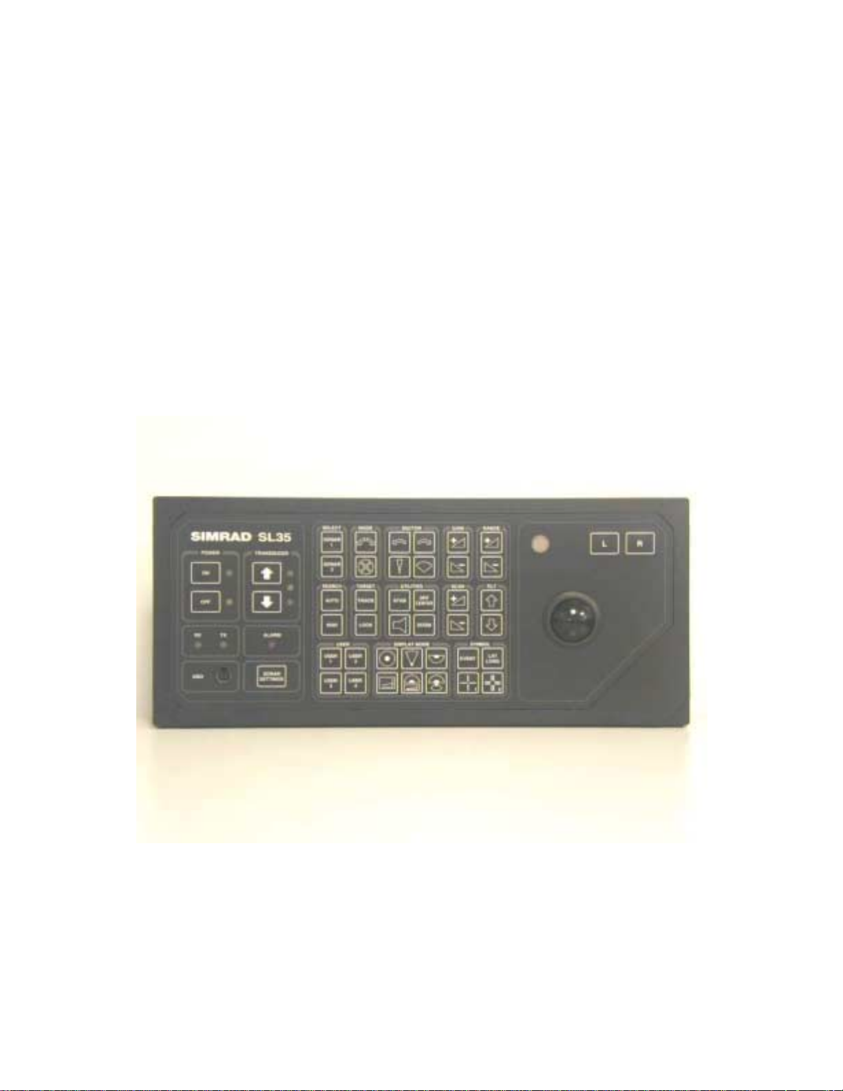
The SL 30/35 Sonar is a modular system. It is operated with ease through a direct
access Control Panel with an integrated mouse.
1.1.1 Equipment Configuration
A complete SL 30/35 Hull Sonar consists of:
• Simrad LCD or VGA Display Monitor. (Optional)
• SL 30/35 Processor Unit.
• SL 30/35 Control Panel and Interface Module.
• SL 30 or 35 Transceiver Assembly.
• SL 30 or 35 Sonar Dome Assembly, Frequency, 90kHz or 160kHz.
• SL 35 Lower and Raise unit, travel, 250 millimeters or 400 millimeters.
• SL 35 Shaft Length: 2.4m, or 3.0m,.
• SL 30/35 Motion Sensor Option.
• SL 30/35 Built-in Internal Audio Speaker, (Optional External Audio Speaker).
• SL 35 Standard Installation Materials
Important notice:
Windows, Windows NT, W indows 2000 and Windows XP are either registered
trademarks or tradem arks of Microsoft Corporat ion in the United States and /or
other countries.
Kongsberg Simrad Mesotech Ltd.
Port Coquitlam, BC - Canada
Page 12
974-25007001/2.0 SL 30/35 Hull Sonar Operators Manual
Page 1.4 System Familia riza tio n
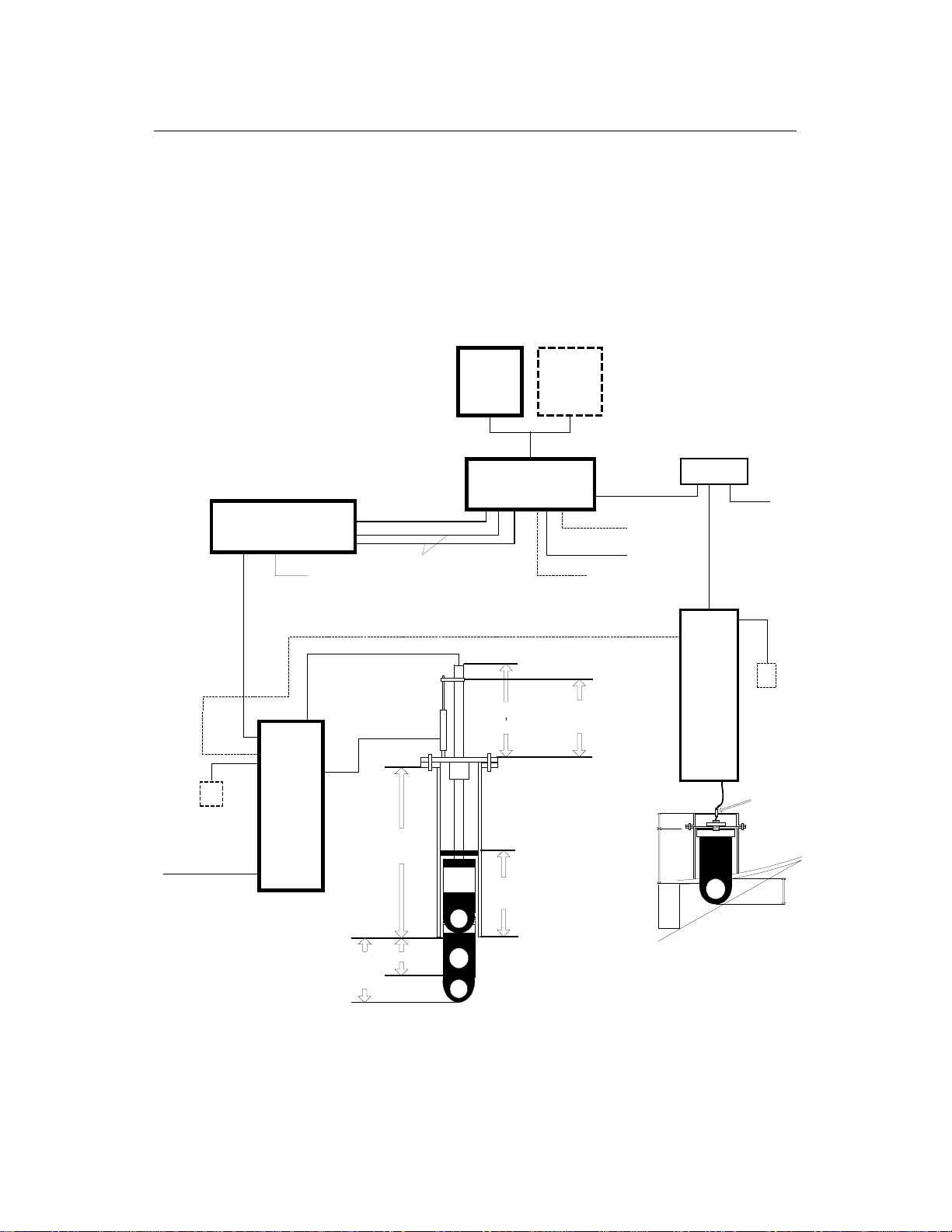
1.1.2 System Diagram
SL 35 Hull Mounted Sonar & SL 30 Catch Sonar
Interconnection System Diagram
(15m / 30m / 50m)
Special Order 100m
(10m)
Optional
Motion Sensor
(2.5m)
Simrad Operating Panel
User Interface
(2.5m)
Power Input
110/220 VAC +/- 10%
RX / TX
Unit
Com 1, RS232 Cable
(2m)
PS 2 KBD/Mouse Cables
(2m) each
( 4.5m / 5.1m )
(1.0m) Input Power
24 VDC
Tank length
(Min. 660 mm)
LCD
Monitor
Processing Unit
Optional
Synchronisation Cable for
Catch Sonar(10m)
1.0m for a 250mm Hoist Unit
1.4m for a 400mm Hoist Unit
Optional
LCD
Monitor
Speaker
Option
Com 2, RS232
(2.5m)
Cable (2m)
External Nav. Unit
Power input
110/220 VAC +/- 10%
254mm
206mm
Interfa ce U n it
Optional
SL 30
(3.5m)
Power input
110/220 VAC +/- 10%
(15m / 30m / 50m)
Special Order 100m
(10m)
RX / TX
Unit
(5m)
Cable Gland
Ship H u ll
Optional
Motion
Sensor
Input Power
24 VDC =/- 10%
250mm
400mm
Travel
Travel
Kongsberg Simrad Mesotech Ltd.
Port Coquitlam, BC - Canada
450 mm
Sonar Dome
90kHz or 160kHz
Keel
Catch Sonar Dome
90kHz or 160kHz
140mm
Page 13

SL 30/35 Hull Sonar Operators Manual 974-25007001/2.
0
5
System Fa milia riza tio n Page 1.
1.1.3 Display
The display monitor for the SL 30/35 Sonar can be either a VGA “CRT” or LCD
Simrad ruggedized monitor, but any commercially available monitor may be used. In
order to have the full benefit of high resolution, you should use a Simrad LCD
Monitor.
1.1.4 Processor Unit
The SL 30/35 Sonar Processing Unit is a rug gedized computer, which can interface
with other auxiliary equipment (Control Panel, Interface Unit, GPS, Echo Sounder
and Trawl Systems, etc.). The processor unit runs on the Microsoft Windows XP
Operating System. The SL 30/35 Sonar System software provides a mechanism f or
the sonar operation. It is operated through the Main Control Panel to enable the
sonar selection, tilt, range, gain and cursors; moving the mouse pointer over the
toolbar will allow the operator to perform certain operations with a simple mouse
click. A flush mounted Control Panel is provided to simplify the operation of the
system.
The rear panel of the processing unit cont ains the connector s f or AC and DC power,
Monitor port, two RS232 Serial Ports, Keyboard, Mouse, Printer, Network LAN and
USB port. The Network LAN port can be used to connect a remote work station, or t o
download data from the processing unit.
Note: A security key (or “dongle”) must be attached to the parallel por t to enable
full operation of the system.
1.1.5 Control Panel and Interface Unit
The SL 30/35 Control Panel contains all necessary control functions for operating
the sonar. As some of the functions are used more frequently than others, the
control buttons are arranged in f unction groups, as Sector T rain, Tilt, Scan Speed,
Range, Display Mode, User Setting and Utilities. The Power ON and OFF butt ons,
the Lower and Raise buttons are also provided for on the SL 35 Hoist Cont r ol.
Note: All sonar operations may also be controlled f rom the int egrated roller ball, or
from an optional remote standard m ouse.
The SL 30/35 Interface Unit is incorporated into the Control Panel assembly,
providing the interface telemetry communication between the Processing Unit and
the Transceiver Unit in the sonar room.
Note that only one signal cable is used for communication between the Interface
Unit and the Transceiver Unit.
Kongsberg Simrad Mesotech Ltd.
Port Coquitlam, BC - Canada
Page 14

974-25007001/2.0 SL 30/35 Hull Sonar Operators Manual
Page 1.6 System Familia riza tio n
1.1.6 Sonar Room Unit
The Transceiver Unit and Lower/Raise Unit are located in the sonar room, mounted
to the tank flange.
The Hull Unit sonar dome is lowered 250 millimeters or 400 millimeters below the
ship’s hull. In case of a power failure the dome assembly will automatically retract
back up into the sonar tank.
Note: The sonar dome can be manually raised by means of a hand pump.
The optional motion sensor for the electronic stabilization of the sonar beams is also
located in the sonar room. A 10 meters int er c onnect ion cable is supplied.
WARNING!!
If the sonar dome hits a larg e object or the bottom, the dome shaft
may be bent, or in the worst case it can be broken off. A broken
sonar dome may cause water leakage at the top of the shaft. To
prevent large leakages in such a case, DO NOT raise the sonar
dome shaft to the upper position. It is t heref or e of gr eat im portance t o
have a good pump and warning system in the sonar room.
DISCLAIMER
This equipment is not certified or approved for navigation and/or safe-
navigation practices and is not to be used for navigation purposes
under any circumstances.
Kongsberg Simrad Mesotech Ltd.
Port Coquitlam, BC - Canada
Page 15

SL 30/35 Hull Sonar Operators Manual 974-25007001/2.
0
7
System Fa milia riza tio n Page 1.
1.2 SL 30/35 TECHNICAL SPECIFICATIONS
• Processing Unit
Operating System: MS Windows XP Professional
40GB Hard Drive
2 SVGA Monitors output
Sound Card
Network LAN Port
4 USB Ports and 2 RS232 Serial Ports
Built-in Audio Speaker
Power input: 115/240VAC, 50/60Hz, +/- 10%, (<5A)
• Data Input/output
NMEA 183 format (RS232)
• Range
Operating Range: 5 meters to 1250 meters
Detection Range: 750m for 90kHz; 450m for the 160kHz Dome
• Tilt
Upward: From 0° to +10°
Downward: From 0° to –90°
• Stabilization
Pitch and Roll: +/- 30°
• Operating Panel
Flush Mounted
Integrated Inter face Unit
Power input: 115/240VAC, 50/60Hz, +/- 10%, (<5A)
Hull Unit
Hoist Unit: Hydraulic Ram
Travel: 250mm or 400mm Stroke
Raising Time: 10 Seconds
Maximum Raising Ship Speed: 15 Knots
• Transceiver Unit
Frequency: 90kHz or 160kHz
Transmit O/P Power: 1.2 kW
Power input: 24/32VDC, +/- 10%, for Hoist Unit Only (<10A)
Sonar Dome Size: 8 inches
• Sonar Dome Unit
Transducer Beam: Cone 8° X 8°, Side Lobe: - 25dB
Installation Trunk: Not DnV approved Trunk. (In process)
• Options:
LCD Monitor
Motion Sensor
External Audio Speaker
UPS Input Power Supply
Kongsberg Simrad Mesotech Ltd.
Port Coquitlam, BC - Canada
Page 16

974-25007001/2.0 SL 30/35 Hull Sonar Operators Manual
Page 1.8 System Familia riza tio n
Kongsberg Simrad Mesotech Ltd.
Port Coquitlam, BC - Canada
Page 17

SL 30/35 Hull Sonar Operators Manual 974-25007001/2.
0
System Description Page 2.1
PART 2
SYSTEM DESCRIPTION
2. SYSTEM DESCRIPTION ................................................................................2.3
2.1 INTRODUCTION .........................................................................................2.3
2.1.1 Basic Principles ....................................................................................2.3
2.1.2 Determining Target Position .................................................................2.3
2.1.3 Forming an Image.................................................................................2.3
2.1.4 Wheelhouse Units Description ..............................................................2.4
2.1.4.1 Display Monitor..............................................................................2.4
2.1.4.2 Processor Unit...............................................................................2.4
2.1.4.3 Control Panel.................................................................................2.5
2.1.4.4 Interface Unit.................................................................................2.5
2.1.4.5 Interconnect Cables.......................................................................2.5
2.1.5 Sonar Room Units Description..............................................................2.5
2.1.5.1 Transceiver Unit.............................................................................2.6
2.1.5.2 Lower and Raise Unit.....................................................................2.6
2.1.5.3 Hull Sonar Dome Unit....................................................................2.6
2.1.5.4 Tank Flange Assembly..................................................................2.6
2.1.5.5 Interconnect Cables.......................................................................2.7
2.1.6 Options.................................................................................................2.7
2.1.6.1 Motion Sensor................................................................................2.7
2.1.6.2 Audio Warning Speaker................................................................. 2.7
2.1.7 Remarks...............................................................................................2.7
2.1.8 Warning................................................................................................2.8
2.1.9 Copyright..............................................................................................2.8
Kongsberg Simrad Mesotech Ltd.
Port Coquitlam, BC - Canada
Page 18

974-25007001/2.0 SL 30/35 Hull Sonar Operators Manual
Page 2.2 System Description
Kongsberg Simrad Mesotech Ltd.
Port Coquitlam, BC - Canada
Page 19

SL 30/35 Hull Sonar Operators Manual 974-25007001/2.
0
3
System Description Page 2.
2. SYSTEM DESCRIPTION
2.1 INTRODUCTION
This section explains the theory of operation of the SL 30/35 Mechanical Scanning
Sonar System.
2.1.1 Basic Principles
• Sound waves travel very efficiently through water.
• A sound pulse can be projected thr ough water in a controlled direction with the
sonar transducer.
• An object in the path of the projected sound pulse will reflect some sound pulse
back toward the sonar transducer.
• The speed of the sound pulse projected through the water can be predicted for
given conditions.
2.1.2 Determining Target Position
The SL 30/35 scanning sonar processor measures the time from the start of the
sound pulse projected through water, to the r eception of the sound pulse ref lected
back to the sonar transducer. The measured time is then convert ed to distance by
using the speed of sound through water.
Since the sound pulse is projected in a known direction, the bearing of the reflected
object is also known. This makes it possible t o locate the object with respect t o the
sonar transducer; the information will be used to plot the position of the reflected
target on a video graphic display monitor.
2.1.3 Forming an Image
The sound pulse projected will be attenuated as it travels through the water from t he
transducer to the target and back. Much of this att enuation is a predictable function
of the total time or the dist ance the sound pulse traveled through water. Increasing
the receiving gain with time can compensate for this decrease in the signal level.
This is done automatically in the sonar with a Time Varying Gain circuit.
Kongsberg Simrad Mesotech Ltd.
Port Coquitlam, BC - Canada
Page 20

974-25007001/2.0 SL 30/35 Hull Sonar Operators Manual
Page 2.4 System Description
After the TVG correction, the absolute levels of the received signals will be
determined by the acoustic response of the ref lect ing target.
The sonar processor system repeatedly measures the TVG corrected target levels
by digitizing a sequence of samples after each sound pulse transmission. Each
sample is then plotted on the video display at the appropriate position according to
its range and bearing. The level of the target strength sample determines the color
used to plot each sample.
The process can be repeated with the transducer pointed in different directions,
forming an image of a large area of the bot t om and displaying it on the video screen.
2.1.4 Wheelhouse Units Description
The following paragraphs will describe the key features of the W heelhouse Units of
the SL 30/35 Hull Sonar.
2.1.4.1 Display Monitor
The display monitor required for the SL 30/35 can be either a VGA “CRT” type or
any commercial LCD monitor. In order t o have the full benefit of high resolution, we
recommend that you select the Simrad rug gedized LCD colour monitor. T he Simrad
colour monitors are available in two sizes, 18” and 20”. The monitor can be desk,
ceiling, or flush mounted into the bridge console.
The Simrad LCD monitor will run on 110/240VAC, 50/60Hz or on 24VDC, +/- 10%.
All mounting hardware is included.
2.1.4.2 Processor Unit
The processor unit is a ruggedized HP “Hewlett Packard” Compaq Processing Unit
designed for use in a marine environment. T he processor unit runs on the Microsoft
Windows XP Prof essional O per ating System.
In the event that you have a problem with the HP computer we recommend that you
contact your Simrad dealer or Agent to assist you in solving the pr oblem.
Hewlett Packard Customer Center can help you solve hardware issues related to HP
products and, if necessary, initiate the appropriate service procedur es. I n the U.S. A.,
telephone support is available 24 hours a day, seven days a week. Elsewhere, in the
world, it is available during normal off ice hour s.
Kongsberg Simrad Mesotech Ltd.
Port Coquitlam, BC - Canada
Page 21

SL 30/35 Hull Sonar Operators Manual 974-25007001/2.
0
5
System Description Page 2.
The HP Customer Care Centers are list ed in the HP Warranty and Support Guide
included with the computer.
Note: If the Hewlett Packard Customer Center can not help you, all warranty and
service requirements are also supplied by the Simrad Dealer s, or Simrad Agents.
2.1.4.3 Control Panel
The SL 30/35 Control Panel contains all of the most frequently used control buttons
required to operate the sonar. The sonar can also be operat ed using the int egrated
roller ball and the on-screen menus and toolbars. Note that the integrat ed roller ball
with its left and right buttons eliminate the need for an external mouse.
All buttons are back-lit f or night operation. An automatic dimmer is incorporated in
the panel, eliminating the need to r aise or lower the intensity of the back illumination.
An external PC keyboard connector is also provided for use during software
maintenance or upgrading.
The SL 30/35 Control Panel is designed for durability and water resistance. The unit
can easily cleaned with a soft cloth dampened with soap and water only.
Details of operation are described in Part 3.
2.1.4.4 Interface Unit
The Interface Unit is incor porated into the Control Panel Assembly. It consists of an
internal 24VDC Power Supply, the RS 232 Interface, the Control Panel keyboard
interface and the Sonar Telem etry Translation Module (TTM) assembly PCB.
2.1.4.5 Interconnect Cables
The interconnection cables are pre-made to specific length. The RS232 and t he PS2
mouse/keyboard cables are 2 meters in leng th. The transceiver cable to t he Control
Panel is available in 4 lengths: 15 meters, 30 meter s, 50 m eter s and special order at
100 meters. The power input cable is 2.5 meters in length.
2.1.5 Sonar Room Units Description
The following paragraphs will explain the key f eatures of the Sonar Room Hull Unit
of the SL 30/35 Sonar.
Kongsberg Simrad Mesotech Ltd.
Port Coquitlam, BC - Canada
Page 22

974-25007001/2.0 SL 30/35 Hull Sonar Operators Manual
Page 2.6 System Description
2.1.5.1 Transceiver Unit
The Transceiver Unit is mounted on the tank flange in a standard installation, but
can also be bulkhead mounted if required. The maximum Sonar Dome cable length
permissible is 5.1 meters depending on the shaft length used during the inst allat ion.
The Transceiver Unit contains the receiver and transmitter PCB assembly and the
lower and raise PCB assembly. A safety power ON/OFF switch is also provided so
power can be shut off when working on the lower and raise assembly. The
transceiver assembly is splash proof to protect t he elect ronics circuits from water.
Note: The safety power ON/ O FF switch is not required for the SL 30 Sonar.
2.1.5.2 Lower and Raise Unit
The SL 35 Lower and Raise Unit is a self-contained hydraulic assembly. Installation
is simple and only requires the fitting of 2 clevis pins and connection of the power
cable from the Transceiver Unit.
.
The travel length is available in two sizes, 250 millimeters and 400 millimeters
depending on the installation requirement.
2.1.5.3 Hull Sonar Dome Unit
The Hull Sonar Dome unit is available in two frequencies, 90kHz and 160 kHz. The
cable length is available in 4.5 meters for a 2.4 or 3 meter shaft and 5.1 meters with
a 3.6 meters optional shaft. Special attention must be paid to matching cable and
shaft lengths when ordering the system.
Note: The SL 30 Catch Sonar Dome comes with a standard 5 meter cable length.
2.1.5.4 Tank Flange Assembly
The SL 35 Tank Flange Assembly main body is cast in ASTM A536, 60-40-18
Ductile Iron. Special mounting pads and a guide are incorporated into the flange.
The shaft bearing is made of SEA 660 Bearing Bronze. Special attent ion was given
during the design to the seal and shaft packing in order to prevent water leakage
into the sonar room. A zinc anode is also installed on the tank flange, to reduce
electrolysis.
Note: The Tank Flange Assembly is not required for the SL 30 Dome; all flanges are
serial-numbered.
Kongsberg Simrad Mesotech Ltd.
Port Coquitlam, BC - Canada
Page 23

SL 30/35 Hull Sonar Operators Manual 974-25007001/2.
0
7
System Description Page 2.
2.1.5.5 Interconnect Cables
The only interconnection cable supplied with the transceiver is the 2.5 meters power
input cable. All other cables are supplied with the other units.
2.1.6 Options
The following paragraph explains the key features of the Optional Units of the SL
30/35 Hull Sonar.
2.1.6.1 Motion Sensor
The Motion Sensor unit will compensate +/- 30 degrees for the pitch and r oll of the
fishing vessel. A 10 meter interconnect ion cable and mounting hardware is supplied
when you purchase the Sensor.
2.1.6.2 Audio Warning Speaker
The Audio Warning Speaker is built into the Processor Unit. If you require an
external audio speaker, You may purchase it locally. The audio speak er connects to
the rear of the Processing Unit
2.1.7 Remarks
Further information about the SL 30/35 system may be found in the following
manual.
This Operator and Installation Manual is intended for the design and installation
engineers at the shipyard. On completion of the installation, this manual must be
kept on the vessel for ref er ence pur poses dur ing system maintenance.
Kongsberg Simrad Mesotech Ltd. mak es every effort to ensure t hat the informat ion
contained within this manual is correct. However, our products are continuously
being improved and updated, so we cannot assume liability for any errors that m ay
occur.
Note: All specifications are subject to change wit hout notice.
Kongsberg Simrad Mesotech Ltd.
Port Coquitlam, BC - Canada
Page 24

974-25007001/2.0 SL 30/35 Hull Sonar Operators Manual
Page 2.8 System Description
2.1.8 Warning
The product to which this manual applies must only be used for the purpose for
which is it was designed. Improper use or maintenance may cause damage to the
product or injury to personnel. The user must be familiar with the contents of the
appropriate manual before att em pt ing to operate or work on the product.
Kongsberg Simrad Mesotech Ltd. disclaims any responsibility for damage or injury
cause by improper installation, use or maintenance of t he pr oduct.
2.1.9 Copyright
The information contained within this document remains the sole property of
Kongsberg Simrad Mesotech Ltd. No part of this document may be copied or
reproduced in any form or by any means, and the information contained within is not
to be communicated to a third party, without the pr ior written consent of Kongsberg
Simrad Mesotech Ltd.
DISCLAIMER
This equipment is not certified or approved for navigation and/or safe-navigation
practices and is not to be used for navigation purposes under any circum st ances.
Kongsberg Simrad Mesotech Ltd.
Port Coquitlam, BC - Canada
Page 25

SL 30/35 Hull Sonar Operators Manual 974-25007001/2.
0
Control Panel Page 3.1
PART 3
SL 30/35 CONTROL PANEL
3. SL 30/35 CONTROL PANEL OPERATION.....................................................3.3
3.1 INTRODUCTION .........................................................................................3.3
3.2 CONTROL PANEL.......................................................................................3.3
3.3 MAIN POWER SWITCH.............................................................................. 3.4
3.3.1 Power ON/OFF Buttons........................................................................3.4
3.3.2 Sonar Dome Transducer Buttons..........................................................3.5
3.3.3 Sonar Settings Button...........................................................................3.5
3.3.4 Roller Ball and Mouse Buttons.............................................................. 3.6
3.3.5 Sonar Selection Buttons........................................................................3.6
3.3.6 Range Buttons......................................................................................3.7
3.3.7 Gain Buttons.........................................................................................3.7
3.3.8 Scan Buttons ........................................................................................3.8
3.3.9 Tilt Buttons............................................................................................3.9
3.3.10 Sector Control Buttons ......................................................................3.9
3.3.10.1 Move Sector Left Button ..............................................................3.10
3.3.10.2 Move Sector Right Button............................................................3.10
3.3.10.3 Narrow Sector Button...................................................................3.10
3.3.10.4 Widen Sector Button....................................................................3.10
3.3.11 Sector Aiming Mode Buttons...........................................................3.11
3.3.12 Utilities Buttons................................................................................3.12
3.3.12.1 Off Center Button.........................................................................3.12
3.3.12.2 Zoom Button................................................................................3.12
3.3.12.3 Stabilize Button............................................................................3.13
3.3.12.4 Speaker Button............................................................................3.13
3.3.13 Target Track and Lock Buttons.......................................................3.13
3.3.14 Auto and Manual Search Buttons....................................................3.14
3.3.15 Symbol Buttons...............................................................................3.15
3.3.15.1 Latitude / Longitude Button..........................................................3.15
3.3.15.2 Event Mark Button.......................................................................3.15
3.3.15.3 Cursor Buttons.............................................................................3.16
3.3.16 User Buttons ...................................................................................3.17
3.3.17 Display Mode Buttons......................................................................3.17
3.3.17.1 Horizontal Display Mode Button...................................................3.18
3.3.17.2 Bow Up Display Mode Button.......................................................3.18
3.3.17.3 Vertical Fan Mode Button.............................................................3.18
Kongsberg Simrad Mesotech Ltd.
Port Coquitlam, BC - Canada
Page 26

974-25007001/2.0 SL 30/35 Hull Sonar Operators Manual
Page 3.2 Control Panel
3.3.17.4 Sounder Mode Button..................................................................3.19
3.3.17.5 Horizontal Mode with History Mode button...................................3.19
3.3.17.6 Horizontal Mode with Real Time Vertical Strata Mode Button......3.19
3.3.18 RX and TX Indicator LED................................................................3.20
3.3.19 Alarm Indicator LED........................................................................3.20
3.3.20 Keyboard (KBD) External Plug-in....................................................3.20
3.3.21 Panel Light Dimmer Sensor.............................................................3.21
3.3.22 Menu Description ............................................................................3.21
Kongsberg Simrad Mesotech Ltd.
Port Coquitlam, BC - Canada
Page 27
SL 30/35 Hull Sonar Operators Manual 974-25007001/2.
0
3
Control Panel Page 3.
3. SL 30/35 CONTROL PANEL OPERATION
3.1 INTRODUCTION
The SL 30/35 Sonar uses a Control Panel for the most frequently needed
adjustments and a software menu system f or less frequently needed controls. This
chapter describes how to use the Control Panel to operate the sonar .
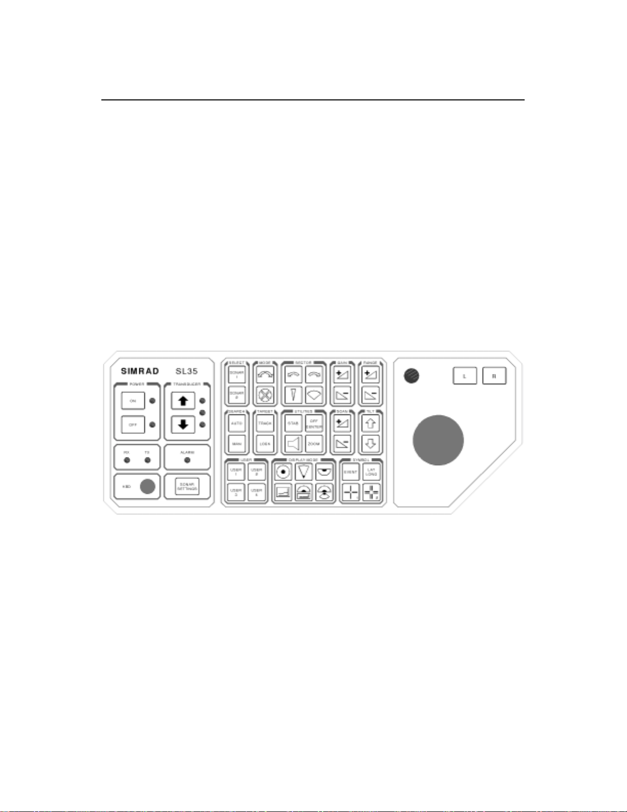
3.2 CONTROL PANEL
A thorough understanding of the system functions and controls is necessary to
optimize the overall performance. Sonar condit ions vary, sometimes drastically, and
it is not possible to identify proper sett ings that will provide the best sonar image at
all times.
Careful study of the information in this manual is highly recommended, preferably
while exploring the sonar’s various functions. System operation is a dynamic activity
requiring regular adjustment and fine-tuning to achieve the best possible results
under varying environmental conditions.
The Control Panel Buttons are described in the following paragraphs.
Kongsberg Simrad Mesotech Ltd.
Port Coquitlam, BC - Canada
Page 28
974-25007001/2.0 SL 30/35 Hull Sonar Operators Manual
Page 3.4 Control Panel
3.3 MAIN POWER SWITCH
The Main Power Switch controls power to the Interface Unit, t he Sonar Transceiver
Unit, the hull Transducer Dome Assembly and the hoisting and lowering unit of the
hull transducer dome.
Note: When the SL 30/35 System is supplied with a HP/PC Processing Unit, power
must be turned on separately.
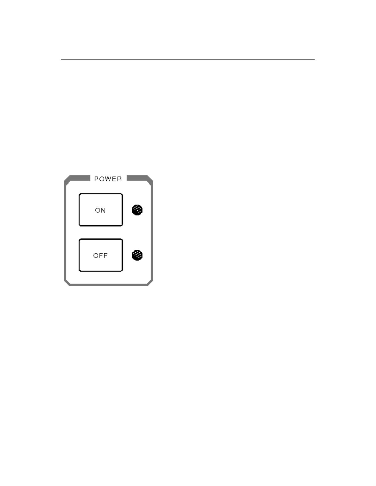
3.3.1 Power ON/OFF Buttons
Press the Power ON button for approximately two seconds to power up the sonar.
The adjacent green LED will light up and remain illuminated indicating that power
has been supplied to the sonar and the system is ready for operat ion.
Press the Power OFF button to remove the power to the sonar. The adjacent red
LED will light up and remain illuminated indicating that power has been rem o ved.
Note: The Hull sonar dome transducer unit will automatically retract into the tank if
Power is turned OFF, or if a loss of Power is detected. The green LED adjacent to
the UP Transducer Arrow button will light, indicating that the hull sonar dome
transducer is retracted into t he t ank and will remain illuminated.
Kongsberg Simrad Mesotech Ltd.
Port Coquitlam, BC - Canada
Page 29
SL 30/35 Hull Sonar Operators Manual 974-25007001/2.
0
5
Control Panel Page 3.
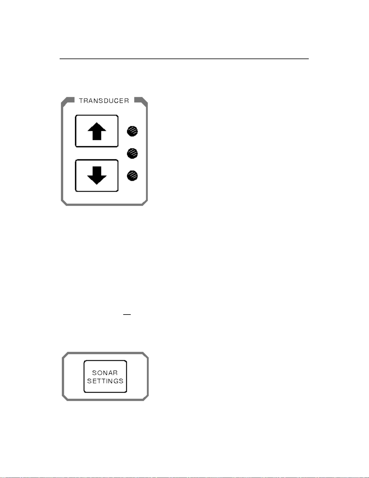
3.3.2 Sonar Dome Transducer Buttons
Press the UP Transducer Arrow button to raise the sonar dome to its upper position.
The middle yellow LED will blink while the sonar dome is being raised. The upper
green LED will light and remain illuminated when the sonar dome has reached the
full up position and is housed safely inside the hull of t he vessel.
Press the DOWN Transducer Arrow button to lower the sonar dome into its down
position. The middle yellow LED will blink while the sonar dome is lowering. The
lower green LED will light and remain illuminated when the sonar dome has reached
the full down position.
When the Power is tur ned off or if a power failure is detect ed, the sonar dome will
automatically retract safely inside the hull of the vessel and the upper gr een LED will
remain illuminated. If no Transducer LED’s are illuminated while the power has been
turned OFF, this indicates that the sonar dome has not been retr acted safely into the
hull of the vessel.
3.3.3 Sonar Settings Button
Press the Sonar Settings Button to display or hide the Header Menu at the top of the
display. Use the roller ball to move the cursor over one of the Header Menu and click
Kongsberg Simrad Mesotech Ltd.
Port Coquitlam, BC - Canada
Page 30
974-25007001/2.0 SL 30/35 Hull Sonar Operators Manual
Page 3.6 Control Panel
the “L” button (left m ouse button). The Header Menu allows quick access to several
features that do not have a dedicated icon or but t on on the Control Panel.
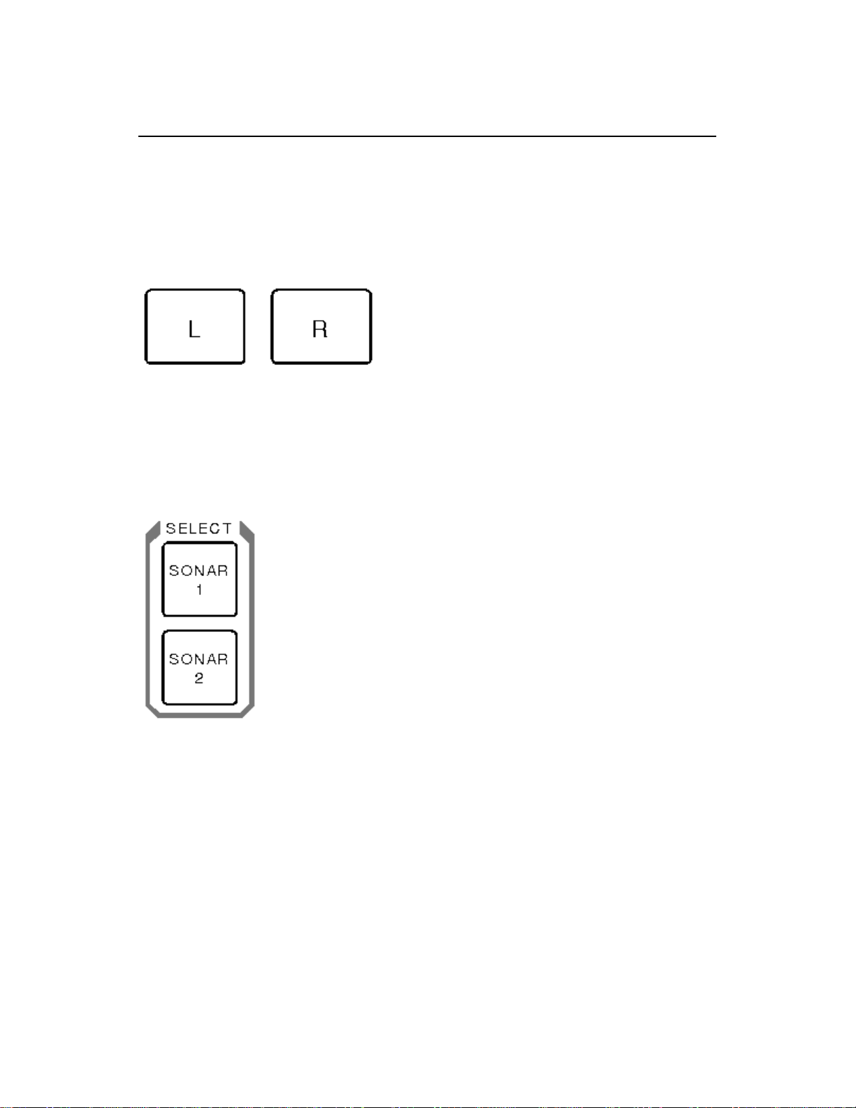
3.3.4 Roller Ball and Mouse Buttons
The Roller Ball (Trackball), “L” (left m ouse button) and the “R” (r ight mouse button)
allow you to move the mouse cursor and control the system by means of the menu
system and Tool Bar system on the display.
3.3.5 Sonar Selection Buttons
You do not need to use the Sonar Selection buttons if you only have one sonar hull
unit. These buttons are provided to allow you to select the active sonar when two
sonar hull units have been installed; for example: one SL 35, 90 kHz sonar and one
SL 35, 160 kHz sonar.
Press the Sonar 1 button or the Sonar 2 button to select the sonar you want to
control.
Note: If you only have a single sonar installed on the vessel, sonar 1 will be
automatically selected. If a second sonar is installed on the vessel, sonar 1 will be
automatically selected during the power-up.
Kongsberg Simrad Mesotech Ltd.
Port Coquitlam, BC - Canada
Page 31

SL 30/35 Hull Sonar Operators Manual 974-25007001/2.
0
7
Control Panel Page 3.
3.3.6 Range Buttons
The Range Buttons control the Hor izontal and the Vertical range of the sonar. Use
the roller ball and move the mouse cursor over the sonar display you want to contr ol
and click on the “L” Left but t on.
Press the Range “+” or “-“ buttons to increase or decrease the operating range of
the sonar.
Note: You also can control the sonar r ange by using the roller ball and moving the
mouse cursor over the display window control panel. Click on the Up or Down arrow
pointer to increase or decrease the range.
See Part 4 for Pop-Up Control Panel descr iption and operation.
3.3.7 Gain Buttons
The Gain Buttons can control the gain settings of the selected sonar.
• Use the roller ball and m ove the mouse cursor over the sonar display you want
to control then click the “L” Left button.
Kongsberg Simrad Mesotech Ltd.
Port Coquitlam, BC - Canada
Page 32

974-25007001/2.0 SL 30/35 Hull Sonar Operators Manual
Page 3.8 Control Panel
• Press the Gain “+” or “-“ buttons to increase or decrease the operating gain of
the sonar.
• You also can control the sonar g ain by using the roller ball to move t he mouse
cursor over the display window control panel to adjust the gain slider level.
See Part 4 for Pop-Up Control Panel descr iption and operation.
3.3.8 Scan Buttons
The Scan Buttons control the Horizontal and the Vertical scanning speed of the
selected sonar.
• Use the roller ball to move the mouse cursor over the sonar display you want to
control then click the “L” Lef t but ton.
• Press the Scan “+” or “-“ buttons to increase or decrease the operating
scanning speed of the sonar.
• You also can control the sonar scanning speed by using the roller ball to move
the mouse cursor over the display window control panel scan speed. Click on
the Up or Down arrow pointer to increase or decrease the scanning speed.
See Part 4 for Pop-Up Control Panel descr iption and operation.
Kongsberg Simrad Mesotech Ltd.
Port Coquitlam, BC - Canada
Page 33

SL 30/35 Hull Sonar Operators Manual 974-25007001/2.
0
9
Control Panel Page 3.
3.3.9 Tilt Buttons
The Tilt Up and Tilt Down arrow buttons contr ol the tilt ang le of the transducer for a
selected sonar.
• Positive tilt from 0 degrees to +10 degrees (upward)
• Negative tilt from 0 degr ees to -90 degrees (downward)
• You also can control the sonar transducer tilt angle by using the roller ball to
move the mouse cursor over the display window control panel tilt angle and click
on the Up or Down arrow pointer to increase or decrease the tilt
See Part 4 for Pop-Up Control Panel descr iption and operation.
3.3.10 Sector Control Buttons
The Sector Control buttons are used to control the direction (Train Heading) and
width of the sector to be scanned by the sonar.
Kongsberg Simrad Mesotech Ltd.
Port Coquitlam, BC - Canada
Page 34

974-25007001/2.0 SL 30/35 Hull Sonar Operators Manual
Page 3.10 Control Panel
3.3.10.1 Move Sector Left Button
Press the Move Sector Left button to re-center the scanning sector (T rain Heading)
more to the left.
3.3.10.2 Move Sector Right Button
Press the Move Sector Right button to re-center the scanning sect or (T rain heading)
more to the right.
3.3.10.3 Narrow Sector Button
Press the Narrow Sector button to reduce the width of the scanned sector. The
minimum sector width is 8 degrees.
3.3.10.4 Widen Sector Button
Press the Widen Sect or but ton to increase the width of the scanned sector.
• The maximum width setting will provide a full 360 degrees horizontal display.
• You also can control the sonar sector width opening by using the roller ball to
Kongsberg Simrad Mesotech Ltd.
Port Coquitlam, BC - Canada
Page 35

SL 30/35 Hull Sonar Operators Manual 974-25007001/2.
0
Control Panel Page 3.11
move the mouse cursor over the display window control panel sector width and
click on the Up or Down arrow pointer to increase or decrease the sector width.
See Part 4 for Pop-Up Control Panel descr iption and operation.
3.3.11 Sector Aiming Mode Buttons
Press the Mode double arrow button to reverse the scan train direction (same as
Scan Reverse mode).
Press the Mode four-quadrant button to change the sector train heading by 90
degrees. Press the four-quadrant button a second time to change the sector train
heading by another 90 degrees.
For example: If your center of sector train heading is at 0 degrees, it will change to
90 degrees, next to 180 degrees and then to 270 deg rees. The next time you pr ess
the quadrant button it will return to 180 degrees and next t o 90 degrees and back t o
0 degrees.
Note: This feature allows quick adjustm ent of the sector heading.
Kongsberg Simrad Mesotech Ltd.
Port Coquitlam, BC - Canada
Page 36

974-25007001/2.0 SL 30/35 Hull Sonar Operators Manual
Page 3.12 Control Panel
3.3.12 Utilities Buttons
3.3.12.1 Off Center Button
Press the Off Cent er but ton to move the Own vessel’s center of origin.
• Press the Off Center button, a red marker will be displayed on the screen
• Move the mouse red marker cursor t o the position that you want to extend the
view and left click the mouse button; the r ange will be doubled in that direction
• Press the Off Center button a second time to return the Own vessel center of
origin back to its original position.
3.3.12.2 Zoom Button
Press the Zoom Button to magnif y an area of the display around the mouse cursor.
Press again to change the magnificat ion. The Zoom button will select X1, X2, and
X4 magnification.
Kongsberg Simrad Mesotech Ltd.
Port Coquitlam, BC - Canada
Page 37

SL 30/35 Hull Sonar Operators Manual 974-25007001/2.
0
3
Control Panel Page 3.1
3.3.12.3 Stabilize Button
Press the Stabilize (STAB) Button to turn ON automatic transducer pitch and roll
stabilization. Press the STAB button a second tim e t o t ur n st abilization O FF.
3.3.12.4 Speaker Button
Press the Speaker Mute button to activate or deactivate the audio monitor of fish
and/or bottom detection. T his option is used as an audio alert t o inform the oper ator
that detection has been made.
3.3.13 Target Track and Lock Buttons
Press the Target Tr ack button to activate the tracking of the selected target. To track
a target, place the mouse cursor over the desired location and press the Target
Track button. A circ le will appear on the display and its position will be automatically
tracked by the system using the strongest fish echo centered in the “window”
represented by two lines on the audio line. The window’s size may be selected in the
track Window menu.
Kongsberg Simrad Mesotech Ltd.
Port Coquitlam, BC - Canada
Page 38

974-25007001/2.0 SL 30/35 Hull Sonar Operators Manual
Page 3.14 Control Panel
The vector originating from the target’s center indicates target course and speed.
The length of the vector increases relative to the target’s speed. One knot is
represented by a small mark on the vector. A course line can also be displayed
showing the target’s track.
When the Aut o Search is activated during the Target Track mode, t he tilt angle will
automatically follow the strongest f ish echo. The upper and lower tilt angle limit s can
be used to prevent tracking surf ace or bottom echoes The target tracking symbols
and data are displayed in a different colour.
Note: The Target Track and Lock option are not available at this time on the SL
35 Sonar and will be available in the near future.
3.3.14 Auto and Manual Search Buttons
Press the Auto Search button to activate the selected tilt angle upper and lower
limits, with the tilt step size that was pre-set by the system operator.
• In Auto Search, the transducer will automatically change tilt angle after each
complete scan search is performed. Af ter each scan search the transducer will
tilt up or down within the pre-set limits.
• Press the Manual Search button to allow the transducer to be tilted by pressing
the Tilt up or Tilt down buttons.
• The search limits can be changed by using the roller ball and moving the mouse
cursor on the Sonar Icon located on the Tool Bar and clicking on the “L” left
button.
See Part 4 for the Tool Bar Icon and Sonar setting description and operation.
Kongsberg Simrad Mesotech Ltd.
Port Coquitlam, BC - Canada
Page 39

SL 30/35 Hull Sonar Operators Manual 974-25007001/2.
0
5
Control Panel Page 3.1
3.3.15 Symbol Buttons
The Symbol Buttons are used to place special symbols on the display.
3.3.15.1 Latitude / Longitude Button
This button allows you to mark the latitude and longitude of a target on the display.
Use the roller ball to move the mouse cursor over a specific location on the sonar
image then press the LAT/LO NG but ton to display a Lat/Long marker with a window
indicating the latitude and longitude of the selected target. Pr ess t he LAT/LONG
button a second time to remove the marker and window.
3.3.15.2 Event Mark Button
You can place up to four Event marker symbols anywhere on the display screen as
follows:
• Use the roller ball to move the mouse cursor to the desired location on the sonar
image.
• Press the Event button to automatically display an event marker 1. If you move
the cursor and press the Event button a second time, you can display a second
Event marker 2.
Kongsberg Simrad Mesotech Ltd.
Port Coquitlam, BC - Canada
Page 40

974-25007001/2.0 SL 30/35 Hull Sonar Operators Manual
Page 3.16 Control Panel
• To delete an existing event marker, use the roller ball to move the m ouse cursor
over it and press the Event button again.
3.3.15.3 Cursor Buttons
Two special reference cursors are available to be placed anywhere on the sonar
image. The positions of t hese cursor s and the rang e and bear ing between t hem are
shown in a Cursor Gauge window.
To place Cursor 1 on the display:
• Use the roller ball to move the mouse cursor to t he desir ed location on the image
• Press the Cursor 1 button to automatically display the Cursor Gauge Window
and the Cursor 1 marker.
Use the same procedure with the Cursor 2 button to place t he Cur sor 2 marker.
To move Cursor 1 to a new position:
• Use the roller ball to move the mouse cursor over the Curs or 1 m arker
• Press and hold down the Left “L” button and drag t he cur s or t o a new position
Use the same procedure with the Cursor 2 button to m ove the Curs or 2 m ar ker.
To delete a cursor:
• Move the mouse cursor over the W iper icon locat ed on the Tool Bar and
click the Left “L” but t on
• Then move the Wiper over the cursor t o be deleted and click the Left “L” mouse
button
To hide the Cursor Gauge Window:
• Move the mouse cursor over the X in the upper right hand corner and click the
Left “L” button
Kongsberg Simrad Mesotech Ltd.
Port Coquitlam, BC - Canada
Page 41

SL 30/35 Hull Sonar Operators Manual 974-25007001/2.
0
7
Control Panel Page 3.1
3.3.16 User Buttons
The User Buttons selection can be perfor med using the menu or the main contr ol
panel, which contains four operator selectable set-ups.
Frequently used tasks specific to a par ticular phase of the fishing operation can be
pre-set in the User 1, 2, 3 or 4.
For example “User 1” may be used for the search phase, “User 2” f or the evaluation
phase, “User 3” for the catch phase and “ User 4” for the Dual operation.
3.3.17 Display Mode Buttons
The Display Mode Buttons are used to set the format of the sonar display.
Kongsberg Simrad Mesotech Ltd.
Port Coquitlam, BC - Canada
Page 42

974-25007001/2.0 SL 30/35 Hull Sonar Operators Manual
Page 3.18 Control Panel
3.3.17.1 Horizontal Display Mode Button
Press the Horizontal Display Mode button to provide a 360 degree plane of coverage
for general search.
See Part 5 for Setting Select ion.
3.3.17.2 Bow Up Display Mode Button
Press the Bow Up Display Mode button to provide a sector up plane coverage of 180
degrees, with the center of origin at the bottom of the scr een. You can change the
scanned sector width by using the Sector Width button.
See Part 5 for Setting Select ion.
3.3.17.3 Vertical Fan Mode Button
Press the Vertical Fan Display Mode button to provide a vertical section of the
underwater bottom conditions on the entire screen. T he maximum coverage is 180
degrees. You can change the scanned sector width and heading by using the Sector
Width and Heading but tons.
See Part 5 for Setting Select ion.
Kongsberg Simrad Mesotech Ltd.
Port Coquitlam, BC - Canada
Page 43

SL 30/35 Hull Sonar Operators Manual 974-25007001/2.
0
9
Control Panel Page 3.1
3.3.17.4 Sounder Mode Button
Press the Sounder Display Mode button to provide a fixed echo beam displaying f ish
echoes below and/or around the vessel.
See Part 5 for Setting Select ion.
3.3.17.5 Horizontal Mode wi t h Hi st ory Mode button
Press the Horizontal with History Display Mode button to provide a 180 degrees
Horizontal Sector main display with the history displayed in a second window. This
enables the operator to observe the history of fish movement and distribution
equivalent to approximately four full 360 degrees scans. It is also useful for detecting
bottom fish and reefs.
Note: The History Window cannot be adjust ed.
See Part 5 for Setting Select ion.
3.3.17.6 Horizontal Mode wi t h Real Time Vertical Strata Mode Button
Press the Horizontal / Vertical Fan Strata Display Mode button to provide a 180
degree Horizontal Sector main display, with the Real Time Vertical Fan displayed in
a second window. This enables the operator to observe the history of fish
movement and distribution in real time. T he Vertical Fan Strata Mode also provides
in real time the range, depth and heading of the fish echoes.
Note: The Vertical Fan Strata Window cannot be adjusted.
Kongsberg Simrad Mesotech Ltd.
Port Coquitlam, BC - Canada
Page 44

974-25007001/2.0 SL 30/35 Hull Sonar Operators Manual
Page 3.20 Control Panel
See Part 5 for Setting Select ion.
3.3.18 RX and TX Indicator LED
Receiver “RX” and Transmitter “TX” LEDs are provided to indicate that
communication is functioning between the Processing Unit and the Transceiver Unit.
If the LEDs do not blink, a com m unication problem has occurred.
3.3.19 Alarm Indicator LED
The Alarm LED provides a visual indication that the processor unit has f ailed or a
communication error has occured.
3.3.20 Keyboard (KBD) External Plug-in
An external Keyboard (KBD) is provided for software maint enance support.
Kongsberg Simrad Mesotech Ltd.
Port Coquitlam, BC - Canada
Page 45

SL 30/35 Hull Sonar Operators Manual 974-25007001/2.
0
Control Panel Page 3.21
3.3.21 Panel Light Dimmer Sensor
A Panel Light Dimmer Sensor is provided to automatically increase or decrease
brightness of the lig ht and to turn it off completely in daylight.
3.3.22 Menu Description
The SL 30/35 Menu Description and Operation is described in Part 4 of this manual.
DISCLAIMER
This equipment is not certified or approved for navigation and/or safe-navigation
practices and is not to be used for navigation purposes under any circum st ances.
Kongsberg Simrad Mesotech Ltd.
Port Coquitlam, BC - Canada
Page 46

974-25007001/2.0 SL 30/35 Hull Sonar Operators Manual
Page 3.22 Control Panel
Kongsberg Simrad Mesotech Ltd.
Port Coquitlam, BC - Canada
Page 47

SL 30/35 Hull Sonar Operators Manual 974-25007001/2.
0
Menu and Software Description Page 4.1
PART 4
MENU AND SOFTWARE DESCRIPTION
4. MENU AND SOFTWARE DESCRIPTION.......................................................4.5
4.1 INTRODUCTIONS.......................................................................................4.5
4.2 ASSUMPTIONS...........................................................................................4.5
4.3 SCOPE OF THIS MANUAL..........................................................................4.5
4.4 SOFTWARE INSTALLATION......................................................................4.6
4.5 HARDWARE SECURITY KEY.....................................................................4.6
4.6 MAIN CONTROL PANEL.............................................................................4.7
4.7 THE TOOLBARS.........................................................................................4.8
4.8 SONAR TOOLBAR......................................................................................4.8
4.9 MARKER TOOLBAR..................................................................................4.10
4.10THE STATUS BAR....................................................................................4.10
4.11REFERENCE CURSORS ..........................................................................4.11
4.12KEY SETTINGS PANEL............................................................................4.11
4.13HO W TO CONNECT AND SETUP A HEAD (FIRST TIME OPERATION). 4.12
4.14HOW TO USE THE SONAR (SOME RULES OF THUMB)........................4.12
4.15HOW TO RESET TO THE FACTORY DEFAULT SETTINGS...................4.13
4.16HOW TO USE THE BASIC SONAR CONTROLS......................................4.13
4.17HOW TO SELECT UNITS OF MEASURE (FEET, YARDS, METERS)......4.14
4.18HOW TO SET OR ESTIMATE THE VELOCITY OF SOUND.....................4.14
4.19HOW TO INTERPRET THE SONAR IMAGE.............................................4.15
4.19.1 The Color Palette............................................................................4.15
4.19.2 Bright Spots.....................................................................................4.15
4.19.3 Dark Spots ......................................................................................4.15
4.19.4 Shadows .........................................................................................4.16
4.19.5 Noise and Interference....................................................................4.16
4.19.6 Masking Effects...............................................................................4.16
4.19.7 Range Scale and Target Size..........................................................4.17
4.19.8 Mirroring Effects..............................................................................4.17
4.20HOW TO GET THE HIGHEST RESOLUTION IMAGE..............................4.17
4.21HOW TO GET THE FASTEST UPDATE RATE......................................... 4.17
4.22HOW TO USE THE MULTIPLE USER FEATURE.....................................4.18
4.22.1 To create a new user name and configuration:................................ 4.18
4.22.2 To select a different user configuration: ..........................................4.18
4.23HOW TO RECORD AND PLAYBACK SONAR DATA ...............................4.18
4.23.1 To record sonar data:......................................................................4.18
Kongsberg Simrad Mesotech Ltd.
Port Coquitlam, BC - Canada
Page 48

974-25007001/2.0 SL 30/35 Hull Sonar Operators Manual
Page 4.2 Menu and Software Description
4.23.2 To playback sonar data:..................................................................4.19
4.24HOW TO CUSTOMIZE THE HEAD SETTINGS DISPLAY ........................4.19
4.25HOW TO CREATE A CUSTOM GAUGE WINDOW ..................................4.20
4.26HOW TO SHOW A CLOSED OR HIDDEN GAUGE WINDOW .................4.20
4.27ABOUT NETWORKING.............................................................................4.20
4.28STAND ALONE MODE..............................................................................4.21
4.28.1 Server Mode....................................................................................4.21
4.28.2 Passive Client Mode........................................................................4.21
4.28.3 Active Client Mode...........................................................................4.21
4.29HO W TO SETUP A NETW ORK CONNECTION (WINDOWS NT/2000) ...4.22
4.30HOW TO SETUP THIS SONAR AS THE SERVER...................................4.23
4.31HOW TO SETUP THIS SONAR AS A PASSIVE CLIENT..........................4.23
4.32HOW TO SETUP THIS SONAR AS THE ACTIVE CLIENT.......................4.24
4.33HOW TO SETUP THIS SONAR FOR STAND-ALONE OPERATION........4.24
4.34HOW TO EXPORT DATA TO A FILE........................................................4.24
4.35HOW TO EXPORT DATA TO A SERIAL PORT........................................4.25
4.36HOW TO SETUP FOR AND DISPLAY GPS DATA...................................4.26
4.36.1 To setup the system to accept position data from a GPS receiver: .4.26
4.36.2 To setup the system to display position data fr om a GPS receiver:. 4. 26
4.37HOW TO SETUP FOR AND DISPLAY COMPASS DATA.........................4.26
4.38HOW TO SETUP FOR AND DISPLAY OTHER NMEA DATA...................4.27
4.39HOW TO SETUP USER DEFINED SENSORS.........................................4.28
4.40THE FILE MENU........................................................................................4.29
4.41THE VIEW MENU......................................................................................4.29
4.42CONTROL PANEL MENU.........................................................................4.30
4.43DISPLAY MENU........................................................................................4.31
4.44MESSAGE LOG MENU.............................................................................4.31
4.45THE CONFIGURATION MENU.................................................................4.32
4.46USERS MENU...........................................................................................4.33
4.47THE OPERATIONS MENU........................................................................4.33
4.48PLAYBACK DATA MENU..........................................................................4.34
4.49THE TARGETS MENU ..............................................................................4.35
4.50NETWORK MENU.....................................................................................4.36
4.51THE WINDOW MENU...............................................................................4.38
4.52THE HELP MENU......................................................................................4.39
4.53POPUP MENUS ........................................................................................4.39
4.54HEAD SETTINGS GAUGE WINDOW .......................................................4.40
4.55ABOUT DIALOG BOX ...............................................................................4.41
4.56ADD USERS AND GROUPS (WINDOW S NT/2000 OR XP).....................4.42
4.57CLIENT LIST DIALOG BOX.......................................................................4.42
4.58CONFIRM EXIT DIALOG BOX.................................................................. 4.43
4.59DISPLAY SETTINGS DIALOG BOX..........................................................4.44
4.59.1 Display Settings: Colors ..................................................................4.44
4.59.1.1 Palette Styles...............................................................................4.46
4.59.1.2 Primary Overlay Colors buttons...................................................4.46
4.59.1.3 The Palette Threshold..................................................................4.46
Kongsberg Simrad Mesotech Ltd.
Port Coquitlam, BC - Canada
Page 49

SL 30/35 Hull Sonar Operators Manual 974-25007001/2.
0
3
Menu and Software Description Page 4.
4.59.2 Display Settings: Controls ...............................................................4.46
4.59.2.1 Sector View..................................................................................4.47
4.59.2.2 Display Gain................................................................................4.47
4.59.2.3 Rx Gain Type...............................................................................4.47
4.59.2.4 Scan marker................................................................................4.47
4.59.2.5 Grid control.................................................................................. 4.47
4.59.2.6 Timer ...........................................................................................4.47
4.59.2.7 Scroll Speed ................................................................................4.48
4.59.3 Distributed COM Configuration Properties Applications................... 4.48
4.59.4 Distributed COM Configuration Properties Default Properties .........4.48
4.59.5 Export Data File Selection Dialog Box.............................................4.48
4.59.5.1 Export Dialog Box........................................................................4.48
4.59.5.2 Export: Export Selection ..............................................................4.49
4.59.5.3 Automatic File..............................................................................4.49
4.59.5.4 Export: Ports Configuration..........................................................4.50
4.59.6 Head Settings Dialog Box................................................................4.51
4.59.6.1 Head Settings: Scan....................................................................4.52
4.59.6.2 Head Settings: Transmit ..............................................................4.53
4.59.6.3 Head Settings: Info ......................................................................4.55
4.59.6.4 Head Settings: TVG.....................................................................4.57
4.59.7 Machine Name Dialog Box..............................................................4.59
4.59.8 Parameters Dialog Box....................................................................4.59
4.59.8.1 Parameters: Magnetic Variation...................................................4.60
4.59.8.2 Parameters: Sound Velocity......................................................... 4.60
4.59.8.3 Parameters: Units of Measure .....................................................4.61
4.59.9 SL35 Properties Identity (Windows NT/2000)..................................4.62
4.59.9.1 SL35 Properties Location (Windows NT/2000)............................4.63
4.59.9.2 SL35 Properties Security (Windows NT/2000).............................4.64
4.59.10 Playback Data Dialog Box...............................................................4.65
4.59.10.1 Read Event Log File Dialog Box...............................................4.66
4.59.10.2 Record Data Dialog Box...........................................................4.66
4.59.10.3 Record Dialog Box ...................................................................4.67
4.59.11 User Configuration Dialog Box........................................................4.68
4.59.11.1 File Types Used by the SL35 System.......................................4.68
4.59.12 Factory Reset Settings....................................................................4.69
4.59.13 Gauge Windows: Customize...........................................................4.69
4.59.14 Magnifier Window............................................................................4.71
4.59.15 Cursors Gauge Window..................................................................4.71
4.59.16 Pointer Gauge Window ...................................................................4.72
4.59.17 Target Position Gauge Window.......................................................4.72
4.59.18 Overload Counter............................................................................4.72
4.59.19 Playback Progress Display..............................................................4.73
4.59.20 Scope Graph Display.......................................................................4.74
4.59.21 Security Key Warning......................................................................4.74
4.59.22 Sensors Configuration Dialog Box...................................................4.75
4.59.22.1 Sensors Sensor Selection........................................................4.75
Kongsberg Simrad Mesotech Ltd.
Port Coquitlam, BC - Canada
Page 50

974-25007001/2.0 SL 30/35 Hull Sonar Operators Manual
Page 4.4 Menu and Software Description
4.59.22.2 Sensors Ports Configuration.....................................................4.77
4.59.22.3 User Defined Sensors..............................................................4.77
4.59.22.4 Sensors Data Display Box........................................................4.79
4.59.23 System Configuration Dialog Box....................................................4.79
4.59.24 System Message Log Dialog Box....................................................4.81
4.60AUDIO SET-UP WINDOW ........................................................................4.81
4.61POST PROCESSING SET-UP WINDOW ................................................. 4.82
4.62AUDIO AND POST PROCESSING SET-UP PROCEDURE ......................4.82
Kongsberg Simrad Mesotech Ltd.
Port Coquitlam, BC - Canada
Page 51

SL 30/35 Hull Sonar Operators Manual 974-25007001/2.
0
5
Menu and Software Description Page 4.
4. MENU AND SOFTWARE DESCRIPTION
4.1 INTRODUCTIONS
The SL 30/35 Sonar System uses a PC as the processing and display unit for one or
two sonars. The system operates with digital sonar heads. With the use of this
system, a real-time image can be displayed on the screen and can also be r ecorded
for later viewing.
In addition to the sonar data, the system can be connected to receive information
from an external sensor, such as DGPS.
4.2 ASSUMPTIONS
This manual was written with the assumption that you are already reasonably
familiar with Windows operating system. If not, you should spend a couple of hours
with the “Introduction to Microsoft Windows’”.
4.3 SCOPE OF THIS MANUAL
The Installation section describes the software set-up of the SL 30/35 Sonar
System.
The Display section describes the major components found in the sonar display
windows.
The How to section describes how to perf orm many of t he most important f unctions
of the system, in step-by-step detail.
The Menu System section describes each of the menus and t heir com m ands.
The Dialog Boxes section illustrates and descr ibes all of the dialog boxes used by
the system.
The Reference section includes descriptions of file formats.
Kongsberg Simrad Mesotech Ltd.
Port Coquitlam, BC - Canada
Page 52

974-25007001/2.0 SL 30/35 Hull Sonar Operators Manual
Page 4.6 Menu and Software Description
4.4 SOFTWARE INSTALLATION
The software CD-ROM installation and set-up procedure are described in Part 8
“Attachments and Drawings”
4.5 HARDWARE SECURITY KEY
The SL 30/35 uses a software protection system that requires a hardware security
key or “dongle” to be connected to the processing unit printer port to enable full
operation of the system. If you are using an HP/ PC processing unit, simply plug t he
security key “dongle” into the printer port and then connect the printer into the
security key “dongle”.
Important Note
The SL30/35 HP/PC Processing Unit is a dedicated unit and is not to be used for
any other application, except for which it was intended.
Kongsberg Simrad Mesotech Ltd.
Port Coquitlam, BC - Canada
Page 53

SL 30/35 Hull Sonar Operators Manual 974-25007001/2.
0
7
Menu and Software Description Page 4.
4.6 MAIN CONTROL PANEL
Head numbers indicate, as well as select, the active sonar head in multiple head
configuration. All other heads are still r unning in the back g round, but t he act ive head
will have the top most display window and the focus of the control buttons and
sliders of the control panel.
Kongsberg Simrad Mesotech Ltd.
Port Coquitlam, BC - Canada
Page 54

974-25007001/2.0 SL 30/35 Hull Sonar Operators Manual
Page 4.8 Menu and Software Description
The main control panel allows you to set the Gain, Range, Sect or Heading, Sector
Width, and Scan Speed for each sonar head in the system. A colour coded
graphical symbol shows the sector size and heading for the selected head.
Scroll Speed controls the speed with which the sonar image is scrolled across the
window. Adjusting the setting of this control has no ef fect in Polar or Sector display
mode.
Tilt Angle control is used to adjust the tilt angle of the transducer.
The main control panel can be Docked, Undocked, Hidden or put into Autohide
mode through the View | Control Panel menu.
4.7 THE TOOLBARS
A Toolbar allows you to perform certain operat ions with a single m ouse click instead
of the two or more clicks that are normally required for m enu com mands.
The SL35 includes two separate toolbars:
• Sonar Toolbar containing frequently used controls for the sonar
• Marker Toolbar containing markers f or use with the sonar
Notice that as you move the mouse pointer over any of the toolbar buttons, a simple
help message will pop up beside the button describing its function, and a more
complete description of the tool will be displayed in the Stat us Bar .
The toolbars can be hidden by un-checking the appropriate toolbar item in the View
Menu. This will allow you to use more of the screen for the sonar image.
4.8 SONAR TOOLBAR
Button Action Menu Equivalent
Full Screen View | Full Screen
Kongsberg Simrad Mesotech Ltd.
Port Coquitlam, BC - Canada
Page 55

SL 30/35 Hull Sonar Operators Manual 974-25007001/2.
0
9
Menu and Software Description Page 4.
High Resolution View | Display | High Resolution
Save Image File | Save Image
Clear Display View | Display | Clear Display
Pause Head Operations | Pause Head
Run Heads Operations | Run Sonar Heads
Stop Heads Operations | Stop Sonar Heads
Playback Data Operations | Playback Data | Begin Playback
Max. Playback Speed Operations | Playback Data | Max Speed
Pause Operations | Playback Data | Pause Playback
Start/End Record Data Operations | Start/End Record
Scan Reverse Operations | Scan Reverse
Control Head Operations | Control Head
Display Settings View | Display | Display Settings
Arrow Targets | Arrow
Reference Cursor 1 Targets | Reference Cursor 1
Reference Cursor 2 Targets | Reference Cursor 2
Latitude/Longitude None
Tape Measure Targets | Tape Measure
Wiper Targets | Wiper
Timer Off/On View | Display | Display Settings | Controls
Magnifier View | Display | Magnifier
Polar Operations | Control Head | Scan
Kongsberg Simrad Mesotech Ltd.
Port Coquitlam, BC - Canada
Page 56

974-25007001/2.0 SL 30/35 Hull Sonar Operators Manual
Page 4.10 Menu and Software Description
Sector Up Operations | Control Head | Scan
Vertical Fan Operations | Control Head | Scan
Echo Sounder Operations | Control Head | Scan
Horiz/Vertical Fan Operations | Control Head | Scan
Horiz. with History Operations | Control Head | Scan
4.9 MARKER TOOLBAR
Button Action Menu Equivalent
Select Marker 1 None
Select Marker 2 None
Select Marker 3 None
Select Marker 4 None
4.10 THE STATUS BAR
The Status Bar appears at the bottom of the display screen and displays various
pieces of information accor ding to the position of the mouse curs or in t he display:
When a menu is open, the Status Bar will describe the selected menu item.
When you are performing certain operations such as measuring or annotating
Kongsberg Simrad Mesotech Ltd.
Port Coquitlam, BC - Canada
Page 57

SL 30/35 Hull Sonar Operators Manual 974-25007001/2.
0
Menu and Software Description Page 4.11
targets, (see Targets Menu) the Status Bar will display simple instructions on
what to do next to complete the operation.
If more window space is needed, the Status Bar can also be hidden through the
View Menu.
4.11 REFERENCE CURSORS
Reference Cursor 1
Reference Cursor 2
The Reference Cursors (available in the Targets Menu) are two cross-hair type
markers that can be placed anywhere on the sonar image t o m ar k a point of interest.
The Cursors Gauge Window shows their position, relative to each other , and to the
sonar transducer in terms of r anges and bearings. This gives you a general purpose
measuring tool that can be used to estimate the size and orientation of sonar
targets, or to mark a spot at a given range and bearing from a known target.
4.12 KEY SETTINGS PANEL
The Key Settings panel shows the main sonar settings. This panel remains on
screen at all times.
You can move this panel anywhere on the screen by clicking on it and dragging it to
the desired position.
Kongsberg Simrad Mesotech Ltd.
Port Coquitlam, BC - Canada
Page 58

974-25007001/2.0 SL 30/35 Hull Sonar Operators Manual
Page 4.12 Menu and Software Description
4.13 HOW TO CONNECT AND SETUP A HEAD (FIRST TIME OPERATION)
The first time you run the SL35 Sonar program, you must configure the system for
your hardware as follows:
• Be sure the dongle is connected to a printer port on your com put er
• Be sure the sonar head has been connected to a serial port and has power
• Start the SL35 program by double clicking on its icon
• In the Configuration menu, select Connect Heads. The System Conf iguration
dialog box should appear showing every COM port that is available on your
computer
• Click on the COM port you want to use for connection to t he sonar head. For the
example, we will select COM2
• The box COM2 Configuration should appear showing the Port Hardware
Address for COM2.(Click here to see example)
• Check the Enable for Head Control box, then reboot the computer
• In a few seconds, the head should be detected, and the System Configuration:
Devices page should change to show the Head Name, Part Number and Serial
Number
• You can change the name of the sonar head at this point. Just select t he head in
the tree structure and then click in the Head Name edit box and type the name
you want to give that head. Note that this name will be used from t his point on to
reference the selected head throug h out the operational life time of the system
The name is persistent and will be used the next time you run the sonar system.
It will however, be replaced by a generic name the next time you go through
automatic detection of the heads on t he t elem e t r y line
• Click the OK button
4.14 HOW TO USE THE SONAR (SOME RULES OF THUMB)
Following are some general guidelines on how to use and adjust the sonar for many
applications:
Most of the palettes have a unique 'saturation' color to indicat e maximum echo
strengths. Any echo with a strength beyond this is shown in the same color. If
large parts of the image are being shown in this saturation color, you have
Kongsberg Simrad Mesotech Ltd.
Port Coquitlam, BC - Canada
Page 59

SL 30/35 Hull Sonar Operators Manual 974-25007001/2.
0
3
Menu and Software Description Page 4.1
probably set the gain too high. Adjust the gain so that about only about 5% of
the total image is shown in the saturation color
If you are trying to track a moving tar get , or track a targ et f r om a moving vehicle,
use the scan reverse button (or Scan Reverse in the Operations Menu) to
improve the update rate on the targ et
Limit the Sector Width to the area of interest to m aximize the update rate. (See
Control Panel)
Use a higher Scan Speed when highest update rate is important. (See Contro l
Panel)
Use the slowest Scan Speed when you are trying to discern a small target or
require maximum detail in the im age
Set the Range to the shortest setting that allows you to see what you need to
see. This will give you the highest update rate and the best image quality. (See
Control Panel)
Always keep in mind the overall geometry of the situation, including the f act that
the sonar beam is fan shaped and becomes very narrow the closer you are t o
the transducer. As you move closer and closer to a t arg et, it is q uite possible f or
it to disappear simply because it has moved over or under the beam
4.15 HOW TO RESET TO THE FACTORY DEFAULT SETTINGS
To reset all sonar settings to their factory default values:
• Select Factory Reset in the Operations menu
• Select Yes when you are asked if you want to proceed
4.16 HOW TO USE THE BASIC SONAR CONTROLS
To use the basic sonar controls:
• Click on the
Run button to start the sonar scanning
• The other basic sonar controls are all f ound in the Control Panel. To make the
control panel visible, select Control Panel in the View menu and click on
Docked or Floating
Kongsberg Simrad Mesotech Ltd.
Port Coquitlam, BC - Canada
Page 60

974-25007001/2.0 SL 30/35 Hull Sonar Operators Manual
Page 4.14 Menu and Software Description
• Adjust the Range control to the setting you need
• Adjust the Sector Heading and Width controls so the sonar will scan the area
you want to cover
• Adjust the Scan Speed as desired. This will trade off image quality against
update rate
• Adjust the Gain control; a good starting point is 50 percent
4.17 HOW TO SELECT UNITS OF MEASURE (FEET, YARDS, METERS)
To select the units of measure for the sonar:
• In the Configuration Menu, select Parameters to open the Parameters | Units of
Measure dialog box
• Click a radio button in the Distance group to select the distance units you want
to use
• Click a radio button in the Temperature group to select the temperature units
you want to use
• Click the OK button
4.18 HOW TO SET OR ESTIMATE THE VELOCITY OF SOUND
For maximum accuracy it is important that you set the sound velocity value t o mat ch
local conditions.
If you have a known or measured value for the local sound velocity, enter it as
follows:
• In the Configuration Menu, select Parameters
• Click on the Sound Velocity tab to open the Parameters | Sound Velocit y dialog
box
• Enter the known value in the Value to be Used box. Caution: Be sure the units
of measure are the same for t he known value and the sonar, i.e. both in meters
per second or both in feet per second
• Click the OK button
Kongsberg Simrad Mesotech Ltd.
Port Coquitlam, BC - Canada
Page 61

SL 30/35 Hull Sonar Operators Manual 974-25007001/2.
0
5
Menu and Software Description Page 4.1
To calculate a sound velocity based on temperature and salinity estimates or
measurements:
• In the Configuration Menu, select Parameters
• Click on the Sound Velocity tab to open the Parameters | Sound Velocit y dialog
box
• In the Calculate from Temperature, Salinity, Depth box, enter estimates of
water Temperature, Salinity and Depth of the sonar head.
Note: Salinity of pure fresh water is near 0 ppm, salinity of sea water is typically
between 30 and 40 ppm. Brackish or mixed fr esh and salt w ater w ill be somewhere
in between.
• Click the Calculate button. The calculated value will be entered automatically in
the Value to be Used box
• Click the OK button
4.19 HOW TO INTERPRET THE SONAR IMAGE
4.19.1 The Color Palette
The sonar image is a map of t he echo returns over the scanned area. A sequence
of colors is used to show the relative strengths of the returns. Several colour
schemes or image palettes are available. Most of them use dar ke r colors t o indicate
weak returns and brighter, lighter colors to indicate the stronger returns.
4.19.2 Bright Spots
Bright spots in the image indicate strong sonar tar gets. Generally, this indicates a
hard, highly reflective surface.
4.19.3 Dark Spots
Dark spots in the image indicate either areas of low reflectivity (soft areas) or
possibly an acoustic shadow zone behind a target.
Kongsberg Simrad Mesotech Ltd.
Port Coquitlam, BC - Canada
Page 62

974-25007001/2.0 SL 30/35 Hull Sonar Operators Manual
Page 4.16 Menu and Software Description
4.19.4 Shadows
Most targets will block the transmission of sound either by reflecting it or absorbing
it. This will leave a shadowed area beyond the target that is not ensonified and
therefore will not generate any echoes. T his is very similar to the shadow f ormed
when an object is illuminated with a single light source. The shadow behind a target
can often yield more information about the targ et than t he ref lections f rom the target
itself. The shadow will often reveal the shape of the target , but you must r emember
that the shape will usually be distorted according to the position of the sonar head
relative to the target and the bott om, and according to t he slope of the bott om. It is
often possible to estimate the heig ht of a bottom target based on the length of the
shadow and the known height of the sonar ahead.
4.19.5 Noise and Interference
It is usually easy to recognize interference from other acoustic sources such as echo
sounders, pingers or other sonars. These sources all produce pulses at regularly
timed intervals and will therefore tend to creat e a regular or symmetrical pat tern of
'blips' on the screen. Electrical interference usually occurs at a m uch higher periodic
rate, and will tend to appear as spiral patterns on the screen. Mechanical noise
sources such as propellers, hydraulic pumps, and thrusters, are usually more
directional and tend to show up only when the sonar head is pointing directly
towards them.
4.19.6 Masking Effects
Sonar signals are easily blocked by air or gas bubbles in the water or on the
transducer face. As an example, the aeration present in t he wake of a vessel will
often last for ten to twenty minutes and effectively mask out any sonar returns on the
far side. The aeration block s the outgoing pulses as well as any returns. Another
source of gas or air bubbles can be found when a sea bottom containing
decomposing organic matter is disturbed by dredging or plowing.
Kongsberg Simrad Mesotech Ltd.
Port Coquitlam, BC - Canada
Page 63

SL 30/35 Hull Sonar Operators Manual 974-25007001/2.
0
7
Menu and Software Description Page 4.1
4.19.7 Range Scale and Target Size
When looking at any sonar image you must keep in mind the r ange scale you are
using, the position of the sonar relative to t he tar get you are looking f or , and t he size
of the target. For example, a tar get the size of a beer can will be very small and
probably not visible on a one hundred meter range scale.
4.19.8 Mirroring Effects
If you try using the sonar inside a rectang ular tank such as a swimming pool, it is
quite likely that you will see phantom targets out side the t ank boundary. T his occurs
because the tank walls are hard and smooth and can reflect the sound pulse f rom
one wall to another and finally back to the sonar transducer. The sound path is
similar to the path of a billiard ball making multiple bounces off t he sides and ends of
the table. Although it is not very common, there are occasions when this same
effect will happen in the sea, particularly when near certain large man made
structures. If you see something in the image that doesn't make sense, look at the
geometry or arrangement of the targets and see if a multiple path reflection could
explain the mis-plotted targets.
4.20 HOW TO GET THE HIGHEST RESOLUTION IMAGE
To get the highest possible image quality:
• Arrange for the sonar head t o be absolut ely stable in a fixed location
• Select the slowest possible scan speed
• If possible, adjust the computer display resolution to 1280 x 1024 and select the
High Resolution mode
• Adjust the Pulse Length
4.21 HOW TO GE T THE FASTEST UPDATE RATE
To get the fastest update rate on a particular area:
• Select a higher scan speed
Kongsberg Simrad Mesotech Ltd.
Port Coquitlam, BC - Canada
Page 64

974-25007001/2.0 SL 30/35 Hull Sonar Operators Manual
Page 4.18 Menu and Software Description
• Adjust the Sector Heading and Width to limit the area of coverage to the
minimum required
• Use the shortest range setting that gives the required coverage
• Select the Low Resolution mode
• Use the Scan Reverse control to repaint a target as q uickly as possible
4.22 HOW TO USE THE MULTIPLE USER FEATURE
The SL35 allows you to save the system settings under diff erent user names. This
allows multiple users to save and quickly recover their prefer r ed settings.
4.22.1 To create a new user name and configurati on:
• Select Users in the Config ur at ion menu then select Define
• Click the Add button in the Users Config ur ation dialog box
• Edit the name in the User Information Name edit box
• Click the OK button; the newly added user name will become the current or
active user
4.22.2 To select a different user configurati on:
• Select Users in the Config ur at ion menu then select the desired user name.
4.23 HOW TO RECORD AND PLAYBACK SONAR DATA
4.23.1 To record sonar data:
• Click the
Record button in the Sonar Toolbar
• Operate the sonar as normal
• Press the
Stop button to end recording
Kongsberg Simrad Mesotech Ltd.
Port Coquitlam, BC - Canada
Page 65

SL 30/35 Hull Sonar Operators Manual 974-25007001/2.
0
9
Menu and Software Description Page 4.1
4.23.2 To playback sonar data:
• Click the
Playback button in the Sonar Toolbar
• Select the name of the file you want to playback. Only files of t ype SMB can be
selected
• To speed up the playback press the
• To pause or resume playback press the
• To stop playback before the file is finished, press the Stop button
Maximum Playback Speed button
Pause button
4.24 HOW TO CUSTOMIZE THE HEAD SETTINGS DISPLAY
The Head Settings display window is a pre-defined gauge window that cannot be
modified. To make a cust omized version of this box, you must make a duplicate and
then modify it.
To make a customized head settings display window:
• Right click anywhere in the sonar window to open the popup menu
• Select Other Settings and Customize to open the Gauge Windows dialog box
• Click on the Head Settings icon in the Gauge Windows box then click the
Duplicate button
• Enter a name for the new customized head settings display and press OK
• Select the parameters you want to display in the new gauge window by selecting
them from the Unused Parameters list then pressing the Add button
• Remove unwanted parameters by selecting them by Label in the Used
Parameters list then pressing the Remove button
• Click the Close button; the new gauge window will appear in the upper left
corner of the sonar window and can be dragged to any desired position
Kongsberg Simrad Mesotech Ltd.
Port Coquitlam, BC - Canada
Page 66

974-25007001/2.0 SL 30/35 Hull Sonar Operators Manual
Page 4.20 Menu and Software Description
4.25 HOW TO CREATE A CUSTOM GAUGE WINDOW
To create a custom gauge window:
• Right click anywhere in the sonar window to open the popup menu
• Select Other Settings and Customize to open the Gauge Windows dialog box
• Click the New button to open the Entry dialog box
• Enter a name for the new gauge window then click OK
• Select the parameters you want to display in the new gauge window by selecting
them from the Unused Parameters list then pressing the Add button
• Remove unwanted parameters by selecting them by Label in the Used
Parameters list then pressing the Remove button
• Click the Close button; the new gauge window will appear in the upper left
corner of the sonar window and can be dragged to any desired position.
4.26 HOW TO SHOW A CLOSED OR HIDDEN GAUGE WINDOW
To show a gauge window that has been closed or hidden:
• Right click anywhere in the sonar window to open the popup menu
• Select Other Settings and Customize to open the Gauge Windows dialog box
• Click on the icon of the gauge window you want to make visible in the Gauge
Windows box
• Click the Show button
• Click the Close button; the gauge window should now appear at its previous
position
4.27 ABOUT NETWORKING
You must have already setup the DCOM for the appropriate operating system on
your computer. To setup networking on your computer, please refer to "How to
Setup a Network Connection (Windows XP)".
Kongsberg Simrad Mesotech Ltd.
Port Coquitlam, BC - Canada
Page 67

SL 30/35 Hull Sonar Operators Manual 974-25007001/2.
0
Menu and Software Description Page 4.21
Sonar networking is only possible if the computers are physically connected together
and can be seen through the Network Neighborhood. Users can use Local Area
Networks (LAN) or Peer To Peer networking for this purpose. Dial in networking is
limited to one of the machines being an NT-Server.
In the context of sonar operation, The SL30/35 can be in stand alone, server,
passive and active client mode.
4.28 STAND ALONE MODE
The default operating mode of the SL30/35. In this mode, it can operate sonar
heads or playback recorded data.
4.28.1 Server Mode
For systems that are equipped with sonar heads. SL30/35 switches to server m ode
when connecting to a remote client. It passes all its operational settings as well as
sonar data to the client. There can be only one server machine in a net work .
4.28.2 Passive Client Mode
For viewing sonar data generated by a remote machine in server mode. Passive
clients can not be operating sonar heads locally. The passive mode prevents the
user from controlling the remote sonar heads. Display settings such as palette,
window size, position etc. can be changed locally. There can be multiple client
machines attached to a single server.
4.28.3 Active Client Mode
For both viewing sonar data and actively control the sonar heads connected to the
remote server. Active clients can not be operating sonar heads locally. System
settings and operations such as Run, Stop, Record, Playback, Connect Heads, etc.
of the remote server can not be changed and controlled from the client. Only the
head settings can be changed from an active client. These would include Gain,
Range, Step Size, TVG, etc. There can be multiple client machines attached to a
single server but only one active client in the network. Passing of control from one
client to another is negotiated int er actively.
System performance and throughput depends on the speed of the communication
link between the computers. Generally, LAN and Peer T o Peer networking run at 10
Mbits speed which should be enough to pass sonar data from server to client in an
Kongsberg Simrad Mesotech Ltd.
Port Coquitlam, BC - Canada
Page 68

974-25007001/2.0 SL 30/35 Hull Sonar Operators Manual
Page 4.22 Menu and Software Description
uninterrupted form. Dial in networking can run at 28 and up to 56 Kbits which is
much slower than the rate at which sonar data is generated. The system t hroughput
is compromised under this circumstance.
Users can operate the SL30/35 in networking mode through the Network Menu.
4.29 HOW TO SETUP A NETWORK CONNECTION (WINDOWS NT/2000)
Important Note:
If you choose to select a different directory name than the default naming for the
SL30/35 installation, then the directory names should not have any white characters
(space) in them. DCOM can not deal with these names. If this is the case, then
uninstall the SL30/35 and reinstall it with proper naming mechanism.
To setup a network connection:
• Push the Start button on your task bar (normally located at the bottom of the
screen) and select Run... from the popup menu
• T ype in "dcomcnfg" and press OK to open the Distribute Com Confi guration
Properties dialog box
• Click on t he Default Properties tab to open the Distributed CO M Configuration
Properties Default Properties page. Check Enable Distributed COM on this
computer, set the Default Authentication Level to Connect, and set the
Default Impersonation Level to Identify
• Click the Applications tab to open the Distributed COM Configuration Proper ties
Applications page and select SL30/35 from the list of installed applications
• Click the Properties button to open the SL30/35 Properti es dialog box. Click on
the Location tab to open the SL35 Properties Location page. Check the Run
application on this computer checkbox
• Click the Security tab to open the SL35 Properties Security page. Select Use
custom access permissions, Use custom launch permissions and Use
custom configuration permissions
• Press the Edit button to open the Reg istry Value Permissions dialog box. If the
text Everyone appears in the Name list , go to step 10, otherwise continue with
step 8
• Press the Add button to open the Add Users and Groups dialog box
• Select Everyone in the Names list and press the Add button. Press OK to
Kongsberg Simrad Mesotech Ltd.
Port Coquitlam, BC - Canada
Page 69

SL 30/35 Hull Sonar Operators Manual 974-25007001/2.
0
3
Menu and Software Description Page 4.2
accept the selection. You should now see Everyone in the Registry Value
Permissions dialog box. Press OK to return to the SL30/ 35 Properties Security
page
• Repeat from step 7 for each of the thr ee permission g roups ( access, launch, and
configuration) on the Secur ity pag e
• Click the Identity tab to open the SL30/35 Properties Identity page and select
The interactive user option
• Press OK to accept the changes and close the dialog box. You should now be
back at the Distributed COM Config uration Properties dialog box. Press OK to
accept and close this dialog box
• Reboot the computer to make the changes take effect
4.30 HOW TO SETUP THIS SONAR AS THE SERVER
To setup this sonar as the server:
• In the Network menu, select Connect to Client to open the Machine Name
dialog box
• Select the client you want to connect to in the Remote Machi ne Name combo
box
• Click the OK button
Note 1: The system must be enabled for a network connection before using this
feature. See how to Setup a Netw or k Connection (Windows XP).
Note 2: The server is the sonar that has t he act ive sonar heads.
4.31 HOW TO SETUP THIS SONAR AS A PASSIVE CLIENT
To setup this sonar as a passive client:
• In the Network menu, select Connect to Server to open the Machine Name
dialog box
• Select the server machine you want to connect to in the Remot e Machine Name
combo box
• Click the OK button
Kongsberg Simrad Mesotech Ltd.
Port Coquitlam, BC - Canada
Page 70

974-25007001/2.0 SL 30/35 Hull Sonar Operators Manual
Page 4.24 Menu and Software Description
Note 1: The system must be enabled for a network connection before using this
feature. See How to Setup a Netw ork Connection (Windows XP).
Note 2: A passive client can only view data from a ser v er .
4.32 HOW TO SETU P THIS SO NAR AS THE ACTIVE CLIEN T
To setup this sonar as the active client:
• In the Network menu, select Connect to Server to open the Machine Name
dialog box
• Select the server machine you want to connect to in the Remot e Machine Name
combo box
• Click the OK button; at this point, this machine is now a passive client
• In the Network menu, select Request Control
Note 1: The system must be enabled for a network connection before using this
feature. See How to Setup a Netw ork Connection (Windows XP).
Note 2: The active client can control and view data f r om a ser v er .
4.33 HOW TO SETUP THIS SONAR FOR STAND-ALONE OPERATION
By default, the sonar will be in stand-alone mode unless it has been configur ed to
act as a network client or server.
To restore this sonar to stand-alone mode: If the sonar is currently configured as a
client:
• In the Network menu, select Disconnect from Server
If the sonar is currently configured as a server:
• In the Network menu, select Disconnect from Client to open the Client List
dialog box
• Select all of the clients then click OK
4.34 HOW TO EXPORT DATA TO A FILE
The data export feature allows you to export profile data from a sonar head, or
export all data received on a COM port connected to a sensor.
Kongsberg Simrad Mesotech Ltd.
Port Coquitlam, BC - Canada
Page 71

SL 30/35 Hull Sonar Operators Manual 974-25007001/2.
0
5
Menu and Software Description Page 4.2
To export data to a file:
• Select Export Data in the Operations menu.to open the Export Selection page
• Check the Enable checkbox in the File group
• Check the Automatic File Naming checkbox if you want the files to be name
automatically; otherwise, click the Select File button and enter or select a
filename
• In the Select Sources list, select an icon representing a source you want to
record then check the Select Sensor checkbox
Note: If you want to export profile dat a from a head you must select a sonar head.
If you want to export data from a sensor you must select the COM port the sensor is
connected to. Individual sensor types cannot be selected as sources.
• Repeat step 4 as required to select all of t he sources you want to record
• Click the OK button; data from the selected sources will be written to the
selected file as it is received from the sensors
4.35 HOW TO EXPORT DATA TO A SERIAL PORT
The data export feature allows you to export profile data from a sonar head, or
export all data received on a COM port connected to a sensor.
To export data to a serial port:
• Select Export Data in the Operations menu.to open the Export Selection page
• Check the Enable checkbox in the Port group
• Select the COM port you want to use for output
• In the Select Sources list, select an icon representing a source you want to
output then check the Select Sensor checkbox
Note: If you want to export profile data fr om a head you must select a sonar head.
If you want to export data from a sensor you must select the COM port the sensor is
connected to. Individual sensor types cannot be selected as sources.
• Repeat step 4 as required to select all of the sources you want to output
• Click the Apply button
• Click the Ports Configuration tab to open the Export Port s Configuration page
Kongsberg Simrad Mesotech Ltd.
Port Coquitlam, BC - Canada
Page 72

974-25007001/2.0 SL 30/35 Hull Sonar Operators Manual
Page 4.26 Menu and Software Description
• Select the COM port you want to use and set the Communications Settings as
required
• Click the OK button; data from the selected sources will be written to the
selected port
4.36 HOW TO SETUP FOR AND DISPLAY GPS DATA
4.36.1 To setup the system to accept position data from a GPS receiver:
• Select Sensors in the Configuration Menu to open the Sensors Configuration
Sensors Selection page
• Select the communication (COM) port you want to use for t he G PS by clicking on
the desired COM port icon
• Select GGA in the Standard list then click the Connect butt on below this list.
An icon for the GGA sentence will appear under the selected COM port icon.
Note: You can also use GGL, RMA, or RMC if your GPS does not support the
GGA sentence
• Click the Ports Configuration tab to open the Sensors Port s Configuration page
• Click on the COM port icon that you are using f or the GPS
• Click the Use NMEA Settings button. Note: This will set the Bits Per Second
(Baud rate) to 4800. If your GPS receiver uses a diff erent rate, set the Bits Per
Second accordingly
• Click the OK button
4.36.2 To setup the system to display position data from a GPS receiver:
• Configure the system to accept GPS dat a as above.
• In the View menu, select Sensors.
4.37 HOW TO SETUP FOR AND DISPLAY COMPASS DATA
To setup the system to accept heading data from a compass:
• To enter magnetic variation, select Parameters in the Configuration menu to
open the Parameters dialog box
Kongsberg Simrad Mesotech Ltd.
Port Coquitlam, BC - Canada
Page 73

SL 30/35 Hull Sonar Operators Manual 974-25007001/2.
0
7
Menu and Software Description Page 4.2
• Click on the Magnetic Variation tab to open the Param eters Magnetic Variation
page
• Enter the local magnetic variation. This inf or mat ion is available on marine chart s
of the area. Click the OK button
• To setup the system to display heading data from a compass:
• Configure the system to accept compass dat a as above
• In the View menu, select Sensors
• Select Sensors in the Configuration Menu to open the Sensors Configuration
Sensors Selection page
• Select HDG in the Standard list then click the Connect button below this list. An
icon for the HDG sentence will appear under the selected COM port icon. Note:
You can also use HDT or HDM if your compass does not support the HDG
sentence
• Click the Ports Configuration tab to open the Sensors Port s Configuration page
• Click on the COM port icon that you are using f or t he compass
• Click the Use NMEA Settings button. Note: This will set the Bits Per Second
(Baud rate) to 4800. If your compass uses a different rate, set the Bits Per
Second accordingly
• Click the OK button
If you are using a magnetic or fluxgate compass (not a true gyro compass) you
should enter the local magnetic variation in the following steps:
• Select the communication (COM) port you want to use for the compass by
clicking on the desired COM port icon
4.38 HOW TO SETUP FOR AND DISPLAY OTHER NMEA DATA
To setup the system to accept data from an NMEA device:
• Select Sensors in the Configuration Menu to open the Sensors Configuration
Sensors Selection page
• Select the communication (COM) port you want to use for the NMEA device by
clicking on the desired COM port icon
• Select a sentence in the Standard list that is support ed by your NMEA device,
then click the Connect button below this list. An icon for this sentence will
appear under the selected COM port icon
Kongsberg Simrad Mesotech Ltd.
Port Coquitlam, BC - Canada
Page 74

974-25007001/2.0 SL 30/35 Hull Sonar Operators Manual
Page 4.28 Menu and Software Description
• Add additional sentences by repeating step 3 as required
• Click the Ports Configuration tab to open the Sensors Port s Configuration page
• Click on the COM port icon that you are using f or the NMEA device
• Click the Use NMEA Settings button
Note: This will set the Bits Per Second (Baud r ate) to 4800. If your device uses a
different rate, set the Bits Per Second accordingly.
• Click the OK button
To setup the system to display data from an NMEA device:
• Configure the system to accept NMEA data as above
• In the View menu, select Sensors
4.39 HOW TO SETUP USER DEFINED SENSORS
To setup the system to accept data from a user defined sensor:
• Select Sensors in the Config uration Menu to open the Sensors Configuration
Sensors Selection page
• Click on the User Defined Sensors tab
• Create a user defined sensor by following the rules outlined for the User Defined
Sensors page. Click the Apply button when you are done
• Click on the Sensors Selection tab to open the Sensors Selection page
• Select the communication (COM) port you want to use for the user defined
sensor by clicking on the desired COM port icon
• Select the sensor name from the User Defined list, then click the Connect
button below this list. An icon for this sensor will appear under the selected
COM port icon
• Click the Ports Configuration tab to open the Sensors Port s Configuration page
• Click on the COM port icon that you are using f or t his sensor
• Set the Communications Setti ngs t o m at c h t hose of the user defined sensor
• Click the OK button
Kongsberg Simrad Mesotech Ltd.
Port Coquitlam, BC - Canada
Page 75

SL 30/35 Hull Sonar Operators Manual 974-25007001/2.
0
9
Menu and Software Description Page 4.2
To setup the system to display data from a user defined sensor:
• Configure the system to accept user defined data as above
• In the View menu, select Sensors
4.40 THE FILE MENU
The File Menu contains the following items:
Save Image is used to save the image in the active window as a bitmap file.
Save Without Overlay will also save the image but without any grid lines or other
overlay markings.
Exit is used to exit the PC Sonar progr am; the Confir m Exit dialog box will ask you
to confirm that you want to exit
4.41 THE VIEW MENU
The View Menu contains the following items:
Kongsberg Simrad Mesotech Ltd.
Port Coquitlam, BC - Canada
Page 76

974-25007001/2.0 SL 30/35 Hull Sonar Operators Manual
Page 4.30 Menu and Software Description
Control Panel opens the Control Panel Menu.
Display opens the Display Menu.
Message Log opens the Message Log Menu
NMEA Data opens the Sensors Data display box.
Playback progress shows or hides the Playback Progress status box.
Events Log File opens the Open Event Log File dialog box.
Sonar Toolbar shows or hides the Sonar Toolbar.
Marker Toolbar shows or hides the Marker Toolbar.
Status Bar hides or shows the Status Bar
Full Screen allows the sonar image to use the entire display area.
Screen Fit Image allows the sonar image to be enlarged or shrunk to the current
dimensions of the display window. This feature requires considerable computing
time and may compromise system performance. Under this mode, ZOOM and
Magnifier windows are disabled. This mode is not available when the Hig h resolution
display is enabled.
4.42 CONTROL PANEL MENU
View | Control Panel opens a sub menu with the following items:
Docked Check this if you want the Control Panel to be fixed at the right edge of the
display.
Floating Check this for a movable control panel.
Hidden Check this to hide the control panel. This will provide more space for sonar
windows.
Autohidden will hide the control panel at the right edge of the display, exposing it
only when the mouse is moved over it.
Kongsberg Simrad Mesotech Ltd.
Port Coquitlam, BC - Canada
Page 77

SL 30/35 Hull Sonar Operators Manual 974-25007001/2.
0
Menu and Software Description Page 4.31
4.43 DISPLAY MENU
View | Display opens a sub menu with the following items:
Pointers opens the Pointer Gaug e Window
Reference Cursors opens the Cursors Gauge Window
Head Settings opens the Head Settings Gauge Window
Magnifier opens the Magnifier Window
High Resolution sets the sonar to use a high resolution 1280 by 1024 display.
Display Settings opens the Display Settings dialog box.
Clear Display clears the active sonar image.
Customize opens the dialog box to setup the entr ies in a gauge window (see Gauge
window customize).
4.44 MESSAGE LOG MENU
Message Log opens a sub menu with the following items:
Kongsberg Simrad Mesotech Ltd.
Port Coquitlam, BC - Canada
Page 78

974-25007001/2.0 SL 30/35 Hull Sonar Operators Manual
Page 4.32 Menu and Software Description
Visible opens the System Message Log dialog box.
Active enables or disables logging of messages in the system Message Log .
Clear clears the contents of t he Message Log.
4.45 THE CONFIGURATION MENU
The Configuration Menu contains items you will need to setup and configure the
sonar for your application:
Connect Heads opens the System Configuration Dialog Box. It s use is explained
in How to Connect and Setup a Head (First Time Operat ion).
NMEA Setup opens the Sensors Configuration Dialog Box.
Parameters opens the Parameters Dialog Box.
Users opens the Users Menu.
Save Settings allows the user to instantly save all operational settings of the system
under the current user. It is advisable to save the settings after you have setup the
system as desired, so that a copy of the settings is immediately saved in the registry
and available the next time you run the system. Windows is known to crash from
time to time, and in such cases, settings will be lost unless they have been saved.
This menu also provides the user with the option to save the settings in a file that
can be stored on local hard drive or a floppy for back up. The system asks if t he file
storage is desired by the user and provides the mechanism to do it. Note that the f ile
is saved under the current user name.
Load Settings allows the user to load the operational setting s of the system f rom a
file that had been saved before. The name of the file is used as a representat ion of
the user name. If the name was already in the system, then the settings are
transferred to that user in the registry. Otherwise, a new user is created in the
registry and activated as the current user of t he system.
Kongsberg Simrad Mesotech Ltd.
Port Coquitlam, BC - Canada
Page 79

SL 30/35 Hull Sonar Operators Manual 974-25007001/2.
0
3
Menu and Software Description Page 4.3
4.46 USERS MENU
Generic allows you to select a pre-defined user configuration.
Define allows you to define and name a new configuration through the User
Configuration Dialog Box.
4.47 THE OPERATIONS MENU
The Operations Menu contains commands required for everyday operation of the
sonar:
Run Sonar Heads causes the detected heads to start operating .
Note: You will see the Security Key W arning if dongle is not connected.
Stop Sonar Heads causes the detected heads to stop operating.
Select Head... selects one of t he detected sonar heads on the telemetry t o be the
active head and brings its image to the foreground. Note that t he other sonar heads
would still be operating in the background.
Kongsberg Simrad Mesotech Ltd.
Port Coquitlam, BC - Canada
Page 80

974-25007001/2.0 SL 30/35 Hull Sonar Operators Manual
Page 4.34 Menu and Software Description
Control Head opens the Head Settings Dialog Box.
Pause Head causes the selected head to stop scanning.
Scan Reverse reverses the scan direction of the selected head.
Record Data opens the Record Dialog Box.
Pause Record pauses the recording of the sonar data.
End Record ends recording.
Export... opens the Export Dialog Box allowing you to export data.
Pause Export pauses the exporting of data on a serial port .
End Export ends the exporting of data on a serial port .
Playback Data opens the Playback Data Menu.
Factory Reset... resets the heads operational settings to the Factory Reset
Settings.
4.48 PLAYBACK DATA MENU
The Playback Data menu off er s t he following choices:
Begin Playback opens the Playback Data Dialog Box that allows you to select a f ile
for playback.
Pause Playback pauses playback leaving a stationary image.
Max Speed plays back data at maximum speed if checked.
End Playback ends data playback.
Kongsberg Simrad Mesotech Ltd.
Port Coquitlam, BC - Canada
Page 81

SL 30/35 Hull Sonar Operators Manual 974-25007001/2.
0
5
Menu and Software Description Page 4.3
4.49 THE TARGETS MENU
The Targets Menu contains entries that enable several t ar get measurement tools:
Arrow The default mouse pointer. Th is tool must be select ed to allow
the use of the Pop-Up menu in a sonar window (via the right
mouse button). The arrow tool can be used t o move overlays
on the sonar display by dragging them with the left mouse
button. Overlays can be re-sized by dragging their edges, and
some can be edited by double-clicking on them.
Reference Cursor 1 Used to position Reference Cursor 1. Shows the Cursors
Gauge Window, if previously hidden. Place the cross-hair on
the target and press the lef t mouse button. Once placed, the
cursor overlay can be dragged with the Arrow Tool.
Reference Cursor 2 Identical to the Reference Cursor 1 Tool, except t hat it refers
to the secondary reference cursor.
Tape Measure Used to measure the length of a target. Simply click the left
mouse button at the beginning of the t arget, keeping the left
mouse button down, drag the mouse to the end of the tar get.
The length and bearing of the target is displayed dynamically.
If a persistent measurement is desired, perform the above
operation with the right mouse button. Af ter the m easurement
is complete, drag the measurement overlay away to any
position on the screen which is easily legible.
Height Measure This is a 3 step measurem ent. When this tool is select ed, a
line extends from the image origin. First, place the mouse
cursor on the far side of the target's shadow and click the lef t
mouse button. Next, move the cursor to the far side of the
Kongsberg Simrad Mesotech Ltd.
Port Coquitlam, BC - Canada
Page 82

974-25007001/2.0 SL 30/35 Hull Sonar Operators Manual
Page 4.36 Menu and Software Description
target itself and click the left mouse button again. Finally,
move the cursor to the position of t he first bottom return and
click the left button again. A measurement overlay is placed
on the sonar display indicating the height of the measured
object.
String Measure This tool is used for area and perimeter measurement of the
target. Simply select the Str ing Measure Tool from the tool bar
or the menu, use the left mouse button and click around t he
outer edge of the targ et. W hen finished (reaching the starting
point) double click the left mouse button for calculations to
start. A measurement overlay is then placed on the display
and you must click once when you are satisfied with its
location. Area and perimeter information will be displayed in
the current units.
Text Used for annotation. Drag from any point on the screen to
label that point with a text box overlay. To enter new text or
change the existing text, simply double click on the t ext box.
Wiper Used to delete existing measurement overlays explained
above. Just left click on each item you wish to delete.
4.50 NETWORK MENU
You must have already setup the DCOM for the appropriate operating system on your
computer. To setup networking on your computer, please refer to "How to Setup a
Network Connection (Windows NT/2000)".
Connect To Server Is used to connect to a remote server m achine. The server
machine is the computer with sonar heads attached to it. This would make the local m achine
Kongsberg Simrad Mesotech Ltd.
Port Coquitlam, BC - Canada
Page 83

SL 30/35 Hull Sonar Operators Manual 974-25007001/2.
0
7
Menu and Software Description Page 4.3
a Passive Client, where sonar data can be viewed but not controlled. Upon requesting to
connect, the system asks f or the name of the machines thr ough the Machine Name Dialog
Box.
Disconnect From Server disconnects from the server machine.
Connect To Client is used to connect to a remote client machine. A client
machine is the computer with no sonar heads attached to it. This would make the local
machine a Server, usually with sonar heads attached and operating. Upon requesting to
connect, the system asks for the nam e of the m ac hines through the Mac hine Nam e Selection
Dialog box. The remote client is in passive mode by default and can only observe the sonar
data.
Disconnect From Client disconnects from a specific client machine. There can be
multiple clients attached to a server m achine. The system prompts the user with the Client
List dialog box to select a particular machine.
Beep Remote This is a diagnostic procedure to sound a beep on the
remote computer . You must make s ure that the sound is enabled on the remote m achine. If
the connection is made but you can not hear a beep on the rem ote mac hine, then there is a
problem with the connection and the connection should be broken and attempted again.
Display Network Connections This menu can be used to display the list of all connections
to this machine. It also indicates if the local machine is a server or client.
Request Control. This menu can be used by a passive client to gain control privileges f rom
the server and become an active client. Note that you must have a dongle attached to the
printer port, otherwise the system will prompt you with "Key not connected" m ess age. If there
is an other active client in the network, then the system pops a dialog box in the active client
asking permission to take control away.
Kongsberg Simrad Mesotech Ltd.
Port Coquitlam, BC - Canada
Page 84

974-25007001/2.0 SL 30/35 Hull Sonar Operators Manual
Page 4.38 Menu and Software Description
If the active client agrees to relinquish c ontro l by selecting "Yes", then the reques ting machine
becomes the active controller. Both clients are informed of the change in the active client.
Relinquish Control An active client may become passive through the use of this menu.
Remove Control Privilege From Clients The server machine may forcefully take
control privilege away from an active client through the use of this menu at any time.
4.51 THE WINDOW MENU
The Window Menu contains commands for selecting and arranging the active windows:
Kongsberg Simrad Mesotech Ltd.
Port Coquitlam, BC - Canada
Page 85

SL 30/35 Hull Sonar Operators Manual 974-25007001/2.
0
9
Menu and Software Description Page 4.3
Next selects the next window.
Previous selects the previous window.
Cascade arranges all of the open windows in a cascaded pattern.
Tile Horizontally arranges all of the open windows as horizontal tiles.
Tile Vertically arranges all of the open windows as vertical tiles.
Arrange Icons allows you to arrange all icons.
4.52 THE HELP MENU
The Help menu contains system information related items:
Help Topics opens the PcSonar On-line Help System,
About... opens the About dialog box that identifies the PcSonar software version.
4.53 POPUP MENUS
When you click the right m ouse button in a sonar image window, a popup menu will appear
as below:
Kongsberg Simrad Mesotech Ltd.
Port Coquitlam, BC - Canada
Page 86

974-25007001/2.0 SL 30/35 Hull Sonar Operators Manual
Page 4.40 Menu and Software Description
(Note: The Arrow Tool in the Targets Menu must be selected or the menu will fail to appear.)
Select Pointer to open the Pointer Display Box.
Select Cursors to show the Cursor display box.
Select Head Setting s to show the Head Settings Gauge Window. This is particularly useful
during playback mode to see the operational settings of the recorded head.
Select Display Settings to open the Display Settings dialog box associated with this view to
change colors.
Select Control Head to open the Head Settings Dialog Box.
Select Clear Display to clear the sonar image from the screen.
Customize opens the dialog box to setup the entries in a gauge window (see Gauge Window:
Customize). This is par ticularly useful in playback to inspect the des ired operational settings.
The user can choose to display any one of the available settings as listed in the Gauge
window list.
4.54 HEAD SETTINGS GAUGE WINDOW
The Head Settings gauge window shows the settings of som e of the m ain param eters for the
sonar head.
This is the SL35 head settings window It shows some of the the current operational s ettings
of the sonar head associated with this window.
Kongsberg Simrad Mesotech Ltd.
Port Coquitlam, BC - Canada
Page 87

SL 30/35 Hull Sonar Operators Manual 974-25007001/2.
0
Menu and Software Description Page 4.41
NOTE that the user can setup specific windows with completely user configurable set of
parameter list through the customized gauge window.
4.55 ABOUT DIALOG BOX
The version number is the software version of the SL30/35 sonar installed on your computer.
If you are using the Window’s XP version, then the version number is followed by the
operating system.
The serial number is that of the hardware key used in conjunction with the SL30/35.
Kongsberg Simrad Mesotech Ltd.
Port Coquitlam, BC - Canada
Page 88

974-25007001/2.0 SL 30/35 Hull Sonar Operators Manual
Page 4.42 Menu and Software Description
If the Dongle is programmed to operate a server machine, it will display the "Server option
enabled" message.
4.56 ADD USERS AND GROUPS (WINDOWS NT/2000 OR XP)
4.57 CLIENT LIST DIALOG BOX
Kongsberg Simrad Mesotech Ltd.
Port Coquitlam, BC - Canada
Page 89

SL 30/35 Hull Sonar Operators Manual 974-25007001/2.
0
3
Menu and Software Description Page 4.4
4.58 CONFIRM EXIT DIALOG BOX
The Confirm Exit dialog box is intended to prevent quitting the program unintentionally.
If you select "Yes" and there is network connections then the system will ask you to confirm
disconnecting from the remote machine.
If there are no network connection or you select "Yes" to disconnec t from remote machine,
then the system will ask you if you want to save the settings. If you have been experimenting
with the operational settings of the system and are not sure if you want to save them
permanently, then select No to this prompt.
Kongsberg Simrad Mesotech Ltd.
Port Coquitlam, BC - Canada
Page 90

974-25007001/2.0 SL 30/35 Hull Sonar Operators Manual
Page 4.44 Menu and Software Description
If you select Yes, you will get another dialog where you can specify to which user you want to
save these settings.
4.59 DISPLAY SETTINGS DIALOG BOX
The Display Settings dialog box allows you to set display colors, the image palette, and
orientation of the sonar image on the display.
It includes the following pages:
Colors, Controls
4.59.1 Display Settings: Colors
Kongsberg Simrad Mesotech Ltd.
Port Coquitlam, BC - Canada
Page 91

SL 30/35 Hull Sonar Operators Manual 974-25007001/2.
0
5
Menu and Software Description Page 4.4
Kongsberg Simrad Mesotech Ltd.
Port Coquitlam, BC - Canada
Page 92

974-25007001/2.0 SL 30/35 Hull Sonar Operators Manual
Page 4.46 Menu and Software Description
4.59.1.1 Palette Styles
Combo box to select the color palette to be used f or the sonar image.
4.59.1.2 Primary Overlay Colors buttons.
The primary colors buttons allow you to select the colors for various elements in the
display, for each view. When in Fused Head display, these colors are associated
with the first head, which is the head whose name appears first on the view title.
The Colors On Second Head buttons are only applicable to fused head display.
4.59.1.3 The Palette Threshold
The palette threshold control allows you to set t he minimum level f or echo retur ns to
be displayed. With the contr ol set at zero, all signal levels are displayed. As you
increase the threshold, weaker signals will be removed fr om the display.
4.59.2 Display Settings: Controls
Kongsberg Simrad Mesotech Ltd.
Port Coquitlam, BC - Canada
Page 93

SL 30/35 Hull Sonar Operators Manual 974-25007001/2.
0
7
Menu and Software Description Page 4.4
4.59.2.1 Sector View
The sector view allows you to select Up, Down, Left, and Rig ht as the orientation of
the sonar image display. Generally, you should choose the view that seems to
match the orientation of t he sonar head. If you are looking ahead, choose Sector
Up. If you are looking down as when profiling, you will probably want to choose
Sector Down.
4.59.2.2 Display Gain
The display Gain should normally be set to 100 percent. It should only be used in
playback to adjust the recorded signal levels if required. If you set this control to
less than 100 percent while using a sonar head as the data source, the system may
not operate at maximum speed. It is recommended to use the head gain (on the
Control panel as well as the Image Control Bar) during active sonar head operation.
4.59.2.3 Rx Gain Type
The Rx gain type is used to enable elementar y image processing for reverberation
control (RCG), automatic gain control (AGC) or a combination of the two. The Rx
Gain Response is the severity of the gain control. Note that these operations are
computationally expensive and may compromise system performance. The
algorithm for the AGC adjusts the gain applied t o each sample of a ping to m aintain
some nominal signal level. The leading edge of targets are therefore most visible
with the trailing edges fading away. The Reverberation control uses the average
signal level through a number of ping and uses that as a ref er ence to adj ust t he gain
to maintain some overall background sig nal. This has t he eff ect of increased gain in
low noise environment and small gain for highly noisy environment.
4.59.2.4 Scan marker
The scan market is used to enable or disable the marker on the sonar image
showing the current angle of the t r ansducer.
4.59.2.5 Grid control
The grid control selects the type of grid (Polar or Rectangular) as well as enabling
and disabling it.
4.59.2.6 Timer
The timer is used to display elapsed time in the sonar window. The pr imary use of
Kongsberg Simrad Mesotech Ltd.
Port Coquitlam, BC - Canada
Page 94

974-25007001/2.0 SL 30/35 Hull Sonar Operators Manual
Page 4.48 Menu and Software Description
this timer is for the fisheries application to provide the trawl time.
4.59.2.7 Scroll Speed
The scroll speed is used to adjust the speed of the image scroll. This is the same
control as that provided by the Control Panel with the exception t hat this control is
accessible during the playback mode.
4.59.3 Distributed COM Configuration Properties Applications
See HELP files.
4.59.4 Distributed COM Configuration Properties Default Properties
See HELP Files.
4.59.5 Export Data File Selection Dialog Box
The Export Data File Selection is a st andard W indows file selec tion dialog that allows you to
choose a file name and destination for the exported data.
4.59.5.1 Export Dialog Box
Kongsberg Simrad Mesotech Ltd.
Port Coquitlam, BC - Canada
Page 95

SL 30/35 Hull Sonar Operators Manual 974-25007001/2.
0
9
Menu and Software Description Page 4.4
The Export dialog box has the following two pages:
Export Selection
Ports Configuration
4.59.5.2 Export: Export Sel ect ion
The Export Selection page is used to select the source and destination of data to be exported.
T he following diagram shows the source selection option during active mode, where there
are sonar heads attached to the system. Export is also available during playback of pr eviously
recorded files. The export source selection option during playback is shown in the next
diagram.
• In the Select Receiv ers: File area, c heck the Enable chec k box to enable export of data
to a file.
• Press the Select File button to open the Export Data File Selection dialog box.
• In the Select Receivers: Ports area, check the Enable check box to enable export
of data to an available COM port.
• Select the port to use in the combo box.
• In the Select Sources area, select a COM port or a head f rom which you want to export
the data. Individual sensor types can not be selected as source. Only the port that the
sensors are attached to may be selected by the user.
• Check the Select check box.
4.59.5.3 Automatic File
The extension starts with an ".smb" and increments by one to ".001", ". 002", etc. as
the new volumes Naming option provides the user with automatic name generation
for the recorded file. The file name is g enerated based on the date and time of the
record session as shown "Month Day,Year,Hour-Minute-Seconds" Month is the
abbreviated followed by the two digit day with no space in between. The year is then
separated by commas on both sides followed by the two digit representation of t he
hour, minute and secondsare generated while the recording is in progress
During playback, user can not choose the specific sonar head or s ensor port to export from .
All that is available is the type of sensor data that the user wants to export.
Kongsberg Simrad Mesotech Ltd.
Port Coquitlam, BC - Canada
Page 96

974-25007001/2.0 SL 30/35 Hull Sonar Operators Manual
Page 4.50 Menu and Software Description
4.59.5.4 Export: Ports Configuration
The Export: Ports Configuration page allows you to configure the comm unic ations s ettings for
COM ports used for data export.
Kongsberg Simrad Mesotech Ltd.
Port Coquitlam, BC - Canada
Page 97

SL 30/35 Hull Sonar Operators Manual 974-25007001/2.
0
Menu and Software Description Page 4.51
The Bits Per Second, Data Bits, Parity, and Stop Bits settings must be set exactly the
same as on the system to which you will be exporting data.
You can click on the Use NMEA Settings button to set all of the above settings to the
standard settings used for NMEA devices (4800, 8, N, 1)
4.59.6 Head Settings Dialog Box
The Head Settings dialog box has the following pages (note that some of these will only
appear if your active head supports their functionality):
Scan
Transmit
Info
TVG Page
Kongsberg Simrad Mesotech Ltd.
Port Coquitlam, BC - Canada
Page 98

974-25007001/2.0 SL 30/35 Hull Sonar Operators Manual
Page 4.52 Menu and Software Description
4.59.6.1 Head Setti ngs: Scan
The Head Settings: Scan page allows you to determine how the head will scan.
The Scan Mode box allows you to select one of the following display modes:
Horizontal Provides a 360 degree plane of coverage for general search.
Bow Up Provides a sector up plane of coverage of 180 degrees with the
center at the bottom of the screen. You can change the scanned
sector width by using the Sector Heading and Width controls.
Vertical Fan Provides a vertical section of the underwater bottom conditions on
the entire screen. Coverage is up to 180 degrees. You can change
the scanned sector width by using the Sector Heading and Width
controls.
Echo Sounder Provides a fixed echo feam displaying fish echoes below and around
Kongsberg Simrad Mesotech Ltd.
Port Coquitlam, BC - Canada
Page 99

SL 30/35 Hull Sonar Operators Manual 974-25007001/2.
0
3
Menu and Software Description Page 4.5
the vessel.
Horizontal/Vert Fan Provides a 180 degree Horizontal Sector main display with a Vertical
Fan display in a second window. This allows the operator to observe
the history of fish movement and distribution in real time. The
Vertical Fan provides the range, depth, and heading of the fish
echoes.
Horiz with History Provides a 180 degree Horizontal Sector main display with the history
displayed in a second window. This allows the operator th observe
the history of fish movement and distribution equivalent to about four
full 360 degree scans. It is also us eful for detecting bottom f ish and
reefs.
The Scan Speed box allows you to choose the scanning speed f or the head. The slower
scan speeds will generate the nicest looking images.
The Pause Head button will make the head stop scanning and pinging.
The Sector controls allow you to adjust the Heading of the area to be scanned as well as the
Width of the sector. Use the slider controls or the increase-decrease buttons for either
adjustment. The area to be scanned is shown graphically above these controls.
Tilt controls allow you to control the tilt angle of the transducer up or down. T he Auto Tilt
Step option enables the automatic stepping of the tilt axis at the end of eac h azimuth sector
sweep. As an example, if this option is enabled, after the azimuth axis has stepped through its
complete sector width, the tilt axis is stepped by as much as its Step size, and the azimuth
starts to sweep back its s ector width in the r everse direction. Max and Min slider bars control
the sector limits of the tilt axis. These limits are equivalent to sector width and heading and
determine the sweep sector of the tilt.
Stabilization control enables the automatic tilt angle adjustment with the overall Pitch and
Roll angle of the head. If the head is equipped with pitch and roll sensors , then prior to each
acoustic ping the head reads its pitch and roll angle, calculates the offsets required to
maintain the transducer at its desired angle and changes the tilt angle to compensate.
4.59.6.2 Head Setti ngs: Transmit
The Head Settings: Transmit page is used to determine how the head transmits and
receives.
Kongsberg Simrad Mesotech Ltd.
Port Coquitlam, BC - Canada
Page 100

974-25007001/2.0 SL 30/35 Hull Sonar Operators Manual
Page 4.54 Menu and Software Description
The Uplink Baud Rate control is used to set the rate at which data is sent f rom the head to
the surface. You will normally want to set this control to as high a rate as your system will
support without generating too many errors.
When Compression is set to On, the c olor depth of the sonar image will be an eighth of its
maximum through a reduction in the signal amplitude res olution. This however, increases the
uplink speed of the sonar data, thereby increasing system performance. The option can
usually be set to On due to negligible effect of the loss in color depth.
The Pulse Length control can be used to set the desired transm it pulse length on heads that
support this feature. Generally, a shorter pulse length will give a sharper image but with
reduced range. By default, the system adjusts the pulse length at dif ferent range and display
mode settings according to the selection of the Optimize resolution or Maximize Range.
The automatic selec tion of the pulse length can be disabled by clicking the Manual Setup
box.
Bandwidth is used to adjust the analog bandwidth of the received s ignal. This option is only
available for analog telemetry sonar heads. An Analog Interface Module (AIM) is requir ed to
be able to run an analog telemetry sonar head with this system. The contr ol selections are
Kongsberg Simrad Mesotech Ltd.
Port Coquitlam, BC - Canada
 Loading...