

Page 1
ENGLISH
IS40 PRO
Operator Manual
Page 2

Page 3

| 1
Preface | IS40 PRO Operator Manual
Preface
Disclaimer
As Navico is continuously improving this product, we retain the
right to make changes to the product at any time which may not
be reflected in this version of the manual. Contact your nearest
distributor if you require any further assistance.
It is the owner’s sole responsibility to install and use the instrument
in a manner that will not cause accidents, personal injury or
property damage. The user of this product is solely responsible for
observing safe boating practices.
NAVICO HOLDING AS AND ITS SUBSIDIARIES, BRANCHES AND
AFFILIATES DISCLAIM ALL LIABILITY FOR ANY USE OF THIS PRODUCT
IN A WAY THAT MAY CAUSE ACCIDENTS, DAMAGE OR THAT MAY
VIOLATE THE LAW.
Governing Language: This statement, any instruction manuals,
user guides and other information relating to the product
(Documentation) may be translated to, or has been translated from,
another language (Translation). In the event of any conflict between
any Translation of the Documentation, the English language
version of the Documentation will be the official version of the
Documentation.
This manual represents the product as at the time of printing.
Navico Holding AS and its subsidiaries, branches and affiliates
reserve the right to make changes to specifications without notice.
Compliance
When IS40 PRO is installed in a network with RF25N or RF70N as
Rudder Feedback unit, the system complies with the following
regulations:
• Wheelmark (Marine Equipment Directive 96/98 EC as amended)
• CE (2004-108 EC EMC Directive)
• C - Tick
For more information refer to our website:
pro.simrad-yachting.com
Page 4

2 |
Preface | IS40 PRO Operator Manual
The Wheelmark
The IS40 PRO indicator system is produced and tested in accordance
with the European Marine Equipment Directive 96/98. This
means that the systems comply with the highest level of tests for
nonmilitary marine electronic navigation equipment existing today.
The Marine Equipment Directive 96/98/EC (MED), as amended by
98/95/EC for ships flying EU or EFTA flags, applies to all new ships, to
existing ships not previously carrying such equipment, and to ships
having their equipment replaced.
This means that all system components covered by annex A1 must
be type-approved accordingly and must carry the Wheelmark,
which is a symbol of conformity with the Marine Equipment
Directive.
Navico has no responsibility for incorrect installation or use of the
system, so it is essential for the person in charge of the installation
to be familiar with the relevant requirements as well as with the
contents of the manuals, which covers correct installation and use.
Copyright
Copyright © 2015 Navico Holding AS.
Warranty
The warranty card is supplied as a separate document.
In case of any queries, refer to our website:
pro.simrad-yachting.com
About this manual
This manual is a reference guide for operating the Simrad IS40
PRO indicator system. The manual will be continuously updated to
match new sw releases. The latest available manual version can be
downloaded from our web sites.
Important text that requires special attention from the reader is
emphasized as follows:
¼ Note: Used to draw the reader’s attention to a comment or some
important information.
Warning: Used when it is necessary to warn personnel that
they should proceed carefully to prevent risk of injury and/or
damage to equipment/personnel.
Page 5

| 3
Contents | IS40 PRO Operator Manual
Contents
4 Basic Operation
4 The IS40 PRO Display
5 Turning the IS40 PRO on and off
5 Display Lighting
6 Missing or faulty data
6 Setting up the Rudder Angle page
7 Optional data pages
12 Customizing a page
14 Setup
14 Sources
15 Device list
16 Remote Displays
16 Calibration
21 Time & Date
22 Units
22 Language
22 Display setup
22 Show graphics
23 Damping
23 Decimal places
23 Sounds
23 System
24 Diagnostics
25 Maintenance
25 General maintenance
25 Software information and upgrade
26 Specications
26 Technical specifications
26 Dimensions
27 Wiring
27 Menu flow chart
Page 6
4 |
Basic Operation | IS40 PRO Operator Manual
Basic Operation
Simrad IS40 PRO is a networked instrument system showing Rudder
Angle in the range ±45° or ±70° (setup alternative). The display can
also be configured to show up to six additional pages for speed,
depth, heading, position, navigational data etc when available on
the network.
¼ Note: Only the Rudder Angle page is Wheelmark approved.
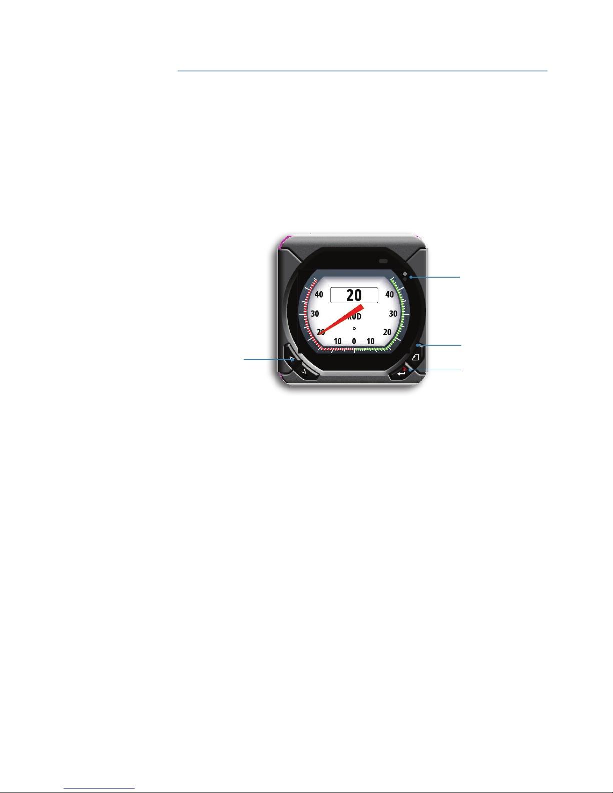
The IS40 PRO Display
1
4
3
2
1 Enter/Backlight key
Used to enter the main menu, select sub menus and confirm
selection.
Hold 3 seconds for illumination setting.
2 Page key
If more pages than the Rudder Angle page have been enabled scrolls through the pages.
When in menu operation - navigates one step back.
When in calibration menu - moves digit cursor left/right.
3 Screen refresh indicator
Alternating dots when instrument is alive.
4 Arrow keys
Scroll up and down through selected menus/set values.
1
Page 7
| 5
Basic Operation | IS40 PRO Operator Manual
Turning the IS40 PRO on and o
The IS40 PRO has no Power key, and it will be running as long as
the power is connected.
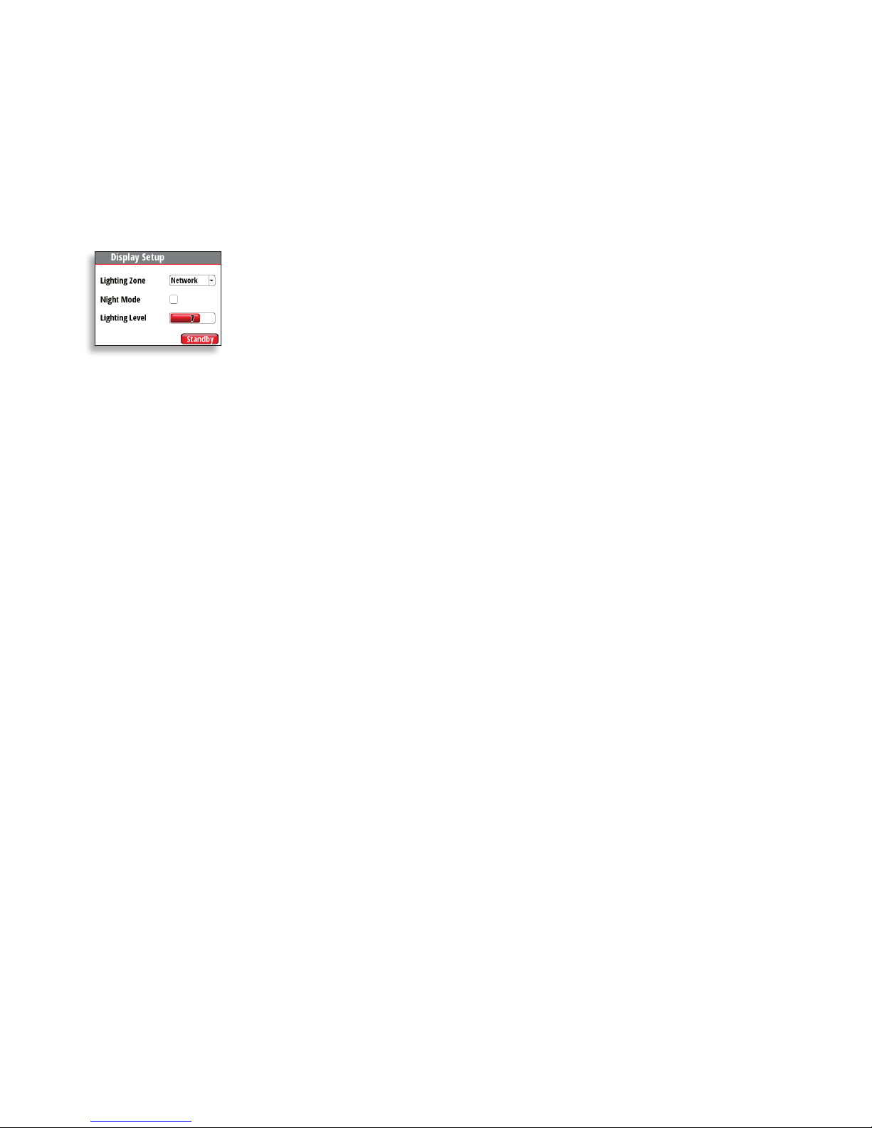
Display Lighting
Press and hold the Enter key for 3 seconds to display the Display
Setup dialog.
The Lighting Level option is active by default, and you need to press
the Enter key to select the other options in the dialog.
1.
Use the Arrow keys to select an option.
2. Press the Enter key to confirm the selection. The frame around the option
is red by default and will turn green when selected to adjust values.
3. Use the Arrow keys to adjust the value.
4. Confirm the selection by pressing the Enter key.
Lighting zone
Set the lighting zone for the display. All units in the selected
Lighting Zone will mirror each others light settings. Default setting
is Network.
Night mode
Change the display to Night Mode color pallet. All displays in the
selected Lighting Zone will also change to Night Mode.
Lighting level
Adjust the backlight level from 0-10.
¼ Note: When set to level 0, the display backlight will be off and keys
backlight will be at a minimum.
When the IS40 PRO is powered on, the Lighting level will be as set
before the unit was powered off. The Night Mode option will be on
if it was enabled when the unit was powered off.
Standby
Turns off the backlight for keys and display. Press any key to return
to normal operation.
Page 8
6 |
Basic Operation | IS40 PRO Operator Manual
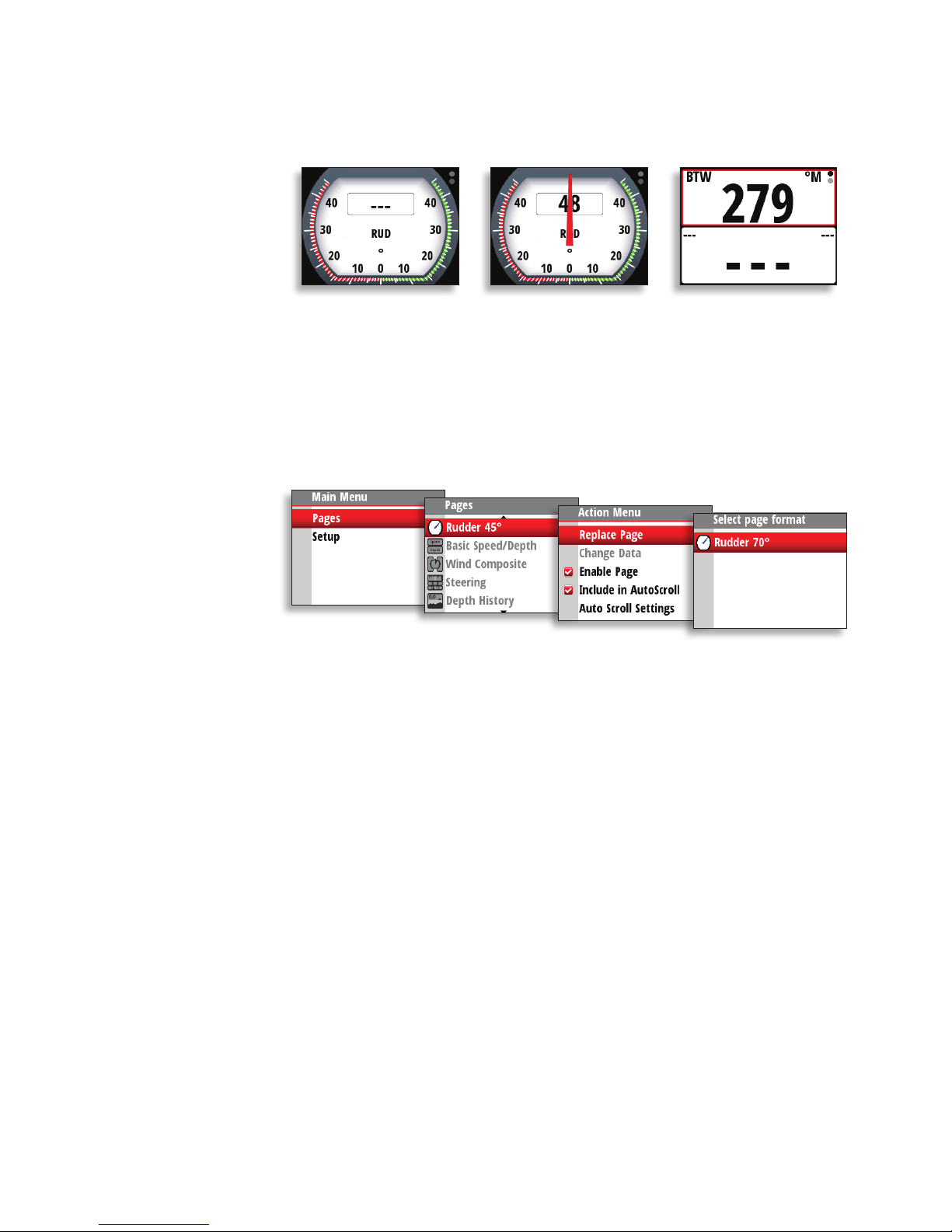
Missing or faulty data
If a data type is missing or if the data is out of scale, there will be no
data reading on the display.
Rudder Angle page with
missing data
Rudder Angle page with
data out of scale.
Digital page with missing
data
Setting up the Rudder Angle page
Factory default analog scale for Rudder Angle is ±45°. It can be
replaced by ±70° scale as shown below.
Page 9

| 7
Basic Operation | IS40 PRO Operator Manual
Optional data pages
From factory the display shows Rudder Angle page only. Six
additional data pages may be enabled to show a variety of boat
data and information available from sensors and devices on the
network.
¼ Note: Only the Rudder Angle pages are Wheelmark approved.
Below is an example with six additional pages enabled.
Each press of the Page key will change the current data page to the
next preselected page in the cycle.
¼ Note: If a data page has been shown for more than 5 seconds, first
press on the Page key will show Rudder Angle page.
¼ Note: Two or more pages need to be enabled for the Page key to
function.
Page 10

8 |
Basic Operation | IS40 PRO Operator Manual
Predened pages
¼ Note: These predefined pages are not Wheelmark approved.
Basic Speed / Depth
Two line data display. Boat speed and Depth
1. Refresh indicator
2. Boat speed
3. Depth
1
2
3
Wind
1. Apparent wind speed
(AWS)
2. Refresh indicator
3. True wind speed (TWS)
4. Apparent wind angle
(digital) (AWA)
5. Apparent wind angle
(analog)
6. True wind angle (TWA)
1
2
3
4
5
6
Page 11

| 9
Basic Operation | IS40 PRO Operator Manual
Steering
1. Compass graphic
(Heading)
2. Heading
3. Bearing to waypoint
(BTW)
4. Refresh indicator
5. Off track limit
6. Track
7. Boat position from
track
8. Cross track distance
graphic
9. Cross track distance
(XTD)
10. Course over ground
(COG)
11. Bearing to waypoint
indicator
3
8
4
9
7
6
1
2
5
10
11
Depth History
1. Depth value
2. Refresh indicator
3. Depth graphic
1
2
3
¼ Note: You can adjust the time period scale via the Arrow keys.
(Default = 10 min)
Page 12

10 |
Basic Operation | IS40 PRO Operator Manual
GPS
1. Refresh indicator
2. Course over ground
(COG)
3. Bearing to waypoint
(BTW)
4. Estimated time of
arrival (ETA)
5. Distance to waypoint
(DTW)
6. Speed over ground
(SOG)
7. Local time
8. Boat position (Lati-
tude & Longitude)
9. Coordinate system
3
6
7
1
5
8
4
2
9
¼ Note: GPS information relies on a suitable GPS connected to the
network and selected on the display as the current Position source.
Highway
1. Estimated time of arrival
(ETA)
2. Bearing to waypoint
(BTW)
3. Cross track distance
(XTD)
4. Distance to waypoint
(DTW)
5. Highway graphic
6. Next waypoint
7. Refresh indicator
8. Waypoint name
1
4
7
2
5
6
3
8
Page 13

| 11
Basic Operation | IS40 PRO Operator Manual
Enabling data pages
To make a data page available via the Page key you will need to first
ensure it has been selected as one of the seven available pages.
Once the page has been selected as one of the seven data pages
you can enable it as shown below:
Auto scroll
When selected, auto scroll automatically scrolls between the
enabled pages at a timed interval predetermined by setting the
desired scroll time in the auto scroll settings menu.
Include in auto scroll
To include a page in auto scroll, go to the auto scroll settings in the
action menu of the specific page and select Include in auto scroll.
Once selected a tick will appear in the check box.
Auto scroll settings
In the auto scroll settings menu you can start the auto scroll
function and set the time interval between page changes.
Page 14

12 |
Basic Operation | IS40 PRO Operator Manual
¼ Note: The scroll time interval can be set to change the displayed
data page between 1 and 10 second intervals.
Replacing a data page
Go to the pages menu. Select the page you wish to replace then
select the new page you would like to replace it with.
¼ Note: Rudder 45° page can only be replaced by Rudder 70° page.
Customizing a page
The content of the predefined pages can be changed when the
page is enabled. You can replace the page with another predefined
page, or you can use one of the template pages shown below.
Single data
item
0.0
Histogram
with a data
value
Two data
items
Analog
display
Four data
items
Full screen
analog
display
Highway
graphic
Nine data
items
1.
Select Pages from the main menu.
2. Select one of the predefined pages, then enable the page.
Page 15

| 13
Basic Operation | IS40 PRO Operator Manual
3. Select Replace Page.
4. Select one of the predefined pages to replace the page, or one of the
template pages if you want to create a customized page.
5. If you have used a template, select Change data and press the Enter key
to fill a field with data from the menu. Once selected, a tick will appear in
the check box. To populate other blank fields, press the Page key, select the
field using the Arrow keys and press the Enter key to add data to the field.
6. Press the Page key to view the display page, and press it once more to set it
as the prefered display page.
The image below shows how to change a page when using the Two
Line template.
Changing an analog display scale
For some full screen analog displays (not Rudder Angle) pressing
the Arrow keys will change the analog scale range. Select the scale
range to suit your environment and requirements.
¼ Note: If the actual recorded data is greater than the selected analog
scale, the analog needle will remain at the highest point on the
scale. The digital window in the center of the display will show the
actual value.
The example below shows the available scale range for the depth
analog set to meters. Pressing the Up Arrow key scrolls through the
available analog scales from 0-5 m through to 0 -200 m. Pressing the
Down Arrow key will decrease the analog scale.
0 - 5 m
0 - 200 m
Page 16

14 |
Setup | IS40 PRO Operator Manual
Setup
Sources
A data source can be a sensor or a device connected to the
network, providing information and commands to other networked
devices. The data sources are normally configured at first time turn
on. It should only be necessary to update this data if a new source is
added, source is missing (sensor failure), source has been enabled/
disabled, sensor replaced or a network reset.
Auto select
The Auto select option will look for all sources connected to the
instrument system. If more than one source is available for each
item, the display will automatically select from the internal device
priority list.
1. Verify that all interfaced units are powered on.
2. Press the Enter key to start the auto select procedure.
The operator will be noted when the auto select process is
completed.
¼ Note: If more than one source is available on the network, you can
chose your preferred source from the sources menu. See Manual
source selection.
2
Page 17

| 15
Setup | IS40 PRO Operator Manual
Manual source selection
If more than one source is available for an item, the preferred source
may be selected manually. As an example, the following illustrations
show how the rudder feedback source is changed.
Select the preferred data source. The selected source will be
indicated by a tick in the check box.
Device list
Shows a list of devices connected to the Network.
Selecting a device from the list will show you an information pane
with details of that device.
Some devices, such as RF70 and RC42 compass, store their
configuration, calibration and offset data in their own memory and
not in the instrument display memory. For devices of this type you
can check the data information, configure and calibrate the device
by selecting Options.
Page 18

16 |
Setup | IS40 PRO Operator Manual
Data
The data list shows the data type that the device is transmitting.
Congure
Instance
Enter a number to differentiate between instances of the same
device.
Oset
Certain devices will let you enter an offset value to compensate for
the position of the sensor or variation of sensor data.
¼ Note: Some devices can be configured further. If a device transmits
other data it may be shown on this page also.
Remote Displays
When B&G HV displays are available on the network, they can be
configured from the IS40 PRO. Follow the instructions on the screen
to get the desired data.
Calibration
Sensors that can be calibrated are listed in the calibration menu.
For magnetic Compass Heading sensors like RC42, calibration
is required. For calibration, select Calibration and follow the
instructions on the display.
Page 19

| 17
Setup | IS40 PRO Operator Manual
Rudder Feedback
The rudder feedback sensors RF70N and RF25N are calibrated from
factory. If there is a 1:1 relation between mechanical rotation of
rudder stock and rudder feedback shaft, and pointer deflection is
to the correct side, only zero alignment is required. If calibration is
required, start calibration as shown below and follow the sequence
on screen.
¼ Note: When entering angle values, Page key is used for left/right
digit selection.
Auto - Boat speed calibration via reference to GPS SOG
value
This is an AutoCal facility that uses speed over ground (SOG) from
your GPS and compares the average of SOG against the average
boat speed from the speed sensor for the duration of the calibration
run.
¼ Note: This calibration should be made in calm sea with no effect
from wind or tidal current.
1.
Bring the boat up to cruising speed (above 5 knots).
2. Select Auto on the Boat speed calibration page.
3. When the calibration is completed the Boat speed calibration scale will
show the adjusted percentage value of the boat speed.
Page 20

18 |
Setup | IS40 PRO Operator Manual
Use SOG as boat speed
If boat speed is not available from a paddle wheel sensor, it is
possible to use speed over ground from a GPS. SOG will be
displayed as boat speed and used also in the true wind calculations
and the speed log.
Manual adjustment of boat speed
Adjust the boat speed manually by selecting the Boat speed
percentage slider. Adjust the percentage up or down as desired.
Confirm the value. Select OK once complete.
Distance Reference
This option enables the user to calibrate the log accurately and
simply. Calculations are performed by the display that works out the
boat speed over a known distance.
To calibrate the boat speed via a distance reference you will need to
complete consecutive runs, under power at a constant speed made
along a given course and distance.
¼ Note: To eliminate the effect of tidal conditions it is advisable to
perform at least two runs, preferably three, along the measured
course.
Enter the desired distance in nautical miles that you would like to
calculate the distance reference over.
Page 21

| 19
Setup | IS40 PRO Operator Manual
When the boat gets to the predetermined starting position of the
distance reference calculation, start the calibration timer.
Referring to the diagram, A and B are the markers for each run and X
is the actual distance for each run as measured from a suitable chart.
Start Run 1
Stop Run 1
Stop Run 2
End Calibration
Start Run 2
Start Run 3
A B
X
As the boat passes marks A and B on each run, instruct the system
to start (Start Run) and stop (Stop Run) and finally OK to end
calibration (End Cal Runs).
After the last run is completed and OK has been selected, a pop-up
warning will ask you if you wish to replace the current calibration
with the new one. Select Yes to complete.
Page 22

20 |
Setup | IS40 PRO Operator Manual
Depth
A datum (offset value) can be set, such that the depth display refers
to either the water line or the base of the keel.
+VE: Positive Datum for Waterline
- VE: Negative Datum for Keel
(0.0)
Setting the depth offset displays depth readings from directly below
the keel or propellers of the boat, or from the waterline to the
seabed. This makes it easier to see the available depth, taking into
account the draught of the boat.
The offset value to be entered should represent the distance
between the face of the depth transducer, and the lowest part of
the boat below the waterline, or the distance between the face of
the depth transducer and the water surface.
Sea Temperature
If a suitable temperature sensor is fitted, the system will monitor the
current sea temperature.
The offset value to be entered should adjust the temperature
reading from the sensor to match a calibrated thermometer when
submersed in the water.
Page 23

| 21
Setup | IS40 PRO Operator Manual
Apparent Wind
This provides an offset calibration in degrees to compensate for
any mechanical misalignment between the masthead unit and the
center line of the vessel.
Set to positive (+) reading gives offset to Starboard. Set to negative
(-) reading gives offset to Port.
Compass Heading
The compass offset compensates for fixed errors (misalignment)
between the compass sensor and the direction of the boat.
To accurately enter a compass offset, the boat’s heading must be
referenced to, for example: a calibrated bowl compass .
The offset value will be the difference between the known source
and the currently displayed heading.
Enter this value as the offset in the compass heading field as a plus
or minus integer up to 180º.
Use COG as heading
If heading data is not available from a compass sensor it is possible
to use course over ground from a GPS. COG will be displayed as
heading and used in the calculation of true wind direction.
Time & Date
From the time and date menu you can set your preferred time/date
format and local time offset.
¼ Note: Local time is calculated based on UTC provided via a GPS unit
connected to the network.
Page 24

22 |
Setup | IS40 PRO Operator Manual
Units
Set the preferred unit of measurement you want data to be
displayed in.
Language
The display can be set to different languages to suit your preference.
Display setup
Set the Lighting Zone, enter Night Mode and change the Lighting
Level. See “Display Lighting” on page 5.
Show graphics
It is possible to turn on or off background graphics for some pages.
Example shown below.
Background graphics off Background graphics on
¼ Note: Graphics cannot be individually set on or off for each page.
Page 25

| 23
Setup | IS40 PRO Operator Manual
Damping
The damping rate effects the frequency that the sensor data
is updated on the display, the greater the damping value the
smoother the number change will be but the slower the response
will be to data change.
Decimal places
It is possible to change how many decimal places (1 or 2) speed and
sea temperature data will be displayed with.
Sounds
Turn the keypress sound on or off.
System
From the system menu there are several options to reset the system,
and get the current software information.
Network reset
Resets the source selection on all displays connected to the
network.
Reset to Factory
Resets the current display to the default settings. When the unit is
restarted you will see the original startup wizard asking you to set
the display.
Software information
Reveals the software you are currently running. See more
information on “Software information and upgrade” on page 25.
Page 26

24 |
Setup | IS40 PRO Operator Manual
Diagnostics
Shows an overview of the data being transmitted on the network.
The list shows the network bus status, bus load as a percentage as
well as quantity and type of data messages.
¼ Note: We recommend that you use this diagnostic tool as a basic
overview of the network status. For more detailed information it is
suggested that you check the individual source information via the
device list.
Page 27

| 25
Maintenance | IS40 PRO Operator Manual
Maintenance
General maintenance
The instruments are repair-by-replacement units, and the operator
is therefore required to perform only a very limited amount of
preventive maintenance.
If the unit requires any form of cleaning, use fresh water and a
mild soap solution (not a detergent). It is important to avoid using
chemical cleaners and hydrocarbons such as diesel, petrol etc.
Always put on the weather cover when the unit is not in use.
Checking the keys
Make sure that no keys are stuck in the down position.
Checking the connectors
The connectors should be checked by visual inspection only. Ensure
that cables are connected correctly and any unused terminals are
protected.
Software information and upgrade
To find out the latest version of software available for your display,
go to the Simrad website pro.simrad-yachting.com
To verify what software you are currently running, go to the software
information page on your display.
3
Page 28

26 |
Specications | IS40 PRO Operator Manual
Specications
Technical specications
Weight 0.28 kg (0.6 lbs)
Power
consumption
155 mA at 13.5 V
Network load 3 LEN (Load Equivalency Number)
Color Black
Display
Size 4.1” (Diagonal) 4:3 Aspect ratio
Type Transmissive TFT-LCD - White LED backlight
Resolution 320 x 240 pixels
Illumination White (day mode) / Red (night mode)
Environmental
Protection
IEC 60945 protected (IPX5)
Safe distance to
compass
0.2 m (0.6 ft)
Temperature -25 to +55 ºC (-13 to +131 ºF)
Dimensions
118 mm (4.65")
115 mm (4.53")
85 mm (3.35")
18.9 mm (0.74")
LTW
40mm (1.57")
84 mm (3.31")
17 mm (0.67")
4
Page 29

| 27
Specications | IS40 PRO Operator Manual
Wiring
1. IS40 PRO Display
2. Drop cable
3. CAN bus backbone
4. Mico-C T-Connectors
4
4
3
2
1
Menu ow chart
Main
Menu
Level 2 Level 3 Level 4
Pages Rudder 45°/70°
(Basic speed /
depth)
(Wind composite) Replace page Select page
format
(Steering) Enable page
(Depth history) Include in auto
scroll
(GPS) Auto scroll
settings
Start auto
scroll
(Highway) Scroll time
Setup Display setup Lighting zone Select group
Night mode
Lighting level
Standby
Remote Displays [List]
Calibration Rudder
Feedback
SOG
reference
Distance
reference
[List]
Page 30

28 |
Specications | IS40 PRO Operator Manual
Main
Menu
Level 2 Level 3 Level 4
Setup Time & Date Date format
Time format
Local time
Units [List]
Language [List]
Advanced settings Sources [List]
Device list Model ID /
Serial No.
Diagnostics [List]
Damping [List]
Decimal places Speed
Sea temp
Use COG as
heading
Use SOG as boat
speed
Show Graphics
Sounds Keypress sound
System Network reset
Reset to factory
Software
Information
Page 31

Page 32

*988-10840-001*
 Loading...