

Page 1

A brand by Navico - Leader in Marine Electronics
Manual
Simrad IS20 Graphic
Multifunction display
Page 2

Manual
Simrad IS20 Graphic
Multifunction display
To the best of our knowledge, the content in this
publication was correct at the time of printing.
As we are continuously improving our products we
retain the right to make changes to the product and
the documentation at any time.
Document no: 20222576
Revision: B
Date: March 2008
The original language for this document is English. In the
event of any discrepancy between translated versions
and the English version of this document, the English
document will be the official version.
Page 3

About this manual
This manual is a reference guide for installing and
operating the Simrad IS20 Graphic instrument.
The manual does not include operator or installation
procedures for sensors that can be connected to the
system.
In this manual, names of menu commands, dialog box
text and keys are written in boldface (e.g. Main menu,
Setup command, Left key).
Important text that requires special attention from the
reader is emphasized as follows:
Used to draw the reader’s attention to a comment or
some important information.
Used when it is necessary to warn personnel that a
risk of damage to the equipment or hazard exists if
care is not exercised.
)
Page 4

1 Introduction
General information
The IS20 Graphic is a multifunction instrument that
displays speed, depth, heading, position, wind and
environmental data measured by sensors and other
equipment connected to the system.
Navigational data, engine/battery status and vessel
parameters as e.g. accumulated log and rudder angle
may also be displayed.
The instrument calculates speed trim, wind head/lift,
trip distance and time, average speed, set and drift
parameters. A race timer is also included in the IS20.
Instrument layout
The IS20 has a 130 * 104 pixels LCD. The display may
be set to red or white illumination color, and the contrast
and light level are adjustable.
The instrument is equipped with 2 SimNet connectors,
an
d with one NMEA0183 input connector.
Keys
The instrument is operated by 6 keys. These are used to
adjust the light, scroll between data pages, to operate
the menu and to set parameter values.
Page 5
Softkeys
When the basic operation of the
keys is changed, softkey symbols
will be displayed right above the
keys to indicate the alternate
function.
The softkey symbols are illustrative, and they are
described under the functions as these appear in this
manual. The following general softkey symbols are used:
OK
Cancel
IS20 system examples
The IS20 may be installed as a stand-alone instrument
system, or as part of an advanced instrument or steering
system on the boat.
The figures on the next two pages show simplified
illustrations for basic and an expanded IS20 system.
Page 6

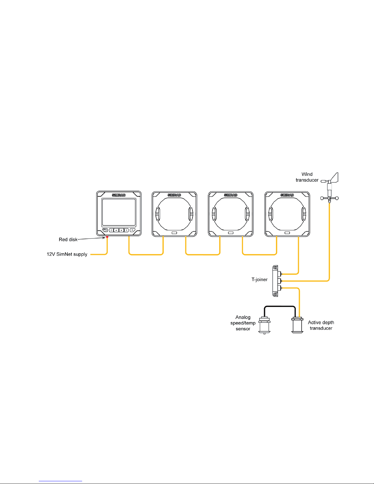
IS20 Graphic, Basic system
IS20 Graphic, Basic system with 2 sensors
Page 7
10 | Introduction
IS20 Expanded system
Page 8

2 Basic operation
It is required to read and understand the content in this
chapter. The remaining descriptions and illustrations in
this manual assumes that the user is familiar with how to
operate keys and how to navigate in the menus!
Turning the IS20 on
IS20 has no power key, and will be running as long as
power is connected.
The IS20 includes a power save function. Refer to page
19.
When power is connected, the start up page will show:
Product name
Serial number
Software version
Release date
After approximately 5 seconds the instrument is
operative.
First time start up
Before the IS20 is ready to operate, it should be
configured as described in Configuration, page 57 and
onwards.
Restarting the IS20 instrument
When IS20 is re-powered the display will go directly
to the last active page after the start up sequence is
finished.
-
-
-
-
Page 9
Backlighting
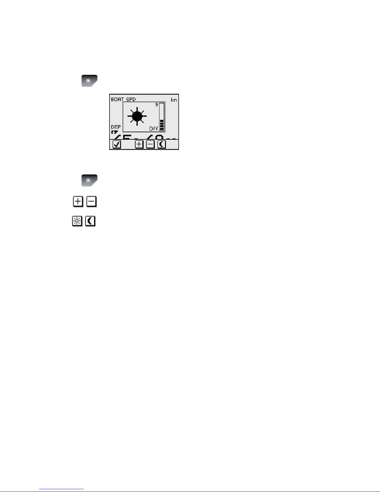
The display backlight may be adjusted at any time.
Press the light key
The Light level overlay window will
be displayed on top of the current
view.
Press one of the keys as described
below to change the display illumination:
The Light key to increase the light level by one
step
The Up/Down softkeys to increase/decrease
the light level by one step
The Day/Night softkey to toggle between day
and night prole
If n
o adjustment is performed within 3 seconds, the Light
level overlay window will disappear.
For contrast and day/night settings, refer to Changing
the display settings, pa
ge 39.
1
2
a
b
c
Page 10

Scrolling through data pages
The IS20 Graphic is pre-configured with 8 instrument
pages, of which 2 are disabled.
The instrument will scroll through the pages by using the
Up and Down keys .
Note that the pages shown with a
are disabled and
will not be visible when scrolling through the pages!
Default page
at first time
turn-on
Page 11
Resetting a data page
When a data page is active, the Right key may be used
to reset any calculated data.
The following data types may be reset:
Head/Lift
Speed trim
Trend graph
Pressing the Right key will have no effect if the active
data page not includes any calculated data!
Operating the menu system
All functions and settings in the
IS20 are available from the menu
system, activated by pressing the
Menu/Enter key.
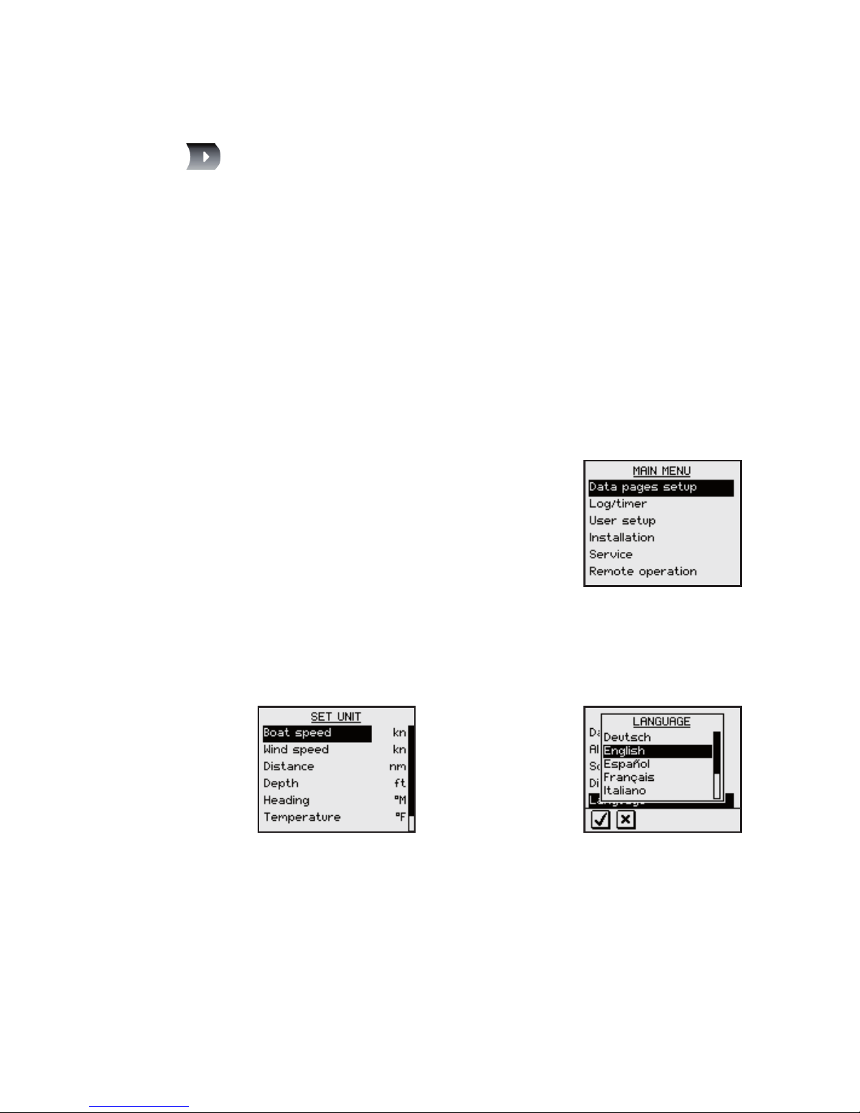
The main menu items give further
access to sub menus and various
se
ttings.
The set values are usually presented in the window’s
right column, but could also be listed in an overlay
window.
-
-
-
Unit settings presented
in the window’s right
column
Language settings
presented in an
overlay window
Page 12
Use the keys as shown below to navigate in the menu
system:
Key Single press Press and hold
Conrm a selection/parameter
setting
Go to next menu level/parameter
settings
Go to previous menu level/
parameter listing
Return to normal
operation and the last
active data page
Go to previous/next menu item,
increase/decrease parameter
value
When the basic operation of a key
is changed, a softkey symbol will
be displayed right above the key to
indi
cate the alternate function.
Page 13

The illustration below shows how to change the light level
from 4 to 2.
Press and holding the Left key will always return the
display to normal operation and the last active page!
Page 14
Menu illustrations
In this manual, the first
steps in a menu operation
are illustrated by overlapping
menu windows.
When more detailed illustrations are required to show
key presses and screens, this is shown as below:
Disabling/enabling data pages
By disabling a data page, the number of pages will be
reduced when scrolling through the data pages.
A disabled page is only visible when using the Enable/
Disable item in the DATA PAGES SETUP menu, and is
then indicated with a crossed rectangle!
Page 15

Disabling pages
Continue to select pages and repeat the procedure if
more pages are to be disabled.
Enabling a page
Continue to select pages and repeat the procedure if
other pages are to be enabled.
Page 16
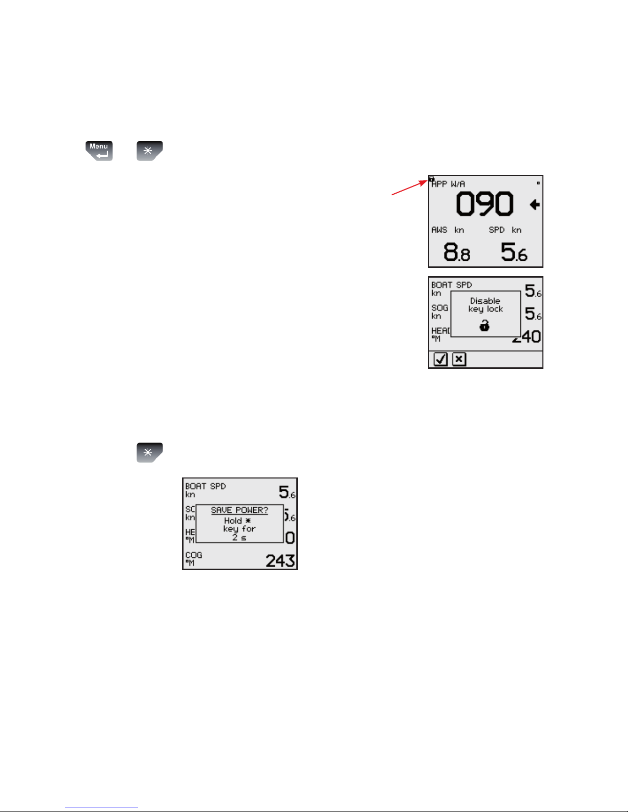
Locking and unlocking the keys
The IS20 keys may be locked to prevent any unintended
operation.
The key lock function is enabled by pressing the Menu/
Enter and the Light keys simultaneously.
A locked instrument has a
padlock symbol in the upper left
corner.
When the keys are locked, any key
press will activate the Disable
key lock overlay window. The key
lock function is then disabled by
pressing the Menu/Enter key.
Power save function
The power save function is activated by pressing and
holding the Light key for 3 seconds.
A dialog will show how long the
Light key has to be pressed before
the function is acivated.
When power save is activated, the display will be turned
off.
Any key press or activated alarm will disable the power
save function.
+
Page 17
3 Advanced operation
The advanced features described in this section are not
required for basic operation of the instrument!
Customizing the data pages
IS20 Graphic is capable of displaying 8 pages. These
are pre-configured from factory, but they are all user
configurable.
The number of pages may be reduced by disabling one or
more pages.
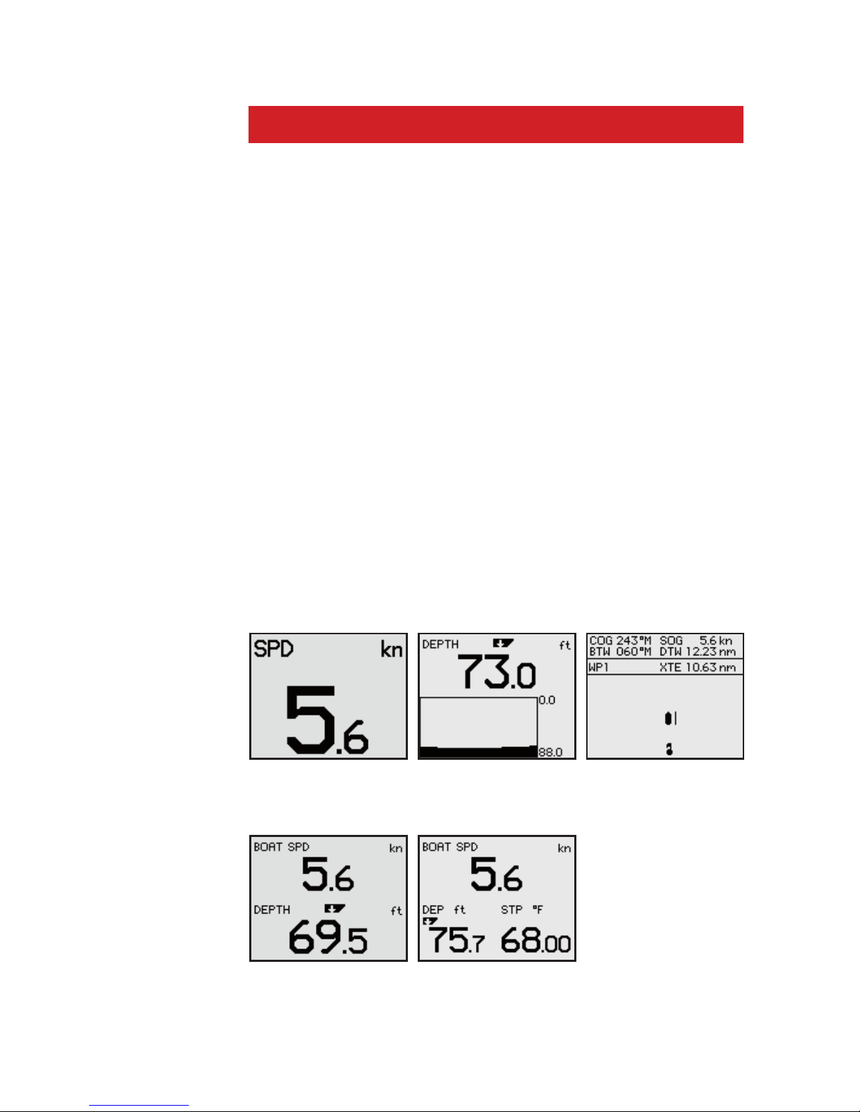
Data page windows
Each page may be set with numeric data items in up to 4
windows, with a combination of one numeric data window
and a trend window, or with a graphic “highway” view.
The illustrations below show examples of pages with the
various page options.
Single window Single window/
trend
Single window/
highway
2 windows 3 windows
Page 18

Changing the page layout
All data pages are user configurable.
The illustrations below show how a 4-window page is
configured.
Press and hold the Left key to leave the menu and return
to normal operation when all windows are defined.
For a list of all available data groups and data items,
refer to Data groups and data items.
4 windows/
horizontally
4 windows/
square
Page 19
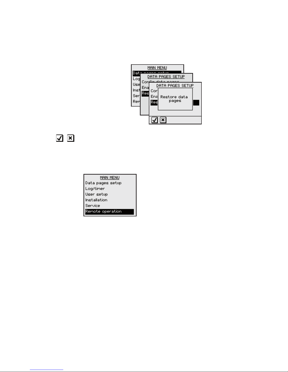
Restoring factory default pages
All user defined data pages may be restored to factory
default layout and content.
Use the keys to confirm or cancel and return to the
menu.
Remote operation
This function is for future use.
SimNet group function
The SimNet group function provides global control of
groups of units. This option is used on larger vessels
where many units are connected via the SimNet network.
By assigning several units to the same group, a function
change or update on one unit will have the same effect
on the rest of the group members.
Page 20

The table below shows available SimNet groups.
Function Groups Default
Display Simrad, None, 1-6 Simrad
Sources Simrad, None Simrad
Units Simrad, None, 1-6 Simrad
Language Simrad, None, 1-6 Simrad
Damping Simrad, None, 1-6 Simrad
Alarm Simrad, None, 1-6 Simrad
Power save Simrad, None, 1-6 None
Simrad: Default group for IS20
None: Not assigned to a group
1–6: Group numbers
The figures on next page illustrates how the instruments
on a flybridge and in a cockpit are assigned to separate
language, damping and display groups, and how this
affects the setup for the different instruments.
The SimNet groups are congured during system
configuration. Further information about how to set up
the groups are found in SimNet groups.
-
-
-
Page 21

BACKLIGHT = 1
LANGUAGE =
NONE
BACKLIGHT = 2
DAMPING = 1
FLYBRIDGE
COCKPIT
Page 22

Changing the SimNet group setup
The SimNet groups are normally configured during
installation, but may be changed at any time.
Demo mode
The IS20 includes a demo mode, useful for
demonstrations and on show.
Active demo mode is indicated
with flashing DEMO text in the
upper right corner of the page.
The demo indication will flash
more frequently on the demo
source than on units that are
reading the demo values.
When demo mode is selected on a unit in a system of
interconnected SimNet products, they will all go to Demo
mode.
Demo mode is turned OFF by using the menu as
illustrated above. An automatic source selection will then
be performed.
Demo mode must be turned OFF on the same unit where
Demo mode was turned ON!
Page 23

4 The log/timer functions
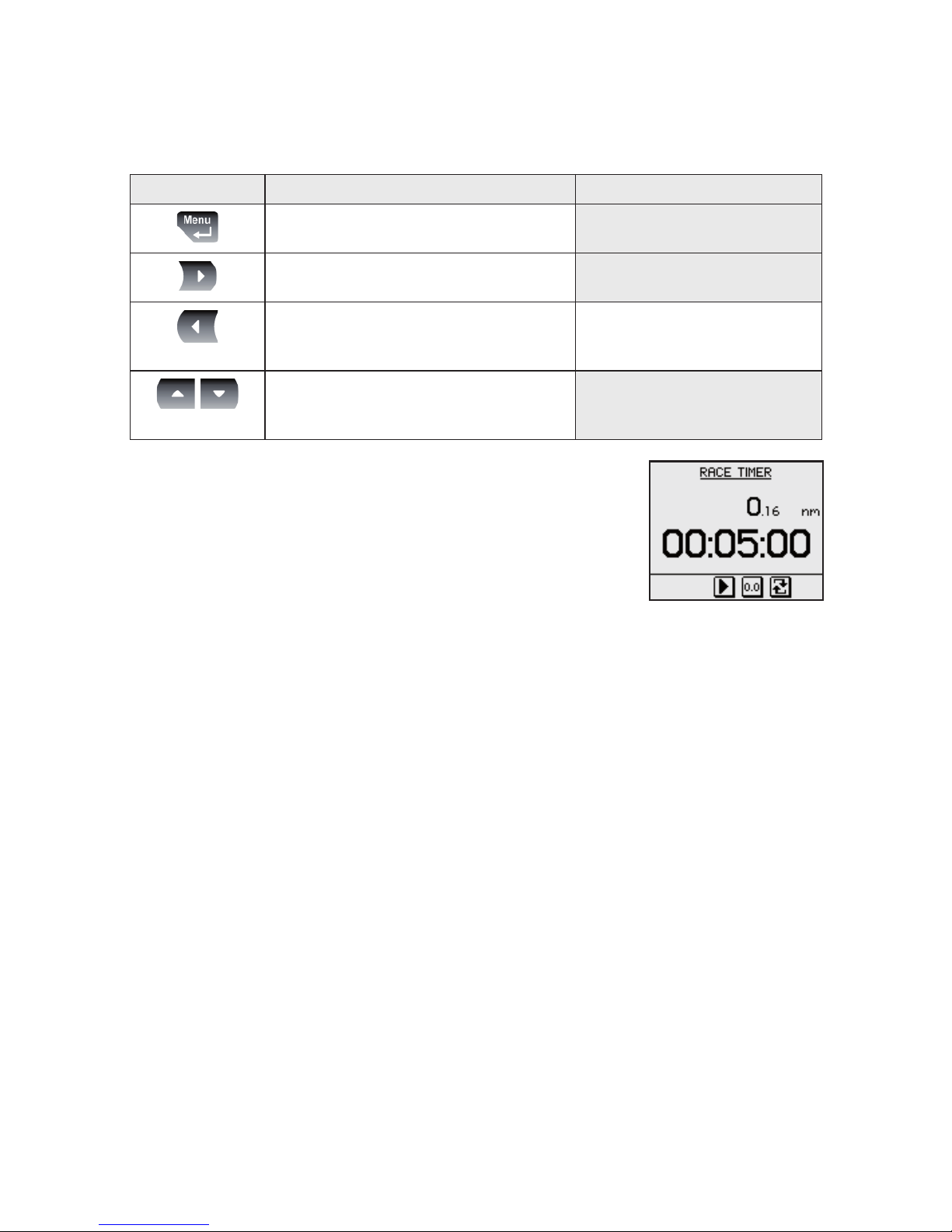
The timer function
The timer function is used to measure time and distance
after a race start.
When a timer page is displayed,
basic key operation is replaced by
functions indicated by softkeys.
The timer is by default shared between interconnected
SimNet units, and all timer values will be identical. The
units can however be set up in separate SimNet Display
groups as described.
The softkey functions are further described in the
following pages.
Setting the countdown time
Range Change per step Default value
20 min - 1 1 min 5 min
If the countdown time is set to OFF, the timer function
will work as a passage log and timer!
Page 24

Starting the race timer
The race timer will continue to run until the Stop softkey
is pressed even if the race timer page is replaced by
another page!
When the counter turns zero, the
race log starts to log the distance,
the Synchronize softkey is
removed and the timer function will
work as a race timer!
Stopping and restarting the timer
Stop the timer by pressing the Stop softkey.
The timer will stop counting, and the softkeys will
change status
Restart the race timer from the stopped time by pressing
the Start softkey.
The race timer and race log can be stopped when
counting down or counting up!
-
Page 25

Resetting the timer
A stopped or paused timer is reset to the pre-set
countdown time by pressing the Reset softkey.
Synchronizing the timer
The countdown timer may be synchronized to the nearest
whole minute at any time by pressing the Sync softkey.
The synchronize softkey will not appear if the counter has
turned zero!
Freezing the display
The timer display may be frozen at any time while the
timer is running. When the display is frozen, the timer
remains counting in the background.
Freeze the timer display by pressing the Freeze softkey.
The Freeze softkey will appear as
depressed
Re-press the Freeze softkey to return to the countdown
view.
Page 26

Trip logging
The trip log display shows:
accumulated total
distance since the
instrument was installed
or from a factory reset
distance and time since
the trip log was started/
reset
Resetting the trip log
The trip log is reset to zero by pressing the Reset softkey.
Speed logging
The speed log display shows:
Current speed
Max and average speed
since the speed log was
reset
Resetting the speed log
The speed log will automatically reset when the race
timer function is active and turns zero.
The speed calculation is manually reset to zero by
pressing the Reset softkey.
-
-
-
-
Page 27

Setting the time offset
The time function in IS20 is only available when a GPS is
connected to the system.
The GPS runs on UTC time, and can be adjusted to show
local time by entering a UPC offset value.
Range Change per step Default value
+14 h - –12 h 0.5 hours 0 hours
Page 28

5 Changing the default settings
General
The factory default settings may all
be changed from the User setup
command in the Main menu.
Updating the settings will affect all instruments in the
SimNet group. Refer to SimNet group function.
Setting the damping factors
The damping factors indicate how fast the display will
respond to changes.
The higher damping factor the more stable display
reading on the instrument.
Range Change per step Default value
0-9 1 4
Page 29

Alarm setup
The IS20 may be set up to sound an alarm if vessel or
environmental parameters exceeds preferred values.
The alarm monitoring is disabled by setting the value to
Off.
Boat speed alarm
Used to give alarm if the boat speed goes beyond a
selected value.
Range Change per step Default value
Off - 50 kn 1 kn Off
50 - 60 kn 5 kn Off
Page 30

Depth alarm
The depth alarm can be set up for deep and shallow
water limits.
An anchor alarm can be activated to warn if the boat is
drifting. The alarm will sound when during a 40 seconds
ti
me period there is a change in depth of 2-3 meters
(6–10 ft).
The Anchor alarm should be turned Off when the boat is
not at anchor!
Alarm Range Change per
step
Default
value
Deep Off - 650 ft 1.
6-5: 0.1 ft
5-10: 0.5 ft
10-50: 1 ft
50-100: 5 ft
100–500: 10 ft
500–650: 50 ft
Off
Shallow Of
f – 320 ft 1.6-5 0.1 ft
5–10: 0.5 ft
10–50: 1 ft
50–100: 5 ft
100–320: 10 ft
Off
Anchor Off – On - Off
Page 31

Wind alarm
The wind alarm can be set for high and low wind speeds.
The wind shift alarm will monitor the wind angle. The
reference angle is set when the alarm is turned on,
and reset to present wind angle when an alarm is
acknowledged.
Alarm Range Change per
step
Default
value
High speed Off - 60.0 kn 1–
50: 1 kn
50–60: 5 kn
Off
Low speed Off - 60.0 kn 1–
50: 1 kn
50–60: 5 kn
Off
Shift 5° - 90°M 1°M Off
Page 32

Updating the data sources
A data source can be a sensor or a device connected to
SimNet, providing information and commands to other
SimNet devices.
The data sources are normally configured at first time
turn on. It should only be necessary to update this data
if a new source is added, if a source is missing (sensor
failure), or if a source has been switched off/on.
Automatic source update
The Auto select option will look for all sources
connected to the instrument system. If more than
one source is available for each item, the IS20 will
automatically select from an internal SimNet priority list.
Verify that all interfaced units are powered on
Press the Menu/Enter key to start the auto select
procedure
The operator will be noted when the
Auto select process is completed.
If more than one source is found for each source item,
see Manual source selection.
1
2
Page 33

Manual source selection
If more than one source is available for each item, the
preferred source may be selected manually.
As an example, the following illustrations show how the
compass source is changed.
Select the preferred data source and confirm with the
OK softkey.
Displaying source information
Page 34

Changing the display settings
The display is controlled by two user profiles that can be
individually adjusted.
The profiles are Day profile and Night profile. The
profiles can be optimized for readability under different
light conditions, and you can quickly switch between the
two using the Light key. Refer to Backlighting.
For each profile you can:
Adjust light level
Select white or red light color
Invert the display
Adjust the contrast
The display settings also apply for the keys!
Setting Range Change per
step
Default
value
Light level 9 – Off 1
3 (
Day)
5 (Night)
Light color White/Red -
White (Day)
Red (Night)
Invert
display
Yes/No - No
Contrast 0 - 9 1 4
-
-
-
-
Page 35

Language selection
The language is usually selected when the instrument is
turned on for the first time. Refer to First time start-
up, page 57.
It is, however, possible to change the language at any
time.
The following languages may be selected:
Deutch (German)
English (English)
Español (Spanish)
Français (French)
Italiano (Italian)
Nederlands (Dutch)
Norsk (Norwegian)
Svenska (Swedish)
The language names are listed alphabetically in their own
language.
Default language: English
-
-
-
-
-
-
-
-
Page 36

Changing the units of measure
Parameter Options Default value
Boat speed - kn
- kmh
- mph
kn
Wind speed - kn
- m/s
- mph
kn
Distance - nm
- mi
- km
nm
Depth - m
- ft
ft
Heading - °M
- °T
°M
Temperature - °C
- °F
°F
Volume - gal
- L
gal
The display unit for heading data is not solely determined
by the user. If true heading is wanted, but the selected
compass is a magnetic compass, then the magnetic
variation must be available from a position source. The
same applies if the user wants to read magnetic heading,
but receives true heading from the compass.
If magnetic variation is required, but not available, the
compass decides which unit to display.
Page 37

6 IS20 Alarm system
Alarm indication
The alarm system in IS20 Graphic is activated if any
alarm settings are exceeded. Refer to Alarm setup,
page 34.
When an alarm is notified, the
alarm will be indicated with an
alarm text and with an audible
alarm.
The different alarm indications are
shown in the table below.
Alarm type Sound Light
Reminder
interval
Vital alarm
Alternating
between 2
tones
Switching
on/off
10s
Important
alarm
20s
Standard
alarm
40s
Warning Single beep 60s
Light warning Single beep
If IS20 Graphic is connected to other SimNet units, any
alarm in the system will be displayed on the instrument.
If no specific alarm text is displayed, an alarm code will
appear. Refer to Alarm codes.
Page 38

Acknowledging an alarm
An alarm is acknowledged by pressing any key. This will
remove the alarm notification (text, light and sound)
from all units that belongs to the same alarm group.
Refer to SimNet group function
A reminder will reappear at given
intervals for as long as the alarm
condition exists.
An alarm received from other SimNet units must be
rectied on the unit generating the alarm!
Viewing active alarms
A list of any existing alarm condition may be displayed at
any time.
Alarm codes
If the alarm is received from other units connected to
SimNet, the alarm text may not be displayed. The alarm
condition will then be indicated in a code.
A description for available codes is listed in the table on
the next page.
Page 39

Alarm ID Alarm
10 Shallow water
11 Deep water
12 Anchor alarm
13 Wind shift
14 True wind speed too high
15 True wind speed too low
16 Boat speed too low
17 Voltage too high
18 Voltage too low
19 Depth data missing
20 Wind data missing
21 Nav data missing
22 Compass data missing
23 Off course
24 Rudder data missing (RF25)
25 R
u
dder feedback failure (RF300)
26 Rudder response failure
27 Drive overload
28 High temperature
29 Bypass/clutch overload
30 Bypass/clutch disengaged
31 High drive supply
32 Low drive supply
33 No active Autopilot control unit
34 No Autopilot computer
35 ACXX Menory failure
36 No connection with EVC system
37 EVC overdrive
56 RF must be calibrated
Page 40

7 Installation
Location of the unit
The IS20 should be mounted with special regard to the
unit’s environmental protection, temperature range and
cable length. Refer to page 75.
Avoid mounting the control unit(s) where it is easily
exposed to sunlight, as this may shorten the lifetime of
the display.
Mechanical installation
Panel mounting
The mounting surface must be flat and even to within 0.5
mm.
Drill the 4 mounting holes and make a panel cutout according to the drilling template included in
the package
Use the supplied 19 mm selftapping screws to
secure the control unit to the panel
Apply the front panel corners
Do not over-tighten the screws!
1
2
3
Page 41

Bracket mounting
An optional bracket is available for the IS20.
The illustration below shows the mounting details for the
bracket.
Page 42

Cable connection
The IS20 may be connected to:
a SimNet network using SimNet cables
an NMEA2000 system
an N
MEA0183 input port
SimNet
The SimNet cable system with very small plugs in both
ends makes it easy to run the cables. Only 10 mm (3/8”)
holes are required through panels and bulkheads.
The SimNet accessory program contains the necessary
items to make a successful installation. Refer to SimNet
cables and accessories.
SimNet cables
A SimNet unit has one or two yellow SimNet connectors.
There are no dedicated “in” or “out” connectors.
Route the SimNet cables with the figures on page 51, 52
and 53 a
s a guideline. Select cables and accessories from
the SimNet accessory program.
Connect products with two SimNet connectors in a daisy
chain and use drop cables and T-joiners when required.
For cable extension in-line cable joiners are available.
Total length of SimNet cable installed in a system should
not exceed 150 meter (500’)!
-
-
-
SimNet/
NMEA2000
SimNet/
NMEA2000
NMEA0183 In
Page 43

If you plan to extend your SimNet system in the future it
may be advantageous to prepare for it by adding a few
T-joiners in central locations. The T-joiners provide easy
access to the network and can be replaced with a new
product, or the new product can be connected via a drop
cable.
The connectors are weather proof according to IP66,
when properly installed. All unused SimNet connectors
must be tted with the plastic cap to protect them
against dirt and moisture.
SimNet power and termination
The following rules should be observed when installing
SimNet:
It must have a separate 12VDC power from the
battery bus or the circuit breaker board to reduce
interference
It must not be connected to the supply voltage
terminals of the Autopilot Computer
It will power a SimNet compatible instrument
system. Hence SimNet to other equipment can be
supplied via the autopilot
SimNet must be properly terminated, i.e. unless it
is a small system (see the gure on page 51) there
must be terminations at each end of the Simrad
backbone
The SimNet network has to be terminated according to
the number and type of products connected.
In a small system consisting of maximum 5 SimNet
products and a total length of 5 m SimNet backbone
cable, you only need the SimNet power cable with built-in
termination (red disc on cable plug).
For additional information about SimNet, ask for the
separate SimNet Manual.
1
2
3
4
Page 44

SimNet network, small system
Page 45

52 | Installation
SimNet network, medium system
Page 46

Installation | 53
SimNet network, expanded system
Page 47

Maximum total length of SimNet cables is 150 m
(500 ft.)
Drop cables must not exceed 6 m (19 ft) of length
and the total length of drop cables must not
exceed 60 m (200 ft).
Equipment should not be daisy-chained in a drop
cable.
The wind transducer (*) has a built-in terminator.
Connecting IS20 to an NMEA2000 network
No daisy-chain connection is permitted between SimNet
units when connected to an NMEA2000 network!
Use the SimNet cable (part no. 24005729) to connect the
IS20 to an NMEA2000 network.
1
2
3
4
Page 48

Connecting IS20 to an NMEA0183 output unit
The IS20 instrument may be used as repeater for data
from a device with an NMEA0183 output port (NMEA
“talker”).
Use a repeater that is dedicated for the type of data you
want to present and the way you want it presented, i.e.
digital or analog, multiple data from a GPS/Chart plotter
or heading from a compass.
Us
e the NMEA0183 Interface cable (part no. 22098495)
to connect an NMEA0183 output device to IS20.
Page 49

8 Conguration
First time start-up
When the IS20 is powered on for the first time, the
instrument will run through an automatic start-up
sequence, presenting:
Product name, serial number, software version,
release date
Language selection
Automatic data source selection
Press the Menu/Enter key when the start-up procedure
is completed. This will change the display to the default
Speed/Depth/Temperature page.
1
2
3
Page 50

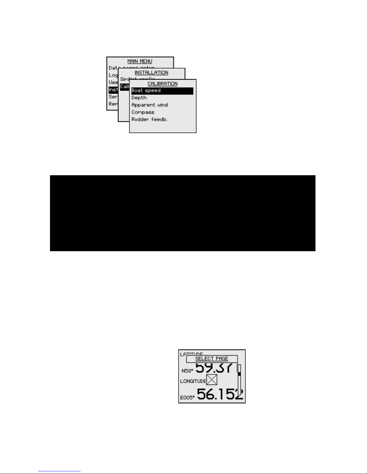
Calibration
After installation, certain functions in the system must be
calibrated to adapt to the physical position and type of
sensors installed.
All calibration is initiated from the CALIBRATION sub
menu.
Boat speed
The hull shape or the location of the speed sensor
may cause incorrect speed readings, and calibration is
required to ensure that correct speed and log readings
are displayed.
Page 51

Calibrate by speed over ground
With a GPS connected to the system, the speed may
be automatically set identical to the speed over ground
value.
This adjustment should be made in calm sea with no
effect from wind or tidal current.
Bring the boat up to cruising speed (above 5 knots)
Select Calibrate w/SOG and press the Menu/
Enter key to start the calibration
When the calibration is completed the SPD
Correction factor is set to 1.00
Manually adjust the speed value
If you experience an incorrect speed reading this can be
manually re-adjusted as follows:
Compare the speed reading with that on another
boat
Run the boat at constant speed over a known
distance in both directions and average the speed
reading
Then adjust the SPD Correction factor to get the
correct speed reading.
Range Change per step Default value
-0.50 - +1.50 0.01 1.00
1
2
3
-
-
Page 52

Depth
The default value for the depth offset is 0.0, which
indicates the displayed depth from the transducer to the
seabed (b). Refer to the illustration on the next page.
The value should be increased or decreased, depending
on whether the depth reading should be from the water
line or from the keel, respectively:
A negative offset equal to the vertical distance
from the transducer to the keel will display the
depth as measured from the vessel’s keel (a)
A positive offset equal to the vertical distance from
the transducer to the water line will display the
depth as measured from the water line (c)
-
-
Page 53

The symbol in front of the depth reading will change to
indicate that the depth is measured from:
the keel or the water line
Range Change per step Default value Units
-10 - +10 0.1 0.0 m, ft
Page 54

Apparent wind offset
Any residual error in the apparent wind angle display can
be corrected manually by entering the required offset.
A positive value indicates starboard offset angle, a
negative value indicates port offset angle.
Range Change per step Default value Units
-180 - +180 1 0 °
Compass
The compass calibration and the heading offset function
affects the compass that is selected as heading source.
If more than one compass is connected to the system,
each compass have to be manually selected as compass
source (sensor) and calibrated separately. Refer to
Manual source selection, pa
ge 38.
The calibration procedure will have no effect on
earlier compass models from Simrad and non-Simrad
compasses!
Page 55

Compass calibration
Before the compass calibration is started, make sure that
there is enough open water around the vessel to make a
full turn.
The calibration should be done in calm sea conditions and
with minimal wind to obtain good results. Use about 6090 seconds to make a full circle.
Highlight the Calibrate line in the dialog
Begin turning the boat to port or starboard
Press the Menu/Enter key to start the automatic
compass calibration
An information window will be
displayed while the calibration
procedure is running.
The digits below the bargraph will
read 0.0 when the turn rate is
correct. Too high or too low speed
is indicated as follows:
The automatic calibration is completed when the
information window disappears from the display
1
2
3
4
Turn rate too high,
turning cw
Turn rate too low,
turning cw
Page 56

The FC40 and RC42 compasses will store the calibration
and offset data in their own memory.
During the calibration, the compass will measure the
magnitude and direction of the local magnetic field. If the
local magnetic field is stronger than the earth’s magnetic
field (the local field is reading more than 100%), the
compass calibration will fail. If the local field is reading
mo
re than 30%, you should look for any interfering
magnetic objects and remove them, or you should move
the compass to a different location. The (local) field
angle will guide you to the local interfering magnetic
object. See illustration on next page.
Calibration is made on the active compass.
If another model compass from Simrad or another
manufacturer is installed, refer to the instruction for that
compass regarding calibration.
Magnitude of local
field in % of earth’s
magnetic field.
Direction of local field
with respect to lubber
line. it can also be on
the reciprocal.
Lubber line Lubber line
Page 57

Mounting offset
After compass calibration, the heading should be
checked against a known reference, a compensated
compass or a bearing.
If the compass reading has a fixed
offset, use the Offset parameter to
compensate.
Range Change per step Default value Units
-180 - +180 1 0 °
Rudder
The rudder calibration is used to compensate for any
non-linearity in the transmission between the rudder and
the rudder feedback unit.
Page 58

Adjusting the maximum rudder angle
Select Max starboard and press the Menu/Enter
key to start the calibration
Manually turn the rudder to h.o. starboard position
Conrm that the actual rudder angle is identical to
the readout. Adjust the reading if necessary
Repeat the procedure for port rudder angle
Setting rudder zero position
This adjustment should be made in calm sea and side
forces from wind or current should be avoided.
Bring the boat up to cruising speed, and head
directly into the wind
If the boat has twin engines, synchronize the
engine RPM’s
Set the trim tabs and stabilizers to have no effect
on the boats heading
Steer the boat manually on a steady course
Select Set rudder 0 and press
the Menu/Enter key to conrm
Conrm the rudder zero
position
1
2
3
4
1
2
3
4
5
6
Page 59

SimNet groups
The SimNet group function is used to globally control
parameter settings in groups of units. The function is
used on larger vessels where several units are connected
via the SimNet network.
By assigning several units to the same group, a
parameter update on one unit will have the same effect
on the rest of the group members.
For additional information about SimNet groups, refer to
SimNet group function, pa
ge 23 and onwards.
Setting the unit’s instance number
The instance number is used to identify multiple units
of the same model when connected to a SimNet or
NMEA2000 network. The instance number is added to the
product name e.g. IS20-3 for easy identification of the
unit.
Range Change per step Default value
0-63 1 0
Page 60

9 Maintenance
General maintenance
The IS20 instruments are “repair by replacement” units,
and the operator is therefore required to perform only a
very limited amount of preventive maintenance.
If the unit requires any form of cleaning, use fresh water
and a mild soap solution (not a detergent). It is important
to avoid using chemical cleaners and hydrocarbons such
as diesel, petrol etc.
Make sure that all open SimNet connectors are fitted
wi
th a protection cap (part no. 24006355).
Always put on the weather cover when the unit is not in
use.
Service information
The main menu includes a
Service item giving access to
several options for displaying
data used when testing or
trouble shooting the system.
SimNet status
The SimNet status screen
provides status information
about the different SimNet
messages used by the
system.
Page 61

NMEA0183 status
The NMEA0183 status screen
lists status information
about available data
type, checksum error and
NMEA0183 version.
System data
The System data screen
provides status information
about the different NMEA
messages used by the
system.
Page 62

Resetting the instrument system
The reset options will reset the instrument to default
settings.
The Installation and Setup procedures must be
repeated after a reset has been performed!
Two different reset options are available:
Lo
cal reset: Resets the selected instrument
Global reset: Resets parameters on the selected
instrument and all other units that share
parameters with this instrument.
Displaying instrument information
By selecting the About IS20 menu item, an information
window will display instrument model, software version
number (1.0.), software release (02) and date of release.
The shown readout is only an example!
Page 63

10 Spare parts
Spares and auxiliaries
Part no. Description
22096010
IS20 Graphic instrument head
22096630
IS20 mounting kit including:
- 4 screws
- 6 corners
- 1 SimNet blocking plug
22096515
IS20 Weather cover
22096820
IS20 Mounting bracket
24006355
SimNet blocking plug
22098495 NM
EA0183 Interface cable 2.5 m (8’)
Page 64

SimNet cables and accessories
Art. no. Description
24005829 0.3
m (1’) SimNet cable (SDC:0.3M)
24005837 2 m (6.6’) SimNet cable (SDC:02M)
24005845 5 m (16.6’) SimNet cable (SDC:05M)
24005852 1
0 m (3
3’) SimNet cable (SDC:10M)
24005860 Si
mNet T-joiner (SDJ) (3p)
24006298 SimNet Multijoiner (7p)
24
006306 SimNet Bulkhead T-connector
24005878 SimNet cable gland
24005886 SimNet protection plug
24005894 SimNet termination plug
24005902 2 m (6.6’) SimNet power w/termination
24005910 2 m (6.6’) SimNet power w/o termination
2
4
005936 AT10 Universal NMEA0183 converter
24005944 AT15 Active T-connector, IS15
24005928 SimNet cable protection cap
24005729
SimNet cable to Micro–C male
Cable that connects a SimNet product to a
NMEA2000 network
24006199
SimNet cable to Micro-C female cable that
connects a NMEA2000 product to SimNet
24
006363 SimNet cable, 5.5 m (18’), with 1 plug
Page 65

11 Specications
Technical specications
Weight: ......................................................... 0.3 kg (1.1 lbs)
Power consumption: ..................................................... 1.3
W
SimNet Network Load (NL): ............................................2 NL
Color: ..........................................................................Black
Display:
Type: .........................................Backlit LCD matrix display
Resolution: ............................................. 130 x 10
4 pixels
Illumination (Red or white): ............... Adjustable in 10 steps
Environmental protection:
Front: ...................................................................... IP56
Back: ......................................................................I
P
43
Safe distance to compass: .................................0.3
m (1.0 ft.)
Temperature:
Operating: ............................ 0 to +
55 °C (+32 to +130 °F)
Storage: ............................ –30 to +
70 °C (–22 to +158 °F)
Page 66

Dimensional drawings
Page 67

Menu low chart
Page 68

Data groups and data items
DATA GROUP DATA ITEM DESCRIPTION
Speed/Depth BOAT SPD Boat speed
SOG Speed over ground
VMG Velocity made good to wind
VMG WPT
VMG to waypoint (Waypoint
Closure Velocity, WCV)
SPD TRIM Speed trim
DEPTH Current depth
Wind APP W/S Apparent wind speed
APP W/A Apparent wind angle
TRUE W/S True wind speed
TRUE W/A True wind angle
TRUE DIR True wind direction
HEAD LFT Head lift
TACK HDG Tack heading
Log/Timer STD LOG Stored log
TRIP LOG Trip log
TRIPTIME Trip time
AVG SPD Average speed
MAX SPD Max speed
RACE TMR Race timer
RACE LOG Race log
Vessel HEADING Heading
RUDANGLE Rudder angle
COG Course over ground
MAGVAR Magnetic variation
SET Direction of current flow
DRIFT Speed of current
LATITUDE Latitude
LONTUDE Longitude
UTC Coordinated Universal Time
TIME
Local time at vessel
position
Page 69

DATA GROUP DATA ITEM DESCRIPTION
Navigation BRG WPT Bearing to next waypoint
DST WPT Distance to next waypoint
XTE Cross track error
ETA WPT
Estimated time to next
waypoint
TIME WPT Time to next waypoint
WPT
Next waypoint number and
name
Engine/Battery ENG1 RPM Engine 1 RPM
ENG2 RPM Engine 2 RPM
LEVEL 1 Fuel level tank 1
LEVEL 2 Fuel level tank 2
ENG1 RTE Engine 1 fuel rate
ENG2 RTE Engine 2 fuel rate
VOLTS 1 Battery voltage 1
VOLTS 2 Battery voltage 2
Environment SEA TEMP Sea temperature
AIR TEMP Air temperature
BARO PR Barometric pressure
HUMIDITY Outdoor humidity
 Loading...