

Page 1
Installation manual
38/200 Combi C
Echo sounder transducer
www.simrad.com
M A X I M I Z I N G Y O U R P E R F O R M A N C E A T S E A
Page 2

Page 3

851-165182
38/200 Combi C
Transducer
Installation manual
Warning!
The transducer cable must not be exposed to oil
or other petroleum fluids. See page 1 inside!
Page 4

About this document
Rev Date Written by Checked by Approved by
Rev.B
18.05.05 RBr OBG OBG
Added more information about cable glands.
© 2005 Simrad AS. All rights reserved.
ISBN 82-8066-051-8
No part of this work covered by the copyright hereon may be reproduced or otherwise
copied without prior permission from Simrad AS.
The information contained in this document is subject to change without prior notice.
Simrad AS shall not be liable for errors contained herein, or for incidental or
consequential damages in connection with the furnishing, performance, or use of this
document.
The equipment to which this manual applies must only be used for the purpose for
which it was designed. Improper use or maintenance may cause damage to the
equipment or injury to personnel. The user must be familiar with the contents of the
appropriate manuals before attempting to operate or work on the equipment. Simrad AS
disclaims any responsibility for damage or injury caused by improper installation, use
or maintenance of the equipment.
If you require maintenance on your Simrad equipment, contact your local dealer. You
can also contact Simrad using the following e-mail address: fish-support@simrad.com
Page 5

INTRODUCTION
Purpose
The purpose of this installation manual is the provide the basic
information required to install the 38/200 Combi C echo
sounder transducer.
Note that although drawings are provided to explain the
installation principles, the installation shipyard must provide the
final drawings required to fit each individual vessel. Also, when
applicable, the installation shipyard must have the drawings and
installation approved by the proper authorities.
Transducer order no: KSV-202192
Cable gland kit 599-202182 is included with the delivery. Other
cable glands must be ordered separately.
Installation manual
Transducer installation
The next chapter in this manual provides generic guidelines for
transducer installation. The drawings specific for the 38/200
Combi C transducer are located in the Drawing file.
Warning!
The transducer cable must not be exposed to oil or other
petroleum fluids.
Technical specifications
Refer to the 38/200 Combi C product specification, Simrad
document number 855-164053.
851-165182 / Rev.B
1
Page 6

Simrad 38/200 Combi C Transducer
INSTALLATION
This chapter provides general installation guidelines for
transducer installation. The following topics are described:
• Transducer location
• Mounting (different methods are shown when applicable)
• Cable glands
• Steel conduit for transducer cable
• Handling and maintenance
• Approved anti-fouling paints
The information in this chapter must be regarded as general
guidelines and recommendations only. The installation shipyard
must design and manufacture installation hardware to fit each
individual vessel.
Whenever required, the installation shipyard must also have the
installation approved by the applicable maritime authorities.
2
851-165182 / Rev.B
Page 7

Installation manual
Transducer location
General
A single answer to the question where to locate the transducer
cannot be given. It depends very much on the vessel’s
construction. However, there are some important guide lines.
Go deep
The upper water layers of the sea contain a myriad of small air
bubbles created by the breaking waves. In heavy seas the
uppermost 5 to 10 metres may be air-filled, with the highest
concentrations near the surface. Air bubbles absorb and reflect
the sound energy, and may in worst cases block the sound
transmission totally. Therefore, mount the transducer at a deep
position on the hull.
Consider the situation when the vessel is unloaded, and when it
is pitching in heavy seas. The transducer must never be lifted
free of the water surface. Not only will the sound transmission
be blocked, but the transducer may be damaged by slamming
against the sea surface.
Another reason to go deep is cavitation in front of high power
transducers. Cavitation is the formation of small bubbles in the
water due to the resulting local pressure becoming negative
during parts of the acoustic pressure cycles. The cavitation
threshold increases with the hydrostatic pressure.
Vessel heave
Heave is the up and down movement of the vessel. It disturbs
the echo traces in the echogram, so that a flat bottom is
displayed as a wave. A transducer location in the middle of the
vessel minimises the influence of vessel roll and pitch.
Noises from protruding objects on the hull
Objects protruding from the hull, such as zinc anodes, sonar
transducers or even the vessel’s keel, generate turbulence and
flow noise. Also holes and pipe outlets are noise sources. They
may act as resonant cavities amplifying the f low noise at certain
frequencies. Do not place an echo sounder transducer in the
vicinity of such objects, and especially not close behind them.
For the same reason, it is very important that the hull area
around the transducer face is as smooth and level as possible.
Even traces of sealing compound, sharp edges, protruding bolts
or bolt holes without filling compound will create noise.
851-165182 / Rev.B
3
Page 8
Simrad 38/200 Combi C Transducer
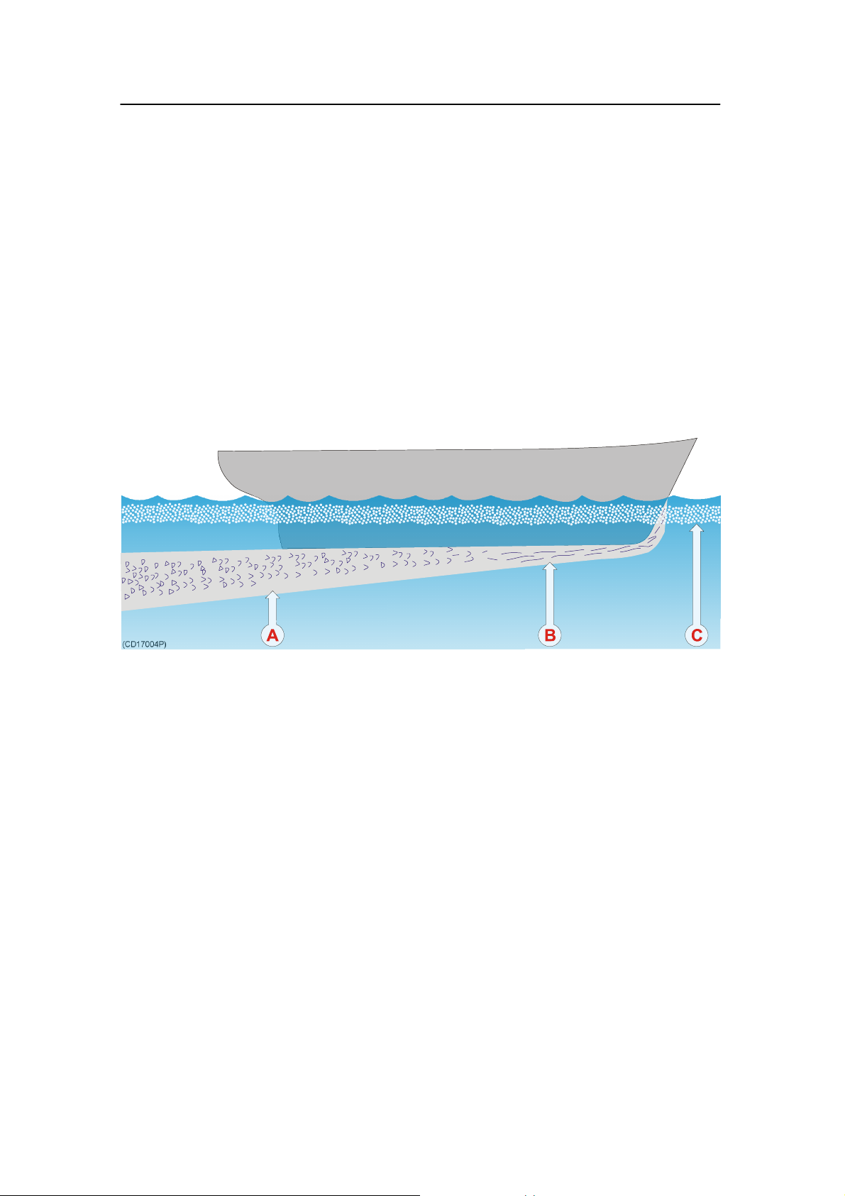
Boundary water layer
When the vessel forces its way through the sea, the friction
between the hull and the water creates a boundary layer. The
thickness of the boundary layer depends upon vessel speed and
the roughness of the hull. Objects protruding from the hull, and
dents in the hull, disturb the flow and increase the thickness of
the boundary layer. The flow in this boundary layer may be
laminar or turbulent. A laminar flow is a nicely ordered, parallel
movement of the water. A turbulent flow has a disorderly
pattern, full of eddies. The boundary layer increases in thickness
when the flow goes from laminar to turbulent. The figure below
illustrates the boundary layer of a vessel moving through the
water.
Boundary water layers:
(A) = Turbulent flow
(B) = Laminar flow
(C) = Air bubbles in the water
Furthermore, air bubbles in the sea water are pressed down
below the hull and mixed into the boundary layer. The boundary
layer is thin underneath the forward part of the vessel, and
increases in thickness as it moves towards aft. If the sides of the
hull are steep, some of the air bubbles in the boundary layer may
escape to the sea surface along the vessel sides. It is our
experience that a wide and flat bottom, with a rising angle less
than around 13 degrees, is prone to giving air problems for the
transducer. In any case a transducer location in the forward part
of the hull is preferred in order to minimise the influence of the
boundary layer.
4
851-165182 / Rev.B
Page 9

Installation manual
Propeller noise
The propulsion propeller is the dominant noise source on most
fishing vessels, research vessels, merchant vessels and pleasure
crafts. The noise is transmitted through the sea water. For this
reason, the transducer should be placed far away from the
propeller, which means on the fore part of the hull. Positions
outside the direct line of sight from the propeller are favourable.
On small vessels with short distances it is advised to mount the
transducer on that side of the keel where the propeller blades
move upwards, because the propeller cavitation is strongest on
the other side. The cavitation starts most easily when the water
flows in the same direction as the propeller blade, and that is to
some degree the case at that side of the keel where the propeller
blades move downwards.
Bow thruster propellers are extremely noisy. When in operation,
the noise and cavitation bubbles make the echo sounder useless,
almost no matter where the transducer is installed. And when
not in operation, the tunnel creates turbulence, and if the vessel
is pitching, the tunnel may be filled with air or aerated water in
the upper position and release this in the lower position.
Therefore, an echo sounder transducer should be placed well
away from the bow thruster.
851-165182 / Rev.B
5
Page 10

Simrad 38/200 Combi C Transducer
Summary and general recommendation
Some of the above guide lines are conflicting, and each case has
to be treated individually in order to find the best compromise.
Generally the propeller noise is the dominant factor, and a
recommended transducer location is in the fore part of the hull,
with maximum distance from the bow equal to one third of the
total length of the hull at the water line.
General recommendation for transducer location:
(A) = Transducer
(B) = Angle 1 - 2 degrees
(L) = Hull length at water line
(M) = Maximum 1/3 of the hull length at water line (L)
If the vessel hull has a bulbous bow, this may well be a good
transducer location, but also here must be taken into
consideration the flow pattern of the aerated water. Often the
foremost part of the bulb is preferable.
6
851-165182 / Rev.B
Page 11

Installation manual
External mounting
This transducer has a streamlined housing, and it is designed for
installation outside the hull.
This transducer is mainly used on smaller vessels. A location
approximately 0.5 m aside from the keel may be adequate for
the passage of water between the keel and the transducer. The
figures illustrate external mounting of transducers on steel hulls
and on wood or polyester hulls respectively.
Inclination of the transducer face
Incline the transducer face approximately 1-2 degrees (D), so
that the flowing water meets it directly. This assures laminar
water flow. Mounting screws must not be extruding from the
transducer, and the space around the screws must be filled with
a compound (C) and/or a locking ring.
Smooth surface
Ensure that the surface of the transducer face, the hull plating
and putty around the transducer is as even and smooth as
possible. Obstructions on these surfaces will create problems
with turbulant flow.
851-165182 / Rev.B
7
Page 12

Simrad 38/200 Combi C Transducer
Steel hull
A fairing (A), made by the shipyard, is placed between the
transducer and the hull. It is required in order to adapt for the
deadrise angle of the hull, and it will also house a cable service
loop (B). The fairing can be made of wood or steel, and should
have the same outline dimensions as the transducer. Remember
to create an air outlet (E) on the fairing, and to fill the bolt holes
with a filling compound to ensure a smooth transducer surface.
(A) = Fairing (1) = Steel conduit
(B) = Cable service loop (2) = Stuffing tube
(C) = Filling compound (3) = Washer
(D) = 1-2 degrees inclination (4) = Rubber gasket
(E) = Air outlet (5) = Packing nipple
(F) = Forward
(I) = Threaded rod with nuts and washers, or bolt
8
851-165182 / Rev.B
Page 13

Installation manual
Wood or polyester hull
A fairing (A), made by the shipyard, is placed between the
transducer and the hull. It is required in order to adapt for the
deadrise angle of the hull, and will also house a cable service
loop (B). The fairing is made from wood, polyester or steel, and
should have the same outline dimensions as the transducer. Use
tarred felt (H) between th fairing and the hull. Remember to
create an air outlet (E) on the fairing, and to fill the bolt holes
with a filling compound to ensure a smooth transducer surface.
851-165182 / Rev.B
(A) = Fairing (1) = Steel conduit
(B) = Cable service loop (2) = Stuffing tube
(C) = Filling compound (3) = Washer
(D) = 1-2 degrees inclination (4) = Rubber gasket
(E) = Air outlet (5) = Packing nipple
(F) = Forward
(G) = Shim (wood)
(H) = Tarred felt
(I) = Threaded rod with nuts and washers
9
Page 14

Simrad 38/200 Combi C Transducer
Flat hull
If the vessel’s hull is flat you do not need a fairing. The
transducer is then be bolted directly to the hull using two bronze
or stainless steel bolts (I) and a cable bushing. Note that the
cable bushing must be mounted with proper gaskets (4) under
and over the hull, as well as sealing compound (J) around the its
body. Also, fill the bolt holes with a filling compound to ensure
a smooth transducer surface.
(C) = Filling compound (3) = Washer
(F) = Forward (4) = Rubber gaskets
(I) = Threaded rod with nuts and washers
(J) = Sealing compound
10
851-165182 / Rev.B
Page 15

Installation manual
Longitudinal angle
On deplacement hulls, the transducer (A) must be mounted in an
angle of 5 to 8 degrees (B) in relation to the keel (C).
With a planing hull, this angle must be 0 degrees.
(A) = Transducer
(B)=5to8°ondeplacementhulls,0°onplaninghulls
(C) = Keel
(F) = Forward
851-165182 / Rev.B
11
Page 16

Simrad 38/200 Combi C Transducer
Cable glands
The transducer cable must pass through the hull using approved
cable glands for the type of vessel in question.
A steel cable gland is normally used on professional vessels
with steel hulls. A bronze cable gland can be delivered as an
option for vessels with wood or fibreglass construction. Vessel
not to be classified can as an option use a cable gland made of
plastic.
Note Simrad strongly recommends that a length of conduit is fitted
around transducer cable glands made of steel or bronze and
extended over the water-line inside the vessel. This precaution
reduces the danger of flooding in the event of gland failure and
transducers installed in this manner are also easier to replace.
Some vessels may experience difficulties finding suitable areas
of the hull for mounting transducer cable glands due to existing
water tanks, concrete ballast or other obstacles. A possible
solution in such cases is to run the transducer cables in a steel
conduit aft along the hull until a suitable cable gland location is
available. The respective cable gland can then be installed as
described in the following instructions.
Note Simrad takes no responsibility for the correct installation of
cable glands, associated hull modifications and/or structural
support of transducer cable penetration. These activities are
subject to individual approval by the respective classification
society for the vessel in question.
Order numbers
Steel hull cable gland kit: 599-202216
Wood/GRP hull cable gland kit: 119-038200
Small vessel cable gland kit: 599-202182
12
851-165182 / Rev.B
Page 17

Installation manual
Cable gland installation for steel hulls
This cable gland kit is designed for steel vessels. It must be
welded to the hull plates.
(A) = Steel conduit
(B) = Stuffing tube, DNV
approved carbon steel st52.3
(C) = Washers, 24 x 8 x 2 mm
(D) = Rubber gasket
(E) = Packing nipple. Make
sure that you do not damage the
transducer cable by tightening
the packing nipple too hard!
(F) = Cable to the echo
sounder (or a junction box)
The gland gland kit includes all
of the necessary parts needed to
install the unit excluding
screws.
Simrad recommends that a one
inch steel conduit (that the
transducer cable will be run
through) with an inside
threaded diameter of
three-quarter inches is welded
to the gland’s stuffing tube. The
conduit must extend to above
the vessel’s water line.
851-165182 / Rev.B
13
Page 18

Simrad 38/200 Combi C Transducer
Gland installation for wood or GRP hulled vessels
A bronze cable gland kit is available for wood and GRP vessels.
(A) = Packing nipple. Make
sure that you do not damage the
transducer cable by tightening
the packing nipple too hard!
(B) = Washers
(C) = Rubber gaskets
(D) = Hole diameter 28 mm
(E) = Steel conduit
(F) = Cable to the echo
sounder (or a junction box)
The gland gland kit includes all
of the necessary parts needed to
install the unit excluding
screws.
Simrad recommends that a one
inch steel conduit (that the
transducer cable will be run
through) with an inside
threaded diameter of
three-quarter inches is attached
to the gland’s packing nipple.
This connection must be
watertight, and the conduit must
extend to above the vessel’s
water line.
14
851-165182 / Rev.B
Page 19

Installation manual
Cable gland installation for smaller vessels
This cable glands made of plastic is designed for those smaller
vessels that do not need to be classified.
(A) = Packing nut (bronze).
Ensure that you do not to
damage the transducer cable by
tightening the packing nut too
hard!
(B) = Rubber gasket
(C) = Plastic disk
(D) = Rubber gasket
(E) = Stuffing tube
(F) = Backing nut (bronze)
(G) = Backing washer (plastic)
(H) = O-ring 42.5 x 3.0 N
(I) = O-ring 39.5 x 3.0 N
(J) = Cable to the echo sounder
(or a junction box)
Stuffing tube hole diameter: 36 mm ±1.5 mm.
Apply ample amount of sealant between the backing washer (H)
and the hull plate.
The cable gland kit contains all the listed parts, except the
sealant.
Note The two O-rings must be clean, in good condition and free of cuts
or other defects which could affect their water-tight integrity.
Splicing
If you need to cut the transducer cable, you must splice it
correctly.
Note DO NOT solder the wires together with only electrical tape for
insulation, as this will result in electrical noise and reduced
operational performance.
To splice the cable, use a metal junction box. The chassis of the
junction box must be grounded, but the cable shielding must
NOT be connected to the junction box ground.
851-165182 / Rev.B
15
Page 20

Simrad 38/200 Combi C Transducer
Cable in steel conduit
It is strongly recommended to lay a steel conduit from the
transducer’s cable gland to the echo sounder transceiver, and to
pull the transducer cable through this conduit. There are two
reasons for this.
• First, it will make it easier at a later stage to replace the
transducer.
• Second, noise and i nterference from other electrical
equipment is greatly reduced.
With a steel conduit the installation will satisfy the EU
regulations for EMC interference. Without a steel conduit, there
is a risk of reduced echo sounder performance.
The steel conduit must be unbroken and watertight from the
transducer to above the water line. From there, the cable can be
pulled further, or a junction box can be installed to facilitate
further connections. Note that the steel conduit must act as a
continuous electrical screen all the way. To ensure proper
shieklding, the conduit must be electrically connected to the
echo sounder transceiver chassis.
Steel conduit dimensions:
• minimum 35 mm inner diameter
• minimum 6 mm wall thickness (4.5 mm if galvanised).
If two or more transducers are installed close to each other it is
possible to pull their cables in the same steel conduit, provided
the conduit diameter is increased accordingly. However, for easy
replacement it is recommended that each transducer has its own
steel conduit.
16
851-165182 / Rev.B
Page 21

Installation manual
Handling and maintenance
Do not lift the transducer by the cable.
Some transducers are delivered with a cover plate on the face
for protection during transport. Let this plate stay on as long as
possible, but do not forget to remove it before the vessel goes
into the sea.
An anti-fouling paint may be applied to the transducer face.
Because some paint types may be aggressive to the polyurethane
in the transducer face, please consult Simrad’s list of approved
paints on the next page.
Note Arctic tanks have acoustic windows made of polycarbonate.
These must neither be painted nor cleaned with chemicals.
During dry docking of the vessel, the transducer face may be
cleaned for shells and other marine fouling. Be careful not to
make cuts in the transducer face. Use a piece of wood or a very
fine grade emery paper.
851-165182 / Rev.B
17
Page 22

Simrad 38/200 Combi C Transducer
Approved anti-fouling paints
This is Simrad’s list of approved antifouling paints on
polyurethane transducer housing.
From Jotun Paints, Sandefjord Norway:
• Antifouling Seamate HB 33
• Antifouling Seamate HB 66
• Antifouling Seamate HB 99
• Racing
• Non-stop
From International Paints:
• Intersleek tie coat + 425 FCS
- BXA386/BXA390/BXA391 Grey
- HKA563/HKA570/HKA571 Yellow
Mix BXA386, BXA390 and BXA391 first, then apply. When
dry, mix HKA563, HKA570 and HKA571, apply.
From Hempel IFA Coatings AS:
• Hempel A/F Classic 76550
From Jotun-Henry Clark Ltd:
• Anti-fouling Seaguardian
Note Refer to the manufacturer’s documentation and data sheets for a
complete procedure.
18
851-165182 / Rev.B
Page 23

Installation manual
DRAWING FILE
The following installation drawings have been included.
Note These drawings are for information and guidance only. They are
not in scale. All dimensions are in mm unless otherwise is noted.
The drawings are available on AutoCad and/or PDF format.
Contact your local Simrad dealer for assistance.
→ Wiring (830-202218), page 20
→ Outline drawing (830-202213), page 21
→ Recommended mounting arrangement (830-201729), page 22
851-165182 / Rev.B
19
Page 24

Simrad 38/200 Combi C Transducer
20
38/200 Combi C - Connections
851-165182 / Rev.B
Page 25

Installation manual
851-165182 / Rev.B
38/200 Combi C - Outline dimensions
21
Page 26

Simrad 38/200 Combi C Transducer
22
38/200 Combi C - Installation - Page 1
851-165182 / Rev.B
Page 27

Installation manual
851-165182 / Rev.B
38/200 Combi C - Installation - Page 2
23
Page 28

E 2005 Simrad AS
ISBN 82-8066-051-8
 Loading...