

Page 1
www.silverlinetools.com
3 Year Guarantee
*Register online within 30
days. Terms & Conditions apply
Garantie de 3 ans
*Enregistrez votre produit en ligne
dans les 30 jours. Sous réserve des
termes et conditions appliquées
3 Jahre Garantie
*Innerhalb von 30 Tagen online
registrieren. Es gelten die Allgemeinen
Geschäftsbedingungen
3 años de garantía
*Registre su producto online durante
los primeros 30 días. Se aplican
términos y condiciones
3 jaar garantie
*Registreer uw product binnen 30
dagen online. Algemene voorwaarden
zijn van toepassing
3 anni di garanzia
*Registrare il vostro prodotto on-line entro
30 giorni. Termini e condizioni si applicano
Page 2

www.silverlinetools.com
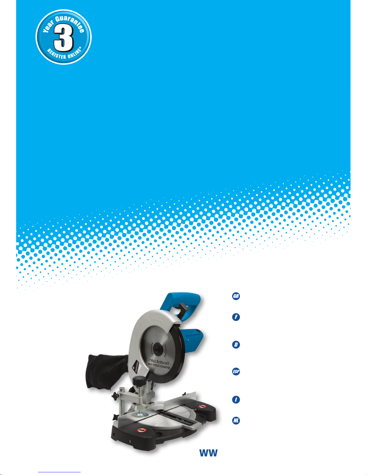
262705
1400W Compound Mitre Saw 210mm
S
I
L
V
E
R
L
I
N
E
R
A
N
G
E
DIY
1400W Compound Mitre Saw 210mm
Scie radiale combinée 1400 W
1400-W-Kapp- und Gehrungssäge, 210 mm
1400W Sierra ingletadora 210 mm
1400W Troncatrice Composta 210 mm
1400 W verstekzaag, 210 mm
Page 3
2
2
1
6
8
3
4
7
5
9
10
11
13
15
16
18
17
22
23
24
25
26
27
I
II
III
12
14
19
20
21
28
29
30
32 31
33
34
35
36
37
38
Page 4

www.silverlinetools.com
3
English .................. 4
Français ................ 10
Deutsch ................. 16
Español ................. 22
Italiano .................. 28
Nederlands ............ 34
®
S
I
L
V
E
R
L
I
N
E
R
A
N
G
E
DIY
1400W Compound Mitre Saw 210mm
Page 5
4
GB
Original Instructions
WARNING: Always wear ear protection where the sound level exceeds 85dB(A) and limit the time
of exposure if necessary. If sound levels are uncomfortable, even with ear protection, stop using
the tool immediately and check the ear protection is correctly fitted and provides the correct level
of sound attenuation for the level of sound produced by your tool.
WARNING: User exposure to tool vibration can result in loss of sense of touch, numbness,
tingling and reduced ability to grip. Long term exposure can lead to a chronic condition. If
necessary, limit the length of time exposed to vibration and use anti-vibration gloves. Do not
operate the tool with hands below a normal comfortable temperature, as vibration will have a
greater effect. Use the figures provided in the specification relating to vibration to calculate the
duration and frequency of operating the tool.
Sound and vibration levels in the specification are determined according to EN60745 or
similar international standards. The figures represent normal use for the tool in normal
working conditions. A poorly maintained, incorrectly assembled, or misused tool, may produce
increased levels of noise and vibration. www.osha.europa.eu provides information on sound
and vibration levels in the workplace that may be useful to domestic users who use tools for
long periods of time.
General Safety
WARNING Read all safety warnings and all instructions. Failure to follow the warnings and
instructions may result in electric shock, fire and/or serious injury.
WARNING: This appliance is not intended for use by persons (including children) with
reduced, physical or mental capabilities or lack of experience or knowledge unless
they have been given supervision or instruction concerning use of the appliance by a
person responsible for their safety. Children must be supervised to ensure that they do not
play with the appliance.
Save all warnings and instructions for future reference.
Specification
Voltage: ....................................................................230-240V~ 50Hz
Power: ..................................................................... 1400W
No load speed: ......................................................... 5000min-1
Max depth of cut: ..................................................... 50mm
Max blade size: ........................................................ Ø210mm
Bore: ........................................................................ Ø25.4mm (1")
Supplied blade: ........................................................ Ø210 x Ø25.4 x
2.8mm x 24T
Mitre table angles: ................................................... 0° to 45°
left & right
Bevel cuts: ............................................................... 0° to 45° left
Straight cut:
0° x 0°: ................................................................... 120mm x 50mm
Mitre cut:
45° (L&R) x 0°: ........................................................ 80mm x 50mm
Bevel cut:
0° x 45° (L): ............................................................. 120mm x 30mm
Compound mitre cut:
45° (L) x 45° (R): ...................................................... 80mm x 30mm
45° (L) x 45° (L): ...................................................... 80mm x 30mm
Ingress protection: ................................................... IP20
Power cord length: ................................................... 2.0 m
Protection class: ......................................................
Weight: .................................................................... 6kg
Sound and vibration information:
Sound pressure LPA: ................................................. 89dB(A)
Sound power LWA: .................................................... 102dB(A)
Uncertainty K: .......................................................... 3dB
Weighted vibration ah(main handle): ......................... 6.0m/s2
Uncertainty K: .......................................................... 1.5m/s2
The sound intensity level for the operator may exceed 85dB(A) and sound protection
measures are necessary.
As part of our ongoing product development, specifications of Silverline products may
alter without notice.
Description of Symbols
The rating plate on your tool may show symbols. These represent important information about
the product or instructions on its use.
Wear hearing protection
Wear eye protection
Wear breathing protection
Wear head protection
Wear hand protection
Read instruction manual
Toxic fumes or gases!
Caution!
Class II construction (double insulated for additional protection)
Conforms to relevant legislation and safety standards
Environmental Protection
Waste electrical products should not be disposed of with household waste.
Please recycle where facilities exist. Check with your local authority or retailer
for recycling advice
V
Volts
~
Alternating current
A
Ampere
n
o
No load speed
Hz
Hertz
W, kW
Watt, kilowatt
/min or min-1
(revolutions or reciprocation)
per minute
Page 6

www.silverlinetools.com
5
262705 1400W Compound Mitre Saw 210mm
The term "power tool" in the warnings refers to your mains-operated (corded) power tool or
battery-operated (cordless) power tool.
Work Area Safety
a) Keep work area clean and well lit. Cluttered or dark areas invite accidents
b) Do not operate power tools in explosive atmospheres, such as in the
presence of flammable liquids, gases or dust. Power tools create sparks which may
ignite the dust or fumes
c) Keep children and bystanders away while operating a power tool. Distractions can
cause you to lose control
Electrical Safety
a) Power tool plugs must match the outlet. Never modify the plug in any way. Do not
use any adapter plugs with earthed (grounded) power tools. Unmodified plugs and
matching outlets will reduce risk of electric shock
b) Avoid body contact with earthed or grounded surfaces, such as pipes, radiators,
ranges and refrigerators. There is an increased risk of electric shock if your body is
earthed or grounded
c) Do not expose power tools to rain or wet conditions. Water entering a power tool
will increase the risk of electric shock
d) Do not abuse the cord. Never use the cord for carrying, pulling or unplugging the
power tool. Keep cord away from heat, oil, sharp edges or moving parts. Damaged
or entangled cords increase the risk of electric shock
e) When operating a power tool outdoors, use an extension cord suitable for outdoor
use. Use of a cord suitable for outdoor use reduces the risk of electric shock
f) If operating a power tool in a damp location is unavoidable, use a residual current
device (RCD) protected supply. Use of an RCD reduces the risk of electric shock
Personal Safety
a) Stay alert, watch what you are doing and use common sense when operating a power
tool. Do not use a power tool while you are tired or under the influence of drugs, alcohol
or medication. A moment of inattention while operating power tools may result in serious
personal injury
b) Use personal protective equipment. Always wear eye protection. Protective
equipment such as dust mask, non-skid safety shoes, hard hat, or hearing protection used
for appropriate conditions will reduce personal injuries
c) Prevent unintentional starting. Ensure the switch is in the off-position before
connecting to power source and/or battery pack, picking up or carrying the tool.
Carrying power tools with your finger on the switch or energising power tools that have
the switch on invites accidents
d) Remove any adjusting key or wrench before turning the power tool on. A wrench or
a key left attached to a rotating part of the power tool may result in personal injury
e) Do not overreach. Keep proper footing and balance at all times. This enables better
control of the power tool in unexpected situations
f) Dress properly. Do not wear loose clothing or jewellery. Keep your hair, clothing and
gloves away from moving parts. Loose clothes, jewellery or long hair can be caught in
moving parts
g) If devices are provided for the connection of dust extraction and collection
facilities, ensure these are connected and properly used. Use of dust collection can
reduce dust-related hazards
Power Tool Use & Care
a) Do not force the power tool. Use the correct power tool for your
application. The correct power tool will do the job better and safer at the rate for which it
was designed
b) Do not use the power tool if the switch does not turn it on and off. Any power tool
that cannot be controlled with the switch is dangerous and must be repaired
c) Disconnect the plug from the power source and/or the battery
pack from the power tool before making any adjustments, changing
accessories, or storing power tools. Such preventive safety measures reduce the risk of
starting the power tool accidentally
d) Store idle power tools out of the reach of children and do not allow persons
unfamiliar with the power tool or these instructions to operate the power tool.
Power tools are dangerous in the hands of untrained users
e) Maintain power tools. Check for misalignment or binding of moving parts, breakage
of parts and any other condition that may affect the power tool’s operation. If
damaged, have the power tool repaired before use. Many accidents are caused by
poorly maintained power tools
f) Keep cutting tools sharp and clean. Properly maintained cutting tools with sharp cutting
edges are less likely to bind and are easier to control
g) Use the power tool, accessories and tool bits etc. in accordance with these
instructions, taking into account the working conditions and the work to be
performed. Use of the power tool for operations different from those intended could result
in a hazardous situation
WARNING: When used in Australia or New Zealand, it is recommended that this tool is ALWAYS
supplied via Residual Current Device (RCD) with a rated residual current of 30mA or less.
Service
a) Have your power tool serviced by a qualified repair person using only identical
replacement parts. This will ensure that the safety of the power tool is maintained
Circular Saw Safety
WARNING: Before connecting a tool to a power source (mains switch power point receptacle,
outlet, etc.) be sure that the voltage supply is the same as that specified on the nameplate of
the tool. A power source with a voltage greater than that specified for the tool can result in
serious injury to the user, and damage to the tool. If in doubt, do not plug in the tool. Using a
power source with a voltage less than the nameplate rating is harmful to the motor.
a) Do not allow anyone under the age of 18 years to operate this saw
b) When operating the saw, use safety equipment including safety goggles or shield, ear
protection, dust mask and protective clothing including safety gloves
c) Hand-held power tools may produce vibration. Vibration can cause disease. Gloves may help
to maintain good blood circulation in the fingers. Hand-held tools should not be used for long
periods without a break
d) Always use recommended blades with correct size and shape of arbor holes e.g.
diamond or round. Blades that do not match the mounting hardware of the saw will run
eccentrically, causing loss of control
e) Whenever possible, use a vacuum dust extraction system to control dust/waste
f) Power tools must always be held by the insulated gripping surfaces when performing
an operation, ensuring protection if the cutting tool makes contact with its own cord or
hidden wiring. Contact with a ‘live’ wire will make exposed metal parts of the power tool
‘live’ and shock the operator if the insulated gripping surfaces are not used
g) Ensure hands are kept away from the cutting area and blade. Keep one hand on the
auxiliary handle or motor housing. If both hands are holding the tool they cannot be cut by
the blade
h) Do not attempt to cut material thicker than detailed in the Specifications section of this
manual
i) Adjust the cutting depth to the thickness of the workpiece i.e. less than a full tooth of the
blade should be visible below the workpiece
j) Ensure that work is correctly supported. Large panels may sag under their own weight
and bind the saw blade. Supports must be placed under the panel on both sides, close to
the line of cut and near the edge of the panel
k) Ensure all supports and power cables are completely clear of the cutting path
l) Always secure the workpiece to a stable platform, ensuring body exposure is minimised,
avoiding blade binding, or loss of control
m) For accuracy of cut, and to avoid blade binding, always use a rip fence or straight edge
guide
n) Never hold a workpiece in your hand or across your legs whilst cutting
o) Always stand at an angle to the tool when operating
p) Be aware that the blade will project from the underside of the workpiece
q) Do not reach beneath the workpiece where the guard cannot protect you from the blade
r) Note the direction of rotation of the motor and the blade
s) Inspect the workpiece and remove all nails and other embedded objects prior to starting
work
t) Do not apply any sideways or twisting force to the blade whilst cutting
u) If a cut does not extend to the edge of the workpiece, or if the blade binds in the cut, allow
the blade to come to a complete stop and lift the saw out of the workpiece
v) Do not attempt to free a jammed blade before first disconnecting the machine from power
w) Do not move the saw backwards at any time whilst cutting
x) Beware of projected waste. In some situations, waste material may be projected at speed
from the cutting tool. It is the user’s responsibility to ensure that other people in the work
area are protected from the possibility of projected waste
y) If you are interrupted when operating the saw, complete the process and switch off before
diverting your attention
z) The blade bolt and washers were specially designed for your saw. For optimum
performance and safety of operation never use damaged or incorrect bolt/blade washers
aa) Check the lower guard for proper closing before each use. Do not operate the saw if the
lower guard does not move freely and close instantly. Never clamp or tie the lower guard into
the open position. If the saw is accidentally dropped, the lower guard may be bent. Raise the
lower guard with the retracting handle and make sure it moves freely and does not touch the
blade or any other part, in all angles and depths of cut
bb) Always observe that the lower guard is covering the blade before resting the saw on a
surface after use. An unprotected, coasting blade will cause the saw to move backwards,
cutting whatever is in its path. Be aware of the time it takes for the blade to stop after the
trigger switch is released
cc) Periodically check that all nuts, bolts and other fixings have not loosened, tighten where
necessary
The tool must be used only for its prescribed purpose. Any use other than those mentioned in
this manual will be considered a case of misuse. The user, and not the manufacturer, shall be
liable for any damage or injury resulting from such cases of misuse.
The manufacturer shall not be liable for any modifications made to the tool nor for any damage
resulting from such modifications.
Even when the tool is used as prescribed it is not possible to eliminate all residual risk factors.
Page 7

Original Instructions
6
GB
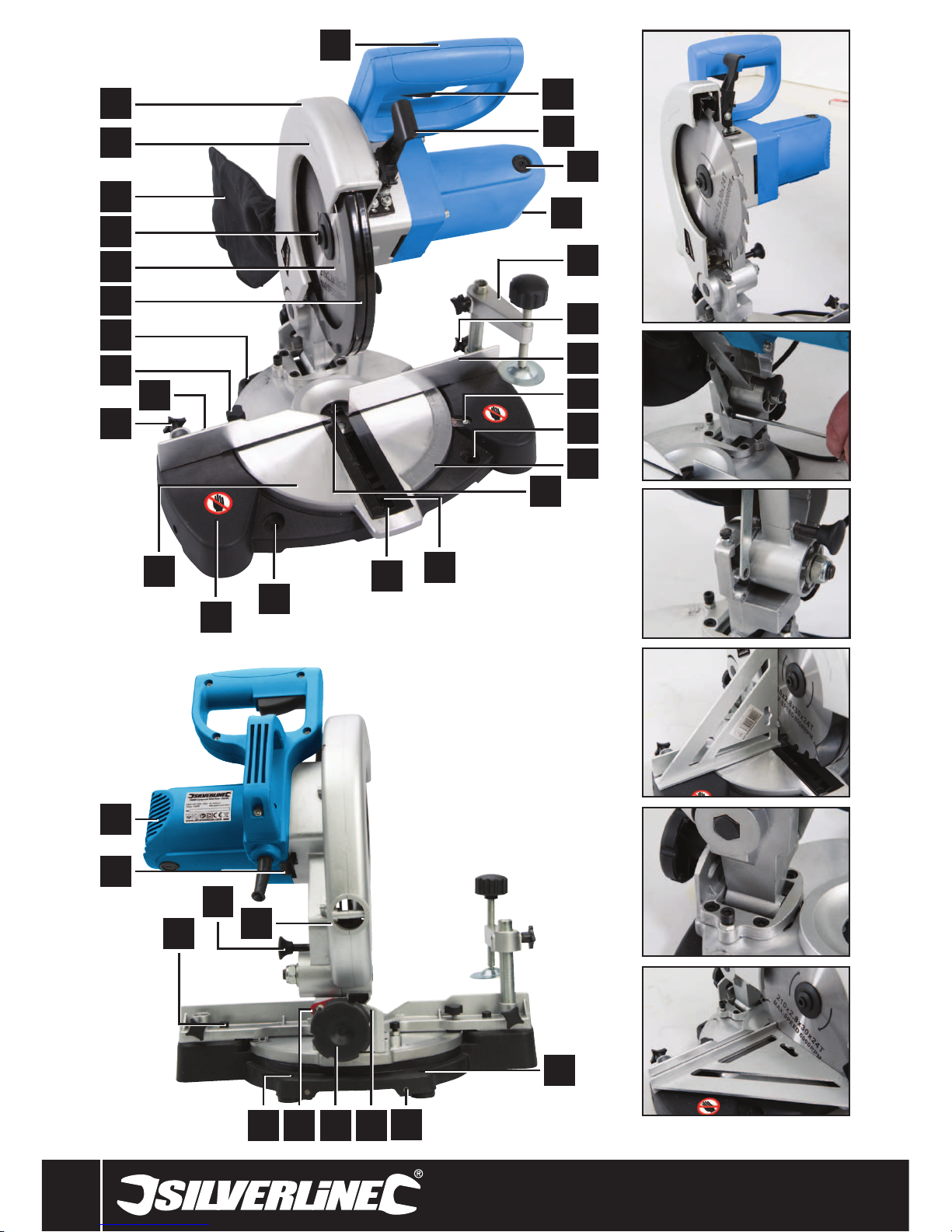
1 Operating Handle
2 On/Off Trigger Switch
3 Release Lever
4 Brush Access Cover
5 Motor Vents
6 Clamp
7 Clamp Mounting (R)
8 Fence
9 Mitre Angle Indicator
10 Bench Mounting Hole
11 Mitre Angle Gauge
12 Table Insert Screw
13 Blade Channel
14 Table Insert (kerf plate)
15 Bench Mounting Hole
16 Base
17 Mitre Base
18 Clamp Mounting (L)
19 Fence Bolt (L)
20 Mitre Angle Locking Knob
21 Bench Mounting Hole
22 Rotating Blade Guard
23 Saw Blade
24 Blade Securing Bolt
25 Dust Bag
26 Rotation Indicator
27 Fixed Blade Guard
28 Bench Mounting Hole
29 Stabiliser Mounting Holes
30 Bevel Angle Gauge
31 Bevel Angle Locking Knob
32 Bevel Angle Indicator
33 Bench Mounting Hole
34 Dust Port
35 Fence Bolt (R)
36 Latching Pin
37 Spindle Lock
38 Carrying Handle
Product Familiarisation
Accessories (not shown):
• Hex Key (x2)
• Rear Stabiliser
• Rear Stabiliser Fittings
Intended Use
• Mains powered portable or bench-mounted power tool for cutting through wood and other
materials. Straight, bevel, mitre and compound (mitre+bevel) cuts. The included saw blade
is suitable for wood and man-made composite wood materials.
Unpacking Your Tool
• Carefully unpack and inspect your new tool. Familiarise yourself with all its features and
functions
• Ensure that all parts of the tool are present and in good condition. If any parts are missing
or damaged, have such parts replaced before attempting to use this tool
Before Use
WARNING: Ensure the tool is disconnected from the power supply before attaching or
changing any accessories, or making any adjustments.
Bench mounting
IMPORTANT: It is recommended to mount the saw to a bench or board. Although the saw can
be used without mounting to a bench or board there is a greater safety risk in use.
• Mount the saw to a level, horizontal bench or work table using bolts, washers and locking
nuts (not supplied) through the Bench Mounting Holes (10, 15, 21 & 28)
• DO NOT over-tighten or the base may cracked and damaged, or use bolts that are not a
good fit for the Bench Mounting Holes
• Alternatively, mount the saw on 13mm or thicker board, and clamp the board to the work
support; this makes it easy to re-locate the saw, clamping it to a work support wherever
needed
• When using a board it may be necessary to countersink the washers and nuts so the board
is level on the surface it is used on
CAUTION: Make sure the mounting surface is not warped as an uneven surface can cause
binding and inaccurate sawing
Fitting the rear stabiliser
• When the saw is not fitted to a bench or board, always fit the rear stabiliser into the two
Stabiliser Mounting Holes (29). The stabiliser helps prevent the saw from tipping in use. Use
the fittings provided to attach the stabiliser
Dust Extraction
• The Dust Bag (25) fits over the Dust Port (34). For most efficient operation, empty the dust
bag when it is no more than half full; this allows better air flow through the bag
• Optimal dust extraction is achieved by connecting a dust extraction system or vacuum
cleaner to the Dust Port. A third party adapter may be required.
Transportation
• When transporting the saw, only use the Carrying Handle (38) if the saw is detached from
a board or bench and no material is clamped to the base. When the saw is mounted to
another surface, move by holding the board or bench only and keep the tool upright. The
saw can be stored and transported with the cutting head lowered and secured by the
Latching Pin (36); however there is a small risk that vibration in transit could cause the
Latching Pin to move allowing the cutting head to rise
Fitting and removing the blade
WARNING: Never attempt to use a blade larger than the stated capacity of the saw, as it might
come into contact with the blade guards. Never use a blade that is too thick to allow the outer
blade washer to engage with the flats on the spindle; it will prevent the blade screw from
properly securing the blade on the spindle. Do not use the saw to cut metal or masonry unless
the saw blade is specifically designed for that material. Ensure any spacers and spindle rings
that may be required suit the spindle and the blade fitted.
WARNING: Never fit and use a blade that is visibly damaged, deformed or has dull or missing
teeth.
WARNING: Never fit and use a blade made from high speed steel (HSS).
IMPORTANT: Wear gloves when handling blades.
IMPORTANT: Even if the blade is pre-fitted, if this is the first use of the tool always check the
blade is securely fitted before use.
1. Ensure the cutting head is in its upper position
2. Disconnect the lower guard operating arm by removing the rotating blade guard screw
(Image I & II)
3. Press the Release Lever (3) and move the Rotating Blade Guard (22) up and into the
Fixed Blade Guard (27) (Image III)
4. Press the Spindle Lock and rotate the blade until the spindle locks
5. Use the supplied Hex Key to remove the Blade Securing Bolt (24) and blade flange
6. The mounting has a LH thread so rotate the hex key clockwise to unscrew the bolt
7. Move the saw blade to the left slightly to clear the mounting and remove from the
Fixed Blade Guard
Page 8

www.silverlinetools.com
7
262705 1400W Compound Mitre Saw 210mm
8. Check the saw blade that will be fitted to ensure it is not heavily worn, bent or damaged
and no teeth are missing
9. Check the arrow marking of the blade matches the Rotation Indicator (26). The teeth
must point down towards the workpiece
10. Check the blade mounting is clean and clear of swarf and dust and fit the blade into the
recess of the Fixed Blade Guard and onto the blade mounting
11. Press the Spindle Lock and re-fit the blade flange and Blade Securing Bolt and tighten
securely anti-clockwise without over-tightening. Do not leave the hex key in the bolt
after tightening
12. Rotate the Rotating Blade Guard back over the blade and re-fit the blade guard screw to
the lower guard operating arm (Image II & I)
13. Check the normal operation of the Rotating Blade Guard by pressing the Release Lever
and moving the cutting head up and down with the Operating Handle
14. Re-connect to mains power and run the saw for a short time to make sure the blade is
rotating and operating correctly
Operation
WARNING: ALWAYS wear eye protection, adequate respiratory and hearing protection, as well
as suitable gloves, when working with this tool.
Adjusting the mitre angle
The Mitre Angle Locking Knob (20) is used to lock the table at the desired mitre angle. The
mitre saw cuts from 0° to 45° both left and right. To adjust the mitre angle:
1. Loosen the Mitre Angle Locking Knob
2. Rotate the mitre angle with the Operating Handle (1) to the desired position using the
Mitre Angle Indicator (9) and Mitre Angle Gauge (11). The mitre table features positive
click stops at 0, 5, 10, 15, 22.5, 30, 35, 40 and 45° both left and right for quick setting of
common mitre angles
3. Retighten the Mitre Angle Locking Knob to lock the angle setting
WARNING: Be sure to tighten the Mitre Angle Locking Knob before making a cut. Failure to do
so could result in the table moving during the cut and cause serious personal injury.
Adjusting the bevel angle
The Bevel Angle Locking Knob (31) is used to set the blade at the desired bevel angle. The
mitre saw bevel cuts from 0° to 45° to the left only. To adjust the bevel angle:
1. Ensure the Mitre Angle Locking Knob (20) is tight
2. Loosen the Bevel Angle Locking Knob (31)
3. Tilt the cutting head with the Carrying Handle (38)
4. Use the Bevel Angle Indicator (32) and Bevel Angle Gauge (30) to set the correct angle
5. Retighten the Bevel Angle Locking Knob to secure in position
WARNING: Be sure to tighten the Bevel Angle Locking Knob before making a cut. Failure to do
so could result in the saw arm moving during the cut and cause serious personal injury.
Switching on and off
• To turn the saw on, depress and hold the On/Off Trigger Switch (2)
• To turn the saw off, release the On/Off trigger switch
Making a cut
• A compound mitre cut involves using a mitre angle and a bevel angle at the same time.
It is used to make picture frames, cut mouldings, make boxes with sloping sides, and for
roof framing
• Always make a test cut on a piece of scrap wood before cutting the workpiece.
1. Pull on the Release Lever (3) and lift the cutting head to its full height
2. Loosen the Mitre Angle Locking Knob (20)
3. Rotate the Mitre Base (17) until the Mitre Angle Indicator (9) aligns with the desired
angle on the Mitre Angle Gauge (11)
4. Retighten the Mitre Angle Locking Knob
WARNING: Be sure to tighten the Mitre Angle Locking Knob before making a cut. Failure to
do so could result in the table moving during the cut, causing serious personal injury.
5. Loosen the Bevel Angle Locking Knob (31) and move the cutting head to the left or right
to the desired bevel angle (between 0° and 45°). Tighten the Bevel Angle Locking Knob
6. Place the workpiece flat on the table with one edge securely against the Fence (8). If the
board is warped, place the convex side against the fence. If the concave side is placed
against the fence, the board could break and jam the blade
7. When cutting long pieces of timber, support the opposite end of the timber with a roller
stand or a work surface that is level with the saw table
8. Use the Clamp (6) to secure the workpiece wherever possible. NOTE: It is possible to
remove the Clamp by loosening the Clamp Mounting (7 & 18) and moving it to the other
side of the table. Make sure the Clamp Mounting is tight before using the Clamp
9. Before turning on the saw, perform a dry run of the cutting operation to check that there
are no problems
10. Hold the Operating Handle (1) firmly and squeeze the On/Off Trigger Switch (2). Allow
the blade to reach maximum speed
11. Press the Release Lever (3) and slowly lower the blade into and through the workpiece
12. Release the On/Off Trigger Switch and allow the saw blade to stop rotating before
raising the blade out of the workpiece. Wait until the blade stops before removing
the workpiece
Accessories
• A range of accessories and consumables, including saw blades, additional clamps and
personal protective equipment, is available from your Silverline stockist. Spare parts can be
obtained from toolsparesonline.com
Maintenance
WARNING: ALWAYS disconnect from the power supply before carrying out any inspection,
maintenance or cleaning.
Bevel Angle 0° Adjustment
Checking angle
1. Loosen the Bevel Angle Locking Knob (31) and position the cutting head at the maximum
height with the Bevel Angle Indicator at 0° on the Bevel Angle Gauge (30). Tighten the
Bevel Angle Locking Knob
2. Lower the cutting head so the exposed blade is in the Blade Channel (13) and lock in
this position with the Latching Pin (36)
3. Recheck that the cutting head is upright and the Bevel Angle Indicator is still at 0°
4. Place a set square on the table with one short edge against the Mitre Base (17) and the
other short edge against the blade (avoiding the TCT tips) - see Image IV
Note: If the blade is not square with the Mitre Base, adjustment is required
Changing angle
1. There are two Hex Bolts at the base of the cutting head section (the left bolt is indicated
on Image V). These allow adjustment to move the cutting head assembly to tilt to the
right or left so the blade vertical angle will change
2. Turn the thin nut (locking nut) on the required bolt thread so it is at a higher position, and
make a small adjustment to the bolt with the provided hex key (the adjustment should
be very small).
3. Re-tighten the thin nut
4. You may need to adjust the bevel angle by loosening the Bevel Angle Locking Knob so
you can move the cutting head to the left to access the bolt you need
5. Return the cutting head to its upright position and recheck the angular alignment against
the square
6. Repeat the above steps until a 90° angle is achieved
7. Tighten the Bevel Angle Locking Knob
8. A minor adjustment can be made with the Bevel Angle Indicator (32) so it is set to 0°
when the set square is at a 90° angle (Image IV)
Mitre Angle 0°Adjustment
The major adjustment of the mitre angle 0° position is achieved by altering the Fence (8)
position
1. Loosen the Mitre Angle Locking Knob (20)
2. Rotate the mitre angle with the Operating Handle (1) to the desired 0° position using the
Mitre Angle Indicator (9) and Mitre Angle Gauge (11)
3. Retighten the Mitre Angle Locking Knob to lock the angle setting
4. Lower the cutting head so the exposed blade is in the Blade Channel (13) and lock in
this position with the Latching Pin (36)
5. Use a set square to check the 90° angle between the Fence (8) and the Saw Blade (23) -
see Image VI
6. Adjust the position of the Fence by loosening Fence Bolt (L) (19) and Fence Bolt (R) (35)
so the Fence is at exactly 90° using the set square
7. Re-tighten the two Fence Bolts
8. Re-check that the Mitre Angle Indicator is still at 0°. A very minor adjustment can
be made of the Mitre Angle Indicator by loosening the screw and making a small
adjustment to the indicator direction
9. Release the Latching Pin and allow the cutting head to return to its top position
Replacing the Table Insert
IMPORTANT: If the table insert is damaged or heavily worn, it must be replaced to ensure safe
operation of the tool.
1. To replace the Table Insert (14) loosen the Fence Bolt (L) (19) and unscrew and remove
Fence Bolt (R)(35) and angle the Fence (8) away from the Table Insert. Unscrew the
Table Insert Screw (12) and remove the Table Insert
2. Clean the Blade Channel (13) and fit the new Table Insert. Refit and tighten the Table
Insert Screw
3. Move the Fence back to the correct position and refit the Fence Bolt (R). Ensure the
Fence is at the correct angle with a square before tightening the two Fence Bolts
4. To ensure the fence is at the right angle, with the tool powered off, bring down the blade
and use a square to make sure the blade and fence are at exactly 90°
Page 9

Original Instructions
8
GB
Problem Possible cause Solution
No operation
Plug fuse Replace fuse
Worn brushes Have brushes replaced by an authorised Silverline service centre
Power tool fault Contact an authorised Silverline service centre
Cutting performance poor
Teeth worn or damaged Replace blade
Incorrect saw blade type Replace blade with correct type for material being sawed
Incorrect blade specification Ensure blade meets the required blade specification for this mitre saw
Incorrectly fitted blade Remove blade and refit exactly as per the instructions in this manual
Power tool vibrating excessively
in use
Saw blade distorted, bent or damaged Replace blade immediately
Saw blade incorrectly mounted Re-fit blade exactly as per the instructions in this manual
Machine fault Contact an authorised GMC service centre
Mitre or Bevel angle difficult to adjust Build-up of sawdust Vacuum up sawdust
Troubleshooting
General inspection
• Regularly check that all the fixing screws are tight
• Inspect the supply cord of the tool, prior to each use, for damage or wear. Repairs should be
carried out by an authorised Silverline service centre. This advice also applies to extension
cords used with this tool
Cleaning
• Keep your tool clean at all times. Dirt and dust will cause internal parts to wear quickly, and
shorten the machine’s service life. Clean the body of your machine with a soft brush, or dry
cloth. If available, use clean, dry, compressed air to blow through the ventilation holes
• Clean the tool casing with a soft damp cloth using a mild detergent. Do not use alcohol,
petrol or strong cleaning agents
• Never use caustic agents to clean plastic parts
Lubrication
• Slightly lubricate all moving parts at regular intervals with a suitable spray lubricant
Brushes
• Over time the carbon brushes inside the motor may become worn
• Excessively worn brushes may cause loss of power, intermittent failure, or visible sparking
• To replace the brushes, remove the brush access plugs from both sides of the machine.
Remove the worn brushes and replaced with new. Replace brush access plugs.
Alternatively, have the machine serviced at an authorised service centre
Storage
• The cutting head can be lowered and secured by the Latching Pin (36) to make the saw
a smaller size for storage. Store this tool carefully in a secure, dry place out of the reach
of children
Disposal
Always adhere to national regulations when disposing of power tools that are no longer
functional and are not viable for repair.
• Do not dispose of power tools, or other waste electrical and electronic equipment (WEEE),
with household waste
• Contact your local waste disposal authority for information on the correct way to dispose
of power tools
Page 10

www.silverlinetools.com
9
262705 1400W Compound Mitre Saw 210mm
Silverline Tools Guarantee
Notified body: Intertek Testing Services, Shanghai.
The technical documentation is kept by: Silverline Tools
Date: 27/06/14
Signed:
Mr Darrell Morris
Managing Director
Name and address of the manufacturer:
Powerbox International Limited, Company No. 06897059. Registered address:
Central House, Church Street, Yeovil, Somerset BA20 1HH,
United Kingdom.
Terms & Conditions
Silverline Tools Guarantee
This Silverline product comes with a 3 year guarantee
Register this product at www.silverlinetools.com within 30 days of purchase in order
to qualify for the 3 year guarantee. Guarantee period begins according to the date of
purchase on your sales receipt.
Registering your purchase
Registration is made at silverlinetools.com by selecting the Guarantee Registration
button. You will need to enter:-
• Your personal details
• Details of the product and purchase information
Once this information is entered your guarantee certificate will be created in PDF
format for you to print out and keep with your purchase.
Guarantee period becomes effective from the date of retail purchase as detailed on
your sales receipt.
PLEASE KEEP YOUR SALES RECEIPT
If this product develops a fault within 30 days of purchase, return it to the stockist
where it was purchased, with your receipt, stating details of the fault. You will
receive a replacement or refund.
If this product develops a fault after the 30 day period, return it to:
Silverline Tools Service Centre
PO Box 2988
Yeovil
BA21 1WU, UK
The guarantee claim must be submitted during the guarantee period.
You must provide the original sales receipt indicating the purchase date, your name,
address and place of purchase before any work can be
carried out.
You must provide precise details of the fault requiring correction.
Claims made within the guarantee period will be verified by Silverline Tools to
establish if the deficiencies are related to material or manufacturing of the product.
Carriage will not be refunded. Items for return must be in a suitably clean and safe
state for repair, and should be packaged carefully to prevent damage or injury
during transportation. We may reject unsuitable or
unsafe deliveries.
All work will be carried out by Silverline Tools or its authorized
repair agents.
The repair or replacement of the product will not extend the period
of guarantee
Defects recognised by us as being covered by the guarantee shall be corrected
by means of repair of the tool, free of charge (excluding carriage charges) or by
replacement with a tool in perfect working order.
Retained tools, or parts, for which a replacement has been issued, will become the
property of Silverline Tools.
The repair or replacement of your product under guarantee provides benefits which
are additional to and do not affect your statutory rights as a consumer.
What is covered:
The repair of the product, if it can be verified to the satisfaction of Silverline Tools
that the deficiencies were due to faulty materials or workmanship within the
guarantee period.
If any part is no longer available or out of manufacture, Silverline Tools will replace it
with a functional replacement part.
Use of this product in the EU.
What is not covered:
Silverline Tools does not guarantee repairs required as a result of:
Normal wear and tear caused by use in accordance with the operating instructions
eg blades, brushes, belts, bulbs, batteries etc.
The replacement of any provided accessories drill bits, blades, sanding sheets,
cutting discs and other related items.
Accidental damage, faults caused by negligent use or care, misuse, neglect,
careless operation or handling of the product.
Use of the product for anything other than normal domestic purposes.
Change or modification of the product in any way.
Use of parts and accessories which are not genuine Silverline Tools components.
Faulty installation (except installed by Silverline Tools).
Repairs or alterations carried out by parties other than Silverline Tools or its
authorized repair agents.
Claims other than the right to correction of faults on the tool named in these
guarantee conditions are not covered by the guarantee.
Battery Guarantee
Silverline batteries are guaranteed for 30 days. If a defect occurs on a registered
battery during the term of the Battery Guarantee, due to material or manufacturing
fault, then Silverline will replace it free of charge. This guarantee does not apply to
commercial use nor does it extend to normal wear and tear or damage as a result of
accident, abuse or misuse.
CE Declaration of Conformity
The undersigned: Mr Darrell Morris
as authorised by: Silverline Tools
Declares that
Identification code: 262705
Description: 1400W Compound Mitre Saw 210mm
Conforms to the following directives and standards:
• Machinery Directive 2006/42/EC
• Low Voltage Directive 2006/95/EC
• EMC Directive 2004/108/EC
• RoHS Directive 2011/65/EU
• EN61029-2-9:2009, EN61029-1:2009+A11:2010, EN60825-1:2007
• EN55014-1:2006/+A1:2009+A2:2011, EN55014-2:1997/+A1:2001/+A2:2008
• EN61000-3-2:2006/+A1:2009/+A2:2009, EN61000-3-3:2008
Page 11

10
F
Traductions des instructions originales
Attention : Toujours porter des protections sonores lorsque le niveau d’intensité est supérieur
à 85 dB(A) et limiter le temps d’exposition si nécessaire. Si l’intensité sonore devient
inconfortable, même avec les protections, arrêter immédiatement d’utiliser l’appareil, vérifier
que les protections soient bien mises et qu’elles soient adéquates avec le niveau sonore
produit par l’appareil.
Attention : L’exposition de l’utilisateur aux vibrations peut engendrer une perte du toucher,
des engourdissements, des picotements et ainsi réduire la capacité de préhension. De longues
expositions peuvent également provoquer ces symptômes de façon chronique. Si nécessaire,
limiter le temps d’exposition aux vibrations, et porter des gants anti-vibrations. Ne pas utiliser
cet appareil avec vos mains sous des conditions en dessous de températures normales, car
l’effet vibratoire en est accentué. Se référer au cas de figures des caractéristiques relatives
aux vibrations pour calculer le temps et fréquence d’utilisation de l’appareil.
Les niveaux sonores et vibratoires des caractéristiques techniques sont déterminés en fonction
de la norme EN60745 ou autres normes internationales. Ces données correspondent à un
usage normale de l’appareil, et ce dans des conditions de travail normales. Un appareil mal
entretenu, mal assemblé ou mal utilisé peut augmenter les niveaux sonores et vibratoires. Pour
plus d’informations sur la directive des émissions sonores et vibratoires, visitez le site http://
osha.europa.eu/fr.
Consignes générales de sécurité
AVERTISSEMENT Veuillez lire l’intégralité des consignes de sécurité et des instructions.
Le non-respect de ces consignes et instructions peut entraîner un risque de choc électrique,
d’incendie et/ou se traduire par des blessures graves
Attention : Cet appareil n’est pas conçu pour être utilisé par des personnes (enfants compris)
ayant des capacités physiques ou mentales réduites, ou n’ayant pas la connaissance ou
l’expérience requise, à moins d’être sous la supervision d’une personne responsable de leur
sécurité ou d’avoir reçu les instructions nécessaires. Les enfants ne doivent pas s’approcher
et jouer avec cet appareil.
Sécurité sur la zone de travail
a) Maintenir une zone de travail propre et bien éclairée. Des zones encombrées et mal
éclairées sont sources d’accidents.
Description des symboles
La plaque signalétique figurant sur votre outil peut présenter des symboles. Ces symboles
constituent des informations importantes relatives au produit ou des instructions concernant
son utilisation.
Port de protection auditive
Port de lunettes de sécurité
Port du masque respiratoire
Port du casque
Port de gants
Lire le manuel d’instructions
Emanation d'échappement ou de gaz !
Attention!
Construction de classe II (Double isolation pour une protection supplémentaire)
Conforme à la réglementation et aux normes de sécurité pertinentes
Protection de l’environnement
Les produits électriques usagés ne doivent pas être jetés avec les ordures
ménagères. Veuillez les recycler dans les centres prévus à cet effet. Pour
de plus amples informations, veuillez contacter votre municipalité ou point
de vente.
V Volts
~ Courant alternatif
A Ampère
n
o
Vitesse à vide
Hz Hertz
W, kW Watt, kilowatt
/min or min-1 tour par minute
Caractéristiques techniques
Tension : .................................................................. 230-240 V~ 50 Hz
Puissance : .............................................................. 1400 W
Vitesse à vide : ......................................................... 5000 min
-1
Profondeur de coupe max. : ..................................... 50 mm
Taille de lame max. : ................................................ Ø 210 mm
Alésage : .................................................................. Ø 25,4 mm
Lame fournie : ......................................................... Ø210 x Ø25,4 x
2,8 mm x 24 dents
Coupes d’onglet : ..................................................... 0° à 45° gauche
et droite
Coupes biseautées : ................................................. 0° à 45° gauche
Coupe droite : .......................................................... 120 mm x 50 mm
Coupe d’onglet à 45° (G et D) x 0° : ......................... 80 mm x 50 mm
Coupe biseauté à 0° x 45° (G) :................................ 120 mm x 30 mm
Coupe combinée :
45°(G) x 45°(R) : ...................................................... 80 mm x 30 mm
5°(G) x 45°(G) : ........................................................ 80 mm x 30 mm
Indice de protection : ............................................... IP20
Longueur du câble d’alimentation : .......................... 2,0 m
Classe de protection : ..............................................
Poids : ...................................................................... 6 kg
Informations sur le niveau d’intensité sonore et vibratoire :
Pression acoustique LPA :..........................................89 dB(A)
Puissance acoustique LWA : ...................................... 102 dB(A)
Incertitude K : .......................................................... 3 dB
Vibration pondérée ah (poignée principale) : ............. 6,0 m/s
2
Incertitude K : .......................................................... 1,5 m/s2
L’intensité sonore peut dépasser 85 dB(A) et il est recommandé que l’opérateur
prenne des mesures de protection sonore.
Du fait de l’évolution constante de nos produits, les caractéristiques des produits
Silverline peuvent changer sans notification préalable.
Page 12

www.silverlinetools.com
11
262705 Scie radiale combinée 1400 W
b) Ne pas utiliser d’outils électriques dans des environnements explosifs, tels
qu’à proximité de liquides, de gaz ou de poussières inflammables. Les appareils
électriques produisent des étincelles susceptibles d’enflammer la poussière ou les
vapeurs présentes.
c) Eloigner les enfants et les passants pendant l’utilisation d’un appareil électrique.
Ceux-ci peuvent provoquer une perte d’attention et faire perdre la maîtrise de l’appareil.
Sécurité électrique
a) La prise d’un appareil électrique doit être adaptée à la prise du secteur. Ne jamais
modifier la prise en aucune façon. Ne jamais utiliser d’adaptateur sur la prise
électrique d’appareil mis à la terre. Des prises non modifiées, adaptées aux boîtiers de
prise de courant, réduiront le risque de décharge électrique.
b) Eviter le contact corporel avec les surfaces mises à la terre telles que tuyaux,
radiateurs, cuisinières et réfrigérateurs. Le risque de décharge électrique est plus
important si le corps est mis à la terre.
c) Ne pas exposer l’appareil électrique à la pluie ou à l’humidité. L’infiltration d’eau dans
un appareil électrique accroît le risque de décharge électrique.
d) Ne pas maltraiter le cordon électrique. Ne jamais utiliser le cordon électrique pour
porter, tirer ou débrancher l’appareil. Protéger le cordon électrique de la chaleur, du
contact avec l’essence, des bords tranchants et pièces rotatives. Un cordon électrique
endommagé ou entortillé accroît le risque de décharge électrique.
e) Lors d’une utilisation de l’appareil électrique en extérieur, se servir d’une rallonge
appropriée à une utilisation en extérieur. Cela réduit le risque de décharge électrique.
f) Si une utilisation de l’appareil électrique dans un environnement humide ne peut être
évitée, utiliser une alimentation protégée par un disjoncteur différentiel. L’utilisation
d’un disjoncteur différentiel réduit le risque de décharge électrique.
Sécurité des personnes
a) Rester vigilant et faire preuve de bon sens lors de la manipulation de l’appareil. Ne pas
utiliser un appareil électrique lorsque l’on se trouve dans un état de fatigue, ou sous
l’influence de drogues, d’alcool ou de médicaments. Un moment d’inattention pendant
l’utilisation d’un outil électrique peut se traduire par des blessures graves.
b) Porter un équipement de protection approprié. Toujours porter une protection
oculaire. Le port de masque à poussières, chaussures de sécurité antidérapantes, casque
de sécurité et protections antibruit adaptés aux différentes conditions de travail réduit le
risque de blessures corporelles.
c) Eviter tout démarrage accidentel. S’assurer que l’interrupteur marche-arrêt soit en
position d’arrêt avant de brancher l’appareil sur l’alimentation secteur ou d’installer
la batterie, de prendre l’appareil ou de le transporter. Porter un appareil électrique tout en
maintenant le doigt posé sur l’interrupteur ou brancher un appareil électrique dont l’interrupteur
est sur la position de marche est source d’accidents.
d) Enlever toute clé et tout instrument de réglage avant de mettre l’appareil électrique
en marche. Une clé ou un instrument de réglage laissé fixé à un élément en rotation de
l’appareil électrique peut entraîner des blessures physiques.
e) Ne pas essayer d’atteindre une zone hors de portée. Se tenir toujours en position
stable permettant de conserver l’équilibre. Cela permet de mieux contrôler l’appareil
électrique dans des situations inattendues.
f) Porter des vêtements appropriés. Ne pas porter de vêtements amples ou des bijoux
pendants. Eloigner cheveux, vêtements et gants des pièces en mouvement. Les
vêtements amples, les bijoux pendants et cheveux longs peuvent être happés par les pièces en
rotation.
g) Si l’appareil est pourvu de dispositifs destinés au raccord d’équipements d’extraction
et de récupération de la poussière/sciure, s’assurer qu’ils soient bien fixés et utilisés
correctement L’utilisation de ces dispositifs peut réduire les risques dus à la poussière.
Utilisation et entretien des appareils électriques
a) Ne pas forcer sur l’appareil électrique. Utiliser l’appareil électrique approprié au
travail à effectuer. Un appareil électrique adapté et employé au rythme pour lequel il a été
conçu permettra de réaliser un travail de meilleure qualité et dans de meilleures conditions
de sécurité.
b) Ne pas utiliser un appareil électrique dont l’interrupteur marche-arrêt est hors
service. Tout appareil électrique dont la commande ne s’effectue plus par l’interrupteur
marche-arrêt est dangereux et doit être réparé.
c) Débrancher l’appareil électrique ou démonter sa batterie avant d’effectuer tout
réglage ou changement d’accessoire et avant de le ranger. De telles mesures
préventives réduiront les risques de démarrage accidentel.
d) Ranger les appareils électriques inutilisés hors de portée des enfants et ne
pas permettre l’utilisation de cet appareil aux personnes non habituées à son
maniement ou n’ayant pas lu les présentes instructions. Les appareils électriques
sont dangereux dans les mains d’utilisateurs inexpérimentés.
e) Veiller à l’entretien des appareils électriques. Vérifier que les éléments rotatifs soient
bien alignés et non grippés. S’assurer de l’absence de pièces cassées ou endommagées
susceptibles de nuire au bon fonctionnement de l'appareil. Si l’appareil électrique est
endommagé, le faire réparer avant toute utilisation. De nombreux accidents sont dus à
l’utilisation d’appareils électriques mal entretenus.
f) Veiller à ce que les outils de coupe soient tenus affûtés et propres. Des outils de coupe
bien entretenus, aux tranchants bien affûtés, sont moins susceptibles de se gripper et sont
plus faciles à contrôler.
g) Utiliser l’appareil électrique, les accessoires et outils à monter conformément à ces
instructions, en tenant compte des conditions de travail et de la tâche à réaliser.
Toute utilisation d’un appareil électrique autre que celle pour laquelle il a été conçu peut
entraîner des situations à risque.
ATTENTION : Lorsque utilisé en Australie ou en Nouvelle Zélande, il est recommandé que cet
appareil soit toujours alimenté via un disjoncteur différentiel ayant un courant résiduel de 30
mA ou moins.
Révision
a) Ne faire réparer votre appareil électrique que par un réparateur qualifié utilisant
uniquement des pièces de rechange identiques. Cela permet de maintenir la sécurité
d’utilisation de l’appareil électrique.
Consignes de sécurité relatives
aux scies circulaires
AVERTISSEMENT : Avant de brancher l’outil sur l’alimentation secteur, vérifiez bien que la
tension d’alimentation soit la même que celle indiquée sur la plaque signalétique de l’outil.
Une alimentation électrique dont la tension est supérieure à celle indiquée sur l’outil risque
d’entraîner des blessures chez l’utilisateur et des dommages sur l’outil. En cas de doute, ne
branchez pas l’outil. L’utilisation d’une source de courant dont la tension est inférieure à celle
indiquée sur l’outil peut endommager le moteur.
a) Il est interdit à toute personne de moins de 18 ans d’employer cet appareil.
b) L’utilisation d’une scie circulaire demande le port d’équipements de sécurité tels que
lunettes ou visière de sécurité, casque anti-bruit et habillement protecteur tel que gants
de sécurité.
c) Les outils électriques portatifs produisent des vibrations. Les vibrations peuvent provoquer
des maladies. En conservant la chaleur, des gants portés par l’utilisateur peuvent lui
permettre de maintenir une bonne circulation sanguine dans les doigts. Les outils portatifs
ne doivent pas être utilisés pendant de longues périodes sans marquer une pause.
d) Utilisez toujours les lames recommandées, de la taille indiquée et de l’alésage indiqué.
Les lames non adaptées aux éléments de montage prévus sur la scie présenteront des
défauts de concentricité et conduiront à une mauvaise maîtrise de la machine.
e) Dans la mesure du possible, utilisez un système d’extraction des poussières pour
contrôler la poussière/les déchets.
f) En fonctionnement, les outils électriques doivent toujours être tenus par les surfaces de
préhension isolantes, ce qui garantit votre protection en cas de contact entre l’appareil
et son cordon d’alimentation ou des fils électriques cachés. Tout contact entre un fil sous
tension et les parties métalliques apparentes de l’appareil peut entraîner un risque de choc
électrique si l’utilisateur vient à toucher ces parties métalliques.
g) Gardez toujours les mains à distance de la zone de coupe et de la lame. En tenant l’outil
à deux mains, la lame ne risque pas de vous blesser. Tenez d’une main la poignée
principale, de l’autre la poignée secondaire ou le carter du moteur.
h) Ne tentez pas de couper des matériaux plus épais que ceux recommandés dans ce manuel.
i) Adaptez la profondeur de coupe en fonction de l’épaisseur de la pièce à couper, c’est-à-
dire que la lame ne doit ressortir sous la pièce à couper que sur une longueur inférieure à
la taille d’une dent.
j) Assurez-vous que la pièce à couper se trouve sur des supports adéquats. Les grosses
pièces peuvent ployer sous leur propre poids et ainsi coincer la lame. Les panneaux et
pièces de grande taille doivent être soutenus de manière adéquate de chaque côté de la
ligne de coupe, bien à proximité de celle-ci, ainsi que sur les bords.
k) Assurez-vous que tous les supports et les câbles électriques se trouvent en dehors du
trait de coupe.
l) Immobilisez toujours la pièce à couper sur une surface stable à l’aide d’instruments vous
laissant libre de vos mouvements, en les plaçant de manière qu’ils n’entraînent pas le
grippage de la lame ou la perte du contrôle de la machine.
m) Pour des coupes de précision, et pour empêcher le grippage de la lame, utilisez toujours
un guide de coupe.
n) Ne tenez jamais la pièce à couper dans la main ou en vous servant de votre jambe
comme point d’appui lors de la coupe.
o) Ne vous placez jamais dans l’axe de la lame lors du maniement de l’appareil.
p) Tenez compte du fait que la lame ressortira par dessous la pièce à couper.
q) Ne placez pas vos doigts sous la pièce à couper car le carter de protection de lame ne
permettrait plus de vous en protéger.
r) Tenez compte du sens de rotation du moteur et de la lame.
s) Examinez préalablement la pièce à couper et retirez les clous et autres objets étrangers.
t) N’appliquez jamais de force latérale ou de torsion sur la lame lors de la coupe.
u) Si la coupe entreprise ne doit pas parvenir jusqu’au bord de la pièce à couper, ou si la
lame se grippe en cours de coupe, laissez-la lame s’arrêter complètement avant de lever
la scie.
v) Ne commencez jamais à dégager une lame coincée avant d’avoir bien débranché la
machine.
w) Ne jamais faire reculer la scie lors de la coupe.
x) Attention aux projections de débris. Dans certaines circonstances, des éclats de matériau
peuvent se trouver projetés à grande vitesse. Il appartient à l’utilisateur de s’assurer
que toute personne également présente dans la zone de travail soit protégée contre ces
projections.
y) Si l’on vous interrompt durant la coupe, finissez l’action entreprise et éteignez bien la
machine avant de lever les yeux de l’ouvrage.
z) Le boulon ainsi que les rondelles de montage de la lame ont été spécialement conçus
pour cette scie. Pour préserver les performances et le bon fonctionnement de la machine,
n’utilisez jamais de boulons et rondelles abîmés ou inadaptés.
Page 13

Traductions des instructions originales
12
F
aa) Inspectez régulièrement le carter de protection de la lame. Si le carter ne revient pas
automatiquement sur la lame, faites réviser l’appareil avant toute utilisation. N’utilisez
jamais un dispositif quelconque pour maintenir le carter de protection de la lame en
position ouverte. Si vous faites tomber la scie, le carter de protection peut être tordu.
Soulevez le carter de protection à l’aide du levier du carter de protection et assurez-vous
qu’il peut se déplacer librement et ne touche pas la lame ou une autre pièce, à tous les
angles et toutes les profondeurs de coupe.
bb) Vérifiez toujours que le carter de protection recouvre la lame avant de poser la scie sur
une surface après utilisation. Une lame en mouvement qui n’est pas protégée par le
carter de protection déplacera la scie vers l’arrière, coupant tout ce qui se trouve sur son
passage. Soyez conscient que la lame de la scie reste n mouvement pendant un certain
temps après que la gâchette marche-arrêt ait été relâchée.
cc) Vérifiez régulièrement que toutes les fixations par écrous, boulons et autres soient bien
serrées.
L’outil doit être uniquement utilisé dans son but prescrit. Toute autre utilisation que celle
indiquée dans le présent manuel sera considérée impropre. Tout dommage et toute lésion
découlant d’une quelconque utilisation impropre de l’outil relèveront de la responsabilité de
l’utilisateur et non pas de celle du fabricant.
Le fabricant ne saurait être responsable d’aucune modification apportée à l’outil ni d’aucun
dommage résultant de telles modifications.
Même lorsque l’outil est utilisé comme indiqué, il est impossible d’éliminer tous les facteurs
de risques résiduels
Accessoires (non illustrés)
• 2 clé à six pans
• Stabilisateur arrière
• Fixations du stabilisateur arrière
Usage conforme
• Appareil électroportatif portable ou à monter sur établi pour couper le bois et d’autres
matériaux. Coupes droites, d’onglet, biseautées ou combinées (à onglet +biseau). La scie
inclue est compatible pour le bois et le bois composite.
Déballage
• Déballez le produit avec soin. Veillez à retirer tout le matériau d’emballage et familiarisez-
vous avec toutes les caractéristiques du produit.
• Si des pièces sont endommagées ou manquantes, faites-les réparer ou remplacer avant
d’utiliser l’appareil.
Avant utilisation
ATTENTION : Assurez-vous que l’appareil soit débranché de sa source d’alimentation avant
d’installer ou changer d’accessoire, ou faire des réglages.
Montage sur établi
IMPORTANT : Il est recommandé de monter la scie sur un établi ou sur une planche. Bien que
la scie puisse être utilisée sans être montées sur un établi ou une planche, il y a un plus grand
risque d’utilisation.
• Montez la scie sur un établi ou une planche de niveau et horizontal en utilisant des écrous
autobloquants et des rondelles (non fournis) à travers les trous de montage sur établi (10,
15, 21 et 28).
• Ne serrez pas excessivement car le socle pourrait se fissurer et s’endommager, ou n’utilisez
pas des écrous qui ne sont pas de la bonne dimension pour les trous de montage sur établi.
• Autrement, montez la scie sur une planche de 13 mm d’épaisseur ou plus, et fixez la
planche sur le support de travail ; ceci facilite le déplacement de la scie, en la fixant sur un
support de travail là où vous en avez besoin.
• Lorsque vous utilisez une planche il peut être nécessaire de fraiser les rondelles et les
écrous pour que la planche soit de niveau sur la surface sur laquelle elle est utilisée.
ATTENTION : Assurez-vous que la surface de montage soit plane, car une surface irrégulière
peut provoquer un grippage des pièces ou un sciage imprécis.
Assembler le stabilisateur arrière.
• Lorsque la scie n’est pas fixée sur un établi, insérez toujours le stabilisateur arrière dans
les trous de montage su stabilisateur (29). Ce stabilisateur permet d’éviter que la scie ne
s’incline vers l’arrière pendant l’utilisation. Utilisez les fixations fournies pour attacher le
stabilisateur.
Extraction de la poussière
• Le sac à poussière (25) s’attache sur la tubulure d’extraction de la poussière(34). Pour un
fonctionnement plus efficace, videz le sac à poussière avant qu’il ne soit à moitié plein ;
Ceci permet une meilleure circulation d’air dans le sac.
• Une extraction de la poussière optimale est obtenue en branchant un système d’extraction
de la poussière ou un aspirateur sur la tubulure d’extraction de la poussière. Un adaptateur
tiers peut être nécessaire.
Transport
• Pour transporter la scie, utilisez uniquement la poignée de transport (38) si la scie est
détachée d’une planche ou d’un établi, et qu’aucun matériau ne soit attaché sur le
socle. Lorsque la scie est montée sur une autre surface, déplacez-vous en maintenant
seulement la planche ou l’établi, et gardez l’appareil bien droit. La scie peut être rangée et
transportez avec la tête de coupe abaissée et sécurisée avec la goupille de verrouillage
(36) ; cependant il existe un petit risque de vibration qui peut faire bouger la goupille de
verrouillage et permettre que la tête de coupe s’élève.
1 Poignée de fonctionnement
2 Gâchette de mise en marche/arrêt
3 Levier de relâche
4 Cache des balais de charbon
5 Events du moteur
6 Dispositif de serrage
7 Dispositif de serrage de montage (D)
8 Guide
9 Indicateur d’angle des coupes d’onglet
10 Trou de montage sur établi
11 Echelle de coupes d’onglet
12 Vis d’insert de plateau
13 Passage de la lame
14 Insert de plateau (plaque du trait de coupe)
15 Trou de montage sur établi
16 Socle
17 Plateau des coupes d’onglet
18 Dispositif de serrage de montage (G)
19 Boulon du guide (G)
20 Molette de blocage des coupes d’onglet
21 Trou de montage sur établi
22 Carter de protection pivotant de la lame
23 Lame de scie
24 Boulon de fixation de la lame
25 Sac à poussière
26 Indicateur de rotation
27 Carter de protection fixe
28 Trou de montage sur établi
29 Trous d montage du stabilisateur
Se familiariser avec le produit
30 Echelle de l’angle de biseau
31 Molette de blocage de l’angle de biseau
32 Indicateur de l’angle de biseau
33 Trou de montage sur établi
34 Tubulure d’extraction de la poussière
35 Boulon du guide (D)
36 Goupille de verrouillage
37 Blocage de l’arbre
38 Poignée de transport
Page 14

www.silverlinetools.com
13
262705 Scie radiale combinée 1400 W
Assembler et retirer la lame
ATTENTION : N’essayez jamais d’utiliser une lame avec des capacités plus grandes que
celles indiquées pour la scie, car elle pourrait venir en contact avec les carters de protections.
N’utilisez jamais une lame qui trop épaisse pour permettre à la rondelle extérieure de la lame
de s’engager sur l’arbre ; cela empêchera la vis de la lame de fixer correctement la lame sur
l’arbre. N’utilisez pas la scie pour couper du métal ou des matériaux de maçonnerie, à moins
que la lame de la scie soit spécifiquement conçue pour ces matériaux. Assurez-vous que
toutes les entretoises et les bagues de l’arbre qui peuvent être nécessaires, soient compatibles
avec l’arbre et la lame installée.
ATTENTION : N’installez et n’utilisez jamais une lame qui est visiblement endommagée,
déformée, émoussée ou avec des dents manquantes.
ATTENTION : N’installez et n’utilisez jamais une lame fabriquée à partir d’acier rapide.
IMPORTANT : Portez des gants lorsque vous manipulez les lames.
IMPORTANT : Même si la lame et préinstallée, et s’il s’agit de la première utilisation de la scie,
vérifiez toujours que la lame soit bien fixée avant utilisation.
1. Assurez-vous que la tête de coupe soit dans sa position la plus haute.
2. Enlevez le carter de protection du bras de fonctionnement en retirant la vis carter de
protection pivotant de la lame.(Image I et II).
3. Appuyez sur le bouton de relâche (3) et soulevez le carter de protection pivotant de la
lame (22) vers le carter de protection fixe (27) (Image III).
4. Appuyez le blocage de l’arbre et faites tourner la lame jusqu’à ce que l’arbre se bloque.
5. Utilisez la clé à six pans fournie pour retirer l’écrou de fixation de la lame (24) et la bride.
6. Le support de montage possède un filetage à gauche donc faites tourner la clé à six
pans dans le sens horaire pour dévisser l’écrou.
7. Bougez la lame légèrement vers la gauche pour libérer le support de montage et
l’enlever du carter de protection fixe.
8. Vérifiez que la lame qui va être installée ne soit pas fortement usée, pliée, endommagée
et qu’aucune dent ne soit manquante.
9. Vérifiez que la flèche indiquée sur le disque corresponde avec l’indicateur de rotation
(26). Les dents doivent être dirigées vers la pièce de travail.
10. Vérifiez que le support de montage de la lame soit propre et sans copaux ni poussière,
et placez la lame dans l’encastrement du carter de protection fixe et sur le support de
montage.
11. Appuyez sur le verrouillage de l’arbre et replacez la bride de la lame et l’écrou de
fixation de la lame et serrez dans le sens antihoraire sans serrer excessivement. Ne
laissez pas la clé à six pans dans l’écrou après avoir serré.
12. Faites pivoter le carter de protection pivotant de la lame par-dessus la lame et replacez
la vis du carter de protection de la lame sur le carter de protection inférieur du bras de
fonctionnement (Image II et I)
13. Vérifiez le bon fonctionnement du carter de protection pivotant de la lame en appuyant
sur le levier de relâche et en faisant monter et descendre la tête de coupe avec la
poignée de fonctionnement.
14. Rebranchez sur la source d’alimentation et faites fonctionner la scie pendant une courte
période pour s’assurer que la lame tourne et fonctionne correctement.
Instructions d’utilisation
ATTENTION : Portez toujours des protections oculaires, des protections respiratoires et auditives
adéquates, ainsi que des gants appropriés lorsque vous travaillez avec cette appareil.
Réglage de l’angle des coupes d’onglet
La molette de blocage de l’angle des coupes d’onglet (20) est utilisée pour bloquer le plateau à
l’angle des coupes d’onglet désiré. La scie peut couper de 0° à 45° à gauche et à droite. Pour
régler l’angle des coupes d’onglet :
1. Desserrez la molette de blocage de l’angle des coupes d’onglet
2. Faites tourner l’angle des coupes d’onglet avec la poignée de fonctionnement (1) sur la
position désirée en utilisant l’indicateur de l’angle des coupes d’onglet (9) et l’échelle
des coupes d’onglet (11). Le plateau des coupes d’onglet possède des clics d’arrêt à
0, 5, 10, 15, 22.5, 30, 35, 40 et 45° à gauche et à droite pour des réglages rapides des
coupes d’onglet les plus communes.
3. Resserrez la molette de blocage de l’angle des coupes d’onglet à l’angle réglé.
ATTENTION : Assurez-vous de serrer la molette de blocage de l’angle des coupes d’onglet
avant d’effectuer une coupe. Ne pas suivre cette procédure pourrait entrainer que le plateau
bouge pendant la coupe et provoquer des blessures graves sur l’utilisateur.
Réglage de l’angle de biseau
La molette de l’angle de biseau (31) est utilisée pour régler la lame avec un angle de biseau
voulu. Cette scie radiale effectue des coupes biseautées de 0° à 45° à gauche uniquement.
Pour régler l’angle de biseau :
1. Assurez-vous que la molette de blocage de l’angle des coupes d’onglet (20) soit serrée.
2. Desserrez la molette de l’angle de biseau (31).
3. Inclinez la tête de coupe avec la poignée de transport (38)
4. Utilisez l’indicateur de l’angle de biseau (32) et l’échelle de l’angle de biseau (30) pour
régler correctement l’angle de biseau souhaité.
5. Resserrez la molette de l’angle de biseau pour sécuriser la position
ATTENTION : Assurez-vous de bien serrer la molette de l’angle de biseau avant d’effectuer une
coupe. Ne pas suivre cette procédure pourrait entrainer que le plateau bouge pendant la coupe
et provoquer des blessures graves sur l’utilisateur.
Mise en marche/arrêt
1. Pour mettre la scie en marche, appuyez et restez appuyer sur la gâchette de mise en
marche/arrêt (2)
2. Pour arrêter la scie, relâchez la gâchette de mise en marche/arrêt.
Effectuer une coupe
• Une scie radiale combinée permet d’utiliser un angle de coupe d’onglet avec un angle
de biseau en même temps. Cette fonctionnalité permet de réaliser des cadres photo, des
moulures, des boîtes avec des faces inclinées, et des charpentes de toit.
• Effectuez toujours un test sur une chute de bois avant d’effectuer une coupe sur une
pièce de travail.
1. Tirez sur le levier de relâche (3) et soulevez la tête de coupe jusqu’à sa position la plus
haute.
2. Desserrez la molette de blocage de l’angle des coupes d’onglet (20).
3. Faites tourner le plateau des coupes d’onglet (17) jusqu’à ce que l’indicateur de l’angle
des coupes d’onglet (9) soit aligné avec l’angle désiré sur l’échelle de l’angle des coupes
d’onglet (11).
4. Resserrez la molette de blocage de l’angle des coupes d’onglet.
ATTENTION : Assurez-vous de serrer la molette de blocage de l’angle des coupes d’onglet
avant d’effectuer une coupe. Ne pas suivre cette procédure pourrait entrainer que le plateau
bouge pendant la coupe et provoquer des blessures graves sur l’utilisateur.
5. Desserrez la molette de l’angle de biseau (31) et inclinez la tête de coupe vers la gauche
à l’angle de biseau souhaité (entre 0° et 45°). Serrez la molette de l’angle de biseau.
6. Placez la pièce de travail à plat sur le plateau avec un des côtés bien apposé contre le
guide (8). Si le bois est gauchi, placez la partie convexe contre le guide. Si l’on plaçait la
partie concave contre le guide, le bois pourrait se casser et coincer la lame
7. Pour couper des longues pièces de bois, soutenez l’extrémité opposée du bois avec des
servantes ou un plan de travail se trouvant au même niveau que la table de la scie.
8. Utilisez le dispositif de serrage (6) pour immobiliser la pièce de travail où cela est
possible. Remarque : Il est possible d’enlever le dispositif de serrage en enlevant le
dispositif de serrage de montage (7 et 18), et de le déplacer de l’autre côté du plateau.
Assurez-vous que le dispositif de serrage de montage soit bien serré avant d’utiliser le
dispositif de serrage (6).
9. Avant de mettre la scie en marche, effectuez une coupe-test pour vérifier qu’il n’y a
aucun problème
10. Tenez fermement la poignée de fonctionnement (1) et appuyez sur la gâchette de mise
en marche/arrêt(2). Laissez la lame atteindre sa vitesse maximale.
11. Appuyez sur le levier de relâche (3) et abaissez lentement la lame sur et à travers la
pièce de travail.
12. Relâchez la gâchette de mise en marche/arrêt et laissez la lame de la scie s’arrêter de
tourner avant relever la lame de la pièce de travail. Attendez que la lame s’arrête avant
d’enlever la pièce de travail.
Accessoires
• Toute une gamme d’accessoires et de consommables, tels que des lames de scies, des
dispositifs de serrage supplémentaires et des équipements de protection individuelle, est
disponible depuis votre revendeur Silverline. Des pièces de rechange peuvent être obtenues
depuis www.toolsparesonline.com.
Entretien
ATTENTION : Débranchez TOUJOURS l’appareil de sa source d’alimentation avant tout
nettoyage ou entretien.
Réglage de l’angle de biseau à 0°
Vérification de l’angle
1. Desserrez la molette de l’angle de biseau (31) et placez la tête de coupe dans sa
position la plus haute avec l’indicateur de l’angle de biseau à 0° sur l’échelle de l’angle
de biseau (30). Serrez la molette de l’angle de biseau.
2. Abaissez la tête de coupe de sorte que la lame exposée se trouve dans le passage de la
lame (13) et verrouiller cette position avec la goupille de verrouillage (36).
3. Revérifier que la tête de coupe soit droite et que l’indicateur de l’angle de biseau soit
toujours à 0°.
4. Placez une équerre sur le plateau avec un côté court contre le plateau de coupe d’onglet
(17) et l’autre côté court contre la lame (évitez les lames à pointe TCT). Voir image IV.
Remarque : Si la lame n’est pas perpendiculaire avec le plateau de coupe d’onglet, un réglage
est nécessaire.
Changement de l’angle
1. Il y a deux boulons à six pans sur la base de la section de la tête de coupe (l’écrou
gauche est indiqué sur l’Image V). Ils nécessitent d’être réglés pour déplacer l’ensemble
de la tête de coupe pour l’incliner à gauche ou à droite et ainsi changer l’angle verticale
de la lame.
2. Tournez l’écrou fin (écrou autobloquant) sur le filetage du boulon requis pour qu’il soit
dans une position plus haute, et faite un petit réglage sur l’écrou avec la clé à six pans
fournie (le réglage doit être très fin).
3. Resserrez l’écrou fin.
4. Vous pouvez avoir besoin de régler l’angle de biseau en desserrant la molette de l’angle
de biseau pour vous puissiez déplacer la tête de coupe vers la gauche pour accéder au
boulon dont vous avez besoin.
Page 15

Traductions des instructions originales
14
F
5. Remettez la tête de coupe dans sa position droite et revérifier l’alignement angulaire
contre l’équerre.
6. Refaites les étapes ci-dessus jusqu’à atteindre un angle de 90°.
7. Serrez la molette de l’angle de biseau
8. Un léger réglage peut être effectué avec l’indicateur de l’angle de biseau (32) pour qu’il
soit réglé à 0° lorsque l’équerre indique le réglage à 90° (Image IV).
Angle de coupe d’onglet à 0°
Le réglage important de l’angle de coupe d’onglet à 0° s’effectue en modifiant la position
du guide (8)
1. Desserrez la molette de blocage de l’angle de coupe d’onglet (20).
2. Faites tourner l’angle de coupe d’onglet avec la poignée de fonctionnement (1) sur
la position désirée à 0° en utilisant l’indicateur de l’angle de coupe d’onglet (9) avec
l’échelle de l’angle de coupe d’onglet (11).
3. Resserrez la molette de blocage de l’angle de coupe d’onglet pour verrouiller le réglage
de l’angle.
4. Abaissez la tête de coupe de sorte que la lame exposée se trouve dans le passage de la
lame (13) et verrouillez cette position avec la goupille de verrouillage (36).
5. Utilisez l’équerre pour vérifier l’angle de 90° entre le guide (8) et la lame de scie (23)voir Image IV.
6. Réglez la position du guide en desserrant les boulons du guide gauche (19) et droit (35)
de sorte que le guide soit exactement à 90° en utilisant l’équerre.
7. Resserrez les deux boulons du guide.
8. Revérifiez que l’indicateur de l’angle de coupe d’onglet soit toujours à 0°. Un petit
réglage de l’indicateur de l’angle de coupe d’onglet peut être effectué en desserrant la
vis afin de légèrement ajuster sa direction.
9. Relâchez la goupille de verrouillage et laissez la tête de coupe revenir dans sa position
la plus haute.
Remplacement de l’insert de plateau.
IMPORTANT : Si l’insert de plateau est endommagé ou fortement usé, il doit être remplacé
pour assurer un fonctionnement sûr de l’appareil.
1. Pour remplacer l’insert de plateau (14) desserrez le boulon gauche du guide (19) et
dévissez et enlevez le boulon droit du guide (35) et donnez un angle au guide pour
l’éloigner de l’insert de plateau. Dévissez la vis de l’insert de plateau (12) et enlevez
l’insert de plateau.
2. Nettoyez le passage de la lame (13) et installez le nouvel insert de plateau. Remettez la
vis de l’insert de plateau et vissez-la.
3. Remettez le guide dans sa position correcte puis le boulon droit du guide. Assurez-vous
que le guide soit à l’angle correct avec l’équerre avant de resserrer les deux boulons du
guide.
4. Pour s’assurer que le guide soit réglé au bon angle, avec l’appareil éteint, abaissez la
lame et utilisez une équerre pour être sûr que la lame et le guide soient exactement à
90°
Inspection générale
• Vérifiez régulièrement que toutes les vis soient bien serrées. Elles peuvent devenir lâches
avec le temps.
• Vérifiez régulièrement le bon état du câble d’alimentation avant chaque utilisation. Toute
réparation en cas d’usure ou d’endommagement doit être effectuée par un centre de
réparation agréé Silverline. Ce conseil s’applique également pour les rallonges utilisées
avec cet appareil.
Nettoyage
• Gardez l’appareil toujours propre. La poussière et la saleté provoquent l’usure rapide
des éléments internes de l’appareil et réduit sa durabilité. Utilisez une brosse souple ou
un chiffon sec pour le nettoyage. Si possible, nettoyez les orifices de ventilation à l’air
comprimé propre et sec.
• Nettoyez le boitier de l’appareil avec un chiffon humide et un détergent doux. N’utilisez pas
d’alcool ou d’essence ou de forts agents de nettoyage.
• N’utilisez jamais d’agents caustiques pour nettoyer les parties plastiques.
Lubrification
• Lubrifiez légèrement toutes les parties mobiles régulièrement avec un vaporisateur de
lubrifiant adéquat.
Remplacement des balais
• Avec le temps, les balais de charbon du moteur s’usent. Ce processus d’usure est accéléré
si la machine est surchargée ou utilisée dans des environnements poussiéreux
• Si les balais sont excessivement usés, le rendement du moteur peut diminuer, la machine
peut ne pas démarrer ou une quantité anormale d’étincelles peut être observée
• Pour remplacer les balais, retirer les capuchons de chaque côté de l’appareil. Enlever les
deux balais usés, et remplacer-les par les nouveaux. Autrement, vous pouvez toujours les
faire remplacer dans un centre d’entretien agréé.
Rangement
• La tête de coupe peut être abaissée et fixée avec la goupille de verrouillage (36) pour
rendre la scie plus petite. Ranger cet outil dans un endroit sûr, sec et hors portée des
enfants.
Recyclage
Lorsque l’appareil n’est plus en état de fonctionner et qu’il n’est pas réparable, recyclez
l’appareil conformément aux régulations nationales.
• Ne jetez pas les outils électriques et autres équipements électriques ou électroniques(DEEE)
avec les ordures ménagères
• Contactez les autorités locales compétentes en matière de gestion des déchets pour vous
informer de la procédure à suivre pour recycler les outils électriques.
Problème Cause possible Solution
Ne fonctionne pas
Fusible de la prise Remplacez le fusible
Balais de charbon usés Faites remplacer les balais de charbon par un centre de réparation agréé Silverline
Appareil défectueux Contactez un centre de réparation agréé Silverline
Qualité de coupe médiocre
Dents usées ou endommagées Remplacez la lame
Mauvais choix de lame de scie Assurez-vous que la lame soit compatible avec le matériau à couper
Caractéristiques inadéquates de la lame Assurez-vous que les caractéristiques de la lame soient compatibles avec cette scie
Lame de scie mal installée Enlevez la lame et ré-installez-la selon les instructions de ce manuel
Vibrations excessives de l’appareil lors
de son fonctionnement
Lame de scie déformée, pliée ou endommagée Remplacez la lame immédiatement
Lame de scie mal montée Ré-installez-la exactement selon les instructions de ce manuel
Appareil défectueux Contactez un centre de réparation agréé Silverline
Onglets ou angle de biseau difficile
à ajuster
Accumulation de poussière/sciures Aspirez la poussière /sciure
En cas de problème
Page 16

www.silverlinetools.com
15
262705 Scie radiale combinée 1400 W
Garantie Silverline
Conditions de garantie des outils Silverline
Garantie Silverline
Ce produit Silverline bénéficie d’une garantie de
3 ans
Enregistrez ce produit sur le site silverlinetools.com dans les 30 jours suivant
l’achat afin de bénéficier de la garantie de 3 ans. La période de garantie
commence à partir de la date d’achat figurant sur votre facture d’achat.
Enregistrement de votre achat
Visitez silverlinetools.com, sélectionnez le bouton d’enregistrement et saisissez :
• Vos informations personnelles
• Les informations concernant le produit et l’achat
Vous recevrez le certificat de garantie en format PDF. Veuillez l’imprimer et le
conserver avec votre achat.
La période de garantie prend effet à compter de la date de l’achat en magasin,
comme indiqué sur votre facture d’achat.
VEUILLEZ CONSERVER VOTRE FACTURE D’ACHAT.
Si ce produit est défectueux pendant les 30 jours qui suivent l’achat, retournez-le
au magasin où vous l’avez acheté, avec votre facture, en expliquant en détail le
problème. Le produit sera remplacé ou vous serez remboursé(e).
Si ce produit est défectueux après cette période de 30 jours, retournez-le à :
Silverline Tools Service Centre
PO Box 2988
Yeovil
BA21 1WU, Royaume Uni
Toute demande de service sous garantie doit être soumise pendant la période de
garantie.
Avant toute intervention sous garantie, vous devez présenter la facture d’achat
originale sur laquelle doivent figurer la date d’achat, votre nom, votre adresse et
le lieu d’achat.
Vous devez expliquer en détail la défaillance nécessitant réparation.
Les demandes de service sous garantie faites pendant la période de garantie seront
vérifiées par Silverline Tools pour établir si la défaillance du produit est liée à un vice
de matériau ou de fabrication.
Les frais de port ne seront pas remboursés. Les articles retournés doivent être
convenablement propres et sûrs pour être réparés et devraient être emballés
soigneusement pour éviter tout dommage ou toute blessure pendant le transport.
Nous pouvons refuser les livraisons qui ne sont pas convenables ou sûres.
Toute intervention sera effectuée par Silverline Tools ou ses agents de réparation
agréés.
La réparation ou le remplacement du produit ne dépassera pas la période de garantie.
Les anomalies que nous reconnaissons être couvertes par la garantie seront
rectifiées par la réparation de l’outil, sans frais (hormis les frais de port) ou par son
remplacement par un outil en parfait état de fonctionnement.
Les pièces ou les outils remplacés deviendront la propriété de Silverline Tools.
La réparation ou le remplacement de votre produit sous garantie vous apporte
des avantages ; ces avantages s’ajoutent à vos droits statutaires en tant que
consommateur sans les affecter aucunement.
La présente garantie couvre:
La réparation du produit, s’il peut être vérifié, à la satisfaction de Silverline Tools,
que les défaillances du produit ont été provoquées par un vice de matériau ou de
fabrication au cours de la période de garantie.
Si une pièce n’est plus disponible ou n’est plus fabriquée, Silverline Tools la
remplacera par une pièce de rechange opérationnelle.
Utilisation de ce produit dans l’UE.
La présente garantie ne couvre pas:
Silverline Tools ne garantit pas les réparations nécessaires du produit engendrées
par :
L’usure normale provoquée par l’utilisation conforme aux instructions d’utilisation,
par exemple les lames, les charbons, les courroies, les ampoules, les batteries, etc.
Le remplacement de tout accessoire fourni tel que les forêts, les lames, les feuilles
abrasives, les outils de coupes et les autres articles associés.
Les dommages et les défaillances accidentels causés par une utilisation ou un
entretien négligent, une mauvaise utilisation, un manque d’entretien ou une
utilisation ou une manipulation imprudente du produit.
L’utilisation du produit à des fins autres que son utilisation domestique normale.
Le moindre changement ou la moindre modification du produit.
L’utilisation de pièces et d’accessoires qui ne sont pas des composants véritables
de Silverline Tools.
Une installation défectueuse (sauf si l’installation a été réalisée par Silverline Tools).
Les réparations ou les modifications réalisées par des tiers autres que Silverline
Tools ou ses agents de réparation agréés.
Les demandes de service autres que le droit de rectifier les défaillances de l’outil
indiquées dans ces conditions de garantie ne sont pas couvertes par cette garantie.
Garantie batterie
Les batteries de Silverline sont garanties pour 30 jours. En cas de défaut sur une
batterie enregistrée lors de la période de garantie batterie, Silverline la remplacera
gratuitement. Cette garantie ne s’applique pas à l’utilisation commerciale et ne
s’étend pas non plus à l’usure normale ou aux dommages causés par des accidents,
des mauvais traitements ou une utilisation impropre.
Déclaration de conformité CE
Le soussigné : Mr Darrell Morris
Autorisé par : Silverline Tools
Déclare que le produit :
Code d’identification : 262705
Description: Scie radiale combinée 1400 W
Est conforme aux directives suivantes :
• Directive sur les machines 2006/42/CE
• Directive sur les basses tensions 2006/95/CE
• Directive sur la compatibilité électromagnétique 2004/108/CE
• Directive RoHS 2011/65/UE
• EN61029-2-9:2009, EN61029-1:2009+A11:2010, EN60825-1:2007
• EN55014-1:2006/+A1:2009+A2:2011, EN55014-2:1997/+A1:2001/+A2:2008
• EN61000-3-2:2006/+A1:2009/+A2:2009, EN61000-3-3:2008
Organisme notifié : Intertek Testing Services, Shanghai.
La documentation technique est conservée par : Silverline Tools
Date : 27/06/14
Signature :
Mr Darrell Morris
Directeur général
Nom et adresse du fabricant ou de son représentant agréé :
Powerbox International Limited, numéro d’entreprise 06897059. Adresse
légale : Central House, Church Street, Yeovil, Somerset BA20 1HH,
United Kingdom.
Page 17

16
D
Übersetzung des Originaltextes
WARNUNG! Tragen Sie in Bereichen, in denen der Lärmpegel 85 dB(A) überschreitet,
unbedingt angemessenen Gehörschutz und begrenzen Sie nach Möglichkeit die
Belastungsdauer. Sollte trotz Gehörschutz Unbehagen irgendeiner Art auftreten, beenden Sie
die Arbeit unverzüglich und überprüfen Sie den Gehörschutz auf korrekten Sitz und Funktion
und stellen Sie sicher, dass dieser einen angemessenen Schutz für den Lärmpegel bietet, der
von den verwendeten Werkzeugen ausgeht.
WARNUNG! Bei der Benutzung mancher Werkzeuge wird der Benutzer Vibrationen ausgesetzt,
welche zum Verlust des Tastsinns, zu Taubheitsgefühl, Kribbeln und zu einer Verminderung der
Handgreifkraft führen können. Langfristige Belastung kann zu chronischen Beschwerden führen.
Begrenzen Sie, falls nötig, die Exposition zu Vibrationen und tragen Sie vibrationsmindernde
Handschuhe. Verwenden Sie dieses Werkzeug nicht mit kalten Händen, da Vibrationen bei
Temperaturen unter dem individuellen Komfortbereich eine stärkere Wirkung zeigen. Beurteilen Sie
die Vibrationsbelastung unter Zuhilfenahme der Technischen Daten des jeweiligen Werkzeuges und
bestimmen Sie die zulässige Belastungsdauer und -häufigkeit.
Die in den Technischen Daten angegebenen Geräusch- und Vibrationsinformationen werden nach
EN 60745 bzw. vergleichbaren internationalen Standards bestimmt. Die angegebenen Werte
beziehen sich auf eine normale Benutzung des Werkzeuges unter normalen Arbeitsbedingungen.
Schlecht gewartete, inkorrekt montierte und unsachgemäß verwendete Werkzeuge
können erhöhte Schallpegel und Vibrationswerte aufweisen. Weitere Informationen zur
EU-Vibrationsrichtlinie und zu Schall- sowie Vibrationsbelastungen, die auch für Heimanwender
relevant sein können, finden Sie auf den Seiten der Europäischen Agentur für Sicherheit und
Gesundheitsschutz am Arbeitsplatz: www.osha.europa.eu.
Allgemeine Sicherheitshinweise
WARNUNG! Lesen Sie alle Sicherheitshinweise und Anweisungen. Versäumnisse bei der
Einhaltung der Sicherheitshinweise und Anweisungen können elektrischen Schlag, Brand und/
oder schwere Verletzungen verursachen.
Symbolerklärung
Auf dem Typenschild des Werkzeugs sind möglicherweise Symbole abgebildet. Sie vermitteln
wichtige Informationen über das Produkt oder dienen als Gebrauchsanweisung.
Gehörschutz tragen
Augenschutz tragen
Atemschutz tragen
Kopfschutz tragen
Handschutz tragen
Bedienungsanleitung sorgfältig lesen
Giftige Dämpfe oder Gase!
Achtung, Gefahr!
Schutzklasse II (doppelt isoliert)
Erfüllt die entsprechenden rechtlichen Vorschriften und Sicherheitsnormen
Umweltschutz
Elektroaltgeräte dürfen nicht über den Haushaltsmüll entsorgt werden. Nach
Möglichkeit bitte über entsprechende Einrichtungen entsorgen. Lassen Sie
sich bezüglich der sachgemäßen Entsorgung von Elektrowerkzeugen von der
zuständigen Behörde oder dem Händler beraten.
V Volt
~ Wechselspannung
A Ampere
n
o
Leerlaufdrehzahl
Hz Hertz
W, kW Watt, Kilowatt
/min oder min-1 Umdrehungen) pro Minute
Technische Daten
Spannung: ............................................................... 230–240 V~, 50 Hz
Leistung: .................................................................. 1400 W
Leerlaufdrehzahl: ..................................................... 5000 min-1
Schnitttiefe: ............................................................. max. 50 mm
Sägeblatt: ................................................................ max. Ø 210 mm
Bohrung: .................................................................. Ø 25,4 mm
Montiertes Sägeblatt: ............................................... Ø 210 x Ø 25,4 x
2,8 mm x 24 Zähne
Winkel Gehrungstisch: ............................................. 0° bis 45° nach
links und rechts
Schrägschnitte: ........................................................ 0° bis 45°
nach links
Geradschnitte:
0° x 0°: .................................................................... 120 mm x 50 mm
Gehrungsschnitte:
45° (links u. rechts) x 0°: ......................................... 80 mm x 50 mm
Schrägschnitte:
0° x 45° (links): ........................................................ 120 mm x 30 mm
Schifterschnitte:
45° (links) x 45° (rechts): ......................................... 80 mm x 30 mm
45° (links) x 45° (links): ........................................... 80 mm x 30 mm
Schutzart: ................................................................ IP 20
Netzkabel: ................................................................ 2,0 m Länge
Schutzklasse:...........................................................
Gewicht: .................................................................. 6 kg
Geräusch- und Vibrationsinformationen:
Schalldruckpegel LPA: ............................................... 89 dB(A)
Schallleistungspegel LWA: ......................................... 102 dB(A)
Unsicherheit K:......................................................... 3 dB
Hand-Arm-Vibration ah(Hauptgriff): .......................... 6,0 m/s2
Unsicherheit K:......................................................... 1,5 m/s2
Der Schallintensitätspegel kann für den Bediener 85 dB(A) übersteigen und
Lärmschutzmaßnahmen sind notwendig.
Aufgrund der fortlaufenden Weiterentwicklung unserer Produkte können sich die
technischen Daten von Silverline-Produkten ohne vorherige Ankündigung ändern.
Page 18

www.silverlinetools.com
17
262705 1400-W-Kapp- und Gehrungssäge, 210 mm
WARNUNG! Dieses Gerät darf nicht von Personen (wie z.B. Kindern) mit eingeschränkten
körperlichen oder geistigen Fähigkeiten oder von Personen ohne Erfahrung im Umgang
mit einem solchen Gerät betrieben werden, außer wenn sie von einer für ihre persönliche
Sicherheit verantwortlichen Person in der Benutzung unterwiesen worden sind und dabei
beaufsichtigt werden. Kinder müssen beaufsichtigt werden, um sicherzustellen, dass sie das
Gerät nicht als Spielzeug verwenden.
Bewahren Sie alle Sicherheitshinweise und Anweisungen für die Zukunft auf.
Der in den Sicherheitshinweisen verwendete Begriff „Elektrowerkzeug“ bezieht sich auf
netzbetriebene Elektrowerkzeuge (mit Netzkabel) und auf akkubetriebene Elektrowerkzeuge
(ohne Netzkabel).
Arbeitsplatzsicherheit
a) Halten Sie Ihren Arbeitsbereich sauber und gut beleuchtet. Unordnung oder
unbeleuchtete Arbeitsbereiche können zu Unfällen führen.
b) Arbeiten Sie mit dem Elektrowerkzeug nicht in explosionsgefährdeter Umgebung, in der
sich brennbare Flüssigkeiten, Gase oder Stäube befinden. Elektrowerkzeuge erzeugen
Funken, die den Staub oder die Dämpfe entzünden können.
c) Halten Sie Kinder und andere Personen während der Benutzung des Elektrowerkzeugs
fern. Bei Ablenkung können Sie die Kontrolle über das Gerät verlieren.
Elektrische Sicherheit
a) Der Anschlussstecker des Elektrowerkzeuges muss in die Steckdose passen. Der
Stecker darf in keiner Weise verändert werden. Verwenden Sie keine Adapterstecker
gemeinsam mit schutzgeerdeten Elektrowerkzeugen. Unveränderte Stecker und passende
Steckdosen verringern das Risiko eines elektrischen Schlages.
b) Vermeiden Sie Körperkontakt mit geerdeten Oberflächen wie von Rohren,
Heizungen, Herden und Kühlschränken. Es besteht ein erhöhtes Risiko durch
elektrischen Schlag, wenn Ihr Körper geerdet ist.
c) Halten Sie Elektrowerkzeuge von Regen oder Nässe fern. Das Eindringen von Wasser
in ein Elektrowerkzeug erhöht das Risiko eines elektrischen Schlages.
d) Zweckentfremden Sie das Kabel nicht, um das Elektrowerkzeug zu tragen,
aufzuhängen oder um den Stecker aus der Steckdose zu ziehen. Halten Sie das
Kabel fern von Hitze, Öl, scharfen Kanten oder sich bewegenden Geräteteilen.
Beschädigte oder verwickelte Kabel erhöhen das Risiko eines elektrischen Schlages.
e) Wenn Sie mit einem Elektrowerkzeug im Freien arbeiten, verwenden Sie nur
Verlängerungskabel, die auch für den Außenbereich geeignet sind. Die Anwendung
eines für den Außenbereich geeigneten Verlängerungskabels verringert das Risiko eines
elektrischen Schlages.
f) Wenn der Betrieb des Elektrowerkzeuges in feuchter Umgebung nicht
vermeidbar ist, verwenden Sie einen Fehlerstromschutzschalter. Der Einsatz eines
Fehlerstromschutzschalters vermindert das Risiko eines elektrischen Schlages.
Sicherheit von Personen
a) Seien Sie aufmerksam, achten Sie darauf, was Sie tun, und gehen Sie mit Vernunft
an die Arbeit mit einem Elektrowerkzeug. Benutzen Sie kein Elektrowerkzeug, wenn
Sie müde sind oder unter dem Einfluss von Drogen, Alkohol oder Medikamenten
stehen. Ein Moment der Unachtsamkeit beim Gebrauch des Elektrowerkzeuges kann zu
ernsthaften Verletzungen führen.
b) Tragen Sie persönliche Schutzausrüstung und immer eine Schutzbrille. Das
Tragen persönlicher Schutzausrüstung, wie Staubmaske, rutschfeste Sicherheitsschuhe,
Schutzhelm oder Gehörschutz, je nach Art und Einsatz des Elektrowerkzeuges, verringert
das Risiko von Verletzungen.
c) Vermeiden Sie eine unbeabsichtigte Inbetriebnahme. Vergewissern Sie sich, dass
das Elektrowerkzeug ausgeschaltet ist, bevor Sie es an die Stromversorgung und/
oder den Akku anschließen, es aufnehmen oder tragen. Wenn Sie beim Tragen des
Elektrowerkzeuges den Finger am Schalter haben oder das Gerät eingeschaltet an die
Stromversorgung anschließen, kann dies zu Unfällen führen.
d) Entfernen Sie Einstellwerkzeuge oder Schraubenschlüssel, bevor Sie das
Elektrowerkzeug einschalte. Ein Werkzeug oder Schlüssel, der sich in einem drehenden
Geräteteil befindet, kann zu Verletzungen führen.
e) Vermeiden Sie eine unnatürliche Körperhaltung. Sorgen Sie für einen sicheren
Stand und halten Sie stets das Gleichgewicht. Auf diese Weise lässt sich das
Elektrowerkzeug in unerwarteten Situationen besser kontrollieren.
f) Tragen Sie geeignete Kleidung. Tragen Sie keine weite Kleidung oder Schmuck.
Halten Sie Haare, Kleidung und Handschuhe fern von sich bewegenden Teilen.
Lockere Kleidung, Schmuck oder lange Haare können von sich bewegenden Teilen erfasst
werden.
g) Wenn Staubabsaug- und -auffangeinrichtungen montiert werden können, vergewissern
Sie sich, dass diese angeschlossen sind und richtig verwendet werden. Verwendung
einer Staubabsaugung kann Gefährdungen durch Staub verringern.
Verwendung und Behandlung des Elektrowerkzeuges
a) Überlasten Sie das Gerät nicht. Verwenden Sie für Ihre Arbeit das dafür bestimmte
Elektrowerkzeug. Mit dem passenden Elektrowerkzeug arbeiten Sie besser und sicherer
im angegebenen Leistungsbereich.
b) Benutzen Sie kein Elektrowerkzeug, dessen Schalter defekt ist. Ein Elektrowerkzeug,
das sich nicht mehr ein- oder ausschalten lässt, ist gefährlich und muss repariert werden.
c) Ziehen Sie den Stecker aus der Steckdose und/oder entfernen Sie den Akku,
bevor Sie Geräteeinstellungen vornehmen, Zubehörteile wechseln oder das Gerät
weglegen. Diese Vorsichtsmaßnahme verhindert den unbeabsichtigten Start des
Elektrowerkzeuges.
d) Bewahren Sie unbenutzte Elektrowerkzeuge außerhalb der Reichweite von Kindern
auf. Lassen Sie Personen das Gerät nicht benutzen, die mit diesem nicht vertraut
sind oder diese Anweisungen nicht gelesen haben. Elektrowerkzeuge sind gefährlich,
wenn sie von unerfahrenen Personen benutzt werden.
e) Pflegen Sie Elektrowerkzeuge mit Sorgfalt. Kontrollieren Sie, ob bewegliche
Teile einwandfrei funktionieren und nicht klemmen, ob Teile gebrochen oder so
beschädigt sind, dass die Funktion des Elektrowerkzeuges beeinträchtigt ist.
Lassen Sie beschädigte Teile vor dem Einsatz des Gerätes reparieren. Viele Unfälle
haben ihre Ursache in schlecht gewarteten Elektrowerkzeugen.
f) Halten Sie Schneidwerkzeuge scharf und sauber. Sorgfältig gepflegte
Schneidwerkzeuge mit scharfen Schneidkanten verklemmen sich weniger und sind
leichter zu führen.
g) Verwenden Sie Elektrowerkzeug, Zubehör, Einsatzwerkzeuge usw. entsprechend
diesen Anweisungen. Berücksichtigen Sie dabei die Arbeitsbedingungen und die
auszuführende Tätigkeit. Der Gebrauch von Elektrowerkzeugen für andere als die
vorgesehenen Anwendungen kann zu gefährlichen Situationen führen.
WARNUNG! In Australien und Neuseeland darf dieses Gerät nur unter Verwendung einer
Fehlerstromschutzeinrichtung (FI-Schalter) mit einem Bemessungsfehlerstrom von höchstens
30 mA an die Spannungsversorgung angeschlossen werden.
Service
a) Lassen Sie Ihr Elektrowerkzeug nur von qualifiziertem Fachpersonal
und nur mit Original-Ersatzteilen reparieren. Damit wird sichergestellt, dass die
Sicherheit des Elektrowerkzeuges erhalten bleibt.
Zusätzliche Sicherheitshinweise
für Kreissägen
WARNUNG! Vergewissern Sie sich vor Anschluss des Geräts an eine Stromquelle (Netzsteckdose,
Verlängerungsleitung, Kabeltrommel usw.), dass die Versorgungsspannung mit der auf dem
Leistungsschild des Elektrowerkzeugs angegebenen Spannung übereinstimmt. Eine Stromquelle mit
höherer Spannung als der auf dem Gerät angegebenen Spannung kann zu schweren Verletzungen
des Bedieners führen und das Gerät beschädigen. Falls Sie sich nicht sicher sind, schließen Sie das
Gerät nicht an die Stromquelle an. Die Nutzung einer Stromquelle mit einer geringeren Spannung als
der auf dem Leistungsschild angegebenen ist schädlich für den Motor.
a) Erlauben Sie niemand unter 18 Jahren, dieses Werkzeug zu bedienen.
b) Verwenden Sie bei der Bedienung der Säge Sicherheitsausrüstung einschließlich
Schutzbrille oder -schild, Gehörschutz, Staubmaske und Schutzkleidung einschließlich
Schutzhandschuhen.
c) Tragbare Elektrowerkzeuge können starke Schwingungskräfte erzeugen. Diese
Vibrationen können gesundheitsschädigend sein. Wärmende Handschuhe können zu einer
guten Durchblutung der Finger beitragen. Tragbare Werkzeuge sollten nie über längere
Zeiträume ohne Pausen verwendet werden.
d) Benutzen Sie nur die empfohlenen Sägeblätter mit Aufnahmebohrungen der richtigen Größe
und Form, z.B. rautenförmig oder rund. Sägeblätter, die nicht auf die Haltevorrichtungen der
Säge passen, laufen außermittig, was zu einem Verlust der Kontrolle über das Gerät führt.
e) Verwenden Sie nach Möglichkeit ein Staubabsaugsystem, um anfallenden Staub und
Abfall unter Kontrolle zu halten.
f) Elektrowerkzeuge müssen während des Betriebs immer an den isolierten Griffflächen
gehalten werden, damit die Sicherheit auch gewährleistet ist, falls das Schneidewerkzeug
mit dem eigenen Gerätekabel oder einer verborgenen Stromleitung in Berührung kommt.
Durch Kontakt mit einer spannungführenden Leitung werden freiliegende Metallteile des
Elektrowerkzeugs unter Strom gesetzt und der Bediener erleidet einen elektrischen Schlag,
wenn die isolierten Griffflächen nicht benutzt werden.
g) Halten Sie die Hände vom Sägebereich und dem Sägeblatt fern. Halten Sie Ihre freie Hand
am Zusatzgriff oder dem Motorgehäuse. Wenn beide Hände die Säge halten, dann können
sie nicht durch das Sägeblatt verletzt werden.
h) Die Stärke des zu bearbeitenden Werkstücks darf die Angaben in den technischen Daten
dieser Gebrauchsanweisung nicht übersteigen.
i) Passen Sie die Schnitttiefe an die Stärke des Werkstücks an, d.h. unter dem Werkstück
darf kein ganzer Sägeblattzahn sichtbar sein.
j) Stellen Sie sicher, dass das Werkstück ordnungsgemäß abgestützt ist. Große Platten
können unter ihrem Eigengewicht durchhängen und ein Verklemmen des Sägeblattes
verursachen. Stützvorrichtungen müssen beidseitig unter der zu bearbeitenden Platte
nahe der Schnittlinie und den Plattenkanten aufgestellt werden.
k) Sorgen Sie dafür, dass sich keine Netzkabel und Abstütz- bzw. Einspannvorrichtungen in
der Schnittbahn befinden.
l) Spannen Sie das Werkstück stets auf einer stabilen Unterlage ein, damit die
Berührungspunkte Ihres Körpers mit dem Werkstück auf ein Minimum beschränkt und ein
Festfahren des Sägeblattes sowie ein Kontrollverlust vermieden werden.
m) Verwenden Sie stets einen Parallelanschlag oder eine Führungsschiene, um die
Schnittgenauigkeit zu erhöhen und ein Festfahren des Sägeblattes zu vermeiden.
n) Niemals ein Werkstück während des Sägens in den Händen halten oder über Ihr Bein legen.
o) Stellen Sie sich bei der Bedienung der Säge immer seitlich zur Säge.
p) Bedenken Sie, dass das Sägeblatt über die Unterseite des Werkstücks hinausreicht.
q) Greifen Sie niemals unter das Werkstück, da die Schutzhaube dort keinen Schutz vor dem
Sägeblatt bietet.
r) Beachten Sie die Drehrichtung des Motors und des Sägeblattes.
s) Untersuchen Sie das Werkstück und entfernen Sie alle Nägel und anderen Fremdkörper,
bevor Sie mit der Arbeit beginnen.
t) Wirken Sie während des Sägens nicht seitlich oder drehend auf das Sägeblatt ein.
u) Wenn ein Schnitt nicht bis zur Werkstückkante reicht oder wenn das Sägeblatt
verklemmt, lassen Sie das Sägeblatt zum völligen Stillstand kommen und heben Sie
dann die Säge vom Werkstück ab.
Page 19

Übersetzung des Originaltextes
18
D
v) Schalten Sie immer das Gerät aus, bevor Sie ein verklemmtes Sägeblatt zu lösen versuchen.
w) Bewegen Sie die Säge während des Schneidevorgangs niemals rückwärts.
x) Seien Sie sich der Gefahr durch weggeschleudertes Ausschussmaterial bewusst. Unter
Umständen können Verschnittstücke mit hoher Geschwindigkeit vom Schneidwerkzeug
fortkatapultiert werden. Es liegt in der Verantwortung des Benutzers, andere Personen im
Arbeitsbereich vor der Gefahr durch umherfliegende Schnittreste zu schützen.
y) Falls Sie während des Sägens unterbrochen werden, beenden Sie den Arbeitsschritt und
schauen Sie erst dann auf.
z) Der Sägeblattbolzen und die Unterlegscheiben wurden speziell für Ihre Säge konstruiert.
Um optimale Leistung und sicheren Betrieb zu gewährleisten, benutzen Sie niemals
beschädigte oder ungeeignete Sägeblattunterlegscheiben und -bolzen.
aa) Prüfen Sie die untere Sägeblattschutzhaube vor jedem Gebrauch auf ordnungsgemäße
Schließfunktion. Betreiben Sie die Säge nicht, wenn sich die untere Sägeblattschutzhaube
nicht frei bewegen lässt und nicht sofort schließt. Fixieren Sie die untere
Sägeblattschutzhaube niemals in der geöffneten Stellung. Wird die Säge versehentlich
fallengelassen, kann die Sägeblattschutzhaube dadurch verbiegen. Öffnen Sie die untere
Sägeblattschutzhaube über den Rückziehhebel und achten Sie dabei darauf, dass sie sich
in allen Schnittwinkel- und Schnitttiefeneinstellungen frei bewegt und das Sägeblatt oder
andere Teile nicht berührt.
bb) Vergewissern Sie sich stets, dass die untere Sägeblattschutzhaube das Sägeblatt abdeckt, bevor
Sie die Säge nach dem Gebrauch ablegen. Ein ungeschütztes, im Leerlauf laufendes Sägeblatt
verursacht eine Rückwärtsbewegung der Säge, die in Folge alle in ihrer Schnittbahn befindlichen
Objekte anschneidet. Berücksichtigen Sie, dass es eine Zeitlang dauert, bis das Sägeblatt nach
Freigabe des Auslöseschalters zum völligen Stillstand kommt.
cc) Überprüfen Sie in regelmäßigen Abständen, dass alle Muttern, Schrauben und anderen
Befestigungselemente fest angezogen sind.
Das Gerät darf nur für seinen bestimmungsgemäßen Zweck verwendet werden. Jede
von der Beschreibung in dieser Gebrauchsanweisung abweichende Verwendung wird als
missbräuchliche Verwendung angesehen. Der Bediener, nicht der Hersteller, ist für jegliche
Schäden oder Verletzungen aufgrund missbräuchlicher Verwendung haftbar.
Der Hersteller ist weder für am Gerät vorgenommene Modifikationen noch für aus solchen
Veränderungen resultierende Schäden haftbar.
Selbst bei Verwendung des Geräts entsprechend den Anweisungen ist es nicht möglich, alle
verbleibenden Risikofaktoren auszuschließen.
Im Lieferumfang enthaltenes Zubehör (nicht abgebildet):
• Innensechskantschlüssel (2 Stck.)
• Kippsicherung
• Befestigungsmittel für Kippsicherung
Bestimmungsgemäße
Verwendung
• Netzbetriebenes, wahlweise tragbares oder stationäres Elektrowerkzeug für Schnitte in Holz
und andere Werkstoffe. Zum Erstellen gerader, Schräg-, Gehrungs- und Schifterschnitte.
Das im Lieferumfang enthaltene Sägeblatt ist auf die Bearbeitung von Holz und
Holzverbundmaterialien ausgelegt.
Auspacken des Gerätes
• Packen Sie Ihr Werkzeug vorsichtig aus und überprüfen Sie es. Machen Sie sich vollständig
mit all seinen Eigenschaften und Funktionen vertraut.
• Vergewissern Sie sich, dass sämtliche Teile des Werkzeugs vorhanden und in
einwandfreiem Zustand sind. Sollten Teile fehlen oder beschädigt sein, lassen Sie diese
ersetzen, bevor Sie das Werkzeug verwenden.
Vor Inbetriebnahme
WARNUNG! Trennen Sie das Gerät stets von der Stromversorgung, bevor Sie Zubehörwechsel
oder Einstellungsänderungen vornehmen.
Montage auf einer Werkbank
WICHTIGER HINWEIS: Es wird dringend empfohlen, die Säge entweder auf eine Werkbank
oder eine Sperrholzplatte zu montieren. Die Säge lässt sich zwar ohne Verschraubung an
einer Werkbank oder Montageplatte verwenden, dies stellt aber ein höheres Sicherheitsrisiko
bei der Arbeit dar.
• Montieren Sie die Säge an den Montagebohrungen (10, 15, 21 und 28) mit Schrauben,
Unterlegscheiben und Sicherungsmuttern (nicht im Lieferumfang enthalten) auf einer
geraden, waagerechten Werkbank.
• Ziehen Sie die Befestigungsmittel nicht zu stark an, um Risse und andere Schäden zu
verhindern, oder verwenden Sie Schraubbolzen, die nicht genau in die Montagebohrungen
passen.
• Alternativ kann die Säge statt auf die Werkbank auf eine mindestens 13 mm starke
Sperrholzplatte geschraubt werden, die Sie dann an Ihrer Arbeitsauflage einspannen. Dies
erlaubt es, die Säge an beliebigen Arbeitsorten einzusetzen, wo die Montageplatte jedes
Mal neu an der jeweiligen Arbeitsauflage eingespannt wird.
• Bei Verwendung einer Montageplatte kann es erforderlich sein, die Unterlegscheiben und
Schrauben zu versenken, so dass die Platte plan auf der Arbeitsauflage aufliegt.
ACHTUNG! Achten Sie darauf, dass die Montagefläche nicht verzogen ist, da eine unebene Fläche
zu einem Verklemmen des Sägeblattes und ungenauen Sägeergebnissen führen kann.
Kippsicherung montieren
• Wenn die Säge nicht an einer Werkbank oder Montageplatte befestigt ist, muss stets die
Kippsicherung über die beiden Montagebohrungen (29) hinten am Sägesockel angebracht
1 Bediengriff
2 Ein-/Ausschalter
3 Sperrhebel
4 Bürstenkappen
5 Lüftungsschlitze
6 Schraubzwinge
7 Schraubzwingenaufnahme (rechts)
8 Anschlag
9 Gehrungswinkelanzeiger
10 Montagebohrung für Werkbankmontage
11 Gehrungswinkelskala
12 Tischeinsatzschraube
13 Einlegeplatte
14 Tischeinsatz (Sägeschlitzplatte)
15 Montagebohrung für Werkbankmontage
16 Sockel
17 Gehrungstisch
18 Schraubzwingenaufnahme (links)
19 Anschlagsschraubbolzen (links)
20 Gehrungswinkelverriegelung
21 Montagebohrung für Werkbankmontage
22 Bewegliche Schutzhaube
23 Sägeblatt
Produktübersicht
24 Sägeblattschraube
25 Staubfangbeutel
26 Drehrichtungsanzeiger
27 Feststehende Schutzhaube
28 Montagebohrung für Werkbankmontage
29 Montagebohrungen für Kippsicherung
30 Schrägwinkelskala
31 Schrägwinkelverriegelung
32 Schrägwinkelanzeiger
33 Montagebohrung für Werkbankmontage
34 Absauganschluss
35 Anschlagsschraubbolzen (rechts)
36 Arretierstift
37 Spindelarretierung
38 Tragegriff
Page 20

www.silverlinetools.com
19
262705 1400-W-Kapp- und Gehrungssäge, 210 mm
werden. Die Kippsicherung verhindert, dass die Säge unter der Anwendung nach hinten
kippt. Montieren Sie die Kippsicherung unter Verwendung der im Lieferumfang enthaltenen
Befestigungsmittel.
Staubabsaugung
• Der Staubfangbeutel (25) lässt sich auf den Absauganschluss (34) aufstecken. Damit optimale
Staubabsaugung gewährleistet ist, sollte der Staubfangbeutel geleert werden, wenn er höchstens
halb voll ist. So wird ein besserer Luftstrom durch den Beutel gewährleistet.
• Nach Möglichkeit sollte eine Absauganlage oder ein Staubsauger an den Absauganschluss
angeschlossen werden. Dazu kann der Adapter eines Fremdanbieters erforderlich sein.
Transport
• Heben Sie die Säge zum Transportieren nur am Tragegriff (38) an, wenn sie weder an einer
Werkbank noch einer Montageplatte befestigt ist und kein Werkstück am Sockel eingespannt
ist. Wenn die Säge an einer anderen Fläche montiert ist, halten Sie das Gerät aufrecht und
fassen Sie zum Versetzen nur die Montageplatte oder Werkbank fest. Die Säge muss stets mit
abgesenktem und durch den Arretierstift (36) gesichertem Sägekopf gelagert und transportiert
werden. Es besteht jedoch ein geringes Risiko, dass sich der Arretierstift durch Vibrationen
während des Transports lockert und sich der Sägekopf dadurch nach oben anheben kann.
Sägeblattwechsel
WARNUNG! Verwenden Sie niemals Sägeblätter, die größer als die für die Säge angegebene
Maximalgröße sind. Andernfalls könnte das Sägeblatt mit den Sägeblattschutzhauben in
Berührung kommen. Verwenden Sie niemals Sägeblätter, die aufgrund ihrer Stärke ein Einrasten
der äußeren Sägeblattscheibe in den Abflachungen der Spindel verhindern. Andernfalls wird das
Sägeblatt nicht ordnungsgemäß durch die Sägeblattschraube an der Spindel fixiert. Verwenden
Sie die Säge nicht zum Sägen von Metall oder Mauerwerk. Stellen Sie sicher, dass ggf. benötigte
Abstandhalter und Spindelringe zur Spindel und zum verwendeten Sägeblatt passend sind.
WARNUNG! Niemals sichtlich beschädigte, stumpfe, verformte oder nicht über alle Zähne
verfügende Sägeblätter montieren bzw. verwenden!
WARNUNG! Niemals Sägeblätter aus Schnellarbeitsstahl (HSS) montieren bzw. verwenden!
WICHTIGER HINWEIS: Bei der Handhabung von Sägeblättern immer Schutzhandschuhe tragen!
WICHTIGER HINWEIS: Überprüfen Sie das Sägeblatt – selbst bei ab Werk montiertem Blatt – vor
Inbetriebnahme des Gerätes stets auf festen Sitz.
1. Vergewissern Sie sich, dass sich der Sägekopf in der oberen Position befindet.
2. Trennen Sie den Bedienarm der unteren Schutzhaube, indem Sie die Schraube an der
beweglichen Schutzhaube entfernen (siehe Abb. I und II).
3. Betätigen Sie den Sperrhebel (3) und schieben Sie die bewegliche Schutzhaube (22) hoch
und in die feststehende Schutzhaube (27) hinein (siehe Abb. III).
4. Drücken Sie die Spindelarretierung und drehen Sie das Sägeblatt, bis die Spindel arretiert
ist.
5. Entfernen Sie mithilfe des mitgelieferten Innensechskantschlüssels die Sägeblattschraube
(24) und den Sägeblattflansch.
6. Die Aufnahme hat ein Linksgewinde, d.h. zum Lösen des Schraubbolzens muss der
Innensechskantschlüssel im Uhrzeigersinn gedreht werden.
7. Schieben Sie das Sägeblatt leicht nach links, um Zugriff auf die Aufnahme zu erhalten, und
nehmen Sie das Sägeblatt aus der feststehenden Schutzhaube.
8. Vergewissern Sie sich, dass das einzusetzende Sägeblatt nicht stark abgenutzt, verbogen
oder beschädigt ist oder Zähne fehlen.
9. Stellen Sie sicher, dass die durch den Pfeil auf dem Sägeblatt angegebene Drehrichtung
dem Drehrichtungsanzeiger (26) entspricht. Die Zähne müssen zum Werkstück weisen.
10. Sorgen Sie dafür, dass die Sägeblattaufnahme sauber (d.h. vor allem frei von Sägemehl
und Sägespänen) ist und setzen Sie das Sägeblatt in die Aussparung in der feststehenden
Schutzhaube und auf die Sägeblattaufnahme.
11. Drücken Sie die Spindelarretierung und setzen Sie den Sägeblattflansch und die
Sägeblattschraube wieder auf. Ziehen Sie sie gut entgegen dem Uhrzeigersinn fest,
ohne sie zu überdrehen. Belassen Sie den Innensechskantschlüssel nach dem Anziehen
keinesfalls im Schraubbolzen.
12. Ziehen Sie die bewegliche Schutzhaube wieder über das Sägeblatt und setzen Sie die
Schutzhaubenschraube wieder in den Bedienarm der unteren Schutzhaube (siehe Abb. II
und I).
13. Prüfen Sie die bewegliche Schutzhaube auf einwandfreie Funktion, indem Sie den
Sperrhebel drücken und den Sägekopf mit dem Bediengriff auf- und abbewegen.
14. Schließen Sie die Säge wieder ans Stromnetz an und lassen Sie sie kurzzeitig laufen, um
sicherzustellen, dass das Sägeblatt ordnungsgemäß funktioniert.
Betrieb
WARNUNG! Tragen Sie bei der Arbeit mit diesem Gerät stets angemessenen Augen-, Atem- und
Gehörschutz sowie entsprechend geeignete Schutzhandschuhe.
Gehrungswinkel ändern
Über die Gehrungswinkelverriegelung (20) wird der Tisch im gewünschten Gehrungswinkel fixiert. Mit
der Kapp- und Gehrungssäge lassen sich Schnitte von 0° bis 45° sowohl nach links als auch nach
rechts durchführen. Gehen Sie zur Änderung des Gehrungswinkels wie folgt vor:
1. Lösen Sie die Gehrungswinkelverriegelung.
2. Stellen Sie mit dem Bediengriff (1) den gewünschten Gehrungswinkel ein und orientieren Sie
sich dabei am Gehrungswinkelanzeiger (9) an der Gehrungswinkelskala (11). Der Gehrungstisch
verfügt über voreingestellte Winkelanschläge bei 0, 5, 10, 15, 22,5, 30, 35, 40 und 45° nach
links und rechts, mit denen sich gängige Gehrungswinkel schnell einstellen lassen.
3. Ziehen Sie die Gehrungswinkelverriegelung zur Arretierung der Winkeleinstellung wieder an.
WARNUNG! Vergewissern Sie sich vor Durchführung des Schnittes, dass die
Gehrungswinkelverriegelung angezogen ist. Bei Nichtbefolgung kann sich der Tisch bei Durchführung
des Schnittes verschieben und schwere Verletzungen des Bedieners verursachen.
Schrägwinkel ändern
Über die Schrägwinkelverriegelung (31) wird das Sägeblatt im gewünschten Schrägwinkel fixiert.
Mit der Kapp- und Gehrungssäge lassen sich Schnitte von 0° bis 45° vornehmen, allerdings nur
nach links. Gehen Sie zur Änderung des Schrägwinkels wie folgt vor:
1. Vergewissern Sie sich, dass die Gehrungswinkelverriegelung (20) angezogen ist.
2. Lösen Sie die Schrägwinkelverriegelung (31).
3. Winkeln Sie den Sägekopf mit dem Tragegriff (38) ab.
4. Orientieren Sie sich zur Einstellung des gewünschten Winkels am Schrägwinkelanzeiger
(32) und der Schrägwinkelskala (30).
5. Ziehen Sie die Schrägwinkelverriegelung an.
WARNUNG! Vergewissern Sie sich vor Durchführung des Schnittes, dass die Schrägwinkelverriegelung
angezogen ist. Bei Nichtbefolgung kann sich der Tisch bei Durchführung des Schnittes verschieben und
schwere Verletzungen des Bedieners verursachen.
Ein- und Ausschalten
• Halten Sie zum Einschalten der Säge den Ein-/Ausschalter (2) gedrückt.
• Geben Sie den Ein-/Ausschalter zum Ausschalten der Säge wieder frei.
Schnittdurchführung
• Bei einem Doppelgehrungsschnitt (Schifterschnitt) werden gleichzeitig ein Gehrungswinkel
und ein Neigungswinkel verwendet. Dieser Schnitt wird beim Herstellen von Bilderrahmen,
beim Zuschneiden von Zierleisten, beim Anfertigen von Kästen mit abgeschrägten Seiten
sowie beim Herstellen von Dachrahmen verwendet.
• Nehmen Sie vor dem Bearbeiten des Werkstücks grundsätzlich einen Probeschnitt an einem
Stück Restholz vor.
1. Legen Sie den Sperrhebel (3) um und heben Sie den Sägekopf in die volle Höhe an.
2. Lösen Sie die Gehrungswinkelverriegelung (20).
3. Drehen Sie den Gehrungstisch (17), bis der Gehrungswinkelanzeiger (9) auf dem
gewünschten Winkelwert an der Gehrungswinkelskala (11) steht.
4. Ziehen Sie die Gehrungswinkelverriegelung wieder fest.
WARNUNG! Vergewissern Sie sich vor Ausführung eines Schnittes, dass die festgezogen
ist. Andernfalls kann sich der Tisch während eines Schnitts verschieben, was zu schweren
Verletzungen führen kann.
5. Lösen Sie die Schrägwinkelverriegelung (31) und schwenken Sie den Sägekopf nach
links in den gewünschten Neigungswinkel (zwischen 0° und 45°). Ziehen Sie die
Schrägwinkelverriegelung wieder fest.
6. Legen Sie das Werkstück flach auf den Tisch und drücken Sie eine Kante fest gegen den
Anschlag (8). Wenn das Brett gekrümmt ist, legen Sie die konvexe Seite am Anschlag an.
Wenn die konkave Seite am Anschlag angelegt wird, kann das Brett brechen und das
Sägeblatt blockieren.
7. Stützen Sie beim Bearbeiten langer Holzbretter das gegenüberliegende Ende des Bretts mit
einem Rollenbock oder einer anderen Auflagefläche, die plan mit dem Sägetisch verläuft.
8. Spannen Sie das Werkstück nach Möglichkeit stets an der Schraubzwinge (6) ein.
HINWEIS: Wenn die Schraubzwingenaufnahme (7 und 18) gelockert wird, kann die
Schraubzwinge entnommen und auf der anderen Seite des Tisches wieder eingesetzt werden.
Vergewissern Sie sich vor Gebrauch der Schraubzwinge, dass die Schraubzwingenaufnahme
festgezogen ist.
9. Nehmen Sie vor dem Einschalten der Säge einen Probelauf des Schnitts vor, um bei
ausgeschalteter Säge zu überprüfen, dass keine Probleme vorliegen.
10. Halten Sie die Säge am Bediengriff (1) fest und betätigen Sie den Ein-/Ausschalter (2).
Warten Sie, bis das Sägeblatt seine volle Drehzahl erreicht hat.
11. Drücken Sie den Sperrhebel (3) und senken Sie das Sägeblatt langsam in und durch das
Werkstück ab.
12. Geben Sie den Ein-/Ausschalter wieder frei und warten Sie, bis das Sägeblatt zum Stillstand
gekommen ist, bevor Sie es aus dem Werkstück herausheben. Warten Sie, bis das Sägeblatt
zum Stillstand gekommen ist, bevor Sie das Werkstück entfernen.
Zubehör
• Ein umfassendes Sortiment an Zubehör und Verschleißteilen, z.B. Sägeblätter, weitere
Schraubzwingen sowie persönliche Schutzausrüstung, ist über Ihren Silverline-Fachhändler
erhältlich. Ersatzteile können über toolsparesonline.com bezogen werden.
Instandhaltung
WARNUNG! Trennen Sie das Gerät stets vom Stromnetz, bevor Sie Inspektions-, Wartungs- oder
Reinigungsarbeiten daran vornehmen.
0°-Einstellung des Schrägwinkels
Winkel überprüfen
1. Lösen Sie die Schrägwinkelverriegelung (31) und bringen Sie den Sägekopf in die oberste
Position. Der Schrägwinkelanzeiger auf der Schrägwinkelskala (30) muss dabei auf 0°
stehen. Ziehen Sie die Schrägwinkelverriegelung wieder an.
2. Senken Sie den Sägekopf ab, so dass sich der freiliegende Teil des Sägeblattes in der
Einlegeplatte (13) befindet. Fixieren Sie diese Position mithilfe des Arretierstifts (36).
3. Vergewissern Sie sich, dass der Sägekopf gerade steht und sich der Schrägwinkelanzeiger
weiter bei 0° befindet.
Page 21

Übersetzung des Originaltextes
20
D
4. Legen Sie einen Anschlagwinkel so auf den Tisch, dass eine kurze Seite am Gehrungstisch
(17) und die andere kurze Seite am Sägeblatt anliegt (Hartmetallspitzen dabei nicht
berühren!); siehe Abb. IV.
Hinweis: Falls sich das Sägeblatt nicht im rechten Winkel zum Gehrungstisch befindet, muss es
entsprechend angepasst werden.
Winkel ändern
1. Am Sockel des Sä gekopfes befinden sich zwei Sechskantschrauben (die linke Schraube ist auf
Abb. V sichtbar). Diese Schrauben ermöglichen eine Verstellung des Sägekopfes nach rechts
bzw. links, um so den Scheitelwinkel des Sägeblattes zu ändern.
2. Drehen Sie die Flachmutter (Sicherungsmutter) am benötigten Schraubengewinde, so dass
sie etwas höher liegt, und nehmen Sie mit dem mitgelieferten Innensechskantschlüssel
eine minimale Justierung der Schraube vor.
3. Ziehen Sie die Flachmutter wieder an.
4. Wenn der Schrägwinkel geändert werden muss, lockern Sie dazu die
Schrägwinkelverriegelung, so dass sich der Sägekopf nach links verstellen und die
benötigte Schraube erreichen lässt.
5. Bringen Sie den Sägekopf wieder in die senkrechte Stellung zurück und überprüfen Sie die
winklige Ausrichtung mithilfe eines Anschlagwinkels.
6. Wiederholen Sie die oben beschriebenen Schritte, bis ein 90°-Winkel erreicht ist.
7. Ziehen Sie die Schrägwinkelverriegelung wieder an.
8. Eine geringfügige Einstellungsänderung lässt sich über den Schrägwinkelanzeiger (32)
vornehmen, so dass er bei 0° liegt, wenn sich der Anschlagwinkel bei 90° befindet (siehe
Abb. IV).
0°-Einstellung des Gehrungswinkels
Die wichtigste Einstellungsänderung des 0°-Gehrungswinkels lässt sich über eine Justierung der
Anschlagsposition (8) vornehmen.
1. Lösen Sie die Gehrungswinkelverriegelung (20).
2. Bringen Sie den Gehrungswinkel durch Drehen des Bediengriffs (1) auf die 0°-Position und
orientieren Sie sich dabei am Gehrungswinkelanzeiger (9) und der Gehrungswinkelskala (11).
3. Ziehen Sie die Gehrungswinkelverriegelung wieder an, um die Winkeleinstellung zu arretieren.
4. Senken Sie den Sä gekopf ab, so dass sich der freiliegende Teil des Sägeblattes in der
Einlegeplatte (13) befindet, und fixieren Sie ihn mit dem Arretierstift (36) in dieser Position.
5. Überprüfen Sie den 90°-Winkel zwischen Anschlag (8) und Sägeblatt (23) mit einem
Anschlagwinkel (siehe Abb. VI).
6. Bringen Sie den Anschlag durch Lockern der Anschlagsschraubbolzen (links) (19) und
Anschlagsschraubbolzen (rechts) (35) auf genau 90° und überprüfen Sie den Winkel mit
einem Anschlagwinkel.
7. Ziehen Sie die beiden Anschlagsschraubbolzen wieder an.
8. Vergewissern Sie sich, dass sich der Gehrungswinkelanzeiger noch immer bei 0°
befindet. Minimale Einstellungsänderungen können über den Gehrungswinkelanzeiger
vorgenommen werden, indem die Schraube gelockert und die Richtung des Anzeigers
geringfügig geändert wird.
9. Geben Sie den Arretierstift frei und bringen Sie den Sägekopf wieder nach oben in seine
Ausgangsstellung zurück.
Tischeinsatz wechseln
WICHTIGER HINWEIS: Wenn der Tischeinsatz beschädigt oder stark abgenutzt ist, muss er
ausgewechselt werden, damit der sichere Betrieb des Gerätes weiterhin gewährleistet ist.
1. Lockern Sie zum Ersetzen des Tischeinsatzes (14) den Anschlagsschraubbolzen
(links) (19) und schrauben Sie dann den Anschlagsschraubbolzen (rechts) (35) ab und
entfernen Sie diesen. Winkeln Sie den Anschlag (8) vom Tischeinsatz ab. Lösen Sie die
Tischeinsatzschraube (12) und nehmen Sie den Tischeinsatz heraus.
2. Säubern Sie die Einlegeplatte (13) und legen Sie den neuen Tischeinsatz ein. Setzen Sie
anschließend die Tischeinsatzschraube wieder ein und ziehen Sie sie an.
3. Schieben Sie den Anschlag wieder auf seine Ausgangsposition zurück und setzen
Sie den Anschlagsschraubbolzen (rechts) wieder ein. Überprüfen Sie mit einem
Anschlagwinkel, dass sich der Anschlag im richtigen Winkel befindet, bevor Sie die beiden
Anschlagsschraubbolzen anziehen.
4. Um sicherzustellen, dass sich der Anschlag im rechten Winkel befindet, senken Sie das
Sägeblatt bei ausgeschaltetem Gerät ab und überprüfen Sie Sägeblatt und Anschlag auf
exakte 90°-Winkel.
Allgemeine Überprüfung
• Überprüfen Sie alle Befestigungsschrauben in regelmäßigen Abständen auf festen Sitz, da sie
sich mit der Zeit durch Vibration lockern können.
• Kontrollieren Sie das Netzkabel des Gerätes vor jedem Gebrauch auf Schäden und Verschleiß.
Reparaturen müssen durch eine zugelassene GMC-Reparaturwerkstatt erfolgen. Dies gilt auch
für mit dem Gerät verwendete Verlängerungskabel.
Reinigung
• Halten Sie Ihr Gerät stets sauber. Durch Schmutz und Staub verschleißen die inneren Teile
schnell und die Lebensdauer des Gerätes wird verkürzt. Reinigen Sie das Gerät mit einer
weichen Bürste oder einem trockenen Tuch. Die Entlüftungsöffnungen mit sauberer, trockener
Druckluft reinigen, sofern verfügbar.
• Säubern Sie das Gerätegehäuse mit einem feuchten, weichen Lappen und einem milden
Reinigungsmittel. Verwenden Sie keinesfalls benzin- oder alkoholhaltige oder andere scharfe
Reinigungsmittel.
• Reinigen Sie Kunststoffteile niemals mit Ätzmitteln.
Schmierung
• Schmieren Sie alle beweglichen Teile in regelmäßigen Abständen mit einem geeigneten
Sprühschmiermittel.
Kohlebürsten
• Mit der Zeit unterliegen die Kohlebürsten des Motors dem Verschleiß.
• Wenn der Verschleiß der Bürsten fortgeschritten ist, kann dadurch die Motorleistung
abnehmen, die Maschine kurzzeitig ausfallen oder es kann zu sichtbarer Funkenbildung
kommen.
• Nehmen Sie zum Wechseln der Kohlebürsten die Bürstenkappen auf beiden Seiten des
Gerätes ab. Die abgenutzten Bürsten können nun gegen die neuen ausgetauscht werden.
Bringen Sie anschließend beide Bürstenkappen wieder an. Alternativ können Sie das Gerät von
einem zugelassenen Vertragskundendienst warten lassen.
Lagerung
• Der Sägekopf last sich absenken und mit dem Arretierstift (36) sichern, um die Säge in ein
platzsparenderes Format zu bringen. Das Gerät an einem sicheren, trockenen Ort außerhalb
der Reichweite von Kindern lagern.
Entsorgung
Beachten Sie bei der Entsorgung von defekten und nicht mehr reparablen Elektrowerkzeugen die
geltenden Vorschriften und Gesetze.
• Elektrowerkzeuge und andere elektrische und elektronische Altgeräte nicht über den Hausmüll
entsorgen.
• Lassen Sie sich von der zuständigen Behörde bezüglich der ordnungsgemäßen Entsorgung
von Elektrowerkzeugen beraten.
Störung Mögliche Ursache Empfohlene Abhilfe
Kein Betrieb
Steckersicherung Sicherung ersetzen
Abgenutzte Kohlebürsten Kohlebürsten bei einer zugelassenen Silverline-Reparaturwerkstatt ersetzen lassen
Elektrowerkzeug defekt An eine zugelassene Silverline-Reparaturwerkstatt wenden
Ungenügende Schnittleistung
Zähne abgenutzt oder beschädigt Sägeblatt ersetzen
Falsche Sägeblattart Für den zu bearbeitenden Werkstoff geeignetes Sägeblatt montieren
Inkompatibles Sägeblatt Sicherstellen, dass das Sägeblatt mit dieser Säge kompatibel ist
Falsch montiertes Sägeblatt
Sägeblatt abnehmen und wieder anbringen; dabei die Anweisung in dieser
Betriebsanleitung genau befolgen
Starke Vibration beim Betrieb des
Elektrowerkzeugs
Sägeblatt verzogen, verbogen oder beschädigt Sägeblatt umgehend ersetzen
Sägeblatt falsch montiert Sägeblatt gemäß der Anweisung in dieser Betriebsanleitung montieren
Maschinenfehler An eine zugelassene Silverline-Reparaturwerkstatt wenden
Schräg- oder Gehrungswinkel schwer
einstellbar
Sägemehlansammlung Sägemehl mit Staubsauger entfernen
Fehlerbehebung
Page 22

www.silverlinetools.com
21
262705 1400-W-Kapp- und Gehrungssäge, 210 mm
Benannte Stelle: Intertek Testing Services, Shanghai.
Techn. Unterlagen bei: Silverline Tools
Datum: 27.06.2014
Unterzeichnet von:
Mr. Darrell Morris
Geschäftsführender Direktor
Name und Anschrift des Herstellers:
Powerbox International Limited, Handelsregisternummer 06897059.
Eingetragene Anschrift: Central House, Church Street, Yeovil, Somerset BA20
1HH, Großbritannien
Garantiebedingungen
Silverline-Tools-Garantie
Dieser Silverline-Artikel wird mit einer
3-Jahres-Garantie angeboten
Registrieren Sie diesen Artikel unter silverlinetools.com innerhalb von 30 Tagen nach
dem Kauf, um die 3-Jahres-Garantie zu aktivieren.
Der Garantiezeitraum beginnt mit dem Kaufdatum auf Ihrem Kaufbeleg.
Registrierung Ihres Kaufs
Gehen Sie auf silverlinetools.com, klicken Sie auf „Registrierung“’ und geben Sie
Folgendes ein:
• Ihre persönlichen Angaben
• Produktdetails und Kaufinformationen
Sobald dieser Artikel registriert worden ist, wird Ihre Garantiebescheinigung im
PDF-Format erzeugt. Bitte drucken Sie sie aus und bewahren Sie sie zusammen mit
Ihrem Produkt auf.
Der Garantiezeitraum beginnt mit dem Kaufdatum im Einzelhandel, das auf dem
Kaufbeleg angegeben ist.
BITTE BEWAHREN SIE DEN KAUFBELEG AUF!
Falls dieser Artikel innerhalb von 30 Tagen nach dem Kauf einen Defekt aufweisen
sollte, bringen Sie es bitte mit Ihrem Kaufbeleg zu dem Fachhändler, bei dem es
gekauft wurde, und informieren Sie ihn über die Mängel. Das Gerät wird daraufhin
ersetzt oder der Kaufpreis zurückerstattet.
Falls dieser Artikel nach Ablauf von 30 Tagen nach dem Kauf einen Mangel aufweist,
senden Sie es bitte an:
Silverline Tools Service Centre
PO Box 2988
Yeovil
BA21 1WU, Großbritannien
Der Garantieanspruch muss während der Garantiezeit gestellt werden.
Sie müssen den Originalkaufbeleg mit Angabe des Kaufdatums einreichen und Ihren
Namen und Ihre Adresse sowie den Ort des Kaufs angeben, bevor etwaige Arbeiten
durchgeführt werden können.
Sie müssen genaue Angaben über den zu behebenden Defekt machen.
Alle innerhalb der Garantiefrist gemachten Forderungen werden von Silverline Tools
daraufhin überprüft werden, ob es sich bei den Mängeln um einen Material- oder
Fertigungsfehler handelt.
Versandkosten werden nicht zurückerstattet. Alle Artikel sollten sich in sauberem
und sicherem Zustand befinden und sorgfältig verpackt zur Reparatur eingeschickt
werden, um Schäden oder Verletzungen während des Transports zu vermeiden. Die
Annahme unangemessener oder unsicherer Lieferungen kann von uns verweigert
werden.
Alle Arbeiten werden von Silverline Tools oder seinen autorisierten
Reparaturwerkstätten durchgeführt.
Die Reparatur oder der Ersatz des Artikels führt nicht zur Verlängerung des
Garantiezeitraums.
Mängel, bei denen unsere Prüfung ergibt, dass sie unter die Garantie fallen, werden
durch kostenlose Reparatur des Werkzeugs (ohne Versandkosten) oder Ersatz durch
ein Werkzeug in einwandfreiem Zustand behoben.
Einbehaltene Werkzeuge oder Teile, die ersetzt wurden, gehen in den Besitz von
Silverline Tools über.
Die Reparatur bzw. der Ersatz Ihres Artikels unter dieser Garantie erfolgt zusätzlich
zu Ihren gesetzlichen Rechten als Verbraucher und hat keine nachteiligen Folgen
auf diese.
Durch die Garantie abgedeckt ist:
Die Reparatur des Artikels, nachdem zur Zufriedenheit von Silverline Tools
nachgewiesen wurde, dass der Defekt durch fehlerhaftes Material oder mangelhafte
Arbeitsausführung bedingt ist und in den Garantiezeitraum fällt.
Wenn ein Ersatzteil nicht mehr erhältlich ist oder nicht mehr hergestellt wird, kann
Silverline Tools es gegen einen funktionellen Ersatz austauschen.
Verwendung des Artikels innerhalb der EU.
Durch die Garantie nicht abgedeckt ist:
Silverline Tools garantiert keine Reparaturen, die durch Folgendes erforderlich
geworden sind:
Normale Verschleißerscheinungen, die trotz Verwendung entsprechend der
Bedienungsanleitung entstehen, z.B. an Messern, Bürsten, Riemen, Glühbirnen,
Batterien usw.
Ersatz von mitgeliefertem Zubehör wie etwa Bohrspitzen, Klingen, Schleifblättern,
Schneidscheiben und anderen zugehörigen Teilen.
Unfallschäden und Fehler, die durch unsachgemäße Verwendung oder Wartung,
Missbrauch, Nachlässigkeit oder fahrlässige Bedienung oder Handhabung des
Artikels entstanden sind.
Verwendung des Artikels für andere als normale Haushaltszwecke.
Jegliche Veränderungen oder Modifikationen des Artikels.
Die Verwendung von Teilen oder Zubehör, die keine Originalkomponenten von
Silverline Tools sind.
Fehlerhafte Montage (außer, wenn von Silverline Tools vorgenommen).
Reparaturen oder Änderungen, die von anderen als Silverline Tools oder seinen
autorisierten Reparaturwerkstätten durchgeführt wurden.
Ansprüche, die über die Rechte zur Behebung von Mängeln an dem in diesen
Garantiebedingungen genannten Werkzeug hinausgehen.
Akku-Garantie
Die Garantie auf Silverline-Akkus beträgt 30 Tage. Falls innerhalb der AkkuGarantiefrist aufgrund von Material- oder Verarbeitungsfehlern ein Defekt an einem
registrierten Akku auftritt, ersetzt Silverline diesen kostenlos. Diese Garantie gilt nicht
bei gewerblicher Nutzung und erstreckt sich nicht auf natürliche Abnutzung oder
Schäden infolge von Unfällen, unsachgemäßer Verwendung oder Zweckentfremdung.
EU-Konformitätserklärung
Name des Unterzeichners: Mr. Darrell Morris
Bevollmächtigt durch: Silverline Tools
Erklärt hiermit, dass das Produkt:
Ident.-Nr.: 262705
Produktbeschreibung: 1400-W-Kapp- und Gehrungssäge, 210 mm
Den folgenden Richtlinien entspricht:
• Maschinenrichtlinie 2006/42/EG
• Niederspannungsrichtlinie 2006/95/EG
• EMV-Richtlinie 2004/108/EG
• RoHS-Richtlinie 2011/65/EU
• EN61029-2-9:2009, EN61029-1:2009+A11:2010, EN60825-1:2007
• EN55014-1:2006/+A1:2009+A2:2011, EN55014-2:1997/+A1:2001/+A2:2008
• EN61000-3-2:2006/+A1:2009/+A2:2009, EN61000-3-3:2008
Page 23

22
ESP
Traducción del manual original
ADVERTENCIA: Utilice siempre protección auditiva cuando el nivel ruido exceda 85 dB(A)
o cuando esté expuesto durante largos periodos de tiempo. Si por algún motivo nota algún
tipo de molestia auditiva incluso llevando orejeras de protección, detenga inmediatamente la
herramienta y compruebe que las orejeras de protección estén colocadas adecuadamente.
Asegúrese de que el nivel de atenuación y protección de las orejeras sea adecuado
dependiendo del tipo de herramienta y el trabajo a realizar.
ADVERTENCIA: La exposición a la vibración durante la utilización de una herramienta puede
provocar pérdida del sentido del tacto, entumecimiento, hormigueo y disminución de la
capacidad de sujeción. La exposición durante largos periodos de tiempo puede provocar
enfermedad crónica. Si es necesario, limite el tiempo de exposición a la vibración y utilice
guantes anti-vibración. No utilice la herramienta cuando sus manos estén muy frías, las
vibraciones tendrán un mayor efecto. Utilice los datos técnicos de su herramienta para evaluar
la exposición y medición de los niveles de ruido y vibración.
Los niveles de vibración y ruido están determinados por la directiva EN60745 y otras directivas
internacionales similares. Los datos técnicos se refieren al uso normal de la herramienta
en condiciones normales. Una herramienta defectuosa, mal montada o desgastada puede
incrementar los niveles de ruido y vibración. Para más información sobre ruido y vibración,
puede visitar la página web www.osha.europa.eu
Descripción de los símbolos
Los símbolos siguientes pueden aparecer en la placa de características de su herramienta.
Éstos representan información importante sobre el producto o instrucciones relativas a su uso.
Lleve protección auditiva
Lleve protección ocular
Lleve protección respiratoria
Lleve un casco de seguridad
Lleve guantes de seguridad
Lea el manual de instrucciones
¡Peligro! Gases o humo tóxico
¡Peligro!
Protección clase II (doble aislamiento para mayor protección)
Conforme a las normas de seguridad y la legislación correspondiente.
Protección medioambiental
Los productos eléctricos usados no se deben mezclar con la basura
convencional. Están sujetos al principio de recogida selectiva. Solicite
información a su ayuntamiento o distribuidor sobre las opciones de reciclaje.
V Voltio/s
~ Corriente alterna
A Amperio/s
n
o
Velocidad sin carga
Hz Hercio/s
W, kW Vatio/s, kilovatio/s
/min or min-1 (Revoluciones o oscilaciones) por minuto
Características técnicas
Tensión: ................................................................... 230 - 240 V, 50 Hz
Potenciar:.................................................................1400 W
Velocidad sin carga: ................................................. 5.000 min-1
Profundidad máxima de corte: ................................. 50 mm
Diámetro máximo del disco: .................................... Ø210 mm
Agujero: ................................................................... Ø25,4 mm (1")
Disco suministrado: ................................................. Ø210 x Ø25,4 x
2,8 mm x 24 dientes
Ángulos de la mesa de inglete: ................................ 0° a 45° izquierda
y derecha
Cortes biselados: ..................................................... 0° a 45° izquierda
Corte recto:
0° x 0°: .................................................................... 120 mm x 50 mm
Corte de inglete:
45° (I y D) x 0°: ........................................................ 80 mm x 50 mm
Corte biselado:
0° x 45° (I): .............................................................. 120 mm x 30 mm
Corte compuesto:
45° (I) x 45° (D): ....................................................... 80 mm x 30 mm
45° (I) x 45° (I): ........................................................ 80 mm x 30 mm
Grado de protección: ................................................ IP20
Longitud del cable de alimentación: ......................... 2 m
Clase de protección: ................................................
Peso: ........................................................................6 kg
Información sobre ruido y vibración:
Presión acústica LPA: ................................................ 89 dB(A)
Potencia acústica LWA: .............................................. 102 dB(A)
Incertidumbre K: ...................................................... 3 dB
Vibración ponderada ah (empuñadura principal): ...... 6 m/s2
Incertidumbre K: ...................................................... 1,5 m/s
2
El nivel de intensidad sonora para el usuario puede exceder de 85 dB(A). Se
recomiendan usar medidas de protección auditiva.
Como parte de nuestra política de desarrollo de productos, los datos técnicos de los
productos Silverline pueden cambiar sin previo aviso.
Page 24

www.silverlinetools.com
23
262705 1400W Sierra ingletadora 210 mm
Instrucciones de seguridad
relativas a las herramientas
eléctricas
ADVERTENCIA: Lea siempre el manual de instrucciones y las advertencias de seguridad.
No seguir estas advertencias e instrucciones puede causar descargas eléctricas, incendios
y/o lesiones graves.
ADVERTENCIA: No permita que los niños, personas discapacitadas o personas no cualificadas
utilicen esta herramienta. Mantenga esta herramienta fuera del alcance de los niños.
Conserve estas instrucciones para futuras referencias.
La expresión “herramienta eléctrica” en todas la advertencias se refiere a su herramienta
eléctrica alimentada por la red eléctrica (herramienta alámbrica) o su herramienta eléctrica
alimentada por baterías (herramienta inalámbrica).
Seguridad en el área de trabajo
a) Mantenga el área de trabajo limpia y bien iluminada. Las áreas desordenadas y
oscuras invitan a que se produzcan accidentes.
b) No utilice herramientas eléctricas en atmósferas explosivas, como por ejemplo
en presencia de líquidos, gases o polvos inflamables. Las herramientas eléctricas
producen chispas que pueden incendiar el polvo o los vapores.
c) Mantenga alejados a los niños y a las personas que se encuentren a su alrededor
mientras esté trabajando con una herramienta eléctrica. Las distracciones pueden
hacerle perder el control de la herramienta.
Seguridad eléctrica
a) El enchufe de la herramienta eléctrica debe coincidir con la toma de corriente. No
modifique nunca el enchufe de ninguna manera. No utilice ningún adaptador de
enchufe sin toma de tierra. Los enchufes si modificar y el uso de tomas de corrientes
adecuadas reducirán el riesgo de descargas eléctricas.
b) Evite el contacto con materiales conductores tales como tuberías, radiadores,
estufas y refrigeradores. El riesgo de descarga eléctrica se incrementa si su cuerpo está
expuesto a materiales conductores.
c) No exponga las herramientas eléctricas a la lluvia o la humedad. El contacto de agua
en una herramienta eléctrica aumentará el riesgo de descargas eléctricas.
d) No maltrate el cable de alimentación. No use nunca el cable de alimentación para
transportar la herramienta eléctrica, tirar de ella o desenchufarla. Mantenga el
cable de alimentación alejado de fuentes de calor, del aceite, de los bordes afilados
o de las piezas móviles. Los cables de alimentación dañados o enredados aumentan el
riesgo de descargas eléctricas.
e) Use un cable de extensión adecuado para exteriores cuando utilice una
herramienta eléctrica en áreas exteriores. La utilización de un cable adecuado para
exteriores reducirá el riesgo de descargas eléctricas.
f) Si es inevitable trabajar con una herramienta eléctrica en lugares húmedos, use
un suministro protegido por un interruptor diferencial o disyuntor por corriente
diferencial o residual (RCD). El uso de un RCD reduce el riesgo de descargas eléctricas.
Seguridad personal
a) Manténgase alerta, fíjese en lo que está haciendo y use el sentido común cuando
esté utilizando una herramienta eléctrica. No use una herramienta eléctrica si
se encuentra cansado o bajo la influencia de drogas, alcohol o medicamentos.
Un momento de distracción mientras esté utilizando una herramienta eléctrica puede
provocar lesiones corporales graves.
b) Use equipo de protección personal. Use siempre protección ocular. El uso de
equipamientos de seguridad tales como máscara antipolvo, calzado de seguridad
antideslizante, casco duro y protecciones auditivas adecuadas reducirá el riesgo de
lesiones corporales.
c) Evite el arranque accidental. Asegúrese de que el interruptor está en la posición de
apagado antes de enchufar la herramienta. No transporte herramientas con el dedo en
el interruptor o con el interruptor encendido, podría ocurrir un accidente.
d) Retire todas las llaves de ajuste antes de encender la herramienta eléctrica. Una
llave enganchada en una parte móvil de la herramienta eléctrica puede causar lesiones
graves.
e) No adopte posturas forzadas. Manténgase en posición firme y en equilibrio en todo
momento. De este modo, podrá controlar mejor la herramienta eléctrica en situaciones
inesperadas.
f) Vístase adecuadamente. No lleve ropa holgada ni joyas. Mantenga el pelo, la ropa y
los guantes alejados de las piezas móviles. La ropa holgada, las joyas o el pelo largo
pueden quedar atrapados en las piezas móviles.
g) Cuando utilice sistemas de extracción y recolección de polvo, asegúrese de que
estén conectados y funcionen correctamente. El uso de estos dispositivos puede
reducir los riesgos producidos por la inhalación de polvo.
Uso y mantenimiento de las herramientas eléctricas
a) No fuerce la herramienta eléctrica. Use la herramienta eléctrica de forma adecuada.
Utilice su herramienta únicamente para la tarea que haya sido destinada.
b) No use la herramienta eléctrica si el interruptor no la enciende o la apaga. Toda
herramienta eléctrica que no se pueda controlar mediante el interruptor es peligrosa y
debe ser reparada inmediatamente.
c) Desconecte el enchufe de la fuente de alimentación y/o la batería antes de realizar
cualquier ajuste, cambiar de accesorios o almacenar la herramienta eléctrica.
Estas medidas de seguridad preventivas reducen el riesgo de arranque accidental de su
herramienta eléctrica.
d) Guarde las herramientas eléctricas y manténgalas fuera del alcance de los niños.
No permita que las personas que no estén familiarizadas con estas instrucciones
las utilicen. Las herramientas eléctricas son peligrosas en manos de personas que no
estén capacitadas para su uso.
e) Revise regularmente sus herramientas eléctricas. Compruebe que no haya piezas
en movimiento mal alineadas o trabadas, piezas rotas o cualquier otro problema
que pueda afectar el funcionamiento de la herramienta eléctrica. Si hay alguna
pieza dañada, repare la herramienta antes de volver a utilizarla. Muchos accidentes
son causados por herramientas eléctricas que carecen de un mantenimiento adecuado.
f) Las herramientas de corte deben estar siempre afiladas y limpias. Las herramientas
de corte correctamente afiladas son menos propensas a trabarse y son más fáciles de
controlar.
g) Utilice la herramienta eléctrica, los accesorios, brocas etc. de zacuerdo con estas
instrucciones, teniendo en cuenta las condiciones y el trabajo que necesite realizar.
El uso de la herramienta eléctrica con un propósito distinto al cual ha sido diseñada,
podría causar una situación peligrosa.
ADVERTENCIA: Cuando utilice esta herramienta en Australia o Nueva Zelanda, se recomienda
conectar esta herramienta en tomas de corriente protegida con dispositivo de protección de
corriente diferencial residual de 30 mA o inferior.
Mantenimiento y reparación
a) Repare siempre su herramienta eléctrica en un servicio técnico autorizado. Utilice
únicamente piezas de recambio idénticas y homologadas. Esto garantizará un
funcionamiento óptimo y seguro de su herramienta eléctrica.
Instrucciones de seguridad para
sierras circulares
ADVERTENCIA: Antes de conectar esta herramienta a la red eléctrica, asegúrese de que
la tensión eléctrica sea la misma que el especificada en la placa de datos indicada en esta
herramienta. No conecte esta herramienta a una fuente con una tensión inadecuada, podría
dañar gravemente la herramienta y al usuario. Si tiene alguna duda, no enchufe la herramienta.
Utilizar una fuente con un voltaje inferior al valor nominal indicado en la placa de datos será
perjudicial para el motor.
a) No permita que ninguna persona menor de 18 años utilice esta herramienta.
b) Use equipo de protección como gafas de seguridad o una visera protectora, protección
auditiva, mascarilla contra el polvo y ropa protectora, incluyendo guantes de seguridad.
c) Las herramientas eléctricas pueden generar vibraciones y causar enfermedades. Utilice
siempre guantes de seguridad para mejorar la circulación sanguínea. Las herramientas
eléctricas no deben utilizarse durante largos periodos de tiempo sin descansar.
d) Utilice siempre discos de corte con la misma medida y forma que los agujeros de
centro. Los discos de corte que no sean adecuados para esta herramienta girarán
excéntricamente, causando la pérdida de control. Las herramientas eléctricas deben
siempre sujetarse por las superficies de agarre que estén aisladas para evitar cualquier
riesgo de descarga eléctrica en el usuario.
e) Siempre que sea posible, utilice un sistema de extracción de polvo o una aspiradora.
f) Asegúrese de que las manos están lejos de la zona de corte y de la hoja de sierra.
Mantenga una mano sobre la empuñadura auxiliar, o la cubierta del motor.
g) No intente cortar material con un grosor superior al especificado en este manual.
h) Adapte la profundidad de corte al espesor de la pieza de trabajo. El diente de la hoja de
sierra no debería ser visible en su totalidad por debajo de la pieza de trabajo.
i) Asegúrese de que la pieza de trabajo esté completamente sujeta. Los paneles largos pueden
hacer que la hoja de la sierra se pueda doblar. Deberá colocar siempre algún tipo de soporte
debajo de la pieza a cortar, cerca de la línea de corte y del borde del panel.
j) Asegúrese de que todos los cables y soportes estén fuera de la trayectoria de corte.
k) Sujete siempre la pieza de trabajo sobre una plataforma estable, asegúrese de estar lo
más lejos posible y evite que la hoja se doble o pierda el control.
l) Para una mayor precisión de corte, y para evitar el atasco de la hoja, utilice siempre una
guía de corte.
m) Nunca sujete una pieza de trabajo en la mano o con las extremidades, mientras realice un
corte.
n) Manténgase hacia un lado de la sierra cuando esté trabajando con esta herramienta.
o) Tenga en cuenta que la sierra se proyectará desde la parte inferior de la pieza de trabajo.
p) No coloque la mano por debajo de la pieza de trabajo ya que la protección no podrá
protegerle de la hoja de sierra.
q) Tenga en cuenta el sentido de giro del motor y de la hoja de sierra.
r) Inspeccione la pieza de trabajo y retire clavos u otros elementos antes de comenzar el
trabajo.
s) No intente empujar la sierra hacia los lados cuando esté cortando.
t) Si el corte no puede llegar hasta el borde de la pieza de trabajo o la hoja se dobla, deje
que se pare completamente y retírela.
u) No intente retirar una hoja de sierra a tascada sin antes haber desconectado la herramienta.
Page 25

Traducción del manual original
24
ESP
v) No mueva la sierra hacia atrás mientras esté cortando.
w) Tenga cuidado con los residuos que puedan ser proyectados. En algunas situaciones, el
material puede ser expulsado a gran velocidad. Es responsabilidad del usuario asegurarse
de que otras personas no estén situadas cerca de la zona de trabajo.
x) Si se le interrumpe mientras trabaja con la sierra, complete el proceso y apague la
herramienta antes de realizar otra acción.
y) El perno de la hoja y las arandelas han sido diseñados especialmente para su sierra. Para
lograr un rendimiento óptimo y garantizar la seguridad durante su operación, nunca utilice
tornillos/arandelas de hoja que estén dañados o no sean los correctos.
z) Compruebe que el protector inferior esté correctamente colocado. Nunca utilice la sierra
si el protector inferior no funciona adecuadamente. Nunca sujete el protector inferior
cuando esté en posición abierta. El protector puede doblarse si la sierra cae al suelo.
Levante el protector inferior con la empuñadura retráctil y asegúrese de que se mueva
libremente y que no entre en contacto con la hoja.
aa) Asegúrese de que el protector inferior cubra la hoja antes de utilizar la sierra. No tener la
protección colocada podría hacer que la sierra recule y provocar lesiones graves. Tenga
en cuenta que el disco seguirá girando durante unos segundos después de soltar el
gatillo.
bb) Compruebe periódicamente que todas las tuercas, pernos y otras fijaciones estén bien
apretados.
cc) Revise la sierra periódicamente para comprobar que las tuercas y pernos estén apretados.
Apriételos según sea necesario.
Esta herramienta sólo debe utilizarse para su finalidad prevista. Cualquier uso distinto a los
mencionados en este manual se considerará un uso incorrecto. El usuario y no el fabricante
será el responsable de cualquier daño o lesión causadas por un uso incorrecto. El fabricante no
se hace responsable de ningún daño causado por la modificación de este producto.
Accesorios (no mostrados):
• Llave hexagonal (x 2)
• Estabilizador posterior
• Accesorios para el estabilizador posterior
Aplicaciones
• Sierra de banco para realizar cortes rectos, biselados, a inglete y compuestos (inglete +
bisel) sobre madera y otros materiales. El disco de corte suministrado es compatible para
cortar maderas, maderas sintéticas y compuestas.
Desembalaje
• Desembale e inspeccione la herramienta con cuidado. Familiarícese con todas sus
características y funciones.
• Asegúrese de que el embalaje contiene todas las partes y que están en buenas condiciones. Si
faltan piezas o están dañadas, sustitúyalas antes de utilizar esta herramienta.
Antes de usar
ADVERTENCIA: Desconecte siempre la herramienta del suministro eléctrico antes de cambiar
o sustituir cualquier accesorio.
Montaje en un banco
IMPORTANTE: Utilizar esta herramienta fuera de un banco de trabajo puede ser peligroso. Se
recomienda montar esta herramienta siempre en un banco de trabajo.
• Monte la sierra sobre un banco de trabajo o tablero nivelado utilizando pernos, arandelas y
tuercas (no suministradas) y los orificios de montaje (10, 15, 21 y 28).
• No apriete excesivamente los pernos, podría dañar la base de la sierra. Utilice siempre los
pernos más adecuados.
• Si lo desea, puede montar la sierra en un tablero de madera de 13 mm de grosor o superior,
de esta forma podrá transportarla a otras zonas de trabajo según requiera.
• Para conseguir una superficie totalmente plana, puede que necesite instalar las arandelas y
tuercas a ras de la superficie de montaje.
PRECAUCIÓN: Asegúrese de que la superficie de montaje no esté inclinada para evitar cortes
incorrectos.
Montaje del estabilizador posterior
• Utilice siempre la barra estabilizadora (40) en los orificios para montaje del estabilizador
(29) cuando la sierra no esté montada sobre en un banco de trabajo. La barra estabilizadora
evita que la sierra se incline hacia atrás cuando se esté deslizando.
Salida de extracción de polvo
• La bolsa para polvo (25) debe instalarse sobre la salida de extracción de polvo (34).
Para un funcionamiento óptimo, se recomienda vaciar la bolsa para polvo cuando esté
parcialmente llena.
• Para extraer el polvo de forma eficiente conecte la salida de extracción de polvo a un
sistema de extracción de polvo/aspiradora. En algunas ocasiones necesitará utilizar un
adaptador.
Transporte
• Utilice el asa de transporte (38) para transportar la sierra cuando no este montada sobre un
banco de trabajo. Mantenga la herramienta en posición recta cuando transporte la sierra de
un lugar a otro. La sierra puede transportarse y almacenarse bajando y bloqueando el disco
de corte con el pasador (36). Tenga precaución, ya que el pasador podría soltarse a causa
de las vibraciones durante el transporte. Inscríbase
1 Empuñadura principal
2 Interruptor de encendido/apagado
3 Palanca de liberación
4 Tapa de acceso a las escobillas
5 Ranuras de ventilación del motor
6 Abrazadera
7 Conjunto de la abrazadera (D)
8 Guía
9 Indicador de ángulo de inglete
10 Orificio para montaje en un banco
11 Escala de inglete
12 Tornillo del inserto de la mesa
13 Ranura para paso de la hoja
14 Inserto de mesa (placa con entalladura)
15 Orificio para montaje en un banco
16 Base
17 Base para inglete
18 Conjunto de la abrazadera (I)
19 Perno de la guía (I)
20 Perilla de bloqueo de ángulo de inglete
21 Orificio para montaje en un banco
22 Protector de la hoja pivotante
23 Disco de corte
24 Tornillo de sujeción de la hoja
25 Bolsa para polvo
26 Indicador de sentido de rotación
27 Protector de la hoja fijo
Características del producto
28 Orificio para montaje en un banco
29 Orificios para montaje del estabilizador
30 Escala de ángulo de bisel
31 Perilla de ajuste de ángulo de bisel
32 Indicador de ángulo de bisel
33 Orificio para montaje en un banco
34 Salida de extracción de polvo
35 Perno de la guía (D)
36 Pasador
37 Bloqueo del husillo
38 Asa de transporte
Page 26

www.silverlinetools.com
25
262705 1400W Sierra ingletadora 210 mm
Instalación y desmontaje de la hoja
ADVERTENCIA: Nunca intente utilizar un disco de corte de tamaño superior al permitido. Los
dientes de la hoja podrían entrar en contacto con el protector. Nunca utilice discos de corte
demasiado gruesos, ya que el tornillo de sujeción de la hoja no podrá sujetarse correctamente
al husillo. Utilice la sierra para cortar mampostería o metal usando discos de corte adecuados
para cada material. Asegúrese de que los espaciadores y las arandelas del husillo sean
compatibles con el husillo y el disco que esté utilizando.
ADVERTENCIA: Nunca utilice un disco de corte cuando esté dañado, deformado o le falte
algún diente.
ADVERTENCIA: Nunca utilice discos de corte de acero de corte rápido (HSS).
ADVERTENCIA: Utilice guantes resistentes a los cortes cuando maneje discos de corte.
IMPORTANTE: Asegúrese de que el disco esté sujeto firmemente antes de utilizar la
herramienta por primera vez.
1. Asegúrese de que el disco de corte esté en la posición.
2. Retire el protector inferior desenroscando el tornillo de sujeción de la hoja (imagen I y II).
3. Apriete la palanca de liberación (3) y desplace el protector de la hoja pivotante (22)
hasta el protector de la hoja fijo (27) (imagen III).
4. Apriete el bloqueo del husillo y gire el disco hasta bloquear el husillo.
5. Utilice la llave hexagonal suministrada para retirar el tornillo de sujeción de la hoja (24) y
la brida roscada.
6. El roscado es de izquierda-derecha, por lo tanto deberá girar la llave hexagonal en
sentido horario para retirar el tornillo.
7. Mueva ligeramente el disco hacia la izquierda para retirarla del protector de la hoja fijo.
8. Compruebe que el disco de corte no esté dañado, deformado o le falte algún diente.
9. Asegúrese de que la flecha marcada en el disco gire en el mismo sentido que el
indicador de sentido de rotación (26). Los dientes deben apuntar hacia la pieza de
trabajo.
10. Compruebe que el conjunto de la hoja esté libre de polvo y suciedad. Monte el disco
sobre el protector fijo y el conjunto de la hoja.
11. Apriete el bloqueo del husillo, introduzca la brida roscada y el tornillo de sujeción de la
hoja y apriételo en sentido antihorario. Retire la llave hexagonal del tornillo.
12. Gire el protector de la hoja pivotante sobre el disco y coloque el tornillo de sujeción de
la hoja en el brazo inferior del protector (imagen II y I)
13. Apriete la palanca de liberación y mueva hacia arriba/abajo el disco de corte utilizando
la empuñadura para comprobar que el protector de la hoja esté correctamente instalado.
14. Enchufe y encienda la sierra brevemente para comprobar que el disco de corte está
correctamente instalado.
Funcionamiento
ADVERTENCIA: Lleve siempre protección adecuada cuando utilice esta herramienta, incluido
protección ocular, protección auditiva y guantes de protección.
Ajuste del ángulo de inglete
Utilice la perilla de bloqueo de ángulo de inglete (20) para ajustar la mesa al ángulo de inglete
requerido. Esta sierra puede realizar cortes a inglete de 0° - 45° (izquierda y derecha):
1. Afloje la perilla de bloqueo de ángulo de inglete.
2. Gire el ángulo de inglete mediante la empuñadura principal (1) a la posición utilizando
el indicador de ángulo de inglete (9) y la escala de inglete (11). La mesa de la sierra
de inglete dispone de topes marcados a 5, 10, 15, 22,5, 30, 35, 40 y 45° (izquierda y
derecha) para ajustes rápidos de los ángulos de inglete más comunes.
3. Vuelva a apretar la perilla de bloqueo de inglete para fijar el ángulo.
ADVERTENCIA: Asegúrese de apretar la perilla de bloqueo del inglete antes de efectuar un
corte. No hacerlo podría resultar en un movimiento de la mesa de sierra durante el corte y
ocasionar lesiones graves al usuario.
Ajuste del ángulo de bisel
Utilice la perilla de ajuste del ángulo de bisel (31) para ajustar la mesa al ángulo de bisel
requerido. Esta sierra puede realizar cortes a bisel de 0° - 45° (izquierda):
1. Asegúrese de que la perilla de bloqueo de ángulo de inglete (20) esté apretada.
2. Afloje la perilla de ajuste de ángulo de bisel (31).
3. Incline la hoja utilizando el asa de transporte (38).
4. Utilice el indicador de ángulo de bisel (32) y la escala de ángulo de bisel (30) para
ajustar la sierra en el ángulo requerido.
5. Vuelva a apretar la perilla de ajuste de ángulo de bisel.
ADVERTENCIA: Asegúrese de apretar la perilla de bloqueo de bisel antes de efectuar un corte.
No hacerlo podría resultar en un movimiento del brazo de la sierra durante el corte y ocasionar
lesiones graves al usuario.
Encendido y apagado
• Para encender la sierra, mantenga pulsado el interruptor de gatillo (2).
• Para detener la sierra, suelte el interruptor de gatillo.
Realizar un corte
• Un corte de inglete compuesto está formado por un ángulo de inglete y un ángulo de bisel
al mismo tiempo. Generalmente suele utilizarse para realizar marcos para cuadros, moldes,
cajas con lados inclinados y estructuras de techos.
• Realice siempre un corte de prueba en un trozo de madera desechable antes de comenzar
el corte definitivo.
1. Tire de la palanca de liberación (3) y levante el disco de la sierra hasta su altura máxima.
2. Afloje la perilla de bloqueo de ángulo de inglete (20).
3. Gire la base para inglete (17) hasta que el indicador esté alineado con el ángulo deseado
en la escala de inglete (11).
4. Vuelva a apretar la perilla de bloqueo de inglete.
ADVERTENCIA: Asegúrese de apretar la perilla el bloqueo del ángulo de inglete antes de
efectuar un corte. No hacerlo podría dar como resultado un movimiento de la mesa de sierra
durante el corte, ocasionando lesiones graves al usuario.
5. Afloje la perilla de ajuste de ángulo de bisel (31) y desplace el disco de la sierra (5) hacia
la izquierda hasta el ángulo de bisel deseado (entre 0° y 45°). Apriete la perilla de ajuste
de ángulo de bisel.
6. Ponga la pieza de trabajo plana en la mesa con un borde contra la guía (8). Si el tablero
está combado, ponga el lado convexo contra la guía. Si el lado cóncavo está situado
contra la guía, el tablero podría romperse y atrancar la hoja.
7. Al cortar trozos largos de madera, soporte el extremo opuesto de la madera con un
soporte de rodillo o una superficie de trabajo que esté al mismo nivel que la mesa de la
sierra.
8. Utilice la abrazadera (6) para sujetar la pieza de trabajo. NOTA: Es posible retirar la
abrazadera aflojando el conjunto de la abrazadera (7 y 18) y desplazándolo hacia el
otro lado de la mesa. Asegúrese de que el conjunto de la abrazadera esté apretado
correctamente antes de utilizar la abrazadera.
9. Antes de encender la sierra, compruebe que no existan problemas en el recorrido del
disco.
10. Sujete la empuñadura de la sierra (1) firmemente y el interruptor de encendido/apagado
(2). Deje que la hoja alcance su velocidad máxima.
11. Presione la palanca de liberación (3) y baje lentamente la hoja hacia la pieza de trabajo.
12. Suelte el interruptor de encendido/apagado y deje que la hoja de la sierra se detenga
completamente antes de retirar la hoja de la pieza de trabajo. Espere siempre hasta que
la hoja se detenga completamente antes de retirar la pieza de trabajo.
Accesorios
• Existen gran variedad de accesorios, discos de corte y equipo de protección personal para
esta herramienta disponibles en su distribuidor Silverline más cercano o a través de www.
toolsparesonline.com
Mantenimiento
ADVERTENCIA: Desconecte siempre la herramienta de la red eléctrica antes de realizar
cualquier tarea de mantenimiento o limpieza.
Ajuste del ángulo de bisel a 0°
Comprobación del ángulo
1. Afloje la perilla de ajuste del ángulo de bisel (31) y la posición del disco de la sierra a la
altura máxima con el indicador del ángulo de bisel a 0° en la escala de ángulo de bisel
(30). Apriete la perilla de bloqueo de ángulo de bisel.
2. Baje el disco que de corte hasta que la hoja esté dentro de la ranura del paso de la hoja
(13) y utilice el pasador (36) para bloquearla.
3. Compruebe que la hoja este en posición recta y el indicador de ángulo de bisel esté
ajustado a 0°.
4. Coloque una escuadra en la mesa con uno de los cantos contra la base para inglete (17)
y el otro canto contra la hoja (sin tocar los dientes de TCT) – Ver imagen IV
Nota: Cuando la hoja no esté a escuadra con la base para inglete, deberá volver a ajustarla.
Cambio de ángulo
1. En la base del disco de corte encontrará dos pernos hexagonales (el tornillo de la parte
izquierda está indicado en la imagen V). Estos pernos le permitirá inclinar el disco de
corte hacia la izquierda y derecha.
2. Gire la tuerca de sujeción situada en la rosca del perno hasta la altura máxima y ajuste
ligeramente el perno utilizando la llave hexagonal suministrada (el ajuste debe ser
mínimo).
3. Vuelva a apretar la tuerca.
4. Ajuste el ángulo de bisel si es necesario aflojando la perilla de bloqueo de ángulo de
bisel. Esto le permitirá desplazar el disco hacia la izquierda.
5. Vuelva a colocar el disco de corte en posición vertical para comprobar que esté alineado
con la escuadra.
6. Repita los pasos anteriores hasta alcanzar un ángulo de 90°.
7. Apriete la perilla de bloqueo de ángulo de bisel.
8. Puede realizar ajustes finos utilizando el indicador de ángulo de bisel (32). Debe de estar
ajustado a 0° cuando el ángulo de la escuadra esté a 90° (imagen IV).
Ajuste del ángulo de inglete a 0°
Para ajustar el ángulo de inglete a 0° deberá mover la posición de la guía (8).
1. Afloje la perilla de bloqueo de ángulo de inglete (20).
2. Ajuste el ángulo de inglete utilizando la empuñadura principal (1) hasta la posición 0°
utilizando el indicador de ángulo de inglete (9) y la escala de inglete (11).
Page 27

Traducción del manual original
26
ESP
3. Vuelva a apretar la perilla de bloqueo de ángulo de inglete.
4. Baje el disco que de corte hasta que la hoja esté dentro de la ranura del paso de la hoja
(13) y utilice el pasador (36) para bloquearla.
5. Utilice una escuadra para comprobar el ángulo de 90° entre la guía (8) y el disco de
corte (23) – (ver imagen VI).
6. Ajuste la posición de la guía aflojando el perno de la guía (I) (19) y el perno de la guía (D)
(35) y utilice una escuadra para ajustar la guía a 90°.
7. Vuelva a apretar los dos pernos.
8. Compruebe que el indicador de ángulo de inglete está ajustado a 0°. Puede ajustar
ligeramente el indicador de ángulo de inglete aflojando el tornillo.
9. Retire el pasador para colocar el disco de corte en su posición original.
Sustitución del inserto de la mesa
IMPORTANTE: Para un funcionamiento seguro, sustituya el inserto de mesa cuando esté
dañado o desgastado.
1. Para sustituir el inserto de mesa (14) afloje y retiro el perno de la guía (I) (19), el perno
de la guía (D) (35) y la guía (8) fuera del inserto de la mesa. Desenrosque el tornillo del
inserto de la mesa (12) y retire el inserto de mesa.
2. Limpie la ranura para el paso de la hoja (13) y coloque el inserto nuevo. Apriete el
tornillo del inserto de la mesa.
3. Coloque la guía en la posición correcta y vuelva a introducir el perno de la guía (D).
Asegúrese de que la guía esté ajustada en el ángulo correcto antes de apretar los
pernos.
4. Para comprobar que la guía esté en el ángulo correcto, desconecte la herramienta, baje
el disco de corte y compruebe que la hoja y la guía estén exactamente a 90° utilizando
una escuadra.
Inspección general
• Compruebe regularmente que todos los tornillos y elementos de fijación estén bien
apretados. Con el paso del tiempo pueden vibrar y aflojarse.
• Inspeccione el cable de alimentación antes de utilizar esta herramienta y asegúrese de
que no esté dañado. Las reparaciones deben realizarse por un servicio técnico Silverline
autorizado.
Limpieza
• Mantenga la herramienta siempre limpia. La suciedad y el polvo pueden dañar y reducir la
vida útil su herramienta. Utilice un cepillo suave o un paño seco para limpiar la herramienta.
Si dispone de un compresor de aire comprimido, sople con aire seco y limpio para limpiar
los orificios de ventilación.
• Limpie la carcasa de la herramienta con un paño húmedo y detergente suave. Nunca utilice
alcohol, combustible o productos de limpieza.
• Nunca utilice agentes cáusticos para limpiar las piezas de plástico.
Lubricación
• Aplique regularmente spray lubricante en las piezas móviles.
Sustitución de las escobillas
• Con el tiempo, las escobillas de carbono del motor se desgastarán.
• Si las escobillas se han desgastado excesivamente, el rendimiento del motor puede
disminuir, la herramienta tal vez no arranque o quizás observe una excesiva presencia
de chispas.
• Para sustituir las escobillas, retire las tapas de acceso a las escobillas situadas en cada
lado de la herramienta. Retírelas y sustitúyalas por unas nuevas. Vuelva a colocar las tapas
de las escobillas. Si tiene dudas sobre como sustituir las escobillas, lleve la herramienta a
un servicio técnico autorizado.
Almacenaje
• La hoja de la sierra puede bajarse y bloquearse con el pasador (36) para almacenarla y
transportarla fácilmente. Guarde esta herramienta y accesorios en un lugar seco y seguro
fuera del alcance de los niños.
Reciclaje
Deshágase siempre de las herramientas eléctricas adecuadamente respetando las normas de
reciclaje indicadas en su país.
• No deseche las herramientas y aparatos eléctricos junto con la basura convencional.
Recíclelos siempre en puntos de reciclaje.
• Póngase en contacto con la autoridad local encargada de la gestión de residuos para
obtener más información sobre cómo reciclar este tipo de herramientas correctamente.
Problema Causa Solución
La sierra no se enciende
Fusible fundido Sustituya el fusible
Escobillas del motor desgastadas Sustituya las escobillas en un servicio técnico autorizado Silverline
Herramienta averiada Repare la herramienta en un servicio técnico autorizado Silverline
Corte de mala calidad
Dientes del disco desgastados o dañados Sustituya el disco de corte
Disco de corte incompatible Sustituya el disco de corte por uno compatible
Características del disco incompatibles
Asegúrese de que el disco de corte cumpla con las características técnicas que
requiere esta sierra
Disco colocado incorrectamente Vuelva a colocar el disco siguiendo las instrucciones indicadas en este manual
La herramienta vibra excesivamente
Disco de corte doblado o dañado Sustituya el disco inmediatamente
Disco instalado incorrectamente Vuelva a colocar el disco siguiendo las instrucciones indicadas en este manual
Herramienta averiada Repare la herramienta en un servicio técnico autorizado Silverline
Ángulo de inglete/bisel difícil de ajustar Polvo o suciedad acumulada Utilice una aspiradora para limpiar el polvo
Solución de problemas
Page 28

www.silverlinetools.com
27
262705 1400W Sierra ingletadora 210 mm
Organismo notificado: Intertek Testing Services, Shanghai.
La documentación técnica se conserva en: Silverline Tools
Fecha: 27/06/14
Firma:
Mr Darrell Morris
Director General
Nombre y dirección del fabricante:
Powerbox International Limited, Nº de registro: 06897059. Dirección legal:
Central House, Church Street, Yeovil, Somerset BA20 1HH, Reino Unido.
Garantía Silverline Tools
Condiciones
Garantía
Este producto Silverline dispone de una garantía de
3 años.
Registre el producto en www.silverlinetools.com antes de que transcurran 30 días
a partir de la fecha de compra para obtener la garantía de 3 años. El periodo de
garantía comienza desde la fecha indicada en su recibo de compra.
Registro del producto
Visite: silverlinetools.com, seleccione el botón de registro e indique:
• Sus datos personales
• Detalles del producto e información de compra
El certificado de garantía le será enviado en formato PDF. Imprímalo y guárdelo
con el producto.
El periodo de garantía entra en vigor a partir de la fecha indicada en el recibo de
compra.
GUARDE EL RECIBO DE COMPRA
En caso de que el producto se averíe antes de que transcurran 30 días desde la
fecha de compra, devuélvalo al distribuidor donde lo compró, junto con el recibo
y los detalles de la avería. Le sustituiremos el producto o le reembolsaremos el
importe.
Si el producto se avería después de que transcurran 30 días desde la fecha de
compra, devuélvalo a:
Servicio Técnico Silverline Tools
PO Box 2988
Yeovil
BA21 1WU, Reino Unido.
La reclamación siempre debe presentarse durante el periodo de garantía.
Antes de poder realizar cualquier trabajo de reparación, deberá entregar el recibo
de compra original en el que se indica la fecha de compra, su nombre, dirección y
el lugar donde lo adquirió.
También deberá indicar claramente los detalles del fallo a reparar.
Las reclamaciones presentadas dentro del periodo de garantía deberán ser
verificadas por Silverline Tools para averiguar si las deficiencias son consecuencia
de los materiales o de la mano de obra del producto.
Los gastos de transporte no son reembolsables. Los productos a devolver deberán
estar limpios y en buenas condiciones para su reparación, debiendo empaquetarse
cuidadosamente con el fin de prevenir daños o lesiones durante el transporte. Nos
reservamos el derecho a rechazar envíos incorrectos o inseguros.
Todas las reparaciones serán realizadas por Silverline Tools o por un servicio técnico
de autorizado.
La reparación o sustitución del producto no prolongará el periodo de garantía.
Si los defectos están cubiertos por la garantía, la herramienta será reparada
sin cargo alguno (salvo los gastos de envío), o bien la sustituiremos por una
herramienta en perfecto estado de funcionamiento.
Las herramientas o piezas que hayan sido sustituidas serán propiedad de Silverline
Tools.
La reparación o sustitución del producto bajo garantía aporta beneficios adicionales
a sus derechos legales como consumidor, sin afectarlos.
Qué está cubierto:
Silverline Tools deberá comprobar si las deficiencias se deben a materiales o mano
de obra defectuosos dentro del periodo de garantía.
En caso de que cualquier pieza no estuviera disponible o estuviera fuera de
fabricación, Silverline Tools la sustituirá por una pieza funcional con las mismas
características.
Uso del producto en la Unión Europea.
Qué no está cubierto:
Silverline Tools no garantiza las reparaciones causadas por:
Desgaste normal por uso adecuado de la herramienta, por ejemplo hojas, escobillas,
correas, bombillas, baterías, etc...
La sustitución de cualquier accesorio suministrado: brocas, hojas, papel de lija,
discos de corte y otras piezas relacionadas.
Daño accidental, averías debidas a uso o cuidado negligente, uso incorrecto,
negligencia, funcionamiento o manejo indebido del producto.
Utilizar del producto para una finalidad distinta.
Cualquier cambio o modificación del producto.
El uso de piezas y accesorios que no sean recambios originales de Silverline Tools.
Instalación incorrecta (excepto si fue realizada por Silverline Tools).
Reparaciones o alteraciones realizadas por servicios técnicos no autorizados por
Silverline Tools.
Las reclamaciones distintas a las indicadas en las presentes condiciones de
garantía no estarán cubiertas.
Garantía para baterías
Las baterías Silverline disponen de 30 días de garantía. Si durante el período de
garantía apareciera algún defecto en la batería debido a la fabricación o materiales
defectuosos, Silverline se hará cargo de la reparación o sustitución del producto
de forma gratuita. Está garantía no se aplica al uso comercial por desgaste de uso
normal, daños accidentales o por mal uso de este producto.
Declaración de conformidad CE
El abajo firmante: Mr Darrell Morris
Autorizado por: Silverline Tools
Declara que el producto:
Código de identificación: 262705
Descripción: 1400W Sierra ingletadora 210 mm
Está en conformidad con las directivas:
• Directiva de máquinas 2004/108/CE
• Directiva de baja tensión 2006/42/CE
• Compatibilidad electromagnética 2006/95/CE
• Directiva RoHS 2011/65/UE
• EN61029-2-9:2009, EN61029-1:2009+A11:2010, EN60825-1:2007
• EN55014-1:2006/+A1:2009+A2:2011, EN55014-2:1997/+A1:2001/+A2:2008
• EN61000-3-2:2006/+A1:2009/+A2:2009, EN61000-3-3:2008
Page 29

28
I
Traduzione delle istruzioni originali
ATTENZIONE: Indossare sempre protezioni per le orecchie, dove il livello sonoro supera i 85
dB (A) e limitare il tempo di esposizione, se necessario. Se i livelli sonori sono scomodi, anche
con la protezioni per le orecchie, smettere di usare lo strumento immediatamente e controllare
la protezione acustica sia montata correttamente e fornisce il corretto livello di isolamento
acustico per il livello del suono prodotto dal vostro strumento.
ATTENZIONE: l'esposizione dell'utente alle vibrazioni dello strumento può causare la perdita
del senso del tatto, intorpidimento, formicolio e riduzione della capacità di presa. Esposizione a
lungo termine può portare ad una condizione cronica. Se necessario, limitare la lunghezza del
tempo esposti a vibrazioni e utilizzare guanti anti-vibrazione. Non utilizzare lo strumento con
le mani sotto ad una temperatura normale comoda, siccome le vibrazioni avranno un effetto
maggiore. Utilizzare i dati forniti nella specifica relativa alle vibrazioni per calcolare la durata e
la frequenza di funzionamento dello strumento.
I livelli sonori e vibrazioni nella specifica sono determinate a secondo EN60745 o simili standard
internazionali. Le figure rappresentano un normale utilizzo per lo strumento in normali condizioni
di lavoro. Uno strumento a mal tenuta, montata in modo errato, o usato in modo improprio,
possono produrre un aumento dei livelli di rumore e vibrazioni. www.osha.europa.eu fornisce
informazioni sui livelli sonori e vibrazioni nei luoghi di lavoro che possono essere utili per gli utenti
domestici che utilizzano strumenti per lunghi periodi di tempo.
Norme generali di sicurezza
AVVERTENZA: Leggere ed assimilare tutte le istruzioni. La non osservanza delle seguenti
istruzioni può causare scosse elettriche, incendi e/o lesioni gravi.
ATTENZIONE: Questo apparecchio non è destinato all'uso da parte di persone (inclusi i
bambini) con capacità ridotta, fisiche o mentali o con mancanza di esperienza o di conoscenza,
a meno che non siano controllati o istruiti all'uso dell'apparecchio da una persona responsabile
della loro sicurezza. I bambini devono essere sorvegliati per assicurarsi che non giochino con
l'apparecchio.
Conservare tutte le avvertenze di pericolo e le istruzioni operative per ogni esigenza
futura.
Descrizione dei simboli
La targhetta sul vostro strumento può mostrare simboli. Questi rappresentano importanti
informazioni sul prodotto o istruzioni sul suo utilizzo.
Usare la protezione acustica
Indossare occhiali di protezione
Indossare una protezione per la respirazione
Indossare il casco costruzione
Indossare la protezione delle mani
Leggere il manuale di istruzioni
Fumi o gas tossici!
Attenzione!
Caricatore: Costruzione di Classe II (doppio isolamento per la protezione
supplementare)
Conforme alla normativa di riferimento e le norme di sicurezza
Protezione Ambientale
Rifiuti prodotti e le batterie elettriche non devono essere smaltiti con i rifiuti
domestici. Riciclare dove esistono strutture. Verificare con le autorità locali o
con il vostro rivenditore per consigli sul riciclaggio
V Volt
~ Corrente alternata
A Ampere
n
o
Velocità a vuoto
Hz Hertz
W, kW Watt, kilowatt
/min or min-1 (rivoluzioni o reciprocità) al minuto
Specifiche Tecniche
Tensione: ................................................................. 230-240V ~ 50Hz
Potenza: ................................................................... 1400W
Velocità a vuoto:....................................................... 5000min-1
Profondità massima di taglio: ................................... 50mm
Dimensione massima lama: ..................................... Ø210mm
Foro: ........................................................................ Ø25.4mm (1 ")
Lama in dotazione: .................................................. Ø210 x Ø25.4 x
2,8 x 24T
Angolazioni del banco mitra: .................................... 0 ° a 45 °
sinistra e destra
Tagli obliqui:.............................................................0 ° a 45 ° sinistra
Taglio dritto:
0 ° x 0 °: .................................................................. 120 mm x 50 mm
Taglio a mitra:
45 ° (S & D) x 0 °: ................................................... 80 mm x 50 mm
Taglio obliquo:
0 ° x 45 ° (S): ........................................................... 120 mm x 30 mm
Composto taglio obliquo:
45 ° (S) x 45 ° (D): ................................................... 80 mm x 30 mm
45 ° (S) x 45 ° (S):.................................................... 80 mm x 30 mm
Grado di protezione: ................................................. IP20
Lunghezza cavo di alimentazione: ........................... 2,0 m
Grado di protezione: .................................................
Peso: ........................................................................6kg
Informazioni sul suono e sulle vibrazioni:
Pressione sonora LPA: ............................................... 89dB (A)
Potenza sonora LWA: ................................................. 102 dB (A)
Tolleranza K: ............................................................ 3dB
Vibrazione ponderata ah (impugnatura principale): ... 6.0m/s
2
Tolleranza K: ............................................................ 1.5m/s
2
Il livello di intensità del suono per l'operatore può superare i 85 dB (A) e le misure di
protezione del suono sono necessari.
Come parte del nostro continuo sviluppo dei prodotti, le specifiche dei prodotti
Silverline possono variare senza preavviso.
Page 30

www.silverlinetools.com
29
262705 1400W Troncatrice Composta 210 mm
Il termine “elettroutensile” si riferisce all’utensile a rete fissa (con filo) o un utensile a batteria
(senza filo).
Area di lavoro
a) Mantenere l’area di lavoro pulita e adeguatamente illuminata. Il disordine e le zone di
lavoro non illuminate possono essere fonte di incidenti.
b) Non usare gli elettroutensili in presenza di atmosfere esplosive, come liquidi, gas e
polveri infiammabili. Gli elettroutensili producono scintille che potrebbero accendere le
polveri o i fumi.
c) Tenere altre persone e i bambini a distanza di sicurezza durante l’impiego
dell’utensile elettrico. Eventuali distrazioni potrebbero far perdere il controllo
dell’utensile all’operatore.
Sicurezza elettrica
a) Le spine degli elettroutensili devono essere compatibili con le prese di corrente.
Non modificare in alcun modo la spina dell’elettroutensile. Non usare adattatori con
gli elettroutensili dotati di collegamento di messa a terra. L’uso delle spine originali non
modificate e delle prese corrispondenti ridurrà il rischio di scosse elettriche.
b) Evitare il contatto del corpo con le superfici collegate a massa come i tubi, i
radiatori, le cucine e i frigoriferi. Se il corpo dell’operatore è collegato alla terra o alla
massa il rischio di scosse elettriche è maggiore.
c) Non esporre gli elettroutensili alla pioggia e non lasciarli in ambienti umidi o
bagnati. L’ingresso dell’acqua in una macchina utensile aumenta il rischio di scosse
elettriche.
d) Non usare il cavo in modo improprio. Non afferrare mai il cavo per trasportare,
tirare o staccare l’elettroutensile dalla presa di corrente. Tenere il cavo lontano
da fonti di calore, olio, e sostanze affini, bordi appuntiti o parti in movimento. I cavi
danneggiati o attorcigliati aumentano il rischio di scosse elettriche.
e) Qualora si voglia usare l’utensile all’aperto, usare cavi di prolunga compatibili con
l’uso in ambienti esterni. Un cavo idoneo all’uso in ambienti esterni riduce il rischio di
scosse elettriche.
f) Se l’utilizzo di un elettroutensile in ambiente umido è inevitabile, utilizzare una
fonte di alimentazione protetta da un dispositivo differenziale. L’uso di un dispositivo
differenziale riduce notevolmente il rischio di scosse elettriche.
Sicurezza personale
a) Quando si usa un elettroutensile lavorare sempre con la massima attenzione
e concentrazione, lasciandosi guidare dal buon senso. Non usare mai un
elettroutensile quando si è stanchi o sotto l’effetto di medicinali e/o sostanze
alcoliche o stupefacenti. Quando si usa un elettroutensile un attimo di distrazione è
sufficiente a causare gravi lesioni alle persone.
b) Usare dispositivi per la protezione personale. Indossare sempre protezioni per
gli occhi. I dispositivi per la sicurezza personale, come le mascherine antipolvere, le
calzature di sicurezza antiscivolo, il casco e la cuffia, se usati in maniera appropriata,
riducono i rischi di lesioni alle persone.
c) Evitare l’avviamento accidentale. Garantire che l’interruttore è in posizione arresto
(OFF) prima di attaccare la presa. Trasportare gli elettroutensili con il dito al di sopra
dell’interruttore o attaccando l’elettroutensile con l’interruttore acceso, aumenta il rischio
di accidenti.
d) Rimuovere tutte le chiavi di regolazione e le chiavi inglesi prima di accendere
l’elettroutensile. Una chiave inglese o una chiave di regolazione collegata a una parte in
movimento dell’elettroutensile potrebbe causare lesioni alle persone.
e) Non andare oltre l’altezza consentita. In qualsiasi momento mantenere i piedi
poggiati su superfici solide e un punto di appoggio sicuro. Un buon equilibrio
consente di avere il massimo controllo sull’elettroutensile nelle situazioni inaspettate.
f) Vestirsi con abbigliamento adeguato. Non indossare abiti larghi o gioielli.Tenere i
capelli, vestiti e guanti lontano da parti in movimento.
g) Se il dispositivo utilizzato è dotato di bocchetta per l’aspirazione della polvere
accertarsi che sia collegato e utilizzato correttamente. L’uso di tali dispositivi riduce i
rischi correlati alle polveri.
Maneggio ed impiego accurato di utensili elettrici
a) Non forzare l’elettroutensile. Usare sempre l’elettroutensile corretto per il lavoro da
eseguire. L’elettroutensile corretto sarà in grado di svolgere il lavoro in modo più
efficiente e sicuro nell’ambito della gamma di potenza indicata.
b) Non usare l’elettroutensile se l’interruttore di accensione non si accende e si
spegne. Gli elettroutensili con un interruttore di accensione difettoso sono pericolosi e
devono essere riparati immediatamente.
c) Staccare la spina dalla presa di corrente prima di effettuare qualsiasi regolazione,
sostituire gli accessori o riporre gli attrezzi a motore. Queste misure di sicurezza
preventive riducono il rischio di avvio involontario.
d) Conservare l’elettroutensile fuori dalla portata dei bambini e non lasciare che venga
utilizzato da persone non adeguatamente addestrate e competenti nell’uso degli
elettroutensili o che non abbiano letto questo manuale di istruzioni. Gli elettroutensili
diventano estremamente pericolosi nelle mani di persone non addestrate.
e) Mantenere gli elettroutensili. Controllare per disallineamento o la legatura delle
parti in movimento, la rottura di parti e altre condizioni che possono influire il
funzionamento dell’apparecchio. In caso di danneggiamento, fare riparare prima
dell’uso. Molti incidenti sono causati da una scarsa manutenzione dell’utensile.
f) Mantenere le lame pulite e affilate. Gli utensili da taglio tenuti in buone condizioni
operative e con i bordi taglienti affilati sono meno soggetti a bloccarsi e più facili da
controllare.
g) Utilizzare l’elettroutensile e tutti i componenti e gli accessori in conformità con le
istruzioni di questo manuale e nella maniera prevista per ciascun tipo di utensile,
tenendo conto delle condizioni lavorative e del compito da eseguire. L’utilizzo degli
elettroutensili per fini diversi da quelli previsti rappresenta un rischio per le persone.
ATTENZIONE: Se utilizzato in Australia o in Nuova Zelanda, si raccomanda che questo strumento
viene sempre fornito con dispositivo di corrente residua (RCD) con una corrente differenziale
nominale di 30 mA o meno.
Assistenza
a) Portare l'utensile da personale qualificato di riparazione per la manutenzione
utilizzando esclusivamente pezzi di ricambio originali. Questo farà sì che la sicurezza
dello strumento di potere è mantenuto.
Sicurezza sulla seghe circolari
AVVERTENZE. Prima di collegare uno strumento per una fonte di alimentazione (interruttore
di rete presa di alimentazione punto, presa di corrente, ecc) assicurarsi che la tensione è
la stessa di quella indicata sulla targhetta dell'utensile. Una fonte di alimentazione con una
tensione superiore a quella indicata per lo strumento può causare gravi lesioni per l'utente, e
danni allo strumento. In caso di dubbio, non collegare lo strumento. Utilizzando una fonte di
alimentazione con una tensione inferiore alla nominale di targa è dannoso per il motore.
a) Non consentite nessuno al di sotto l’eta` di 18 di operare questa sega
b) Quando operando questa sega, utilizzare le adeguate protezioni come gli occhiali di
sicurezza o scudo a schermo, protezione per l’udito, mascherina anti-polvere e indumenti
prottetivi compresi I guanti di sicurezza.
c) Utensili elettrici portatili possono produrre vibrazioni. Le vibrazioni possono causare
malattie. Guanti possono aiutare a mantenere una buona circolazione del sangue nelle
dita. Strumenti portatili non devono essere utilizzati per lunghi periodi senza una pausa
d) Usare sempre lame raccomandate della corretta dimensione e forma dei fori del mandrino
per esempio: diamantata o rotunda. Le lame che non corrispondono al supporto della sega
eseguirà in modo eccentrico, causando la perdita di controllo
e) Se possibile, utilizzare un sistema di aspirazione per il controllo delle polveri / rifiuti
f) Utensili elettrici devono sempre essere tenuti dalle superfici di presa isolate quando si
eseguono operazioni, assicurando la protezione se l’utensile di taglio viene in contatto
con il proprio filo o fili nascosti. Il contatto con un filo 'live' mette le parti metalliche
esposte dell'utensile 'live' causando una scossa all'operatore se le superfici di presa
isolate non vengono utilizzate.
g) Assicurarsi che le mani sono lontani dalla zona di taglio e dalla lama. Tenere una mano
sulla maniglia ausiliaria, o carcassa del motore. Se entrambe le mani tengono l'utensile
non possono essere tagliate dalla lama
h) Non tentate di tagliare materiali di spessori superiori a quelli descritti dettagliamente nella
sezione dati tecnici presenti in questo manuale
i) Regolare la profondità di taglio allo spessore del pezzo cioè meno di un dente integrale
della lama deve essere visibile al di sotto del pezzo in lavorazione
j) Assicurarsi che il lavoro sia correttamente supportato. I pannelli di grandi dimensioni
possono piegarsi sotto il loro stesso peso e si legano alla lama della sega. Supporti
devono essere posizionati al di sotto il pannello su entrambi i lati, vicino alla linea di taglio
e vicino al bordo del pannello
k) Assicurarsi che tutti i supporti e cavi di alimentazione sono del tutto liberi dal percorso di
taglio
l) F issare sempre il pezzo su una piattaforma stabile, assicurando che l'esposizione del corpo
è ridotto al minimo, evitando lame di attacco o la perdita di controllo
m) Per una maggiore precisione di taglio, e per evitare un attacco lama, utilizzare sempre una
guida parallela o guida a bordo diritto
n) Non mantenere mai un pezzo di lavoro in mano o appogiate sulle gambe, mentre
tagliando
o) Stare sempre da una parte quando si utilizza la sega
p) Essere consapevoli del fatto che la lama si proietta dalla parte inferiore del pezzo
q) Non raggiungere al di sotto il pezzo dove la guardia non è in grado di proteggervi dalla
lama
r) Notare la direzione di rotazione del motore e la lama
s) Controllare il pezzo e rimuovere tutti i chiodi e altri oggetti incorporati prima dell'inizio dei
lavori
t) Non applicare alcuna forza laterale o torcimento alla lama durante il taglio
u) Se un taglio non si estende fino al bordo del pezzo, o se la lama lega nel taglio, permettere
alla lama di arrestarsi completamente e poi sollevare la sega dal pezzo
v) Non tentare di liberare una lama inceppata prima di averla scollegata dalla rete elettrica
w) Non spostare la sega indietro in qualsiasi momento durante il taglio
x) Attenzione ai rifiuti previsti. In alcune situazioni, materiale di scarto possono essere
proiettati dalla velocità dell'utensile da taglio. E' la responsabilità degli utenti di assicurare
che altre persone nella zona di lavoro sono protetti dalla possibilità di scarti ribaltanti.
y) Se venite interrotti quando utilizzando la sega, completare il processo e spegnerla prima
di alzare gli occhi
z) Il bullone della lama e le rondelle sono state appositamente progettati per la vostra sega.
Per le prestazioni non ottimali e la sicurezza di operazione non utilizzare mai rondelle/
bulloni lama danneggiati o non corretti
Page 31

Traduzione delle istruzioni originali
30
I
aa) Controllare la protezione inferiore per la corretta chiusura prima di ogni utilizzo. Non
utilizzare la sega se la protezione inferiore non si muove liberamente e non si chiude
immediatamente. Non serrare mai la protezione inferiore nella posizione di apertura. Se
la sega è caduta accidentalmente, la guardia inferiore può essere piegata. Sollevare la
protezione inferiore con il manico retrattile e assicurarsi che si muove liberamente e non
tocchi la lama o qualsiasi altra parte, in tutti gli angoli e profondità di taglio
bb) Osservare sempre che la protezione inferiore copra la lama prima di appoggiare la sega su
una superficie dopo l'uso. Una lama di protezione causa la sega di spostarsi all'indietro,
tagliando tutto ciò che è nel suo percorso. Essere consapevoli del tempo necessario di cui
ha bisogno la lama di fermarsi dopo che il grilletto viene rilasciato.
cc) Controllare periodicamente che tutti i dadi, bulloni e altri componenti di fissaggio non si
siano allentati, stringere se necessario
Lo strumento deve essere utilizzato solo per lo scopo previsto. Ogni utilizzo diverso da quello
indicato in questo manuale sarà considerato un caso di abuso. L'utente, e non il produttore,
saranno responsabili per eventuali danni o lesioni derivanti da tali casi di abuso.
Il produttore non si assume alcuna responsabilità per eventuali modifiche apportate allo
strumento né per eventuali danni derivanti da tali modifiche.
Anche quando lo strumento viene utilizzato come prescritto non è possibile eliminare tutti i
fattori di rischio residuo.
Accessori (non mostrati):
• Chiave esagonale (x2)
• Stabilizzatore posteriore
• Fissaggi dello stabilizzatore posteriore
Destinazione d'uso
• Utensile portatile o montato su banco elettroutesile per il taglio di legno e altri materiali.
Tagli dritti, smussatura, mitra e composto (mitra + smusso). La lama in dotazione è adatta
per legno e materiali compositi in legno artificiali.
Disimballaggio dello strumento
• Estrarre delicatamente e controllare il vostro nuovo strumento. Familiarizzarsi con tutte le
sue caratteristiche e funzioni
• Assicurarsi che tutte le parti dello strumento siano presenti e in buone condizioni. In caso di
parti mancanti o danneggiate, sostituite tali parti prima di utilizzare questo strumento
Prima dell'uso
ATTENZIONE: Assicurarsi che lo strumento sia scollegato dalla rete elettrica prima di collegare
o cambiare gli accessori, o fare qualsiasi regolazione.
Montaggio a banco
IMPORTANTE: Si raccomanda di montare la sega ad un banco o tavola. Sebbene la sega può
essere utilizzata senza il montaggio di un banco o tavola c'è un rischio maggiore di sicurezza
nell'uso.
• Montare la sega ad un livello, panca orizzontale o tavolo di lavoro utilizzando bulloni,
rondelle e dadi di bloccaggio (non in dotazione) attraverso i fori di montaggio da banco
(10, 15, 21 e 28)
• Non sovra stringere o la base può creparsi e danneggiarsi e usa i bulloni che non sono una
buona misura per i fori di montaggio da banco
• In alternativa, montare la sega a su una tavola di 13 mm o più spesso, e fissare la morsa
al supporto di lavoro; questo lo rende facile da ri-localizzare la sega, serrandola da un
supporto di lavoro ovunque sia necessario
• Quando si utilizza una morsa, può essere necessario svasare le rondelle e dadi in modo che
il bordo sia a livello della superficie su cui viene utilizzata
ATTENZIONE: Assicurarsi che la superficie di montaggio non è deformato siccome una
superficie irregolare può causare un taglio vincolante e imprecisa
Montaggio del stabilizzatrice posteriore
• Quando la sega non è montato su una banco o tavola, montare sempre lo stabilizzatore
posteriore nei due fori di montaggio (29). Lo stabilizzatore aiuta a prevenire la sega di
ribaltarsi in uso. Utilizzare i raccordi previsti per fissare lo stabilizzatore
Estrazione polvere
• Il sacchetto raccogli polvere (25) si inserisce sulla presa ad estrazione polvere (34). Per
un funzionamento più efficiente, svuotare il sacchetto quando è più di metà pieno; questo
consente un migliore flusso d'aria attraverso il sacchetto
• Estrazione delle polveri ottimale si ottiene collegando un sistema di estrazione della polvere
o o un aspirapolvere. Un adattatore di terze parti può essere richiesto.
Trasporti
• Durante il trasporto della sega, utilizzare solo la maniglia di trasporto (38) se la sega è
staccato da una tavola o banco e nessun materiale è fissato alla base. Quando la sega
è montata ad un'altra superficie, spostare tenendo premuto la tavola o solo il banco e
mantenere lo strumento in posizione verticale. La sega può essere conservata e trasportata
con la testa di taglio abbassata e fissato mediante il perno di aggancio (36); tuttavia c'è
un piccolo rischio che la vibrazione in transito potrebbe causare il perno di spostarsi
permettendo alla testa di taglio a salire
1 Maniglia di funzione
2 Interruttore a grilletto On/Off
3 Leva di rilascio
4 Vano di accesso spazzole
5 Ventole del motore
6 Morsa
7 Montaggio morsa (D)
8 Guida
9 Indicatore dell’angolazione a mitra
10 Foro di montaggio banco
11 Calibro di angolazione mitra
12 Viti d’inserto banco
13 Binario lama
14 Inserto banco (piastra solco)
15 Foro di montaggio banco
16 Base
17 Base a mitra
18 Montaggio morsa (S)
19 Bullone della guida (S)
20 Ghiera di blocco angolazione mitra
21 Foro di montaggio banco
22 Guardia della lama rotante
23 Lama della sega
24 Bullone di serraggio lama
25 Sacchetto anti-polvere
26 Indicatore di rotazione
27 Guardia lama fissa
28 Foro di montaggio banco
29 Fori di montaggio stabilizzatore
30 Calibro di angolazione obliqua
31 Ghiera di blocco angolazione obliqua
Familiarizzazione del prodotto
32 Indicatore dell’angolo obliquo
33 Foro di montagio banco
34 Presa di estrazione polvere
35 Bullone della guida (D)
36 Perno di aggancio
37 Blocco del mandrino
38 Maniglia di trasporto
Page 32

www.silverlinetools.com
31
262705 1400W Troncatrice Composta 210 mm
Inserimento ed estrazione della lama
ATTENZIONE: Non tentare mai di usare una lama più grande della capacità indicata della sega,
in quanto potrebbe venire a contatto con le guardie lama. Mai usare una lama che è troppo
spessa per permettere la rondella lama esterna di impegnarsi con i lati piatti del mandrino;
impedirà la vite della lama dal garantire correttamente la lama sul mandrino. Non usare la
sega per tagliare il metallo o muratura a meno che la lama è specificamente progettata per
quel materiale. Assicurarsi che tutti i distanziali e anelli mandrino che possono essere richiesti
soddisfano il mandrino e la lama montata.
ATTENZIONE: Non montare ed usare una lama che è visibilmente danneggiato, deformato o
ha denti opachi o mancanti.
ATTENZIONE: Non montare e utilizzare una lama in acciaio ad alta velocità (HSS).
IMPORTANTE: Indossare i guanti quando si maneggiano le lame.
IMPORTANTE: Anche se la lama è pre-installata, se questo è il primo utilizzo dello strumento
controllare sempreche la lama sia montata correttamente prima dell'uso.
1. Assicurarsi che la testa di taglio è nella sua posizione superiore
2. Scollegare il braccio operativo della guardia inferiore togliendo la vite di protezione della
lama rotante (Immagine I & II)
3. Premere la leva di rilascio (3) e spostare la guardia lama rotante (22) in su e nella lama
guardia fissa (27) (figura III)
4. Premere il blocco del mandrino e ruotare la lama fino a bloccare il mandrino
5. Utilizzare la chiave esagonale in dotazione per rimuovere il bullone di fissaggio lama (24)
e la flangia della lama
6. Il montaggio ha un filo LH quindi ruotare la chiave esagonale in senso orario per svitare
il bullone
7. Spostare la lama verso sinistra leggermente per liberare il montaggio e rimuovere dalla
guardia lama fissa
8. Controllare la lama della sega che verrà montata per assicurare che non è fortemente
usurata, piegata o danneggiata e che nessun senza dente manchi
9. Controllare la marca della freccia sulla lama corrisponde all'indicatore di rotazione (26).
I denti devono essere rivolte verso il pezzo
10. Controllare il montaggio della lama sia pulita e libera da trucioli e polvere e montare la
lama nella cavità della guardia lama fissa e sul montaggio della lama
11. Premere il mandrino di blocco e ri-montare la flangia lama e bullone di fissaggio lama e
serrare in senso antiorario senza stringere troppo. Non lasciare la chiave esagonale nel
bullone dopo il serraggio
12. Ruotare la guardia lama rotante inferiore sopra la lama e rimontare la vite di protezione
della lama al braccio operativo inferiore (Immagine II & I)
13. Verificare il funzionamento normale della guardia rotante premendo la leva di rilascio e
muovendo la testa di taglio su e giù con la leva di comando
14. Ricollegare all'alimentazione di rete e far eseguire la sega per un breve periodo di
tempo per assicurarsi che la lama è in rotazione e che funzioni correttamente
Funzionamento
ATTENZIONE: Indossare sempre occhiali di protezione, un'adeguata protezione dell'apparato
respiratorio e dell'udito, nonché guanti adatti, quando si lavora con questo strumento.
Regolazione dell'angolo di mitra
La ghiera di blocco angolazione a mitra (20) viene utilizzato per bloccare il banco con l'angolo
mitra desiderato. La troncatrice taglia da 0 ° a 45 ° sia a destra ea sinistra. Per regolare
l'angolo di mitra:
1. Allentare la ghiera di blocco angolazione a mitra
2. Ruotare l'angolo di mitra con la leva di funzionamento (1) nella posizione desiderata
utilizzando l'indicatore ad angolazione mitra (9) e calibro di angolaziona a mitra (11).
Il banco a mitra ha dei fermi di arresto positivi che si cliccano in posizione a 0, 5, 10,
15, 22.5, 30, 35, 40 e 45 ° sia a destra ea sinistra per la registrazione di angoli obliqui
comuni
3. Serrare nuovamente la ghiera di blocco angolazione a mitra per bloccare la regolazione
dell'angolo
ATTENZIONE: Assicurarsi di serrare la ghiera di blocco angolazione a mitra prima di fare
un taglio. In caso contrario si potrebbe causare lo spostamento del banco durante il taglio e
provocare gravi lesioni personali.
Regolazione dell'angolo obliquo
La ghiera di bloccaggio smussatura (31) viene utilizzato per impostare la lama con l'angolo
obliquo desiderato. La troncatrice taglia smussature da 0 ° a 45 ° solo verso sinistra. Per
regolare l'angolo di smusso:
1. Assicurarsi che la ghiera di bloccaggio mitra (20) è stretto
2. Allentare la ghiera di bloccaggio smussatura (31)
3. Inclinare la testa di taglio con la maniglia di trasporto (38)
4. Utilizzare l'indicatore dell’angolo obliquo (32) e il caibro (30) per impostare l'angolo
corretto
5. Serrare nuovamente la ghiera di bloccaggio smussatura per fissare in posizione
ATTENZIONE: Assicurarsi di serrare la ghiera di bloccaggio smussatura prima di fare un taglio.
In caso contrario si potrebbe causare il movimento del braccio della troncatrice durante il taglio
e provocare gravi lesioni personali.
Accensione e spegnimento
• Per accendere la sega, premere e tenere premuto il pulsante On / Off a grilletto (2)
• Per spegnere la sega, rilasciare il grilletto On / Off
Fare un taglio
• Un taglio obliquo composto comporta l'uso di un angolo obliquo e un angolo di bisellatura
allo stesso tempo (Fig. l). E 'usato per fare cornici, tagliare modanature, fare scatole con lati
inclinati, e per la definizione del tetto
• Fare sempre un taglio di prova su un pezzo di legno di scarto prima di tagliare il pezzo.
1. Tirare la leva di rilascio (3) e sollevare la testa di taglio in tutta la sua altezza
2. Allentare la manopola di blocco angolazione (20)
3. Ruotare la base a mitra (17) fino a quando l'indicatore d’angolazione (9) non si allinea
con l'angolo desiderato sul calibro a mitra (11)
4. Stringere la manopola di bloccaggio angolazione
ATTENZIONE: Assicurarsi di serrare la manopola di bloccaggio angolazione prima di fare un
taglio. In caso contrario, potrebbe comportare il banco di muoversi durante il taglio, causando
gravi lesioni personali.
5. Allentare la manopola di blocco angolazione obliqua (31) e spostare la testa di taglio a
sinistra oa destra per l'angolo di smusso desiderato (tra 0 ° e 45 °). Stringere manopola
di blocco
6. Posizionare il pezzo piatto sul banco con un bordo in modo sicuro contro la guardia (8).
Se la morsa è deformata, posizionare il lato convesso contro il muro. Se il lato concavo è
posizionato contro il muro, la tavola potrebbe rompere e inceppare la lama
7. Quando si taglia lunghi pezzi di legno, sostenere l'estremità opposta del legname con un
supporto del rullo o una superficie di lavoro che è a livello con il piano di taglio,
8. Utilizzare il morsetto (6) per fissare il pezzo, dove possibile. NB: È possibile rimuovere
il morsetto allentando il morsetto (7 e 18) e spostandolo verso l'altro lato del banco.
Assicurarsi che il morsetto è stretto prima di utilizzare il morsetto
9. Prima di accendere la sega, eseguire un funzionamento a secco della operazione di
taglio per verificare che non ci siano problemi
10. Tenere la maniglia di comando (1) con fermezza e spremere l’interruttore On / Off a
grilletto (2). Lasciare che la lama raggiunga la velocità massima
11. Premere la leva di rilascio (3) e abbassare lentamente la lama nel e attraverso il pezzo
di lavoro
12. Rilasciare l'interruttore On / Off e lasciare che la lama ferna la rotazione prima di alzare
la lama del pezzo. Attendere che la lama si arresta prima di rimuovere il pezzo
Accessori
• Una gamma di accessori e materiali di consumo, tra cui lame, morsetti supplementari e
dispositivi di protezione individuale, è disponibile presso il vostro rivenditore Silverline. Pezzi
di ricambio possono essere ottenuti da toolsparesonline.com
Manutenzione
ATTENZIONE: Scollegare sempre dalla rete elettrica prima di effettuare qualsiasi controllo,
manutenzione o pulizia.
Regolazione dell’ angolo obliquo a 0°
Controllo dell’angolo
1. Allentare la manopola di blocco angolazione (31) e posizionare la testa di taglio
all'altezza massima, con l'indicatore di angolo di smusso a 0 ° sul manometro (30).
Stringere la manopola di blocco
2. Abbassare la testa di taglio in modo che la lama è esposta nel canale di lama (13) e il
blocco in questa posizione con il perno ad aggancio (36)
3. Controllare di nuovo che la testa di taglio è verticale e l'indicatore di angolo di smusso è
ancora a 0 °
4. Inserire una piazza fissa sul tavolo con un bordo corto contro la base a mitra (17) e
l'altro lato corto contro la lama (evitando le punte TCT) - vedi immagine IV
NB: Se la lama non è quadrata con la base amitra, è necessaria una regolazione
Cambiare l'angolo
1. Esistono due bulloni esagonali alla base della testa di taglio (il bullone a sinistra è
indicato sulla immagine V). Queste consentono la regolazione per spostare il gruppo
testa di taglio a muovere a destra oa sinistra affinché l'angolo verticale lama cambierà
2. Ruotare il dado sottile (dado di bloccaggio) sul filetto del bullone necessaria ed è quindi
in una posizione più alta, e fare un piccolo aggiustamento al bullone con la chiave a
brugola in dotazione (l'aggiustamento dovrebbe essere molto piccolo).
3. Serrare il dado sottile
4. Potrebbe essere necessario regolare l'angolo di smussatura allentando la manopola di
blocco in modo da poter muovere la testa di taglio a sinistra per accedere ai bulloni da
voi necessari
5. Riportare la testa di taglio in posizione verticale e ricontrollare l'allineamento angolare
contro la piazza
6. Ripetere i passaggi precedenti fino ad ottenere un angolo di 90 °
7. Serrare la manopola di blocco angolazione obliqua
8. Un aggiustamento minore può essere effettuato con l'indicatore di angolo di smusso (32)
quindi è impostato a 0 °, quando la piazza fissa è ad un angolo di 90 ° (Immagine IV)
Page 33

Traduzione delle istruzioni originali
32
I
Regolazione dell’angolo a mitra 0°
La regolazione principale dell'angolo obliquo a 0 ° si ottiene modificando la posizione della
guida (8)
1. Allentare la manopola di blocco angolazione (20)
2. Ruotare l'angolo di mitra con la leva di apertura (1) alla desiderata 0 ° posizione
utilizzando l'indicatore ad angolazione mitra (9) e il calibro (11)
3. Serrare nuovamente la manopola di bloccagio angolazione per bloccare la regolazione
dell'angolo
4. Abbassare la testa di taglio in modo che la lama è esposta nel canale di lama (13) e
bloccare in questa posizione con il perno ad aggancio (36)
5. Utilizzare una squadra impostata per controllare l'angolo di 90 ° tra la guida (8) e la lama
della sega (23) - vedi immagine VI
6. Regolare la posizione della guida allentando i bulloni (S) (19), ed i bulloni (D) (35) in
modo che la guida è esattamente di 90 ° con la piazza fissata
7. Serrare i due bulloni della guida
8. Ri-controllare che l'indicatore ad angolazione mitra è ancora a 0 °. Una messa a punto
molto minore può essere fatto delle’indicatore allentando la vite e fare un piccolo
aggiustamento alla direzione
9. Rilasciare il perno e lasciare la testa di taglio torni alla sua posizione di vertice
Sostituzione degli inserti banco
IMPORTANTE: Se l'inserto banco è danneggiato o fortemente usurato, deve essere sostituito
per garantire un funzionamento sicuro dello strumento.
1. Per sostituire l’inserto del banco (14) allentare il bullone (S) (19) e svitare e togliere il
bullone (D) (35) e angolare la guida(8) lontano dagli inserti del banco. Svitare la vite (12)
e rimuovere gli inserti del banco
2. Pulire il canale della lama (13) e montare il nuovo inserto. Rimontare e serrare la vite
dell’inserto banco
3. Spostare la guida nella posizione corretta e rimontare il bullone (D). Assicurarsi che la
guida è alla giusta angolazione con una piazza prima di stringere i due bulloni della
guida
4. Per garantire che la guida è ad angolo retto, con lo strumento spento, far cadere la lama
e utilizzare una piazza per assicurarsi che la lama e la guida sono esattamente a 90 °
Ispezione generale
• Controllare regolarmente che tutte le viti di fissaggio siano serrate
• Controllare il cavo di alimentazione dello strumento, prima di ogni uso, per danni o usura. Le
riparazioni devono essere effettuate presso un centro di assistenza autorizzato GMC. Questo
consiglio vale anche per i cavi di prolunga usati con questo strumento
Pulizia
• Mantenere lo strumento pulito in ogni momento. Sporcizia e polvere possono causare
la usura rapida delle parti interne, e ridurre la durata del dispositivo. Pulire il corpo della
macchina con una spazzola morbida o un panno asciutto. Se disponibile, utilizzare aria
compressa pulita ed asciutta e soffiarla attraverso i fori di ventilazione (se del caso)
• Pulire il rivestimento dello strumento con un panno morbido inumidito con un detergente
delicato. NON utilizzare alcol, benzina o detergenti aggressivi
• Non utilizzare MAI detergenti caustici per pulire le parti in plastica.
Lubrificazione
• Lubrificare leggermente tutte le parti in movimento ad intervalli regolari con uno spray
lubrificante adatto
Spazzole
• Nel corso del tempo le spazzole all'interno del motore possono usurarsi
• Spazzole eccessivamente usurate possono causare la perdita di potenza, guasti
intermittenti o scintille visibile
• Per sostituire le spazzole, rimuovere i tappi di accesso spazzole da entrambi i lati della
macchina. Rimuovere le spazzole usurate e sostituite con le nuove. Sostituire i tappi
di accesso spazzole. In alternativa, fate eseguire la manutenzione presso un centro di
assistenza autorizzato
Conservazione
• La testa da taglio può essere abbassata e fissata mediante il perno di aggancio (36) per
rendere la sega una dimensione inferiore per la conservazione. Conservare con cura questo
strumento in un luogo sicuro ed asciutto lontano dalla portata dei bambini
Smaltimento
Rispettare sempre le normative nazionali per lo smaltimento di strumenti di potere che non
sono più funzionali e non sono vitali per la riparazione.
• Non gettare utensili elettrici, o altri rifiuti di apparecchiature elettriche ed elettroniche
(RAEE), con i rifiuti domestici
• Contattare l'autorità locale di smaltimento rifiuti per informazioni sul modo corretto di
disporre di strumenti di potere
Problema Possibile Causa Soluzione
Nessun funzionamento
Inserire il fusibile Sostituire il fusibile
spazzole usurate Fate sostituire le spazzole da un centro di assistenza autorizzato Silverline
Guasto dell'utensile elettrico Contattare un centro di assistenza autorizzato Silverline
Scarso rendimento di taglio
Denti usurati o danneggiati Sostituire la lama
Errato tipo di lama Sostituire la lama con il corretto tipo di materiale che viene segato
Specifiche della lama non corretta
Assicurarsi che la lama è conforme alla specifiche della lama richiesta per questa
troncatrice
Lama non correttamente montata
Rimuovere la lama e rimontare esattamente secondo le istruzioni contenute in
questo manuale
Utensile elettrico che vibra
eccessivamente in uso
Lama distorta, piegata o danneggiata Sostituire immediatamente la lama
Lama montata in modo errato Rimontare la lama seguendo scrupolosamente le istruzioni di questo manuale
Guasto della macchina Contattare un centro di assistenza autorizzato Silverline
Angolo a mitra e obliquo difficile da
regolare
Accumulo di segatura Aspirare la segatura
Risoluzione dei problemi
Page 34

www.silverlinetools.com
33
262705 1400W Troncatrice Composta 210 mm
Organismo informato: Intertek Testing Services, Shanghai.
La documentazione tecnica è mantenuta da: Silverline Tools
Data: 27/06/14
Firma:
Signor Darrell Morris
Amministratore Delegato
Nome e indirizzo del fabbricante:
Powerbox International Limited, N°. Società 06897059. Indirizzo registrato:.
Central House, Church Street, Yeovil, Somerset BA20 1HH, Regno Unito.
Termini & condizioni
Garanzia Silverline Tools
Questo prodotto Silverline è protetto da una garanzia
di 3 anni
Per attivare la garanzia di 3 anni è necessario registrare il prodotto sul sito www.
silverlinetools.com entro 30 giorni dalla data d’acquisto. La data d’inizio del periodo
di garanzia corrisponde alla data d’acquisto riportata sullo scontrino di vendita.
Registrazione dell'acquisto
Accedere al sito: silverlinetools.com e selezionare il tasto Registrazione
per inserire:
• Informazioni personali
• Dettagli del prodotto e informazioni sull'acquisto
Una volta che queste informazioni sono state inserite, Il vostro certificato di
garanzia sarà inviato per posta elettronica nel formato PDF. Si prega di stampare e
conservare il Certificato insieme alla ricevuta d’acquisto.
Il periodo di garanzia decorre dalla data dell’acquisto presso il rivenditore indicata
sulla ricevuta d’acquisto.
SI PREGA DI CONSERVARE LA RICEVUTA D'ACQUISTO
Nel caso in cui il prodotto risultasse difettoso entro 30 giorni dalla data d’acquisto,
sarà necessario restituirlo al punto vendita presso cui è stato acquistato, presentando
la ricevuta e spiegando chiaramente la natura del difetto riscontrato. Il prodotto
difettoso sarà sostituito o sarà rimborsato l'importo d'acquisto.
Nel caso in cui il prodotto risultasse difettoso dopo 30 giorni dalla data d’acquisto,
sarà necessario inviare una richiesta di indennizzo in garanzia a:
Silverline Tools Service Centre
PO Box 2988
Yeovil
BA21 1WU, GB
Le richieste di indennizzo devono essere presentate durante il periodo della garanzia.
Affinché la richiesta sia approvata, è necessario presentare anche la ricevuta
d’acquisto originale, indicando il luogo e la data dell’acquisto del prodotto e il proprio
nome e indirizzo.
Sarà necessario inoltre fornire una descrizione dettagliata del guasto riscontrato.
Le richieste effettuate durante il periodo di garanzia saranno verificate da Silverline
Tools per stabilire se il difetto del prodotto è dovuto a problemi di materiali o di
lavorazione.
Le spese di spedizione non saranno rimborsate. Tutti i prodotti devono essere spediti
puliti e in condizioni tali da garantire l'esecuzione della riparazione in modo sicuro.
I prodotti devono essere imballati con cura per evitare danni o lesioni durante il
trasporto. Silverline Tools si riserva il diritto di non accettare prodotti spediti in
condizioni non idonee o non sicure.
Le riparazioni saranno eseguite da Silverline Tools o da un centro di riparazione
autorizzato.
La riparazione o la sostituzione del prodotto non estende o rinnova il periodo di
garanzia.
Nel caso in cui determini che il prodotto e il difetto riscontrato sono coperti dalla
garanzia, Silverline Tools provvederà a riparare l'utensile
gratuitamente (esclusi i costi di spedizione) o, a propria discrezione, a sostituirlo con
un nuovo utensile.
Gli utensili o le parti trattenuti da Silverline Tools in cambio di un prodotto o
componente sostitutivo diventano proprietà di Silverline Tools.
La riparazione o la sostituzione di un prodotto in garanzia estende i diritti del
consumatore previsti per legge, senza modificarli.
Cosa copre la garanzia:
La riparazione del prodotto, nel caso in cui Silverline Tools determini che il problema
sia dovuto a difetti dei materiali o difetti di lavorazione riscontrati durante il periodo
della garanzia.
Nel caso in cui un componente non sia più disponibile o fuori produzione, Silverline
Tools si riserva il diritto di sostituirlo con un componente adeguato.
Prodotti acquistati e utilizzati all’interno dell’Unione Europea.
Cosa non copre la garanzia:
La Garanzia Silverline Tools non copre le riparazioni se il difetto è stato causato da:
La normale usura dei componenti per via dell’utilizzo del prodotto come indicato nelle
istruzioni d’uso (ad esempio, lame, spazzole, cinghie, lampadine, batterie, ecc.).
La sostituzione di accessori forniti a corredo, come ad esempio punte, lame, fogli
abrasivi, dischi di taglio e altri componenti correlati.
I danni accidentali, causati dall'uso improprio, dall'abuso e dalla manipolazione,
conservazione e cura inadeguata dell'utensile da parte del proprietario.
L’uso del prodotto per fini non domestici.
La modifica o alterazione del prodotto.
Difetti causati dall’uso di parti e accessori che non siano componenti originali
Silverline Tools.
Installazione difettosa (fatto salvo quando l'installazione viene eseguita da Silverline
Tools).
Riparazioni o alterazioni eseguite da terze parti che non siano la Silverline Tools o i
centri di riparazione autorizzati da quest'ultima.
Richieste diversi dal diritto alla correzione degli errori con lo strumento denominato in
queste condizioni di garanzia non sono coperti dalla garanzia.
Garanzia della batteria
Le batterie Silverline sono garantite per 6 giorni Se un difetto si verifica su una
batteria registrata durante il periodo di garanzia della batteria, a causa di materiale
o di difetto di fabbricazione, Silverline sostituirà gratuitamente. Questa garanzia non
si applica ad uso commerciale né si estende alla normale usura o danni a seguito di
incidenti, abuso o uso improprio.
Dichiarazione di conformità CE
Il sottoscritto: Sig. Darrell Morris
come autorizzato di: Silverline Tools
Dichiara che il prodotto:
Codice di identificazione: 262705
Descrizione: 1400W Troncatrice Composta 210 mm
Si conforma alle seguenti direttive
• Direttiva macchine 2006/42/CE
• Direttiva bassa tensione 2006/95/CE
• Direttiva compatibilità elettromagnetica 2004/108/CE
• Direttiva RoHS 2011/65/UE
• EN61029-2-9:2009, EN61029-1:2009+A11:2010, EN60825-1:2007
• EN55014-1:2006/+A1:2009+A2:2011, EN55014-2:1997/+A1:2001/+A2:2008
• EN61000-3-2:2006/+A1:2009/+A2:2009, EN61000-3-3:2008
Page 35

34
NL
Vertaling van de originele instructies
WAARSCHUWING: Bij een geluidsintensiteit van 85 dB(A) of hoger is het dragen van
gehoorbescherming en het limiteren van de blootstellingstijd vereist. Bij oncomfortabel
hoge geluidsniveaus, zelfs met het dragen van gehoorbescherming, stopt u het gebruik
van de machine onmiddellijk. Controleer de pasvorm en het geluiddempingsniveau van de
bescherming.
WAARSCHUWING: Blootstelling aan trilling resulteert mogelijk in gevoelloosheid, tinteling en
een vermindert gripvermogen. Langdurige blootstelling kan leiden tot chronische condities.
Limiteer de blootstellingsduur en draag anti-vibratie handschoenen. Vibratie heeft een grotere
invloed op handen met een temperatuur lager dan een normale, comfortabele temperatuur.
Maak gebruik van de informatie in de specificaties voor het bereken van de gebruiksduur en
frequentie van de machine.
Geluid- en trillingsniveaus in de specificatie zijn vastgesteld volgens EN60745 of een
gelijksoortige internationale norm. De waarden gelden voor een normaal gebruik in normale
werkomstandigheden. Een slecht onderhouden, onjuist samengestelde of onjuist gebruikte
machine produceert mogelijk hogere geluids- en trillingsniveaus.
www.osha.europa.eu biedt informatie met betrekking tot geluids- en trillingsniveaus op de
werkplek wat mogelijk nuttig is voor regelmatige gebruikers van machines.
Algemene veiligheid voor
elektrisch gereedschap
WAARSCHUWING: Lees alle bediening- en veiligheidsvoorschriften. Het niet opvolgen van
alle voorschriften die hieronder vermeld staan, kan resulteren in een elektrische schok, brand
en/of ernstig letsel.
WAARSCHUWING: De machine is niet geschikt voor gebruik door personen met een
verminderde mentale of fysieke gesteldheid of een gebrek aan ervaring, tenzij de persoon
wordt begeleid of geïnstrueerd door een persoon verantwoordelijk voor de veiligheid
Beschrijving symbolen
Op het gegevensplaatje van uw gereedschap kunnen zich symbolen bevinden. Deze
vertegenwoordigen belangrijke productinformatie en gebruiksinstructies.
Draag gehoorbescherming
Draag een veiligheidsbril
Draag een stofmasker
Draag een veiligheidshelm
Draag handschoenen
Lees de handleiding
Giftige dampen of gassen!
Voorzichtig!
Beschermingsklasse II (dubbel geïsoleerd)
Voldoet aan de relevante wetgeving en veiligheidsnormen
Milieubescherming
Elektrische producten mogen niet met het normale huisvuil worden
weggegooid. Indien de mogelijkheid bestaat, dient u het product te recyclen.
Vraag de plaatselijke autoriteiten of winkelier om advies betreffende recyclen.
V Volt
~ Wisselspanning
A Ampère
n
o
Onbelaste snelheid
Hz Hertz
W, kW Watt, kilowatt
/min or min-1 (Omwentelingen) per minuut
Specificaties
Spanning: ................................................................ 230-240 V~, 50 Hz
Vermogen: ............................................................... 1400 W
Onbelaste snelheid: ................................................. 5000 min-1
Maximale zaagdiepte: .............................................. 50 mm
Maximaal zaagblad formaat: .................................... Ø210 mm
Asgat: ...................................................................... Ø25,4 mm (1")
Inbegrepen zaagblad: .............................................. Ø210 x Ø25,4 x
2,8 mm x 24T
Tafel afschuiningshoeken:........................................0° tot 45° links
en rechts
Versteksneden: ........................................................ 0° tot 45° links
Rechte snede:
0° x 0°: .................................................................... 120 mm x 50 mm
Afschuining:
45° (L&R) x 0°: ........................................................ 80 mm x 50 mm
Versteksnede:
0° x 45° (L): ............................................................. 120 mm x 30 mm
Combinatie versteksnede:
45° (L) x 45° (R): ...................................................... 80 mm x 30 mm
45° (L) x 45° (L): ...................................................... 80 mm x 30 mm
Beschermingsgraad: ................................................ IP20
Stroomsnoer lengte: ................................................ 2,0 m
Beschermingsklasse: ...............................................
Gewicht: .................................................................. 6 kg
Geluid en trilling:
Geluidsdruk LPA: ....................................................... 89 dB(A)
Geluidsvermogen LWA: .............................................. 102 dB(A)
Onzekerheid K: ........................................................ 3 dB
Trilling ah (hoofdhandvat):......................................... 6 m/s2
Onzekerheid K: ........................................................ 1,5 m/s2
De geluidsintensiteit voor de bediener kan 85 dB(A) overschrijden en de
gehoorbescherming is noodzakelijk.
Met het oog op onze aanhoudende productontwikkeling kunnen de specificaties van
Silverline Tools producten zonder voorafgaande kennisgeving worden gewijzigd.
Page 36

www.silverlinetools.com
35
262705 1400 W verstekzaag, 210 mm
Bewaar deze voorschriften voor toekomstig gebruik.
De term “elektrisch gereedschap” in alle hieronder vermelde waarschuwingen heeft
betrekking op uw elektrische gereedschap dat op de stroom is aangesloten (met een snoer) of
met een accu wordt gevoed (snoerloos).
Veiligheid in de werkruimte
a) Houd de werkruimte schoon en zorg voor een goede verlichting. Rommelige en
donkere ruimtes leiden vaak tot ongelukken.
b) Werk niet met elektrisch gereedschap in explosieve omgevingen, bijvoorbeeld in de
aanwezigheid van ontvlambare vloeistoffen, gassen of stof. Elektrisch gereedschap
brengt vonken teweeg die stof of dampen kunnen doen ontbranden.
c) Houd kinderen en omstanders uit de buurt wanneer u elektrisch gereedschap
bedient. Door afleiding kunt u de controle over het gereedschap verliezen.
Elektrische veiligheid
a) De stekkers van het elektrische gereedschap moeten passen bij het stopcontact.
Pas de stekker niet aan. Gebruik geen adapterstekkers bij geaard elektrisch
gereedschap. Het gebruik van ongewijzigde stekkers en passende stopcontacten
vermindert het risico op een elektrische schok.
b) Vermijd lichamelijk contact met geaarde oppervlakken zoals pijpen, radiatoren,
fornuizen en koelkasten. Het risico op een elektrische schok neemt toe als uw lichaam
geaard wordt.
c) Laat elektrisch gereedschap niet nat worden. Wanneer elektrisch gereedschap nat
wordt, neemt het risico op een elektrische schok toe.
d) Beschadig het snoer niet. Gebruik het snoer nooit om het elektrisch gereedschap te
dragen, te trekken of om de stekker uit het stopcontact te trekken. Houd het snoer
uit de buurt van hitte, olie, scherpe randen of bewegende delen. Een beschadigde of
in de knoop geraakte snoer verhoogt het risico op een elektrische schok toe.
e) Wanneer u elektrisch gereedschap buiten gebruikt, maak dan gebruik van een
verlengsnoer dat geschikt is voor gebruik buitenshuis. Gebruik een verlengsnoer
dat geschikt is voor gebruik buitenshuis om het risico op een elektrische schok te
verminderen.
f) Indien het onvermijdelijk is elektrisch gereedschap te gebruiken in een vochtige
omgeving, gebruik dan een energiebron met een aardlek beveiliging (Residual
Currency Device). Het gebruik van een RCD vermindert het risico op een elektrische
schok.
Persoonlijke veiligheid
a) Blijf alert en gebruik uw gezonde verstand wanneer u elektrisch gereedschap
bedient. Gebruik het elektrisch gereedschap niet wanneer u vermoeid bent of onder
invloed bent van drugs, alcohol of medicijnen. Onoplettendheid tijdens het bedienen
van elektrisch gereedschap kan leiden tot ernstig letsel.
b) Maak gebruik van persoonlijke bescherming. Draag altijd een veiligheidsbril.
Passende bescherming voor de omstandigheden, zoals een stofmasker, niet-slippende
veiligheidsschoenen een helm of gehoorbescherming, vermindert het risico op persoonlijk
letsel.
c) Zorg ervoor dat het apparaat niet per ongeluk wordt gestart. Controleer of de
schakelaar in de ‘uit’ stand staat voordat u de stekker in het stopcontact steekt.
Het dragen van elektrisch gereedschap met uw vinger op de schakelaar of het aansluiten
op de stroom van elektrisch gereedschap met de schakelaar ingeschakeld kan tot
ongelukken leiden.
d) Verwijder alle stel- of moersleutels voordat u het elektrische gereedschap
inschakelt. Een moer- of stelsleutel die zich op een draaiend onderdeel van het
elektrische gereedschap bevindt, kan leiden tot letsel.
e) Reik niet te ver. Blijf altijd stevig en in balans staan. Zo houdt u meer controle over het
elektrische gereedschap in onverwachte situaties.
f) Draag geschikte kleding. Draag geen loshangende kleding of sieraden. Houd haren,
kleding en handschoenen uit de buurt van bewegende delen. Loshangende kleding,
sieraden en los hangende haren kunnen vast komen te zitten in bewegende delen.
g) Als er onderdelen voor stofafvoer- en stofverzameling worden meegeleverd, sluit
deze dan aan en gebruik deze op de juiste wijze. Het gebruik van deze onderdelen kan
het risico op stofgerelateerde ongelukken verminderen.
Gebruik en verzorging van elektrisch gereedschap
a) Forceer elektrisch gereedschap niet. Gebruik elektrisch gereedschap dat geschikt
is voor het werk dat u wilt uitvoeren. Geschikt elektrisch gereedschap werkt beter en
veiliger op een passende snelheid.
b) Gebruik het elektrische gereedschap niet als de schakelaar van het apparaat
niet in- en uitschakelt. Elektrisch gereedschap dat niet bediend kan worden met de
schakelaar is gevaarlijk en moet gerepareerd worden.
c) Haal de stekker uit het stopcontact voordat u instellingen aanpast, toebehoren
verwisselt of het elektrische gereedschap opbergt. Dergelijke voorzorgsmaatregelen
verminderen het risico op het per ongeluk starten van het elektrische gereedschap.
d) Berg elektrisch gereedschap dat niet in gebruik is op buiten bereik van kinderen
en laat mensen die niet bekend zijn met het elektrische gereedschap of met deze
instructies het elektrische gereedschap niet bedienen. Elektrisch gereedschap is
gevaarlijk in de handen van onervaren gebruikers.
e) Onderhoud uw elektrisch gereedschap. Controleer op foutieve uitlijning of het
vastslaan van bewegende delen, gebroken onderdelen en elke andere afwijking die
de werking van het elektrische gereedschap zou kunnen beïnvloeden. Indien het
elektrische gereedschap beschadigd is, moet u het laten repareren voordat u het
weer gebruikt. Veel ongelukken worden veroorzaakt door slecht onderhouden elektrisch
gereedschap.
f) Houd snijwerktuigen scherp en schoon. Goed onderhouden snijwerktuigen met
scherpe messen slaan minder snel vast en zijn gemakkelijker te bedienen.
g) Gebruik het elektrische gereedschap, de accessoires en onderdelen, etc. volgens
deze instructies en volgens bestemming voor het specifieke type elektrisch
gereedschap, en houd daarbij rekening met de werkomstandigheden en het uit te
voeren werk. Gebruik van elektrisch gereedschap voor werkzaamheden die verschillen
van die waarvoor het apparaat bestemd is, kan leiden tot gevaarlijke situaties.
WAARSCHUWING: Wanneer de machine in Nieuw-Zeeland gebruikt wordt, met een lekstroom
van 30 mA of lager, is het gebruik van een aardlekschakelaar aanbevolen
Onderhoud
a) Laat uw elektrische gereedschap onderhouden door een gekwalificeerde vakman en
gebruik alleen identieke vervangstukken. Zo bent u er zeker van dat de veiligheid van
het elektrische gereedschap gewaarborgd blijft.
Cirkelzaag veiligheid
WAARSCHUWNG: Voordat u de machine op de stroombron aansluit, controleert u of de
spanning gelijk is aan de spanning weergegeven op het gegevensplaatje van de laminaatzaag.
De aansluiting op een stroombron met een hogere spanning kan resulteren in serieuze
verwondingen aan de gebruiker en beschadigingen aan de machine. Een lagere spanning is
schadelijk voor de motor. Sluit de machine bij enige twijfel niet aan.
a) Laat niemand, jonger dan 18 jaar oud, de zaag gebruiken
b) Wanneer u de zaagt gebruikt, hoort u te allen tijde bescherming te dragen. Denk hierbij
aan een veiligheidsbril, gehoorbeschermers, mondkapje, beschermende kleding en
handschoenen
c) Elektrisch handgereedschap kan trillingen veroorzaken. Trillingen kunnen ziektes
veroorzaken. Handschoenen die de handen van de bediener warmhouden kunnen een
goede circulatie van het bloed in de vingers bevorderen. Gebruik handgereedschap niet
langdurig zonder onderbreking
d) Gebruik te allen tijde aanbevolen zaagbladen van de juiste grootte en vorm. Bladen
die niet passen bij het montage hardware van de zaag lopen excentrisch wat leid tot
controleverlies
e) Gebruik wanneer mogelijk een stof ontginningssysteem om het zaagsel/afval op te
vangen
f) ‘Power Tools’ horen tijdens gebruik bij de geïsoleerde handvaten vast gehouden te worden.
Zo bent u beschermd wanneer het blad in contact komt met het snoer van de zaag of
andere bedrading. Komt het blad in contact met draad wat onder spanning staat, dan komen
metalen onderdelen van de zaag onder spanning te staan, wat de gebruiker van de zaag een
schok kan geven wanneer de handvaten niet gebruikt worden
g) Zorg dat uw handen uit de buurt van het zaagblad blijven. Houd één hand op het
hulphandvat, en houd de andere hand op de motorkast. Wanneer beide handen op het
gereedschap geplaatst zijn, kunnen ze niet beschadigd raken door het zaagblad
h) Zaag geen materiaal, dikker dan beschreven in de specificaties van deze handleiding
i) Pas de zaagdiepte, aan de breedte van het werkstuk aan. Minder dan een volledige
tandhoogte dient onder het werkstuk uit te komen
j) Zorg dat het werkstuk stevig gemonteerd is, en niet te ver uitsteekt over de werkbank om
buiging van het zaagblad en controleverlies te voorkomen
k) Zorg ervoor dat steunen en stroomsnoeren uit de zaag lijn verwijdert zijn
l) Zet het werkstuk met een minimale blootstelling op een stabiel platform vast, om het
buigen van het zaagblad en controleverlies te voorkomen
m) Voor een accurate snede en voorkomen van het buigen van het zaagblad is het aan te
raden een zaaggeleider te gebruiken bij het zagen van materialen
n) Houd het werkstuk tijdens het zagen nooit met de hand vast of steunend op uw benen
o) Wanneer u aan het zagen bent, staat u aan de zijkant van het werkstuk
p) Het zaagblad steekt onder de tafel uit
q) Reik niet onder het werkstuk waar uw handen niet beschermd zijn tegen het zaagblad
r) Let op de draairichting van de motor en het zaagblad
s) Inspecteer het werkstuk en verwijder alle voorwerpen in de buurt van de zaag voordat u
begint met zagen
t) Oefen tijdens het zagen geen zijwaartse of draaiende druk op het zaagblad uit
u) Wanneer het zaagblad niet tot de volledige breedte van het werkstuk reikt, of wanneer het
zaagblad in het werkstuk klemt, laat u de zaag volledig tot stilstand komen voordat u de
zaag uit het werkstuk tilt
v) Wanneer het zaagblad vast geklemd zit in het werkstuk hoort u de machine uit te
schakelen voordat u het blad los probeert te krijgen
w) Beweeg de zaag niet naar achter tijdens het zagen van een werkstuk
x) Kijk uit voor rondvliegend zaagafval. Het is de gebruikers verantwoordelijkheid
omstanders te beschermen tegen rondvliegend zaagafval
y) Wanneer u onderbroken wordt tijdens het zagen, maak de snede dan eerst af en schakel
de machine uit voordat u opkijkt
z) De blad bout en de sluitringen zijn speciaal ontworpen voor uw zaag. Voor een optimale
prestatie en een optimale veiligheid, gebruikt u geen beschadigde of onjuiste sluitringen
Page 37

Vertaling van de originele instructies
36
NL
aa) Controleer voor elk gebruik of de onderste beschermkap juist functioneert. Gebruik
de machine niet wanneer de beschermkap vrij beweegt en volledig sluit. Vergrendel
de beschermkap nooit in de open positie. Wanneer de zaag per ongeluk valt raakt de
beschermkap mogelijk beschadigd. Zorg ervoor dat de beschermkap in elke hoek en op elke
zaagdiepte vrij beweegt en het zaagblad of enig ander deel van de machine niet raakt
bb) Controleer of het zaagblad volledig bedekt wordt door de beschermkap voordat u de
machine neerlegt. Een onbeschermd zaagblad beweegt de machine achterwaarts en
zaagt alles wat in de weg staat. Het zaagblad staat niet meteen stil wanneer u de trekker
schakelaar loslaat
cc) Controleer regelmatig of alle bouten, moeren en andere bevestigingen goed vastgedraaid
zijn
De zaagmachine mag alleen gebruikt worden voor het voorgeschreven doel. Elk ander doel
dan vermeld staat in deze handleiding wordt beschouwd als misbruik. De gebruiker en niet de
fabrikant is vervolgens aansprakelijk voor eventuele schade of eventueel letsel ten gevolge van
dergelijke gevallen van misbruik.
De fabrikant is niet verantwoordelijk voor eventuele wijzigingen die gedaan worden aan het
gereedschap, noch voor eventuele schade die het resultaat is van dergelijke wijzigingen.
Zelfs wanneer de machine als voorgeschreven gebruikt wordt zijn alle riscifactoren nooit
volledig uit te sluiten
Accessoires (niet afgebeeld):
• Inbussleutel (x2)
• Achter stabilisator
• Achter stabilisator bevestigingsmiddelen
Gebruiksdoel
• Gesnoerde verstekzaak, voor handmatig gebruik en gebruik op een werkbank. Geschikt
voor het maken van recht, afschuinings- en versteksneden in hout en andere materialen.
Het inbegrepen zaagblad is geschikt voor het zagen van hout en kunstmatige houtsoorten.
Het uitpakken van uw
gereedschap
• Pak uw toestel / gereedschap uit. Inspecteer het en zorg dat u met alle kenmerken en
functies vertrouwd raakt.
• Controleer of alle onderdelen aanwezig zijn en in goede staat verkeren. Als er onderdelen
ontbreken of beschadigd zijn, zorg dan dat deze vervangen worden voor u dit toestel /
gereedschap gebruikt.
Voor gebruik
WAARSCHUWING: Zorg ervoor dat de machine ontkoppeld is van de stroombron voordat u
accessoires verwisselt of enige aanpassingen maakt
Werkbank montage
BELANGRIJK: Het is aanbevolen de machine op een werkbank te bevestigen. De machine kan
vrij gebruikt worden maar de montage op een werkbank verminderd het risico op gevaren
• Monteer de machine, met gebruik van de bouten, sluitringen en vergrendelmoeren (niet
inbegrepen) door de bevestigingsgaten (10, 15, 21 en 28) op de werkbank
• Gebruik geen bouten die niet goed passen in de bevestigingsgaten en draai de bouten niet
te strak vast waar u de voet mogelijk beschadigd
• De machine kan tevens op een 13 mm of dikkere plank gemonteerd worden. De plank is zo
verplaatsbaar en kan waar nodig op een geschikte werkondersteuning geklemd worden
• Bij de montage op een plank is het mogelijk vereist de schroeven te verzinken zodat de
plank evenwijdig op het oppervlak ligt
Let op: Zorg ervoor dat het werkoppervlak recht is. Een gebogen oppervlak zorgt mogelijk voor
onnauwkeurige zaagresultaten
Het bevestigen van de achter stabilisator
• Wanneer de machine niet op een werkbank op plank gemonteerd is maakt u gebruik van de
stabilisator. De stabilisator helpt het voorkomen van omkantelen van de machine. Gebruik
de bevestigingsmiddelen om de stabilisator op de bevestigingsgaten (29) te bevestigen
Stofontginning
• De stofzak (25) past op de stofpoort (34). Voor de meest efficiënte werking leegt u de
stofzak voordat deze halfvol is. Dit zorgt voor een betere luchtstroom door de zak
• Voor een optimale stofontginning sluit u een stofzuiger of ander ontginningssysteem op de
stofpoort aan. Een adapter is mogelijk vereist
Verplaatsing/transport
• Wanneer de machine niet gemonteerd is op een plank, draagt u de machine aan het (38)
voor verplaatsing. Wanneer de machine op een plank gemonteerd is, draagt u de plank en
zorgt u ervoor dat de machine rechtop blijft. De machine is op te bergen en te transporteren
met de zaagkop verlaagt en vergrendel met de pin (36). Trilling tijdens verplaatsing zorgt er
mogelijk voor dat de pin beweegt waardoor de kop omhoog gaat
1 Bedieningshandvat
2 Aan-uit trekker schakelaar
3 Verloshendel
4 Koolstofborstel toegangsdop
5 Motor ventilatiegaten
6 Klem
7 Klembevestiging (R)
8 Geleider
9 Afschuiningshoek indicator
10 Werkbank montage gat
11 Afschuiningshoek meter
12 Tafelschroef
13 Zaagblad kanaal
14 Tafelplaat
15 Werkbank montage gat
16 Zaagvoet
17 Afschuiningsvoet
18 Klembevestiging (L)
19 Geleider bout (L)
20 Afschuiningshoek vergrendelknop
21 Werkbank montage gat
22 Roterende zaagblad beschermkap
23 Zaagblad
24 Zaagblad vergrendelbout
25 Stofzak
26 Rotatierichting indicator
27 Vaste zaagblad beschermkap
28 Werkbank montage gat
29 Stabilisator bevestigingsgaten
30 Verstekhoek meter
Productbeschrijving
31 Verstekhoek vergrendelknop
32 Verstekhoek indicator
33 Werkbank montage gat
34 Stofpoort
35 Geleider bout (R)
36 Vergrendelpin
37 As-vergrendeling
38 Draaghandvat
Page 38

www.silverlinetools.com
37
262705 1400 W verstekzaag, 210 mm
Het bevestigen en verwijder van het zaagblad
WAARSCHUWING: Gebruik geen zaagblad, groter dan de machine capaciteit van de
machine, waar het blad mogelijk in contact komt met de beschermkap. Gebruik geen te dik
zaagblad waar het zaagblad zo niet juist op de as vergrendeld kan worden met de zaagblad
vergrendelbout. Gebruik de machine niet voor het zagen van metaal en beton tenzij u gebruik
maakt van een zaagblad, specifiek ontworpen voor het materiaal. Zorg ervoor dat mogelijk
vereiste afstandsstukken en ringen overeenkomen met de as en het te gebruiken zaagblad
WAARSCHUWING: Gebruik geen zichtbaar beschadigt, vervormd of bot zaagblad
WAARSCHUWING: Gebruik geen HSS zaagblad
BELANGRIJK: Bij het hanteren van zaagbladen is het hanteren van beschermende
handschoenen aanbevolen
BELANGRIJK: Wanneer het blad vooraf gemonteerd is, controleert u voor het eerste gebruik
op een juiste montage
1. Zorg ervoor dat de zaagkop zo ver mogen omhoog gesteld is
2. Ontkoppel de onderste zaagbladarm door de roterende zaagblad beschermkap schroef
te verwijderen (Afbeelding I en II)
3. Druk de verloshendel (3) in en beweeg de roterende beschermkap (22) omhoog en in de
vaste beschermkap (27) (Afbeelding III)
4. Druk de as-vergrendeling in en draai het blad rond tot de vergrendeling ingrijpt
5. Gebruik de inbegrepen inbussleutel voor het verwijderen van de blad vergrendelbout
(24) en flensmoer
6. De vergrendelbout heeft een linkshandige schroefdraad. Draai de inbussleutel linksom
om de bout los te draaien
7. Beweeg het zaagblad iets naar links en verwijder van de vaste beschermkap
8. Controleer het te bevestigen zaagblad op beschadiging en slijtage
9. Zorg ervoor dat de rotatierichting pijl op het blad overeenkomt met de rotatierichting
indicator (26) van de machine. De tanden van het zaagblad dienen naar beneden,
richting het werkstuk te wijzen
10. Zorg ervoor dat de zaagbladmontage schoon is voordat u het zaagblad op de
zaagbladmontage bevestigd
11. Druk de as-vergrendeling in, herbevestig de flens en draai de blad vergrendelbout
linksom vast. Laat de inbussleutel na het vastdraaien niet op de bout zitten
12. Draai de draaiende beschermkap over het zaagblad en draai de terug op de lage
beschermkaparm vast (Afb. II en I)
13. Controleer de werking van de roterende beschermkap door de verloshendel in te
drukken en de zaagkop met het bedieningshandvat omhoog en omlaag te bewegen
14. Sluit de machine op de stroombron aan en schakel de machine voor korte tijd onbelast
in om de juiste rotatie van het blad te controleren
Gebruik
WAARSCHUWING: Bij het gebruik van de machine is het dragen van de juiste beschermende
uitrusting, waaronder handschoenen en een stofmasker aanbevolen
Het aanpassen van de afschuiningshoek
De afschuiningshoek vergrendelknop (20) wordt gebruikt voor het vergrendelen van de
machine in de gewenste hoek. De machine zaagt in 0-45° hoeken, zowel links als rechts. Voor
het aanpassen van de afschuiningshoek:
1. Draai de afschuiningshoek vergrendelknop los
2. Plaats de machine met behulp van het bedieningshandvat (1), afschuiningshoekindicator
(9) en afschuiningshoek meter (11) in de gewenste afschuiningshoek. De
afschuiningsvoet is voorzien van klik stops op 0, 5, 10, 15, 22.5, 30, 35, 40 en 45°,
zowel links als rechts voor een snelle instelling van veel voorkomende hoeken
3. Draai de vergrendelknop vast om de machine in de gewenste hoek te vergrendel
WAARSCHUWING: Zorg ervoor dat u de vergrendelknop vast draait voordat u een zaagsnede
uitvoert. Met een losse knop kan de tafel bewegen wat kan resulteren in serieus persoonlijk
letsel
Het aanpassen van de verstekhoek
De verstekhoek vergrendelknop (31) wordt gebruikt voor het vergrendelen van de machine
in de gewenste hoek. De machine zaagt in 0-45° linkse hoeken. Voor het aanpassen van de
verstekhoek:
1. Zorg ervoor dat de afschuiningshoek vergrendelknop (20) strak vast gedraaid is
2. Draai de verstekhoek vergrendelknop (31) los
3. Kantel de zaagkop met gebruik van het draaghandvat (38)
4. Stel de machine in de gewenste verstekhoek met gebruik van de verstekhoek indicator
(32) en verstekhoek meter (30)
5. Draai de vergrendelknop vast om de machine in de gewenste hoek te vergrendelen
WAARSCHUWING: Zorg ervoor dat u de vergrendelknop vast draait voordat u een zaagsnede
uitvoert. Met een losse knop kan de tafel bewegen wat kan resulteren in serieus persoonlijk
letsel
Het in- en uitschakelen van de machine
• Om de machine in te schakelen houdt u de trekker schakelaar (2) ingeknepen
• Om de machine te stoppen laat u de trekker schakelaar los
Het maken van een zaagsnede
• Een combinatie versteksnede bestaat uit een afschuining en een versteksnede,
tegelijkertijd. Dit type snede wordt gebruikt voor het creëren van fotoframes, en dak
framewerk
• Maak een oefen snede voordat u in het werkstuk zaagt
1. Trek aan de verloshendel (3) en plaats de zaagkop zo ver mogelijk omhoog
2. Draai de afschuiningshoek vergrendelknop (20) los
3. Draai de afschuiningsvoet (17) tot de afschuining indicator (9) uitlijnt met de gewenste
hoek op de hoekmeter (11)
4. Draai de vergrendelknop weer vast
WAARSCHUWING: Zorg ervoor dat de vergrendelknop vast is gedraaid voordat u een
zaagsnede maakt
5. Draai de verstekhoek vergrendelknop (31) los en kantel de zaagkop naar links, in de
gewenste verstekhoek (tussen 0-45°). Draai de vergrendelknop weer vast
6. Plaats het werkstuk plat op de voet, met één zijde strak tegen de geleider (8). Wanneer
het werkstuk niet volledig recht is, plaatst u de bolle zijde tegen de geleider. Wanneer
u de holle zijde tegen de geleider plaatst, kan het werkstuk breken en vastlopen in
het zaagblad
7. Wanneer u lange werkstukken zaagt, ondersteund u het gezaagde deel van het
werkstuk met gebruik van een rollersteun of vlakke werksteun wat evenwijdig aan de
werkbank/tafel ligt
8. Gebruik de klem (6) om het werkstuk wanneer mogelijk vast te zetten. LET OP: het is
mogelijk om de klem te verwijderen door de klembevestigingen (7+18) los te draaien
en de klem naar de andere zijde van de werkbank te schuiven. Zorg ervoor dat de
bevestigingen vastgedraaid zijn voordat u de klem gebruikt
9. Voordat u de machine inschakelt voert u een oefensnede uit om te controleren op een
soepele werking
10. Houdt het bedieningshandvat (1) stevig vast en knijp de trekker schakelaar (2) in. Laat
de machine op volledige snelheid komen
11. Druk de verloshendel (3) in en laat het zaagblad langzaam in het werkstuk zakken
12. Laat de trekker schakelaar los en laat het zaagblad volledig tot stilstand komen voordat
u het handvat omhoog haalt en het werkstuk van de voet neemt
Accessoires
• Verschillende accessoires en verbruiksmiddelen, waaronder zaagbladen, klemmen en
beschermingsmiddelen, zijn verkrijgbaar bij uw Silverline handelaar. Reserve onderdelen
zijn verkrijgbaar op toolsparesonline.com
Onderhoud
WAARSCHUWING: Haal de stekker uit het stopcontact voordat u de machine schoonmaakt of
enig onderhoud uitvoert
Verstekhoek 0° stelling
Het controleren van de verstekhoek
1. Draai de verstekhoek vergrendelknop (31) los en plaats de zaagkop op maximale hoogte
met de verstek indicator op 0° op de verstekmeter (30). Draai de vergrendelknop weer
vast
2. Verlaag de zaagkop zodat het zaagblad in het zaagbladkanaal (13) valt en vergrendel de
zaag in deze positie met behulp van de vergrendelpin (36)
3. Controleer of de hoekindicator nog steeds op 0° is gesteld
4. Plaats een winkelhaak op de tafel, met de korte zijde tegen de verstekvoet (17) en
andere zijde tegen het zaagblad (voorkom TCT punten) – zie Afb. IV
Let op: Wanneer het zaagblad niet recht op de voet staat is verstelling vereist
Het aanpassen van de hoek
1. De basis van de zaagkop is voorzien van twee inbusbouten (de linker bout is aangeduid
op afbeelding V). De bouten maken het verstellen van de zaagkopsamenstelling mogelijk
zodat de verticale zaagbladhoek verandert
2. Draai de dunne moer (vergrendelmoer) op de bijpassende bout zodat de bout hoger ligt
en maak een kleine aanpassing aan de bout met de inbegrepen inbussleutel
3. Draai de dunne moer vast
4. De verstekhoek dient mogelijk aangepast te worden door de vergrendelknop los te
draaien, zodat de zaagkop naar links geplaatst kan worden voor het bereiken van de
bout
5. Plaats de zaagkop terug in de hoogste positie en controleer de uitlijning opnieuw
6. Herhaal bovenstaande stappen tot een exacte 90° hoek bereikt is
7. Draai de verstekhoek vergrendelknop weer vast
8. Een kleine aanpassing kan met behulp van de verstekhoek indicator (32) (Afbeelding IV)
Afschuiningshoek 0° stelling
De voornaamste verstelling van de afschuiningshoek wordt bereikt door het afstellen van de
geleider (8)
1. Draai de afschuiningshoek vergrendelknop los (20)
2. Draai de afschuiningshoek met behulp van het bedieningshandvat (1), de indicator (9)
en meter (11) in de gewenste hoek
3. Draai de vergrendelknop weer vast
4. Verlaag de zaagkop zodat het zaagblad in het zaagbladkanaal (13) valt en vergrendel de
zaag in deze positie met behulp van de vergrendelpin (36)
5. Controleer de 90° hoek tussen de geleider en (8) en het zaagblad (23) met behulp van
een winkelhaak (Afbeelding VI)
Page 39

Vertaling van de originele instructies
38
NL
6. Pas de positie van de geleider aan door de geleider bouten (19+35) los te draaien en de
geleider in een 90° hoek te stellen
7. Draai de twee geleider bouten vast
8. Controleer de afschuiningshoek opnieuw. Een kleine aanpassing kan gemaakt worden
door de schroef los te draaien en de indicatorrichting licht aan te verstellen
9. Verlos de vergrendelpin zodat de zaagkop naar de hoogste positie teruggaat
Het vervangen van de tafelplaat
BELANGRIJK: Wanneer de tafelplaat versleten of beschadigd is vervangt u deze zodat u de
machine veilig kan blijven gebruiken
1. Voor het vervangen van de tafelplaat (14) draait u de geleider bouten (19+35) los en
verwijdert u de geleider(8) van de tafelplaat. Draai de tafelplaat schroef (12) los en
verwijder de tafelplaat
2. Maak het bladkanaal (13) schoon en plaats de nieuwe tafelplaat op de machine. Draai
de tafelplaat schroef vast
3. Plaats de geleider terug in de juiste positie en draai de bouten vast. Zorg ervoor dat u de
geleider uitlijnt met de winkelhaak voordat u de bouten strak vast draait
4. Om ervoor te zorgen dat de geleider in de juiste hoek bevestigd wordt, brengt u het
zaagblad naar beneden en controleert u de uitlijning met de winkelhaak
Algemene inspectie
• Controleer regelmatig of alle bevestigingsmiddelen nog goed vast zitten. Door vibratie
kunnen ze na enige tijd los gaan zitten
• Inspecteer het stroomsnoer voor elk gebruik op slijtage en beschadiging. Reparaties dienen
uitgevoerd worden bij een geautoriseerd Silverline service center. Dit geld tevens voor
verlengsnoeren, gebruikt met de machine
Schoonmaak
• Houd uw machine te allen tijde schoon. Vuil en stof doen de interne onderdelen snel slijten,
wat de levensduur aanzienlijk vermindert. Maak de machine met een zachte borstel
of droge doek schoon. Gebruik wanneer mogelijk zuivere, droge perslucht om door de
luchtgaten te blazen
• Maak de behuizing met een vochtige doek en een licht schoonmaakmiddel schoon. Gebruik
geen alcohol, benzine of hardnekkig schoonmaakmiddel
• Gebruik geen bijtende stoffen voor het schoonmaken van plastic onderdelen
Smeren
• Smeer alle bewegende onderdelen regelmatig met een geschikt smeermiddel
Koolstofborstels
• Na verloop van tijd zullen de koolborstels in de motor verslijten.
• Bij overmatige slijtage van de borstels verliest de motor mogelijk vermogen, start het niet
meer, en/ of produceert het overmatig vonken.
• Om de borstels te vervangen, verwijdert u de toegangsdoppen van beide zijden van de
machine. De versleten borstels kunnen verwijderd worden en vervangen worden door de
nieuwe. Bevestig de toegangsdoppen terug op de machine. Als alternatief laat u de borstels
bij een erkend servicecenter vervangen.
Opberging
• Verlaag de zaagkop en vergrendel deze met de vergrendelpin (36) om de machine compact
te maken voor opberging. Berg de machine op een droge en veilige plek, buiten het bereik
van kinderen op
Verwijdering
Bij de verwijdering van elektrische machines neemt u de nationale voorschriften in acht.
• Elektrische en elektronische apparaten en accu’s mogen niet met uw huishoudelijk afval
worden weggegooid
• Neem contact op met uw gemeente voor informatie betreffende de verwijdering van
elektrisch gereedschap
Probleem Mogelijke oorzaak Oplossing
De machine werkt niet
Gesprongen zekering Vervang zekering
Versleten koolstofborstels
Vervang de borstels of laat de borstels bij een geautoriseerd Silverline service
center vervangen
Foutieve machine Neem contact op met een geautoriseerd Silverline service center
Slechte zaagprestaties
Versleten of beschadigde tanden Vervang het zaagblad
Onjuist zaagblad type Vervang het zaagblad voor een geschikt zaagblad
Onjuiste zaagblad eigenschappen Gebruik een geschikt zaagblad
Onjuist bevestigd zaagblad Verwijder het zaagblad en bevestigd als beschreven in deze handleiding
Overmatige trillingen
Gebogen of beschadigd zaagblad Vervang het zaagblad onmiddellijk
Onjuist bevestigd zaagblad Verwijder het zaagblad en bevestigd als beschreven in deze handleiding
Foutieve machine Neem contact op met een geautoriseerd Silverline service center
Moeilijk te verstellen afschuinings- of
verstekhoek
Opgehoopt zaagsel Verwijder zaagsel met een stofzuiger
Probleemopsporing
Page 40

www.silverlinetools.com
39
262705 1400 W verstekzaag, 210 mm
Keuringsinstantie: Intertek Testing Services, Shanghai.
De technische documentatie wordt bijgehouden door: Silverline Tools
Datum: 27-06-2014
Handtekening:
Darrell Morris
Algemeen directeur
Naam en adres van fabrikant:
Powerbox International Limited, handelsregister nummer 06897059.
Geregistreerd adres: Central House, Church Street, Yeovil, Somerset BA20 1HH,
Verenigd Koninkrijk
Voorwaarden
Silverline Tools Garantie
Dit Silverline product komt met 3 jaar garantie.
Registreer dit product binnen 30 dagen van aankoop op
www.silverlinetools.com om in aanmerking te komen voor 3 jaar garantie. De
garantieperiode begint op de datum van aankoop op het ontvangstbewijs.
Het gekochte product registreren
Ga naar: silverlinetools.com, kies Registration (registratie) en voer het volgende in:
• Uw persoonlijke gegevens
• De gegevens van het product en de aankoop
U ontvangt het garantiebewijs in PDF-vorm. Druk het af en bewaar het
bij het product.
De garantieperiode gaat in vanaf de datum van aankoop op het ontvangstbewijs.
BEWAAR HET ONTVANGSTBEWIJS OP EEN VEILIGE PLAATS
Als dit product binnen 30 dagen van de aankoopdatum een fout heeft, breng het
dan naar de winkelier waar u het heeft gekocht, met uw ontvangstbewijs, en met
vermelding van de details van de storing. U kunt om een nieuwe vragen of om uw
geld terug.
Als dit product na de periode van 30 dagen een fout heeft, stuur het dan naar:
Silverline Tools Service Centre
PO Box 2988
Yeovil
BA21 1WU, GB
Alle claims moeten binnen de garantieperiode worden ingediend.
U moet het originele ontvangstbewijs geven met de datum van aankoop, uw naam,
adres en plaats van aankoop voordat er aan kan worden gewerkt.
U moet nauwkeurige gegevens verschaffen van de fout die verholpen moet worden.
Claims die binnen de garantieperiode worden ingediend, worden door Silverline
Tools nagelopen om te kijken of het probleem een kwestie is van de materialen of
de fabricage van het product.
De verzendkosten worden niet vergoed. De geretourneerde items moeten voor de
reparatie in een redelijk schone en veilige staat verkeren en moeten zorgvuldig
worden verpakt om schade en letsel tijdens het vervoer te voorkomen. Ongeschikte
en onveilige leveringen kunnen worden afgewezen.
Al het werk wordt uitgevoerd door Silverline Tools of een officiële reparatiedienst.
De garantieperiode wordt niet door de reparatie of vervanging van het product
verlengd.
Defecten waarvan wij beschouwen dat ze onder de garantie vallen, worden
verholpen door middel van gratis reparatie van het gereedschap (exclusief
verzendingskosten) of door vervanging door een gereedschap in perfecte staat
van werking.
De ingehouden gereedschappen of onderdelen die zijn vervangen, worden het
eigendom van Silverline Tools.
De reparatie of vervanging van het product onder garantie zijn voordelen die
bijkomstig zijn aan uw wettelijke rechten als consument, en hebben daar geen
invloed op.
Wat is gedekt:
De reparatie van het product, mits naar tevredenheid van Silverline Tools kan
worden vastgesteld dat de gebreken het gevolg zijn van defecte materialen of
fabrieksfouten binnen de garantieperiode.
Onderdelen die niet meer verkrijgbaar zijn en die niet meer worden vervaardigd
worden door Silverline Tools vervangen door een functionele vervanging.
Gebruik van dit product in de EU.
Wat niet is gedekt:
Silverline Tools geeft geen garantie op reparaties als gevolg van:
Normale slijtage veroorzaakt door gebruik in overeenstemming met de
bedieningsinstructies zoals zaagbladen, borstels, riemen, gloeilampen, batterijen
enz.
De vervanging van geleverde accessoires zoals boortjes, zaagbladen, schuurvellen,
snijschrijven en aanverwante producten.
Accidentele schade, storingen veroorzaakt door nalatigheid in gebruik of verzorging,
misbruik, verwaarlozing, onvoorzichtige bediening en hantering van het product.
Gebruik van het product voor andere doeleinden dan normaal huishoudelijk gebruik.
Alle soorten wijzigingen en modificaties van het product.
Gebruik van andere onderdelen en accessoires dan de originele onderdelen van
Silverline Tools.
Defecte installatie (behalve wanneer geïnstalleerd door Silverline Tools).
Reparaties of wijzigingen die zijn uitgevoerd door anderen dan Silverline Tools of
diens officiële reparatiediensten.
Behalve claims voor het recht op correctie van fouten van het gereedschap volgens
de bepalingen van deze garantie zijn geen andere claims gedekt.
Accu garantie
Silverlineaccu’s zijn voorzien van 30 dagen garantie. Wanneer er binnen de
garantieperiode een fout optreedt dankzij een materiaal- of fabrieksfout, vervangt
Silverline de accu gratis. Deze garantie heeft geen betrekking op commercieel
gebruik en strekt zich niet uit tot normale slijtage of schade ten gevolge van een
ongeluk, verkeerd gebruik of misbruik.
EG-verklaring van overeenstemming
De ondergetekende: Mr. Darrell Morris
Gemachtigd door: Silverline Tools
Verklaart dat
Identificatienummer: 262705
Beschrijving: 1400 W verstekzaag, 210 mm
Voldoet aan de volgende richtlijnen:
• Machinerichtlijn 2006/42/EG
• Richtlijn laagspanning 2006/95/EG
• Elektromagnetische verenigbaarheid 2004/108/EG
• RoHS-richtlijn 2011/65/EG
• EN61029-2-9:2009, EN61029-1:2009+A11:2010, EN60825-1:2007
• EN55014-1:2006/+A1:2009+A2:2011, EN55014-2:1997/+A1:2001/+A2:2008
• EN61000-3-2:2006/+A1:2009/+A2:2009, EN61000-3-3:2008
 Loading...