

Page 1
CAMPANELLO SENZA FILI
CAMPANELLO SENZA FILI
Istruzioni di montaggio, d’uso e di sicurezza
CAMPAINHA DE PORTA DE DESIGN SEM FIOS
Indicações de montagem, utilização e segurança
PREMIUM WIRELESS DOORBELL
Assembly, operating and safety instructions
DESIGN-FUNKTÜRKLINGEL
Montage-, Bedienungs- und Sicherheitshinweise
IAN 104412
Page 2

IT / MT Istruzioni di montaggio, d’uso e di sicurezza Pagina 9
PT Indicações de montagem, utilização e segurança Página 24
GB / MT Assembly, operating and safety instructions Page 39
DE / AT / CH Montage-, Bedienungs- und Sicherheitshinweise Seite 54
Page 3
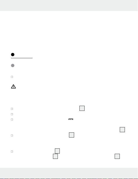
Vi servono
Necessita de
You need
Sie benötigen:
ø 6 mm
A
1
104412-14-01 104412-14-02
7
3
4
2
5
6
9
10
3
Page 4
B
6
8
4
C1
181211
15
Page 5
C2
D
14 13
7
16
17
5
Page 6
E
17
16
F
14
6
Page 7
G
H
12 18
18
19
12
C B A
7
Page 8
4 - 12V, AC/
4 - 12V, DC
I
J
8
Page 9

Introduzione
Scopo d’impiego ............................................................................Pagina 10
Quadro sinottico dei componenti ..................................................Pagina 10
Dotazione .......................................................................................Pagina 11
Dati tecnici ......................................................................................Pagina 12
Sicurezza
Avvisi di sicurezza generali ...........................................................Pagina 12
Indicazioni di sicurezza relative alle batterie ...............................Pagina 13
Montaggio .................................................................................Pagina 14
Avvio
Inserimento / sostituzione delle batterie ........................................Pagina 15
Sincronizzazione trasmettitore / ricevitore ....................................Pagina 16
Impostazione del tipo di segnale ..................................................Pagina 17
Impostazione del volume ...............................................................Pagina 17
Scelta del segnale acustico ...........................................................Pagina 18
Collegare il trasmettitore al sistema per campanello /
campanello esistente ......................................................................Pagina 18
Fissare il trasmettitore all‘impianto
per campanello esistente .............................................Pagina 19
Collegare a un tasto del
campanello esistente ......................................................Pagina 20
Eliminare gli errori ..............................................................Pagina 20
Pulizia e manutenzione .................................................Pagina 20
Smaltimento .............................................................................Pagina 21
Dichiarazione di conformità ......................................Pagina 22
Garanzia .....................................................................................Pagina 23
9 IT/MT
Page 10
Campanello senza fili
Q
Introduzione
Conservate quest’istruzione per bene. Consegnate altresì
tutti i documenti quando date questo prodotto a terzi.
Q
Scopo d’impiego
Questo prodotto è stato realizzato per il trasferimento senza fili del
segnale del campanello. Questo prodotto non è stato realizzato per
l’uso professionale.
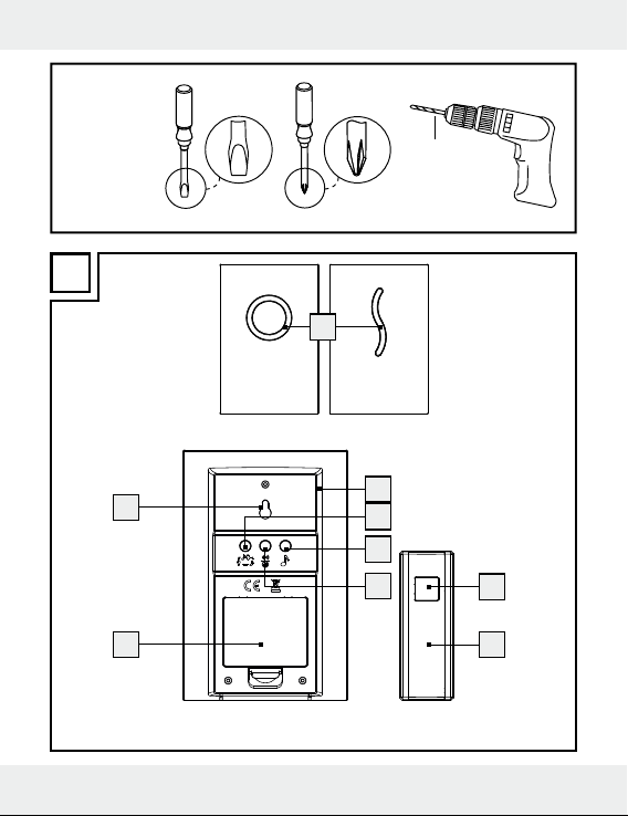
Quadro sinottico dei componenti
Ricevitore
1
Visualizzazione del segnale
2
Altoparlante
3
Tasto per la scelta del tipo di segnale (ottico, acustico, ottico e acustico)
4
Tasto per la scelta della suono
5
Tasto volume/Tasto sincronizzazione
6
Coperchio vano portabatterie
7
Dispositivo di sospensione
8
Vano portabatterie
10 IT/MT
Page 11
Trasmettitore
9
Tasto del campanello
10
Targhetta per il nome
11
Dispositivo di blocco
12
Sostegno (per montaggio a parete)
13
Vano portabatterie
14
Copertura interiore
Montaggio
15
Copertura in gomma
16
Vite
17
Tassello
18
Uscita per il cavo
19
Supporto per il cavo
Dotazione
1 Trasmettitore
1 Ricevitore
3 Batterie da 1,5 V
1 Batteria da 3 V
3 Viti (per il trasmettitore e per il montaggio a parete del ricevitore)
3 Tasselli
5 Targhette nome (per il campanello)
1 Manuale di istruzioni
, tipo AA (ricevitore)
, tipo CR2032 (trasmettitore)
11 IT/MT
Page 12
Dati tecnici
Portata: 150 m (zona aperta)
Frequenza di
trasmissione: 434 MHz
Tipi di batteria: Ricevitore: 3 x 1,5 V
Emettitore: 1 x 3 V
Ricevitore: Volume del segnale acustico (in caso di
regolazione del volume al livello massimo):
ca. 73 dB (a una distanza dall’apparecchio
di 1 m)
Classe di protezione
del trasmettitore: IP44 (resistente agli spruzzi d‘acqua)
(Tipo AA / LR6),
(Tipo CR2032)
Sicurezza
Leggere tutte le indicazioni di sicurezza e le
istruzioni riportate.
CONSERVI TUTTE LE ISTRUZIONI E GLI AVVISI DI SICUREZZA
PER CONSULTARLI IN FUTURO!
Avvisi di sicurezza generali
Quest‘apparecchio può essere utilizzato da bambini di età supe-
riore agli 8 anni, da persone con capacità fisiche, sensoriali o
mentali ridotte o da persone inesperte solo se supervisionate o
12 IT/MT
Page 13
preventivamente istruite sull’utilizzo in sicurezza del prodotto e
solo se informate dei pericoli legati al prodotto stesso. Non
lasciare che i bambini giochino con l‘apparecchio. La pulizia e
la manutenzione non devono essere eseguite dai bambini senza
supervisione.
Controllate che tutti i pezzi siano impeccabili. Il montaggio di
pezzi danneggiati può presentare un pericolo di lesioni.
Indicazioni di sicurezza
relative alle batterie
PERICOLO DI MORTE! Le batterie
potrebbero essere inghiottite, circostanza che può rappresentare
un pericolo di morte. In caso di ingerimento di una batteria chiedere subito l’intervento di un medico.
PERICOLO DI ESPLOSIONE! Non ricaricare mai
batterie non ricaricabili, non cortocircuitarle né aprirle.
Ciò potrebbe causarne il surriscaldamento, l’incendio
o l’esplosione.
Non gettare mai le batterie nel fuoco o in acqua. Le batterie
potrebbero infatti esplodere.
Rimuovere subito dall’apparecchio le batterie esaurite. Sussiste
un notevole pericolo di perdita!
Sostituire sempre tutte le batterie contemporaneamente e inserire
solamente batterie nuove dello stesso tipo.
Non utilizzare tipi diversi di batteria oppure batterie usate e
nuove contemporaneamente.
13 IT/MT
Page 14
Le batterie non devono essere gettate nella spazzatura dome-
stica! Smaltire batterie usate in modo non dannoso per l’ambiente.
Ogni consumatore è obbligato dalla legge di smaltire regolar-
mente le pile!
Tenete le pile lontano dalla portata dei bambini, non gettatele nel
fuoco, non sottoponetelo sotto corto circuito e non smontatele.
In caso di inosservanza delle avvertenze le pile si possono scari-
care tramite la loro tensione finale. Persiste poi il pericolo d’uscita
dell’acido dalle pile. In caso l’acido delle pile sia fuoruscito mentre le pile si trovavano dentro l’apparecchio, toglietele subito per
evitare danni al prodotto!
Evitate il contatto con la pelle, gli occhi e mucosa. In caso di
contatto con l’acido delle pile, lavate subito la parte colpita con
molta acqua e / o consultate un medico!
Non utilizzate pile che si possano ricaricare.
Non sottoponete i poli d’attacco sotto corto circuito.
Non impiegate mai insieme pile vecchie con pile nuove.
Rimuovere le batterie dall’apparecchio qualora questo non
venisse utilizzato per lungo tempo.
Inserendo le batterie fare attenzione a che la polarità sia corretta.
Montaggio
Nota: Per il montaggio del campanello per porta, è necessario
utilizzare un cacciavite e un trapano.
14 IT/MT
Page 15
Nota: Per il montaggio utilizzare solamente le viti e i tasselli in
dotazione.
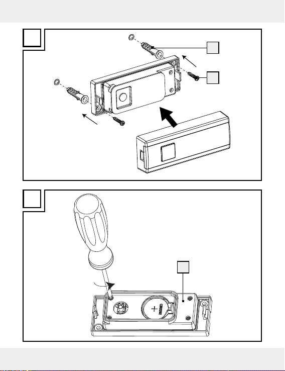
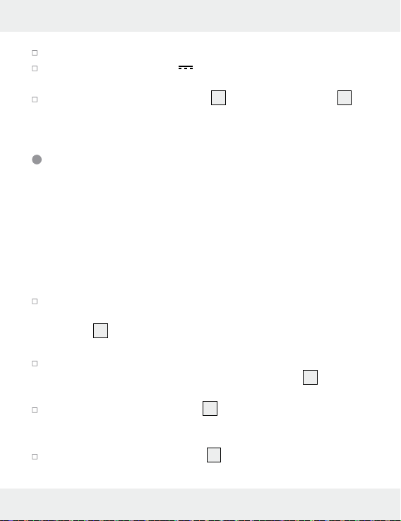
Montaggio del ricevitore (vedi fig. D)
Montaggio dell’emettitore (vedi fig. E)
Avvio
Inserimento/sostituzione delle batterie
Introdurre le batterie per l‘alimentazione prima dell‘utilizzo del
dispositivo.
ATTENZIONE! Utilizzare soltanto il tipo di batterie fornito. In
caso contrario sussiste la possibilità che il prodotto subisca danni.
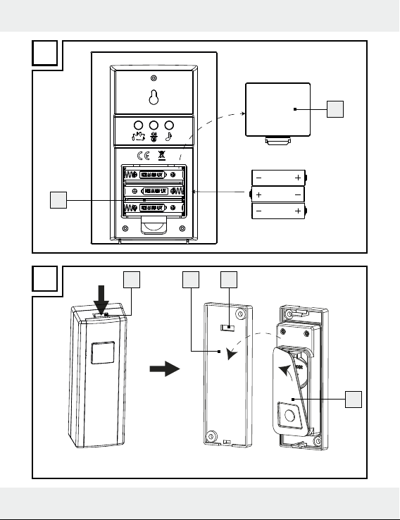
Ricevitore (vedere fig. B):
Rimuovere il coperchio vano batterie 6 sul retro del dispositivo.
Rimuovere eventualmente le batterie scariche.
Inserire le 3 batterie (da 1,5 V , tipo AA).
Nota: Inserendo le batterie, fare attenzione a che sia rispettata
la corretta polarità. Essa viene mostrata nel vano portabatterie
Chiudere il vano portabatterie 8.
Trasmettitore:
Rimuovere il supporto 12 dal retro del trasmettitore premendo sul
dispositivo di blocco
(vedere figura C1).
11
e togliere la copertura in gomma 15
8
.
15 IT/MT
Page 16
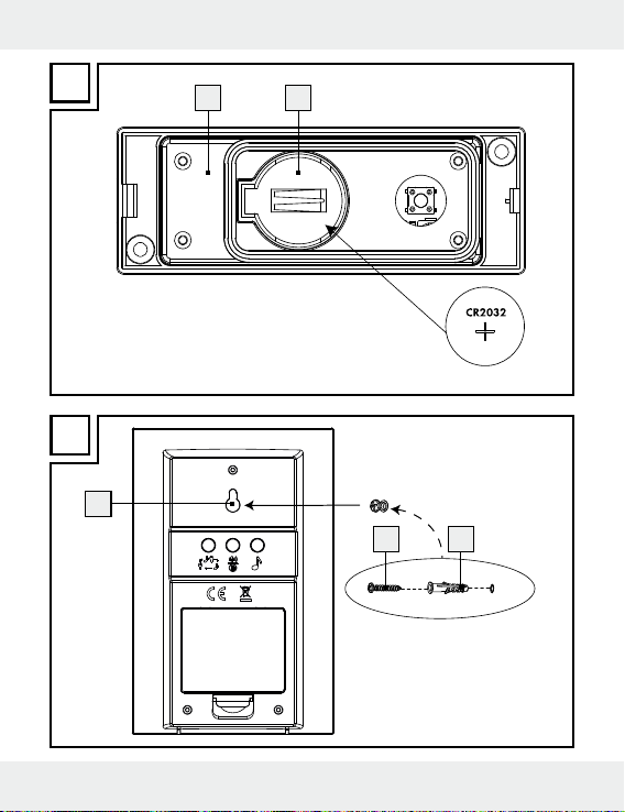
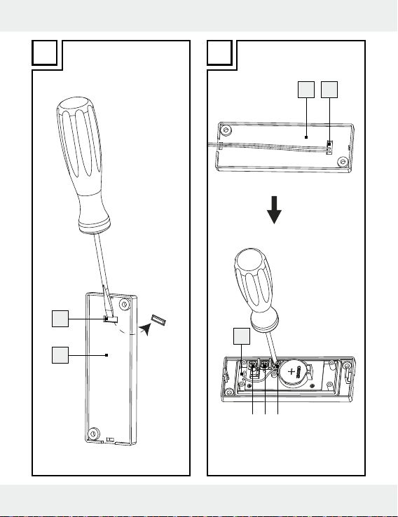
Estrarre eventualmente le batterie scariche (vedere figura C2).
Inserire le batterie (da 3 V , gruppo CR 2032). Il lato segnato
col „+“ deve indicare verso l‘alto.
Montare la copertura di gomma 15, richiudere il sostegno 12
del trasmettitore sul retro del dispositivo.
Sincronizzazione trasmettitore / ricevitore
Il campanello funziona oltre i 434 MHz, una frequenza che si diffonde
ad una distanza abbastanza larga. Per assicurarsi che il funzionamento
del vostro campanello non venga influenzato da quello di un vostro
vicino, bisogna sincronizzare trasmettitore e ricevitore in termini di
codificazione. Ogni trasmettitore ha un suo segnale di codificazione.
Sincronizzare trasmettitore e ricevitore come segue:
Non appena le batterie sono inserite, il ricevitore entra in moda-
lità sincronizzazione per circa un minuto. La visualizzazione del
segnale
lità sincronizzazione.
Potete passare alla modalità sincronizzazione anche manual-
mente, tenendo premuto il tasto di sincronizzazione
3 secondi.
La visualizzazione del segnale 1 sul ricevitore resta accesa per
ca. un minuto indicando così che il ricevitore è in modalità sincro-
nizzazione.
Premere il tasto del campanello 9 del trasmettitore mentre il
ricevitore è in modalità sincronizzazione. Appena il ricevitore
1
sul ricevitore rimane accesa in blu durante la moda-
5
per ca.
16 IT/MT
Page 17

riceve il segnale, la luce blu della visualizzazione del segnale 1
s‘illumina sei volte per segnalare la sincronizzazione avvenuta.
Impostazione del tipo di segnale
Il ricevitore può avere un segnale di ricevimento sia acustico che
ottico o anche acustico e ottico insieme.
Scegliere il segnale attraverso il tasto di scelta tipo segnale 3.
Premere una volta il tasto di scelta tipo segnale 3. Verrà emesso
un segnale acustico e successivamente la visualizzazione del se-
1
gale
si accenderà. Adesso il ricevitore riprodurrà un segnale
acustico e ottico. Premere nuovamente il tasto per la scelta del
tipo di segnale
il ricevitore riprodurrà un segnale acustico. Premere nuovamente
il tasto per la scelta del tipo di segnale
indicherà la segnalazione ottica.
Impostazione del volume
Premere il tasto del volume 5, fino a raggiungere il volume
desiderato. Ci sono 4 possibilità di impostazione del volume totali: molto alto, alto, medio, basso.
3
. Verrà emesso un segnale acustico. Adesso
3
. Adesso il ricevitore
17 IT/MT
Page 18
Scelta del segnale acustico
Nota: Questo campanello per porta dispone di 16 segnali acustici
diversi.
Premere il tasto di selezione della suoneria 4. Il primo segnale
acustico risuona.
Per accedere al segnale acustico successivo, premere nuova-
mente il tasto di selezione dei segnale acustico
Ripetere la procedura fino a quando si è giunti al segnale acu-
stico scelto. L’ultimo segnale acustico scelto viene memorizzato
automaticamente.
4
.
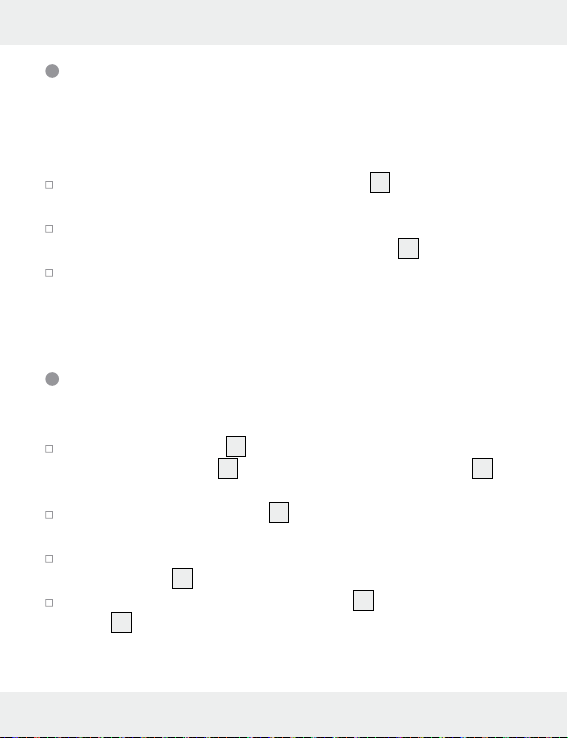
Collegare il trasmettitore al sistema per
campanello / campanello esistente
Rimuovere il supporto 12 dal retro del trasmettitore premendo sul
dispositivo di blocco
(vedere figura C1).
Aprire la copertura interiore 14 con un cacciavite a stella
(vedere figura F).
Aiutandosi con un cacciavite rimuovere la clip di plastica dall‘u-
scita del cavo
Inserire il cavo tra il supporto per il cavo 19 e l‘uscita per il
18
cavo
(vedere figura H).
11
e togliere la copertura in gomma 15
18
(vedere fig. G).
18 IT/MT
Page 19
Con un cacciavite fissare il cavo al collegamento A e C (per il
sistema per campanello) o al collegamento B e C (per il sistema
per il campanello) (vedi fig. H).
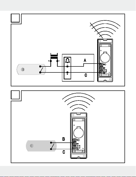
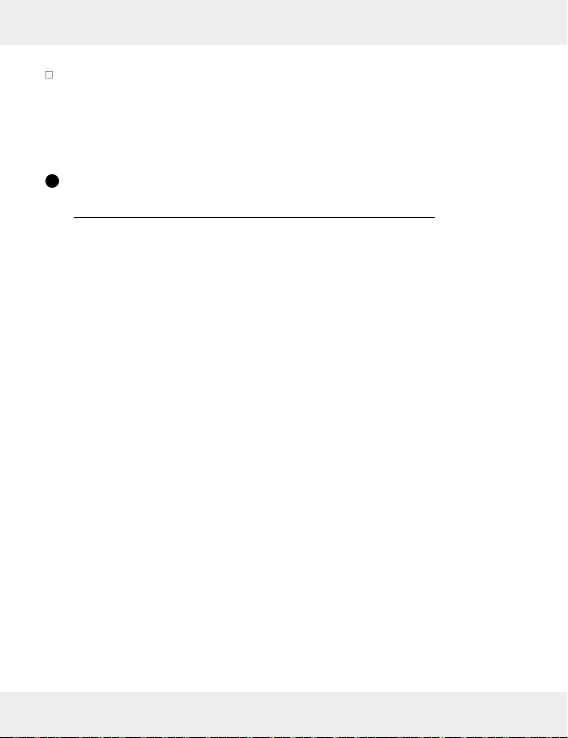
Fissare il trasmettitore all‘impianto per
campanello esistente (vedere fig. l)
Allargare l‘impianto per campanello esistente:
Con questo prodotto è possibile allargare l‘impianto per campanello
esistente.
La tensione di funzionamento del campanello deve essere tra 4–12 V.
Tale criterio vale sia per corrente continua che per una corrente
alternata da 50 Hz. In caso di campanello azionato con corrente
continua, il polo positivo deve essere collegato al contatto C del
trasmettitore e il polo negativo al contatto A del trasmettitore.
IMPORTANTE! Non scambiare mai la polarità. L‘apparecchio
potrebbe subire danni (ulteriori dettagli in fig. I).
I morsetti di collegamento A e C, posti sul retro del trasmettitore come
indicato in fig. I, devono essere collegati direttamente al trasmettitore
del segnare (ad es. campanello). Il tasto del trasmettitore è utilizzabile anche in questa modalità di funzionamento.
Nota: rivolgersi a un elettricista in caso di difficoltà durante
l’installazione.
19 IT/MT
Page 20

Collegare a un tasto del campanello
esistente (vedere fig. J)
Il tasto del campanello non deve essere collegato all‘impianto esistente. La batteria deve restare nel trasmettitore. A tal fine i morsetti B
e C vengono collegati al tasto del campanello con un cavo a due fili.
Il tasto del campanello deve essere collegato esclusivamente con il
trasmettitore.
Eliminare gli errori
Con l’influenza di condizioni ambientali straordinarie (per es. un forte
campo elettromagnetico), il prodotto probabilmente non potrà più
funzionare in modo impeccabile. Togliete in questo caso per ca.
2 minuti le pile di tutti e due gli apparecchi. Procedete infine come
descritto sotto “Sincronizzazione dell’emettitore / ricevitore“.
Scariche elettrostatiche possono portare a disturbi nella funzione.
Togliete in caso di tali disturbi per breve tempo le pile e inseritele
nuovamente. Procedete infine come descritto sotto “Sincronizzazione
dell’emettitore / ricevitore”.
Q
Pulizia e manutenzione
J Non utilizzate per nessuna ragione liquidi o detergenti che
danneggerebbero l‘apparecchio.
20 IT/MT
Page 21
j Pulite esclusivamente l‘esterno dell‘apparecchio con un panno
morbido ed asciutto.
Q
Smaltimento
La confezione è prodotta in materiale riciclabile e biode-
gradabile, smaltibile nei luoghi di raccolta differenziati.
Potete informarvi sulle possibilità di smaltimento del prodotto consumato dall‘amministrazione comunale e cittadina.
Per la salvaguardia della tutela ambientale, quando il
vostro prodotto non funziona più, non gettatelo nei rifiuti
domestici bensì nei luoghi adatti di raccolta. Potete informarvi sui luoghi di raccolta e i loro orari di apertura
dall‘amministrazione competente.
Gli accumulatori difettosi o esausti devono essere riciclati in base alla
direttiva 2006 / 66 / EC. Riconsegnare gli accumulatori e / o i caricabatteria presso gli appositi centri di raccolta.
Vi possono essere conseguenze negative per
l’ambiente a seguito di uno smaltimento non
Pb
corretto delle batterie!
Le batterie non devono essere smaltite nella spazzatura domestica.
Esse possono contenere metalli pesanti velenosi e devono essere
21 IT/MT
Page 22

trattate quali rifiuti speciali. I simboli chimici dei metalli pesanti sono i
seguenti: Cd = cadmio, Hg = mercurio, Pb = piombo. Consegnare
quindi le batterie usate ad un punto di raccolta comunale.
Dichiarazione di conformità
Noi, OWIM GmbH & Co. KG, Stiftsbergstraße 1, D-74167
Neckarsulm, dichiariamo sotto la nostra esclusiva responsabilità che il
prodotto: Campanello senza fili, modelli n° 104412-14-01 /
104412-14-02, Versione: 03 / 2015, alla quale si riferisce questa
dichiarazione, è conforme alle norme / documenti normativi di cui
alla Direttiva 1999 / 5 / EC.
La dichiarazione di conformità completa è reperibile alla pagina web
www.owim.com
22 IT/MT
Page 23

Garanzia
L‘apparecchio è stato prodotto secondo severe direttive di qualità e
controllato con premura prima della consegna. In caso di difetti del
prodotto, l‘acquirente può far valere i propri diritti legali nei confronti
del venditore. Questi diritti legali non vengono limitati in alcun modo
dalla garanzia di seguito riportata.
Se entro tre anni dalla data di acquisto di questo prodotto si rileva un
difetto di materiale o di fabbricazione, il prodotto verrà riparato o sostituito gratuitamente, a nostra discrezione. Il termine di garanzia ha
inizio a partire dalla data di acquisto. Conservare lo scontrino di acquisto originale in buone condizioni. Questo documento servirà a documentare l‘avvenuto acquisto.
L‘apparecchio da Lei acquistato dà diritto ad una garanzia di 3 anni
a partire dalla data di acquisto. La presente garanzia decade nel
caso di danneggiamento del prodotto, di utilizzo o di manutenzione
inadeguati.
La prestazione di garanzia vale sia per difetti di materiale che per difetti di fabbricazione. La presente garanzia non si estende a parti del
prodotto soggette a normale usura e che possono essere identificate,
pertanto, come parti soggette a usura (p. es., le batterie), né a danni
su parti staccabili, come interruttore, batterie o simili, realizzate in vetro.
23 IT/MT
Page 24

Introdução
Utilização adequada .....................................................................Página 25
Vista geral das peças .....................................................................Página 25
Material fornecido ..........................................................................Página 26
Dados técnicos ...............................................................................Página 27
Segurança
Indicações gerais de segurança ...................................................Página 27
Indicações de segurança relativas às pilhas ................................Página 28
Montagem .................................................................................Página 30
Colocação em funcionamento
Colocar / substituir as pilhas ..........................................................Página 30
Sincronizar o emissor / recetor ......................................................Página 31
Configurar o tipo de sinal ..............................................................Página 32
Regular o volume ............................................................................Página 33
Selecionar o sinal sonoro ..............................................................Página 33
Ligar o emissor ao sistema de campainha já existente /
à campainha existente ...................................................................Página 33
Ligar o emissor a um sistema
de campainha existente................................................Página 34
Ligar a um botão de campainha existente ....Página 35
Eliminar o erro .......................................................................Página 35
Limpeza e conservação .................................................Página 36
Eliminação ..................................................................................Página 36
Declaração de conformidade ...................................Página 37
Garantia ......................................................................................Página 38
24 PT
Page 25

Campainha de porta de design sem fios
Introdução
Conserve cuidadosamente este manual de instruções.
Se entregar o produto a terceiros, entregue também os
respetivos documentos.
Utilização adequada
Este produto destina-se à transmissão sem fio do sinal da campainha.
Este produto não é indicado para uma utilização comercial.
Vista geral das peças
Recetor
1
Indicador de sinal
2
Coluna
3
Botão de seleção do tipo de sinal (sinal ótico, acústico, sinal
ótico e acústico)
4
Botão de seleção do toque da campainha
5
Botão do volume/botão de sincronização
6
Tampa do compartimento das pilhas
7
Dispositivo de suspensão
8
Compartimento das pilhas
25 PT
Page 26

Emissor
9
Botão da campainha
10
Placa de identificação
11
Bloqueio
12
Suporte (para montagem na parede)
13
Compartimento das pilhas
14
Cobertura interior
Montagem
15
Cobertura de borracha
16
Parafuso
17
Bucha
18
Saída do cabo
19
Suporte do cabo
Material fornecido
1 emissor
1 recetor
3 pilhas 1,5 V
1 pilha 3 V
3 parafusos (para emissor e para a montagem na parede do recetor)
3 buchas
5 placas de identificação (para a campainha)
1 manual de instruções
, tipo AA (recetor)
, tipo CR2032 (emissor)
26 PT
Page 27

Dados técnicos
Alcance: 150 m (espaço aberto)
Frequência de emissão: 434 MHz
Tipos de pilhas: Recetor: 3 x 1,5 V
emissor: 1 x 3 V
Recetor: Volume do sinal sonoro (no caso de
configuração máx. do volume): cerca
de 73 dB
(com 1m de distância do aparelho)
Tipo de proteção do recetor: IP44 (proteção contra salpicos de
água)
(tipo AA / LR6),
(tipo CR2032)
Segurança
Leia todas as indicações de segurança e instruções.
GUARDE TODAS AS INDICAÇÕES DE SEGURANÇA E
INSTRUÇÕES PARA FUTURAS UTILIZAÇÕES!
Indicações gerais de segurança
Este aparelho pode ser utilizado por crianças a partir dos 8 anos,
assim como por pessoas com capacidades físicas, sensoriais ou
mentais reduzidas ou deficiências na experiência e conhecimento,
se forem vigiadas ou instruídas em relação ao uso seguro do
27 PT
Page 28

aparelho e se compreenderem os perigos que daí possam resultar. As crianças não devem brincar com o aparelho. A limpeza e
a manutenção pelo utilizador não devem ser realizadas por
crianças sem vigilância.
Verifique todas as peças quanto ao seu estado. Existe perigo de
ferimento em caso de montagem de peças danificadas.
Indicações de segurança
relativas às pilhas
PERIGO DE MORTE! As pilhas podem ser engolidas,
constituindo perigo de morte. Contacte imediatamente um
médico no caso de ingestão de uma pilha.
PERIGO DE EXPLOSÃO! Nunca recarregue pilhas
não recarregáveis, não provoque curto-circuito nem as
abra. As consequências poderão ser o sobreaqueci-
mento, perigo de incêndio ou a explosão.
Nunca atire pilhas para o fogo ou água. As pilhas podem
explodir.
Retire de imediato as pilhas gastas do aparelho. Existe um
elevado risco de derrame!
Substitua sempre todas as pilhas em simultâneo e coloque
apenas pilhas do mesmo tipo.
Não utilize tipos diferentes, nem misture pilhas novas e usadas.
As pilhas não devem ser depositadas no lixo doméstico. Elimine
as pilhas usadas de forma ecológica.
28 PT
Page 29

Cada consumidor é legalmente obrigado a eliminar corretamente
as pilhas!
Mantenha as pilhas longe do alcance das crianças, não as atire
para o fogo, proteja-as contra curto-circuitos e não as desmonte.
Em caso de inobservância das indicações, as pilhas podem ficar
descarregadas para além da sua tensão final. Neste caso, subsiste o perigo de derrame. Se as pilhas começarem a derramar
ácido dentro do aparelho, retire-as imediatamente para evitar
danos no mesmo!
Evite o contacto com a pele, os olhos e mucosas. No caso de
contacto com o ácido da pilha, lave a zona afetada com
bastante água e / ou consulte um médico!
Não utilize pilhas recarregáveis.
De modo algum remedeie os pólos de ligação.
Nunca utilize pilhas usadas e novas em simultâneo.
Retire as pilhas do aparelho caso não tenham sido utilizadas há
muito tempo.
Ao colocar as pilhas, tenha em atenção a polaridade correta!
29 PT
Page 30

Montagem
Nota: Para a montagem da campainha necessita de uma chave de
parafuso e um berbequim.
Nota: Utilize para a montagem apenas os parafusos e buchas
fornecidos.
Aplicar o recetor (ver fig. D)
Aplicar o emissor (ver fig. E)
Colocação em funcionamento
Colocar/substituir as pilhas
Antes da colocação em funcionamento do aparelho, insira as
pilhas para a alimentação de energia.
CUIDADO! Utilize apenas o tipo de pilha indicado. Caso
contrário, o produto poderá sofrer danos.
Recetor (ver fig. B):
Remova a tampa do compartimento das pilhas 6 na parte
traseira do aparelho.
Retire as pilhas usadas, se necessário.
Insira as 3 pilhas (1,5 V , tipo AA).
Nota: Tenha em atenção a polaridade correta. Esta é indicada
no compartimento das pilhas
Feche o compartimento das pilhas 8.
8
.
30 PT
Page 31

Emissor:
Remova o suporte 12 na parte traseira do emissor ao pressionar
na trava
11
e retire a cobertura em borracha 15 (ver fig. C1).
Retire as pilhas usadas, se necessário (ver fig. C2).
Insira uma pilha (3 V , tipo CR 2032). O lado assinalado com
„+“ terá que apontar para cima.
Coloque a cobertura em borracha 15 e volte a fechar o
12
suporte
do emissor na parte traseira do aparelho.
Sincronizar o emissor / recetor
A campainha funciona através de 434 MHz o que é uma frequência
muito ampla. Para assegurar que as funções da sua campainha não
sejam influenciadas por outras campainhas da sua vizinhança, o
emissor e o recetor devem ser sincronizados em relação à cifragem
do sinal. Cada emissor tem a sua própria cifragem de sinal.
Sincronize o emissor e recetor como se segue:
Assim que as pilhas estão colocadas, o recetor entra durante
cerca de 1 minuto no modo de sincronização. O indicador de
1
sinal
no recetor acende-se durante o modo de sincronização
constantemente em azul.
Também pode entrar manualmente no modo de sincronização
ao manter durante cerca de 3 segundos o botão de sincroniza-
5
ção
.
31 PT
Page 32

O indicador de sinal 1 do recetor acende-se constantemente
durante cerca de 1 minuto e mostra assim que o recetor se
encontra em modo de sincronização.
Prima o botão da campainha 9 do emissor durante que o rece-
tor se encontra no modo de sincronização. Assim que o recetor
recebeu o sinal, a luz azul do indicador de sinal
1
começa a
piscar 6 vezes para assinalar que a sincronização foi bem sucedida.
Configurar o tipo de sinal
O recetor pode apresentar um sinal de porta recebido ótico ou
acústico ou ótico e acústico.
Selecione com o botão de seleção do tipo de sinal 3 se o sinal
deve ser apresentado ótico ou acústico ou ótico e acústico.
Prima 1 vez no botão de seleção do tipo de sinal 3. Soa um
sina acústico e o indicador de sinal
recetor transmite agora o sinal sonoro acústico e ótico. Prima novamente o botão de seleção do tipo de sinal
acústico. O recetor transmite agora o sinal sonoro acústico.
Prima novamente o botão de seleção do tipo de sinal
O recetor visualiza agora o sinal sonoro ótico.
1
acende-se depois. O
3
. Soa um sinal
3
.
32 PT
Page 33

Regular o volume
Prima o botão do volume 5 até atingir o volume desejado. Existe no
total 4 configurações possíveis de volume: muito alto, alto, médio,
baixo, muito baixo.
Selecionar o sinal sonoro
Nota: A campainha dispõe de 16 diferentes sinais sonoros.
Prima o botão de seleção do toque da campainha 4. Toca o
primeiro sinal sonoro.
Prima novamente o botão de seleção do toque da campainha 4
para conseguir o sinal sonoro seguinte.
Repita este procedimento até que tenha selecionado o sinal
sonoro pretendido. O sinal sonoro selecionado por último é
memorizado automaticamente.
Ligar o emissor ao sistema de campainha
já existente / à campainha existente
Remova o suporte 12 na parte traseira do emissor ao pressionar
na trava
Abra a cobertura interior 14 com uma chave Philipps (ver fig. F).
Remova com a chave de fendas o clipe plástico na saída do
cabo
11
e retire a cobertura em borracha 15 (ver fig. C1).
18
(ver fig. G).
33 PT
Page 34

Passe o cabo pelo suporte do cabo 19 e pela saída do cabo 18
(ver fig. H).
Ligue o cabo com uma chave de fendas às ligações A e C
(para um sistema de campainha já existente) ou às ligações
B e C (para uma campainha já existente) (ver fig. H).
Ligar o emissor a um sistema de
campainha existente (ver fig. I)
Expandir o sistema de campainha existente:
Um sistema de campainha já existente pode ser expandido por este
produto.
A tensão de serviço do sistema de campainha pode encontrar-se
entre 4 e 12 V. Neste caso não importa se se trata de uma tensão
contínua ou de uma tensão alternada de 50 Hz. Se o sistema de
campainha já existente é um sistema acionado por tensão contínua,
o polo positivo da campainha tem de ser ligado ao contacto C do
emissor e o polo negativo ao contacto A do emissor.
IMPORTANTE! Troque jamais a polaridade. O aparelho pode ser
danificado (para mais pormenores observe a fig. I).
Os terminais de ligação A e C, que, como indicado na fig. I, se
encontram em cima da placa do emissor têm de ser ligados diretamente com as ligações elétricas do emissor do sinal (p. ex. campainha). Neste modo de funcionamento também deve utilizar o
interruptor do emissor.
34 PT
Page 35

Nota: Caso tenha dificuldades na instalação, consulte um técnico
eletricista especializado.
Ligar a um botão de campainha
existente (ver fig. J)
O botão da campainha não pode estar ligado com o sistema de
campainha existente. As pilhas devem permanecer no emissor. Para
isso, os terminais de ligação B e C são ligados com uma linha de
dois fios ao botão da campainha. O botão da campainha pode
estar ligado exclusivamente com o emissor.
Eliminar o erro
Depois da influência de condições ambientais extraordinárias (p. ex.,
um forte campo eletromagnético), o produto já não pode funcionar
perfeitamente. Neste caso, retire dos dois aparelhos as pilhas
durante cerca de 2 mintuos. Proceda depois como descrito em
„Sincronizar o emissor/recetor“.
Cargas eletrostáticas podem causar interferências no funcionamento.
No caso de interferências deste tipo no funcionamento, retire as
pilhas durante um curto espaço de tempo e volte a colocá-las.
Proceda depois como descrito em „Sincronizar o emissor/recetor“.
35 PT
Page 36

Limpeza e conservação
Nunca utilize líquidos e detergentes, pois estes danificam o
aparelho.
Limpe o aparelho apenas por fora com um pano seco e macio.
Eliminação
A embalagem é composta por materiais recicláveis, que
pode eliminar através dos pontos de reciclagem locais.
As possibilidades de reciclagem dos artigos utilizados poderão ser
averiguadas no seu Município ou Câmara Municipal.
Para proteção do ambiente, não elimine este produto
juntamente com o lixo doméstico; entregue-o num ponto
de recolha adequado. Pode informar-se no seu município
sobre os locais de recolha adequados e o seu período de
funcionamento.
As pilhas avariadas ou gastas têm de ser recicladas de acordo com
a diretiva 2006 / 66 /CE. Entregue as pilhas e / ou o aparelho nos
locais específicos destinados à sua recolha.
Danos ambientais devido à
eliminação incorreta das pilhas!
Pb
36 PT
Page 37

As pilhas não podem ser eliminadas no lixo doméstico. Podem conter
metais pesados nocivos e estão sujeitas à regulação de lixos tóxicos.
Os símbolos químicos dos metais pesados são os seguintes:
Cd = cádmio, Hg = mercúrio, Pb = chumbo. Como tal, deposite as
pilhas utilizadas num ponto de recolha adequado do seu município.
Declaração de conformidade
Nós, a OWIM GmbH & Co. KG, Stiftsbergstraße 1, D-74167
Neckarsulm, declaramos com o presente que o produto: Campainha
de porta de design sem fios, n° do modelo: 104412-14-01 /
104412-14-02, versão: 03 / 2015, no que se refere esta declaração,
corresponde às normas/aos documentos normativos da diretiva
1999 / 5 /CE.
Se necessário, pode efetuar o download desta documentação em
www.owim.com.
37 PT
Page 38

Garantia
O aparelho foi cuidadosamente fabricado segundo rigorosas directivas de qualidade e meticulosamente testado antes da sua distribuição.
Em caso de falhas deste aparelho, possui direitos legais relativamente
ao vendedor do aparelho. Os seus direitos legais não estão limitados
pela garantia representada de seguida.
Tem sobre este aparelho 3 anos de garantia a partir
pra. A validade da garantia iniciao talão da caixa como comprovativo da compra. Esse documento é
necessário para comprovar a compra.
Caso num espaço de tempo de 3 anos a partir da data da compra
deste aparelho surja um erro de material ou de fabrico, o aparelho
será reparado ou substituído por nós – segundo a nossa escolha – e
sem qualquer custo. Esta garantia expira se o aparelho estiver danificado, se não for devidamente utilizado ou se não for efectuada a devida manutenção.
A garantia é válida em caso de defeitos de material ou de fabrico.
Esta garantia não é extensível a componentes do produto que se desgastam com o uso e que, por isso, podem ser consideradas peças de
desgaste (por ex.º pilhas) ou a danos em peças frágeis, por ex.º interruptores, baterias ou peças de vidro.
38 PT
se com a data de compra. Guarde
da data de com-
Page 39

Introduction
Intended use .......................................................................................Page 40
Parts and features ...............................................................................Page 40
Included items .....................................................................................Page 41
Technical data ....................................................................................Page 42
Safety
General safety information ................................................................Page 42
Safety instructions for batteries ..........................................................Page 43
Assembly ........................................................................................Page 44
Preparing for use
Inserting / replacing the batteries ......................................................Page 45
Synchronising transmitter / receiver ...................................................Page 46
Setting the signal type ........................................................................Page 47
Setting the volume ..............................................................................Page 47
Selecting the chime .............................................................................Page 48
The procedure for connecting the transmitter to
existing bell system or existing doorbell button ................................Page 48
Connecting the transmitter to a
existing bell system...............................................................Page 49
Connecting a existing doorbell button ................Page 49
Troubleshooting........................................................................Page 50
Cleaning and maintenance .............................................Page 50
Disposal ............................................................................................Page 51
Declaration of conformity................................................Page 52
Warranty ........................................................................................Page 52
39 GB/MT
Page 40

Premium Wireless Doorbell
Introduction
Keep these instructions in a safe place. If you pass the
product on to anyone else, please ensure that you also pass
on all the documentation.
Intended use
This product is intended for the wireless transmission of the doorbell
signal. The product is not intended for commercial use.
Parts and features
Receiver
1
Signal indicator
2
Speaker
3
Signal type selector button
(optical, acoustic, optical and acoustic signal)
4
Melody selection button
5
Volume / Synchronisation button
6
Battery compartment cover
7
Hanger
8
Battery compartment
40 GB/MT
Page 41

Transmitter
9
Chime button
10
Name plate
11
Lock
12
Holder (for wall mounting)
13
Battery compartment
14
Inner cover
Mounting
15
Rubber cover
16
Screw
17
Dowel
18
Cable exit hole
19
Cable holder
Included items
1 Transmitter
1 Receiver
3 Batteries 1.5 V
1 Battery 3 V
3 Screws (for transmitter and for mounting the receiver on a wall)
3 Dowels
5 Name plates (for the doorbell)
1 Operating instructions
, type AA (receiver)
, type CR2032 (transmitter)
41 GB/MT
Page 42

Technical data
Range: 150 m (unobstructed area)
Transmission frequency: 434 MHz
Battery types: Receiver: 3 x 1.5 V
Transmitter: 1 x 3 V
Receiver: Audible signal volume (at maximum
volume setting): approx. 73 dB (at a
distance of 1 m from the device)
Ingress protection rating
of the transmitter: IP44 (splash water proof)
(type AA / LR6),
(type CR2032)
Safety
Read all safety information and instructions!
STORE ALL SAFETY INFORMATION AND INSTRUCTIONS IN A
SAFE PLACE IN CASE YOU NEED TO REFER TO THEM AGAIN
IN THE FUTURE!
General safety information
This appliance can be used by children aged from 8 years and
above and persons with reduced physical, sensory or mental capabilities or lack of experience and knowledge if they have been
given supervision or instruction concerning use of the
42 GB/MT
Page 43

appliance in a safe way and understand the hazards involved.
Children shall not play with the appliance. Cleaning and user
maintenance shall not be made by children without supervision.
Check that all parts are in sound condition. If you use damaged
parts when assembling the device, you risk injury.
Safety instructions for batteries
DANGER TO LIFE! Batteries can be swallowed,
which can prove fatal. Consult a doctor immediately if anyone
swallows a battery.
EXPLOSION HAZARD! Never recharge non-
rechargeable batteries, short-circuit and / or open bat-
teries. This can cause them to overheat, burn or burst.
Never throw batteries into fire or water. The batteries may explode.
Immediately remove depleted batteries from the device; other-
wise there will be an increased risk of leakage!
Always replace all the batteries at the same time and insert
batteries of the same type.
Do not use different types of batteries or mix used and new
batteries together.
Batteries do not belong in household refuse. Dispose of used
batteries in an environmentally friendly manner.
Consumers are under a legal obligation to dispose of batteries in
the proper way.
Keep the battery out of the reach of children, do not dispose of
the battery in fire, do not short-circuit it, and do not take it apart.
43 GB/MT
Page 44

Failure to observe these instructions may result in the battery dis-
charging beyond its end voltage, which poses a risk of leakage.
If the battery in your instrument has leaked, have it removed immediately to prevent damage to the instrument.
Avoid contact with skin, eyes and mucous membrane. In the event
of contact with battery acid, rinse the affected area with plenty of
water and / or consult a doctor.
Never use rechargeable batteries.
The supply terminals are not to be short-circuited.
Do not mix old batteries with new ones.
Remove the batteries from the device if they have not been used
for a long period.
Make sure you insert the batteries the right way round (polarity).
Assembly
Note: You will need a screwdriver and a drill to assemble the
doorbell.
Note: Only use the screws and dowels supplied for the assembly of
the device.
Mount the receiver (see Fig. D)
Mount the transmitter (see Fig. E)
44 GB/MT
Page 45

Preparing for use
Inserting / replacing the batt eries
Insert the batteries to provide power to the device before prepar-
ing it for use.
CAUTION! Use the indicated battery types only. Failure to ob-
serve this advice may result in damage to the product.
Receiver (see Fig. B):
Remove the battery compartment cover 6 from the back of the
device.
Remove the used batteries, if present.
Insert 3 batteries (1.5 V , type AA).
Note: Ensure correct polarity. This is indicated in the battery
compartment
Close the battery compartment 8.
Transmitter:
Remove the holder 12 by pressing the lock 11 from the back of
the transmitter and remove the rubber cover
Remove the used batteries, if present (see fig. C2).
Insert a battery (3 V , type CR 2032). The side marked “+”
must face upwards.
Install the rubber cover 15, close the holder 12 of the transmitter
back on to the back of the device.
8
.
15
(see fig. C1).
45 GB/MT
Page 46

Synchronising transmitter / receiver
The doorbell works on 434 MHz which is a quite common frequency. To ensure that the function gets no influenced be doorbells in
the neighborhood, the transmitter and the receiver hence have to be
synchronized in regard of the encryption. Every transmitter is working
with a different encryption of the signal.
Synchronise the transmitter and receiver as follows:
As soon as the batteries are installed, the receiver enters synchro-
nizing mode for approx. 1 minute. During the synchronizing
mode, the signal indicator
You can also manually enter synchronising mode by holding the
synchronising button
The signal indicator 1 on the receiver will steadily light up for
approx. 1 minute, to indicate that the receiver is in synchronizing
mode.
Press the chime button 9 of the transmitter, while the receiver is
in synchronise mode. If the receiver receives the signal, the steady
blue light of the signal indicator
that the synchronization is successful.
1
steadily lights up in blue color.
5
for approx. 3 seconds.
1
flickers 6 times to indicate
46 GB/MT
Page 47

Setting the signal type
The receiver can indicate the reception of a door signal either both
optically and acoustically, acoustically or optically.
Using the signal type selector button 3, select whether the
signal is to be indicated both optically and acoustically or acous-
tically or optically.
Press the signal type selector button 3 once. An acoustical
signal will sound up and the afterwards the signal indicator
1
will flash. The receiver will now indicate the door signal acousti-
cally and optically. Press again the signal type selector button
An acoustical signal will sound. The receiver will now indicate the
door signal acoustically. Press again the signal type selector
3
button
. The receiver will now indicate the door signal in an
optical way.
Setting the volume
Press the volume button 5 until the desired volume is reached.
There are a total of 4 possible volume settings: very loud, loud,
medium, soft.
3
.
47 GB/MT
Page 48

Selecting the chime
Note: The doorbell has 16 different chimes.
Press the melody selection button 4. The first audible signal
sounds.
Press the melody selection button 4 again to move on to the
next audible signal.
Repeat this process until you have selected your desired audible
signal. The last-selected audible signal is automatically stored.
The procedure for connecting the
transmitter to existing bell system or
existing doorbell button
Remove the holder 12 by pressing the lock 11 from the back of
the transmitter and remove the rubber cover
Open the inner cover 14 by cross head screw driver (see fig. F).
Remove the plastic clip of cable exit hole 18 with a flat head
screw driver (see fig. G).
Insert the cable through cable holder 19 and cable exit hole 18
(see fig. H).
Connect cable to the terminals A and C (for connecting to exist-
ing doorbell) or the terminals B and C (for connecting to existing
door bell button) by using screw driver (see fig. H).
15
(see fig. C1).
48 GB/MT
Page 49

Connecting the transmitter
to a existing bell system (see Fig. I)
Extension of an already existing doorbell system:
An already existing doorbell system can be extended with this wireless doorbell.
The operating voltage of the doorbell system must be between 4–12 V.
It makes no difference whether this comes from direct current or 50 Hz
alternating current. In the event that you are dealing with an existing
doorbell system using direct current, you must connect the positive terminal of the doorbell to contact C of the transmitter and the negative
terminal to contact A of the transmitter.
IMPORTANT! Never reverse polarity. This can damage the device.
The connection terminals A and C, found on the circuit board of the
transmitter as shown in fig. I must be connected directly to the electrical connection terminals of the signal generators (e.g. bell). The
button of the transmitter may also be used for this type of operation.
Note: Contact a qualified electrician in case of problems during
installation.
Connecting a existing
doorbell button (see Fig. J)
The separate bell button must not be connected to the existing doorbell system. The battery must remain in the transmitter. The B and C
49 GB/MT
Page 50

terminals are to this purpose with a two-core cable connected to the
bell push. The bell push may only be connected to the transmitter.
Troubleshooting
After the influence of extraordinary environmental conditions (e.g. a
strong electromagnetical field) the function of the item may be affected. In this case, please take off the batteries of both appliances
for approximately 2 minutes. Then proceed again as described in the
section “Synchronising the transmitter / receiver”.
Electrostatic discharges may lead to malfunctions. If such malfunctions
do occur, remove the battery for a short time and then replace it again.
Then proceed again as described in the section “Synchronising the
transmitter / receiver”.
Cleaning and maintenance
Under no circumstances should you use liquids or detergents, as
these will damage the device.
The device should only be cleaned on the outside with a soft dry
cloth.
50 GB/MT
Page 51

Disposal
The packaging is made entirely of recyclable materials,
which you may dispose of at local recycling facilities.
Contact your local refuse disposal authority for more details of how
to dispose of your worn-out product.
To help protect the environment, please dispose of the
product properly when it has reached the end of its useful
life and not in the household waste. Information on collection points and their opening hours can be obtained from
your local authority.
Faulty or used batteries must be recycled in accordance with Directive
2006 / 66 / EC. Please return the batteries and / or the device to the
available collection points.
Environmental damage through
incorrect disposal of the batteries!
Pb
Batteries may not be disposed of with the usual domestic waste. They
may contain toxic heavy metals and are subject to hazardous waste
treatment rules and regulations. The chemical symbols for heavy metals are as follows: Cd = cadmium, Hg = mercury, Pb = lead. That is
why you should dispose of used batteries at a local collection point.
51 GB/MT
Page 52

Declaration of conformity
We, OWIM GmbH & Co. KG, Stiftsbergstraße 1, D-74167 Neckarsulm, hereby declare under our sole responsibility that the product:
Premium Wireless Doorbell, Model No.: 104412-14-01 / 104412-14Version: 03 / 2015, to which this declaration refers, complies with the
standards / normative documents of 1999 / 5 / EC.
The complete declaration of conformity can be viewed at:
www.owim.com.
02,
Warranty
The device has been manufactured to strict quality guidelines and
meticulously examined before delivery. In the event of product defects
you have legal rights against the retailer of this product. Your legal
rights are not limited in any way by our warranty detailed below.
The warranty for this device is 3 years from the date of purchase.
Should this device show any fault in materials or manufacture within
52 GB/MT
Page 53

three years from the date of purchase, we will repair or replace it - at
our choice - free of charge to you.
The warranty period begins on the date of purchase. Please keep the
original sales receipt in a safe location. This document is required as
your proof of purchase. This warranty becomes void if the device has
been damaged or improperly used or maintained.
The warranty applies to faults in material or manufacture. This warranty does not cover product parts subject to normal wear, thus possibly considered consumables (e.g. batteries) or for damage to fragile
parts, e.g. switches, rechargeable batteries or glass parts.
53 GB/MT
Page 54

Einleitung
Bestimmungsgemäße Verwendung ...................................................Seite 55
Teileübersicht ......................................................................................Seite 55
Lieferumfang .......................................................................................Seite 56
Technische Daten................................................................................Seite 57
Sicherheit
Allgemeine Sicherheitshinweise .........................................................Seite 57
Sicherheitshinweise zu Batterien ........................................................Seite 58
Montage ..........................................................................................Seite 59
Inbetriebnahme
Batterien einsetzen / wechseln ...........................................................Seite 60
Sender / Empfänger synchronisieren .................................................Seite 61
Signalart einstellen .............................................................................Seite 62
Lautstärke einstellen ............................................................................Seite 62
Signalton auswählen ..........................................................................Seite 63
Sender an bestehendes Türklingelsystem /
bestehende Türklingel anschließen....................................................Seite 63
Sender an eine vorhandene
Klingelanlage anschließen..............................................Seite 64
An eine vorhandene
Klingeltaste anschließen ...................................................Seite 65
Fehler beseitigen .....................................................................Seite 65
Reinigung und Pflege ..........................................................Seite 66
Entsorgung ....................................................................................Seite 66
Konformitätserklärung ......................................................Seite 67
Garantie ..........................................................................................Seite 68
54 DE/AT/CH
Page 55

Design-Funktürklingel
Einleitung
Bewahren Sie diese Anleitung gut auf. Händigen Sie alle
Unterlagen bei Weitergabe des Produkts an Dritte ebenfalls mit aus.
Bestimmungsgemäße Verwendung
Dieses Produkt ist zur drahtlosen Übertragung des Türklingelsignals
bestimmt. Dieses Produkt ist nicht für den gewerblichen Einsatz
bestimmt.
Teileübersicht
Empfänger
1
Signalanzeige
2
Lautsprecher
3
Signalart-Auswahltaste (optisches, akustisches, optisches und
akustisches Signal)
4
Klingelton-Auswahltaste
5
Lautstärketaste / Synchronisationstaste
6
Batteriefachdeckel
7
Aufhängevorrichtung
8
Batteriefach
55 DE/AT/CH
Page 56

Sender
9
Klingeltaste
10
Namensschild
11
Sperre
12
Halterung (für Wandmontage)
13
Batteriefach
14
Innenabdeckung
Montage
15
Gummiabdeckung
16
Schraube
17
Dübel
18
Kabelausgang
19
Kabelhalterung
Lieferumfang
1 Sender
1 Empfänger
3 Batterien 1,5 V
1 Batterie 3 V
3 Schrauben (für Sender und für Wandmontage des Empfängers)
3 Dübel
5 Namensschilder (für die Türklingel)
1 Bedienungsanleitung
, Typ AA (Empfänger)
, Typ CR2032 (Sender)
56 DE/AT/CH
Page 57

Technische Daten
Reichweite: 150 m (offener Bereich)
Sendefrequenz: 434 MHz
Batterietypen: Empfänger: 3 x 1,5 V
Sender: 1 x 3 V
Empfänger: Signaltonlautstärke (bei max.
Lautstärkeeinstellung): ca. 73 dB
(bei Geräteabstand von 1 m)
Schutzart Sender: IP44 (spritzwassergeschützt)
(Typ AA / LR6),
(Typ CR2032)
Sicherheit
Lesen Sie alle Sicherheitshinweise und Anweisungen.
BEWAHREN SIE ALLE SICHERHEITSHINWEISE UND ANWEISUNGEN FÜR DIE ZUKUNFT AUF!
Allgemeine Sicherheitshinweise
Dieses Gerät kann von Kindern ab 8 Jahren und darüber sowie
von Personen mit verringerten physischen, sensorischen oder men-
talen Fähigkeiten oder Mangel an Erfahrung und Wissen benutzt
werden, wenn sie beaufsichtigt oder bezüglich des sicheren Ge-
brauchs des Gerätes unterwiesen wurden und die daraus resultie-
renden Gefahren verstehen. Kinder dürfen nicht mit dem Gerät
57 DE/AT/CH
Page 58

spielen. Reinigung und Benutzerwartung dürfen nicht von Kindern
ohne Beaufsichtigung durchgeführt werden.
Kontrollieren Sie alle Teile auf ihre Unversehrtheit. Bei der Mon-
tage beschädigter Teile besteht Verletzungsgefahr.
Sicherheitshinweise zu Batterien
LEBENSGEFAHR! Batterien können verschluckt
werden, was lebensgefährlich sein kann. Nehmen Sie sofort ärzt-
liche Hilfe in Anspruch, wenn eine Batterie verschluckt wurde.
EXPLOSIONSGEFAHR! Laden Sie nicht aufladbare
Batterien niemals wieder auf, schließen Sie sie nicht
kurz und / oder öffnen Sie sie nicht. Überhitzung,
Brandgefahr oder Platzen können die Folge sein.
Werfen Sie Batterien niemals in Feuer oder Wasser. Die Batterien
können explodieren.
Entfernen Sie erschöpfte Batterien umgehend aus dem Gerät. Es
besteht erhöhte Auslaufgefahr!
Tauschen Sie immer alle Batterien gleichzeitig aus und setzen Sie
nur Batterien des gleichen Typs ein.
Verwenden Sie keine unterschiedlichen Typen oder gebrauchte
und neue Batterien miteinander.
Batterien gehören nicht in den Hausmüll. Entsorgen Sie
verbrauchte Batterien umweltgerecht.
Jeder Verbraucher ist gesetzlich verpflichtet, Batterien ordnungs-
gemäß zu entsorgen!
58 DE/AT/CH
Page 59

Halten Sie Batterien von Kindern fern, werfen Sie Batterien nicht
ins Feuer, schließen Sie Batterien nicht kurz und nehmen Sie sie
nicht auseinander.
Bei Nichtbeachtung der Hinweise können die Batterien über ihre
Endspannung hinaus entladen werden. Es besteht dann die Ge-
fahr des Auslaufens. Falls die Batterien in Ihrem Gerät ausgelau-
fen sein sollten, entnehmen Sie diese sofort, um Schäden am
Gerät vorzubeugen!
Vermeiden Sie den Kontakt mit Haut, Augen und Schleimhäuten.
Bei Kontakt mit Batteriesäure spülen Sie die betroffene Stelle mit
reichlich Wasser ab und / oder suchen Sie einen Arzt auf!
Verwenden Sie keine aufladbaren Batterien.
Schließen Sie die Anschlusspole keinesfalls kurz.
Verwenden Sie niemals gebrauchte und neue Batterien zusammen.
Entfernen Sie die Batterien, wenn sie längere Zeit nicht verwendet
wurden, aus dem Gerät.
Achten Sie beim Einlegen auf die richtige Polarität!
Montage
Hinweis: Für die Montage der Türklingel benötigen Sie einen
Schraubendreher und eine Bohrmaschine.
Hinweis: Verwenden Sie für die Montage nur die mitgelieferten
Schrauben und Dübel.
Empfänger anbringen (siehe Abb. D)
Sender anbringen (siehe Abb. E)
59 DE/AT/CH
Page 60

Inbetriebnahme
Batterien einsetzen / wechseln
Legen Sie vor der Inbetriebnahme des Gerätes Batterien zur
Energieversorgung ein.
VORSICHT! Verwenden Sie ausschließlich den angegebenen
Batterietyp. Andernfalls drohen Beschädigungen des Produkts.
Empfänger (siehe Abb. B):
Entfernen Sie den Batteriefachdeckel 6 auf der Rückseite des
Gerätes.
Entfernen Sie ggf. verbrauchte Batterien.
Legen Sie 3 Batterien (1,5 V , Typ AA) ein.
Hinweis: Achten Sie dabei auf die richtige Polarität. Diese wird
im Batteriefach
Schließen Sie das Batteriefach 8.
Sender:
Entfernen Sie die Halterung 12 auf der Rückseite des Senders,
indem Sie auf die Sperre
Gummiabdeckung
Entfernen Sie ggf. verbrauchte Batterien (siehe Abb. C2).
Legen Sie eine Batterie (3 V , Typ CR 2032) ein. Die mit „+“
markierte Seite muss nach oben zeigen.
Bringen Sie die Gummiabdeckung 15 an, schließen Sie die Hal-
12
terung
8
angezeigt.
11
drücken, und entfernen Sie die
15
(siehe Abb. C1).
des Senders wieder auf der Rückseite des Geräts.
60 DE/AT/CH
Page 61

Sender / Empfänger synchr onisieren
Die Türklingel funktioniert über 434 MHz, was eine recht weit verbreitete Frequenz ist. Um sicherzustellen, dass die Funktionen Ihrer Türklingel nicht von anderen Türklingeln in Ihrer Nachbarschaft beeinflusst
wird, müssen Sender und Empfänger in Bezug auf die Verschlüsselung des Signals synchronisiert werden. Jeder Sender hat eine eigene
Signal-Verschlüsselung.
Synchronisieren Sie Sender und Empfänger wie folgt:
Sobald die Batterien eingelegt sind, gelangt der Empfänger für
ca. 1 Minute in den Synchronisationsmodus. Die Signalanzeige
am Empfänger leuchtet während des Synchronisationsmodus
konstant in blauer Farbe auf.
Sie können auch manuell in den Synchronisationsmodus gelan-
gen, indem Sie die Synchronisationstaste
5
für ca. 3 Sekunden
halten.
Die Signalanzeige 1 am Empfänger leuchtet für ca. 1 Minute
konstant auf und zeigt dadurch, dass der Empfänger im Synchro-
nisationsmodus ist.
Drücken Sie die Klingeltaste 9 des Senders, während der
Empfänger im Synchronisationsmodus ist. Sobald der Empfänger
das Signal empfangen hat, flackert das blaue Licht der Signalan-
1
zeige
6-mal auf, um zu signalisieren, dass die Synchronisation
erfolgreich war.
1
61 DE/AT/CH
Page 62

Signalart einstellen
Der Empfänger kann ein empfangenes Türsignal entweder akustisch
als auch optisch oder akustisch oder optisch anzeigen.
Wählen Sie mithilfe der Signalart-Auswahltaste 3 aus, ob das
Signal sowohl akustisch als auch optisch oder akustisch oder
optisch angezeigt werden soll.
Drücken Sie 1x die Signalart-Auswahltaste 3. Ein akustisches
Signal wird ertönen und die Signalanzeige
1
wird anschließend
aufleuchten. Der Empfänger wird nun den Signalton akustisch
und optisch wiedergeben. Drücken Sie erneut die Signalart-Auswahltaste
3
. Ein akustisches Signal wird ertönen. Der Empfänger wird nun den Signalton akustisch wiedergeben. Drücken Sie
erneut die Signalart-Auswahltaste
3
. Der Empfänger wird nun
den Signalton optisch anzeigen.
Lautstärke einstellen
Drücken Sie die Lautstärketaste 5, bis die gewünschte Lautstärke erreicht ist. Es gibt insgesamt 4 mögliche Lautstärkeeinstellungen: sehr
laut, laut, mittel, leise.
62 DE/AT/CH
Page 63

Signalton auswählen
Hinweis: Die Türklingel verfügt über 16 unterschiedliche Signaltöne.
Drücken Sie die Klingelton-Auswahltaste 4. Der erste Signalton
erklingt.
Drücken Sie die Klingelton-Auswahltaste 4 erneut, um zum
nächsten Signalton zu gelangen.
Wiederholen Sie diesen Vorgang, bis Sie Ihren gewünschten
Signalton ausgewählt habe. Der zuletzt ausgewählte Signalton
wird automatisch gespeichert.
Sender an bestehendes Türklingelsystem/
bestehende Türklingel anschließen
Entfernen Sie die Halterung 12 auf der Rückseite des Senders,
indem Sie auf die Sperre
Gummiabdeckung
Öffnen Sie die Innenabdeckung 14 mittels eines Kreuzschlitz-
schraubendrehers (siehe Abb. F).
Entfernen Sie mittels eines Schraubendrehers den Kunststoffclip
am Kabelausgang
Stecken Sie das Kabel durch Kabelhalterung 19 und Kabelaus-
18
gang
Schließen Sie das Kabel mittels eines Schraubendrehers an den
Anschlüssen A und C (für bestehendes Türklingelsystem) oder an
den Anschlüssen B und C (für bestehende Türklingel) an (siehe
Abb. H).
(siehe Abb. H).
11
drücken, und entfernen Sie die
15
(siehe Abb. C1).
18
(siehe Abb. G).
63 DE/AT/CH
Page 64

Sender an eine vorhandene
Klingelanlage anschließen (siehe Abb. I)
Vorhandene Klingelanlage erweitern:
Eine bereits vorhandene Klingelanlage kann mit diesem Produkt
erweitert werden.
Die Betriebsspannung der Klingelanlage darf zwischen 4–12 V liegen. Dabei ist es gleichgültig, ob es sich um Gleichspannung oder um
eine 50 Hz Wechselspannung handelt. Falls es sich bei der vorhandenen Klingelanlage um eine gleichspannungsbetriebene Anlage handelt, muss der Pluspol der Klingel an den Kontakt C des Senders und
der Minuspol an den Kontakt A des Senders angeschlossen werden.
WICHTIG! Vertauschen Sie niemals die Polarität. Das Gerät kann
hierbei Schaden nehmen (für Details beachten Sie Abb. I).
Die Anschlussklemmen A und C, die sich, wie in Abb. I gezeigt, auf
der Platine des Senders befinden, müssen direkt mit den elektrischen
Anschlüssen des Signalgebers (z.B. Glocke) verbunden werden. Der
Taster des Senders ist bei dieser Betriebsart ebenfalls verwendbar.
Hinweis: Wenden Sie sich an eine Elektrofachkraft, falls Sie bei der
Installation Schwierigkeiten haben sollten.
64 DE/AT/CH
Page 65

An eine vorhandene Klingeltaste
anschließen (siehe Abb. J)
Die Klingeltaste darf nicht mit der vorhandenen Klingelanlage verbunden sein. Die Batterie muss im Sender bleiben. Die Anschlussklemmen
B und C werden zu diesem Zweck mit einer zweiadrigen Leitung an
der Klingeltaste angeschlossen. Die Klingeltaste darf ausschließlich
mit dem Sender verbunden sein.
Fehler beseitigen
Nach Einfluss von außergewöhnlichen Umweltbedingungen (z.B.
einem starken elektromagnetischen Feld) funktioniert das Produkt
möglicherweise nicht mehr einwandfrei. Entnehmen Sie in diesem
Fall beiden Geräten die Batterien für ca. 2 Minuten. Verfahren Sie
anschließend wie unter „Sender / Empfänger synchronisieren“
beschrieben.
Elektrostatische Entladungen können zu Funktionsstörungen führen.
Entfernen Sie bei solchen Funktionsstörungen kurzzeitig die Batterien
und setzen Sie sie erneut ein. Verfahren Sie anschließend wie unter
„Sender / Empfänger synchronisieren“ beschrieben.
65 DE/AT/CH
Page 66

Reinigung und Pflege
Verwenden Sie in keinem Fall Flüssigkeiten und keine Reinigungs-
mittel, da diese das Gerät beschädigen.
Reinigen Sie das Gerät nur äußerlich mit einem weichen, trocke-
nen Tuch.
Entsorgung
Die Verpackung besteht aus umweltfreundlichen
Materialien, die Sie über die örtlichen Recyclingstellen
entsorgen können.
Möglichkeiten zur Entsorgung des ausgedienten Produkts erfahren Sie
bei Ihrer Gemeinde- oder Stadtverwaltung.
Werfen Sie Ihr Gerät, wenn es ausgedient hat, im Interesse
des Umweltschutzes nicht in den Hausmüll, sondern führen
Sie es einer fachgerechten Entsorgung zu. Über Sammelstellen und deren Öffnungszeiten können Sie sich bei Ihrer zuständigen Verwaltung informieren.
Defekte oder verbrauchte Batterien müssen gemäß Richtlinie
2006 / 66 / EC recycelt werden. Geben Sie Batterien und / oder das
Gerät über die angebotenen Sammeleinrichtungen zurück.
66 DE/AT/CH
Page 67

Umweltschäden durch falsche
Entsorgung der Batterien!
Pb
Batterien dürfen nicht über den Hausmüll entsorgt werden. Sie können
giftige Schwermetalle enthalten und unterliegen der Sondermüllbehandlung. Die chemischen Symbole der Schwermetalle sind wie folgt: Cd =
Cadmium, Hg = Quecksilber, Pb = Blei. Geben Sie deshalb verbrauchte Batterien bei einer kommunalen Sammelstelle ab.
Konformitätserklärung
Wir, OWIM GmbH & Co. KG, Stiftsbergstraße 1, D-74167 Neckarsulm, erklären in alleiniger Verantwortung, dass das Produkt: DesignFunktürklingel, Modell-Nr.: 104412-14-01 / 104412-14-02, Version:
03 / 2015, auf das sich diese Erklärung bezieht, mit den Normen / normativen Dokumenten der 1999 / 5 / EC übereinstimmt.
Die komplette Konformitätserklärung finden Sie unter: www.owim.com.
67 DE/AT/CH
Page 68

Garantie
Das Produkt wurde nach strengen Qualitätsrichtlinien sorgfältig produziert und vor Anlieferung gewissenhaft geprüft. Im Falle von Mängeln
dieses Produkts stehen Ihnen gegen den Verkäufer des Produkts gesetzliche Rechte zu. Diese gesetzlichen Rechte werden durch unsere im
Folgenden dargestellte Garantie nicht eingeschränkt.
Sie erhalten auf dieses Gerät 3 Jahre Garantie ab Kaufdatum. Die
Garantiefrist beginnt mit dem Kaufdatum. Bitte bewahren Sie den Original Kassenbon gut auf. Diese Unterlage wird als Nachweis für den
Kauf benötigt.
Tritt innerhalb von drei Jahren ab dem Kaufdatum dieses Produkts ein
Material- oder Fabrikationsfehler auf, wird das Produkt von uns – nach
unserer Wahl – für Sie kostenlos repariert oder ersetzt. Diese Garantie
verfällt, wenn das Produkt beschädigt, nicht sachgemäß benutzt oder
gewartet wurde.
Die Garantieleistung gilt für Material- oder Fabrikationsfehler. Diese
Garantie erstreckt sich nicht auf Produktteile, die normaler Abnutzung
ausgesetzt sind (z. B. Batterien) und daher als Verschleißteile angesehen werden können oder für Beschädigungen an zerbrechlichen Teilen,
z. B. Schalter, Akkus oder die aus Glas gefertigt sind.
68 DE/AT/CH
Page 69

OWIM GmbH & Co. KG
Stiftsbergstraße 1
D-74167 Neckarsulm
Model no.: 104412-14-01 /
104412-14-02
Version: 03 / 2015
Versione delle informazioni · Estado
das informações · Last Information
Update · Stand der Informationen:
03 / 2015 · Ident.-No.: 10441214-01/02032015-IT/PT
IAN 104412
5
 Loading...