


 Loading...
CP2112-EK
CP2112 EVALUATION KIT USER ’S GUIDE
1. Kit Contents
The CP2112 Evaluation Kit contains the following items:
CP2112 Evaluation Board
CP2112 Product Information CD-ROM. CD contents include:
Example Windows and Mac Applications Documentation:
CP2112 Data Sheet
CP2112 Evaluation Kit User's Guide AN495: CP2112 Interface Specification
AN496: CP2112 HID USB-to-SMBus API Specification
USB Cable
2. Software Setup
The included CD-ROM contains the example applications for PC® and Mac® and additional documentation. Insert the CD-ROM into a system’s CD-ROM drive. If using a Windows PC, an installer will automatically launch, allowing you to install the software or read documentation by clicking buttons on the Installation Panel. If the installer does not automatically start when you insert the CD-ROM, run autorun.exe found in the root directory of the CD-ROM. Refer to the ReleaseNotes CP211x CD.txt file on the CD-ROM for the latest information regarding versions and known problems and restrictions. If a non-Windows PC is used, manually browse to the directory on the CD-ROM that contains drivers for your OS. The instructions in this document assume that a Windows PC is being used.
3. CP2112 Hardware Interface
Connect the CP2112 evaluation board to a PC as shown in Figure 1.
1.Connect one end of the USB cable to a USB Port on the PC.
2.Connect the other end of the USB cable to the USB connector on the CP2112 evaluation board.
3.Connect the SDA, SCL, and Ground pins on the CP2112 to an SMBus device. External pull-up resistors are not needed if the pull-up resistors on the CP2112 evaluation board are used.
|
|
CP2112 Eval |
|
|
PC |
|
|
Board |
|
|
USB |
SDA |
SDA |
|
|
USB |
|
CP2112 SCL |
SCL |
|
|
GND |
GND |
|
|
Cable |
|
||
USB Port |
|
|
|
|
|
|
|
|
|
Figure 1. Hardware Setup
SMBus
Device
Rev. 0.2 9/10 |
Copyright © 2010 by Silicon Laboratories |
CP2112-EK |
CP2112-EK
4. CP2112 Windows Application
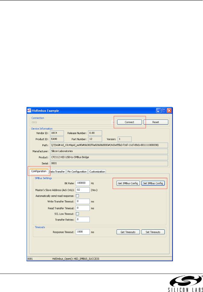
The HIDSMBus Example application uses the Windows CP2112 HID-to-SMBus DLL to transmit and receive data with the CP2112. The application also has access to the CP2112’s GPIO pins. The HIDSMBus Example application is installed as part of the CD installation process. Figure 2 shows a screenshot of the Windows Application. The following steps describe how to start the application and use some of its features.
1.Ensure that the hardware is connected to a Windows PC as shown in Figure 1. If the device is properly connected, the red SUSPEND LED on the CP2112 evaluation board will turn on.
2.Launch the HidSmbus Example application, which is found by clicking
Start All Programs Silicon Laboratories CP2112 Evaluation Kit HidSmbus Example.
3.In this application, you can configure the SMBus settings and GPIO pins, customize the device descriptors, and read/write data over the SMBus interface.
4.Select the appropriate device in the “Connection” drop down box and click Connect. After connecting to the device, you can configure the CP2112.
5.Figure 2 shows the Configuration tab, which allows you to get and set the SMBus configuration parameters. To set a parameter, modify the value that is in the corresponding text box or check/uncheck a box and click “Set SMBus Config”. To verify that the settings took place, click “Get SMBus Config”. These configuration parameters reset to their default values when the CP2112 is reset.
Figure 2. Configuration Tab
2 |
Rev. 0.2 |

CP2112-EK
6.Figure 3 shows the Data Transfer tab, which allows you to transfer read and write data over the SMBus.
7.To Read data from an SMBus device (non-addressed mode):
a.Enter the slave address in the “Read Request” box and the number of bytes to read. After this, click “Read Request” (shown in red).
b.To see the number of bytes that were read back, click “Get Read/Write Transfer Status”, and verify the number of bytes read at the bottom of the application (show in blue).
c.Next, click “Force Read Response” and then “Get Read Response” until you have read back the total number of bytes. The bytes will be shown in the “Received Data” field. The status of the CP2112 will be shown a the bottom of the PC app (shown in blue).
8.To read data from an EEPROM or similar device (addressed mode):
a.Enter the slave address in the “Addressed Read Request” box, the number of address bytes in the target address, the target address of the SMBus device being read (in hex), and the number of bytes to read. After this, click “Address Read Request” (shown in green).
b.To see the number of bytes that were read back, click Get Read/Write Transfer Status and verify the number of bytes read at the bottom of the application (show in blue).
c.Next, click “Force Read Response” and then “Get Read Response” until you have read back the total number of bytes. The bytes will be shown in the “Received Data” field. The status of the CP2112 will be shown a the bottom of the PC app (shown in blue).
9.To write data over the SMBus interface:
a.Enter the Slave address in the “Write Request” box and data (in hex) in the “Data to Write” box. After this, click “Write Request” (shown in purple).
b.Next, click Get Read/Write Transfer Status, and verify that the transfer was complete at the bottom of the application (shown in blue).
Figure 3. Data Transfer Tab
Rev. 0.2 |
3 |
Loading...