

Page 1
IP Communicator Series
Product Installation Document
PN 53109:I 4/26/2010 10-xxx
1 IPDACT - Internet Protocol Digital Alarm Communicator/ Transmitter
The IPDACT, IPDACT-2 and IPDACT-2UD are compact, Internet Protocol Digital Alarm Communicators/Transmitters
designed to allow FACP status communication to a Central Station via the internet. Using Contact ID protocol from the
FACP, the IPDACT Series convert the standard DACT phone communication to a protocol that can be transmitted and
received via the internet. They also check connectivity between the FACP and Central Station.
The IPDACT Series operate in conjunction with the VisorALARM receiver, located at the Central Station. The Visor
ALARM receives signals transmitted by the IPDACT Series over the internet, instead of the traditional public switched
telephone lines, and sends the signals through a serial port to automation software for processing.
The installer must determine whether the FACP has enough reserve auxiliary power (24 VDC nonresettable, filtered, regulated) to supply the IPDACT Series module. The following table lists the power requirements for each version of the
IPDACT.
IPDACT Model Alarm Current Standby Current
IPDACT 129 mA 100 mA
IPDACT-2 136 mA 93 mA
IPDACT-2UD 155 mA 98 mA
If the F ACP cannot supply sufficient auxiliary power , the IPDACT Series module requires an auxiliary power supply such
as the HP300ULX as described in Section 2.3.
NOTES:
1. Following installation, refer to the Quick Startup Guide, supplied with the IPDACT, for programming and
activation of the IPDACT Series on the internet.
2. Although not required, the FACP Secondary Phone Line may be connected to the Public Switched
Telephone Network (i.e. a POTS line) for backup reporting.
3. Installation and wiring of this device must be done in accordance with NFPA 70, 72 and local ordinances.
4. The IPDACT can only be used for commercial fire applications.
2 IPDACT Series Mounting/Wiring Options
There are several mounting options available for the IPDACT Series. The following sections describe these options. The
tables below are a guide for IPDACT Series mounting.
The following models are compatible with IPDACT Series Models.
Application (Power Source) Mounting Location Refer to Mounting Instruction Section
No Reserve Auxiliary Power HP300ULX Enclosure Section 2.3 on page 12
MS-9600(UD)LS FACP Enclosure Section 2.1.1 on page 4
MS-9200UD(E) IPENC Enclosure Section 2.2 on page 10
MS-9200UDLS(E) FACP Enclosure Section 2.1.1 on page 4
MS-9050UD FACP Enclosure Section 2.1.1 on page 4
MS-5UD-3(C)(E)
MS-10UD-7(C)(E)
2
MS-25
1
1
Table 1 IPDACT Series Mounting/Wiring Options
FACP Enclosure Section 2.1.1 on page 4
FACP Enclosure Section 2.1.1 on page 4
HP300ULX Enclosure
Section 2.3 on page 12
Page 2

Application (Power Source) Mounting Location Refer to Mounting Instruction Section
MS-25
2
IPENC Enclosure
Section 2.2 on page 10
FireWarden-100-2(E) FACP Enclosure Section 2.1.1 on page 4
FireWarden-100(E) IPENC Enclosure Section 2.2 on page 10
FireWarden-50 FACP Enclosure Section 2.1.1 on page 4
SFP-5UD(E)(R)
SFP-10UD(E)(R)
411(UD)
411UDAC
3
3
NFS2-3030(E)
NFS2-640(E)
4
NFS-320(E)(C)
NSP-25
NSP-25
NCA-2
XLS3000
XLS140-2
XLS-NCA2
IFC2-3030(E)
IFC2-640(E)
2
2
4
4
4
4
4
4
IFC-320(E)(C)
JNCA-2
4
1
1
4
4
4
FACP Enclosure Section 2.1.1 on page 4
FACP Enclosure Section 2.1.1 on page 4
HP300ULX Enclosure
HP300ULX Enclosure
FACP Enclosure (IPCHSKIT)
FACP Enclosure (IPCHSKIT)
IPENC Enclosure
HP300ULX Enclosure
IPENC Enclosure
FACP Enclosure (IPCHSKIT)
FACP Enclosure (IPCHSKIT)
FACP Enclosure (IPCHSKIT)
FACP Enclosure (IPCHSKIT)
FACP Enclosure (IPCHSKIT)
FACP Enclosure (IPCHSKIT)
IPENC Enclosure
FACP Enclosure (IPCHSKIT)
5
5
5
5
5
5
5
5
5
Section 2.4 on page 16
Section 2.3 on page 12
Section 2.1.2 on page 6
Section 2.1.2 on page 6
Section 2.2 on page 10
Section 2.3 on page 12
Section 2.2 on page 10
Section 2.1.2 on page 6
Section 2.1.2 on page 6
Section 2.1.2 on page 6
Section 2.1.2 on page 6
Section 2.1.2 on page 6
Section 2.1.2 on page 6
Section 2.2 on page 10
Section 2.1.2 on page 6
Unimode 200 Plus IPENC Enclosure Section 2.2 on page 10
Unimode 9050UD FACP Enclosure Section 2.1.1 on page 4
Unimode 5UD
Unimode 10UD
Unimode 640-2
ADT-NCA-2
IQ-636X-2(E)
IQ-318(E)(C)
AP-NCA-2
MICRO-320I(E)
E3 Series
GF505(W)
GF510(W)
GIF100
GIF100
5820XL
5820XL
7
5808
7
5808
1
1
4
4
4
4
4
4
6
1
1
2
2
7
7
IFP-2000 / IFP-2000VIP
IFP-2000 / IFP-2000VIP
IFP-1000 / IFP-1000VIP
IFP-1000 / IFP-1000VIP
IFP-100 / IFP-100VIP
IFP-100 / IFP-100VIP
IFP-50 / IFP-50VIP
7
7
2
7
7
7
7
FACP Enclosure Section 2.1.1 on page 4
FACP Enclosure Section 2.1.1 on page 4
FACP Enclosure (IPCHSKIT)
FACP Enclosure (IPCHSKIT)
FACP Enclosure (IPCHSKIT)
IPENC Enclosure
FACP Enclosure (IPCHSKIT)
IPENC Enclosure
IPENC Enclosure
5
5
5
5
Section 2.1.2 on page 6
Section 2.1.2 on page 6
Section 2.1.2 on page 6
Section 2.2 on page 10
Section 2.1.2 on page 6
Section 2.2 on page 10
Section 2.2 on page 10
FACP Enclosure Section 2.1.1 on page 4
FACP Enclosure Section 2.1.1 on page 4
HP300ULX Enclosure
IPENC Enclosure
HP300ULX Enclosure
IPENC Enclosure
HP300ULX Enclosure
IPENC Enclosure
HP300ULX Enclosure
IPENC Enclosure
HP300ULX Enclosure
IPENC Enclosure
HP300ULX Enclosure
IPENC Enclosure
HP300ULX Enclosure
Section 2.3 on page 12
Section 2.2 on page 10
Section 2.3 on page 12
Section 2.2 on page 10
Section 2.3 on page 12
Section 2.2 on page 10
Section 2.3 on page 12
Section 2.2 on page 10
Section 2.3 on page 12
Section 2.2 on page 10
Section 2.3 on page 12
Section 2.2 on page 10
Section 2.3 on page 12
Table 1 IPDACT Series Mounting/Wiring Options
2 IP Communicator Series Installation Document — P/N 53109:I 4/26/2010
Page 3

Application (Power Source) Mounting Location Refer to Mounting Instruction Section
IFP-50 / IFP-50VIP
2
5700
2
5700
2
5600
2
5600
2
5208
2
5208
2, 8
5104
2, 8
5104
2
IFP-25
2
IFP-25
2
IPENC Enclosure
HP300ULX Enclosure
IPENC Enclosure
HP300ULX Enclosure
IPENC Enclosure
HP300ULX Enclosure
IPENC Enclosure
HP300ULX Enclosure
IPENC Enclosure
HP300ULX Enclosure
IPENC Enclosure
Section 2.2 on page 10
Section 2.3 on page 12
Section 2.2 on page 10
Section 2.3 on page 12
Section 2.2 on page 10
Section 2.3 on page 12
Section 2.2 on page 10
Section 2.3 on page 12
Section 2.2 on page 10
Section 2.3 on page 12
Section 2.2 on page 10
Table 1 IPDACT Series Mounting/Wiring Options
1 The IPDACT is powered by the HP300ULX Power Supply only (not required for the IPDACT-2 and
IPDACT-2UD)
2 This panel is compatible with the IPDACT-2 model only.
3 Provides a complete communicator solution for any fire monitoring application.
4 Use of the UDACT Universal Digital Alarm Communicator/Transmitter is required for this
application. (For more information, see the UDACT Manual #50050.) This panel is only
compatible with the IPDACT-2 model.
5 If the system configuration does not support installation of the IPCHSKIT, use the IPENC enclosure.
6 Use of the DACT-E3 Digital Alarm Communicator/Transmitter is required for this application. (For
more information, see the DACT-E3 Installation Document #9000-0581.) This panel is only
compatible with the IPDACT-2 model.
7 This panel is compatible with the IPDACT-2 and IPDACT-2UD only.
8 This panel must be used with the HP300ULX Power Supply.
The following models are to be used with the IPDACT Series for retrofit applications only.
Application (Power Source) Mounting Location Refer to Mounting Instruction Section
MS-9600 IPENC Enclosure Section 2.2 on page 10
Unimode 9600 IPENC Enclosure Section 2.2 on page 10
MS-5024 IPENC Enclosure Section 2.2 on page 10
MS-5024UD IPENC Enclosure Section 2.2 on page 10
MS-5210UD IPENC Enclosure Section 2.2 on page 10
SFP-1024 IPENC Enclosure Section 2.2 on page 10
Unimode 5 IPENC Enclosure Section 2.2 on page 10
Unimode 10 IPENC Enclosure Section 2.2 on page 10
NFS-3030(E)
NFS-640(E)
1
NCA
1
1
AM2020/AFP-1010
System 5000(C)
System 500(C)
AFP-300/400
AFP-200(C)
AFP-100(E)
XLS140
1
XLS-NCA
IFC-640(E)
1
JNCA
IFC-2020/1010
1
1
1
1
1
1
1
1
FACP Enclosure (IPCHSKIT)
FACP Enclosure (IPCHSKIT)
FACP Enclosure (IPCHSKIT)
1
FACP Enclosure (IPCHSKIT)
FACP Enclosure (IPCHSKIT)
FACP Enclosure (IPCHSKIT)
FACP Enclosure (IPCHSKIT)
IPENC Enclosure
IPENC Enclosure
FACP Enclosure (IPCHSKIT)
FACP Enclosure (IPCHSKIT)
FACP Enclosure (IPCHSKIT)
FACP Enclosure (IPCHSKIT)
FACP Enclosure (IPCHSKIT)
2
2
2
2
2
2
2
Section 2.1.2 on page 6
Section 2.1.2 on page 6
Section 2.1.2 on page 6
Section 2.1.2 on page 6
Section 2.1.2 on page 6
Section 2.1.2 on page 6
Section 2.1.2 on page 6
Section 2.2 on page 10
Section 2.2 on page 10
2
2
2
2
2
Section 2.1.2 on page 6
Section 2.1.2 on page 6
Section 2.1.2 on page 6
Section 2.1.2 on page 6
Section 2.1.2 on page 6
Table 2 IPDACT Series Mounting/Wiring Options for Retrofit Applications
IP Communicator Series Installation Document — P/N 53109:I 4/26/2010 3
Page 4

Application (Power Source) Mounting Location Refer to Mounting Instruction Section
IFC-400
IFC-200(E)
Unimode 640
ADT-NCA
Unimode 300/400
1
1
1
1
1
Unimode 2020/1010
IQ-636X(E)
ANSUL-NCA
IQ-396X
IQ-301(E)
MICRO-640I(E)
MICRO-NCA
MICRO-300I/400I
MICRO-200I
1
1
1
1
1
1
1
1
FACP Enclosure (IPCHSKIT)
IPENC Enclosure
FACP Enclosure (IPCHSKIT)
FACP Enclosure (IPCHSKIT)
FACP Enclosure (IPCHSKIT)
1
FACP Enclosure (IPCHSKIT)
FACP Enclosure (IPCHSKIT)
FACP Enclosure (IPCHSKIT)
FACP Enclosure (IPCHSKIT)
IPENC Enclosure
FACP Enclosure (IPCHSKIT)
FACP Enclosure (IPCHSKIT)
FACP Enclosure (IPCHSKIT)
IPENC Enclosure
2
Section 2.1.2 on page 6
Section 2.2 on page 10
2
2
2
2
2
2
2
Section 2.1.2 on page 6
Section 2.1.2 on page 6
Section 2.1.2 on page 6
Section 2.1.2 on page 6
Section 2.1.2 on page 6
Section 2.1.2 on page 6
Section 2.1.2 on page 6
Section 2.2 on page 10
2
2
2
Section 2.1.2 on page 6
Section 2.1.2 on page 6
Section 2.1.2 on page 6
Section 2.2 on page 10
Table 2 IPDACT Series Mounting/Wiring Options for Retrofit Applications
1 Use of the UDACT Universal Digital Alarm Communicator/Transmitter is required for this
application. (For more information, see the UDACT Manual #50050.) This panel is only
compatible with the IPDACT-2 model.
2 If the system configuration does not support installation of the IPCHSKIT, use the IPENC enclosure.
2.1 Mounting IPDACT Series in the Fire Alarm Control Panel Enclosure
Install the IPDACT Series in the FACP backbox using the IPBRKT bracket or the IPCHSKIT, as described below.
2.1.1 IPBRKT Bracket Installation
1. Position the two tabs in the IPBRKT bracket over the two embossed protrusions in lower left corner of the backbox
and slide the bracket down with tabs going under embossed protrusions as illustrated in Figure 1.
Backbox
backbox
tab
IPBRKT bracket
tab
embossed
protrusion
backbox
embossed
protrusion
Figure 1 IPBRKT Installation
IPBRKTinstall1a.wmf
4 IP Communicator Series Installation Document — P/N 53109:I 4/26/2010
Page 5
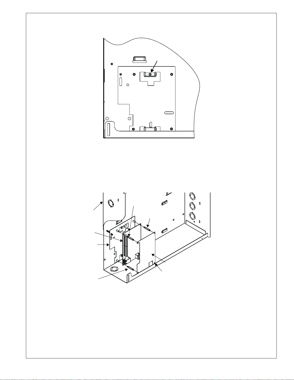
2. Secure the IPBRKT bracket to the backbox by installing the supplied screw into the top tab as illustrated in Figure 2.
The screw will feed through hole in emboss and self-thread into bracket hole.
Backbox
screw
IPBRKT bracket
Figure 2 IPBRKT Installation
3. Secure IPDACT Module to IPBRKT bracket using the four supplied standoffs as illustrated in Figure 3.
4. Wire the IPDACT as described in the following sections of this document.
5. Attach the label/cover to the IPDACT by pressing it onto the four standoffs installed in step 3.
IPBRKTinstall2a.wmf
FACP backbox
IPDACT module
IPBRKT bracket
standoff
standoff
standoff (not used for
IPDACT-2 or IPDACT-2UD)
label/cover
standoff
IPBRKTinstall3a.wmf
Figure 3 IPBRKT Installation
IP Communicator Series Installation Document — P/N 53109:I 4/26/2010 5
Page 6

2.1.2 IPCHSKIT (Chassis) Installation
1. Secure the IPDACT Module to the IPCHSKIT mounting plate using the four supplied standoffs as illustrated in
Figure 4.
2. Install the IPCHSKIT mounting plate into the chassis and secure with the supplied screws. (For specific chassis
installations, refer to the IPCHSKIT Installation Document #53294.)
3. Wire the IPDACT as described in the following sections of this document.
4. Attach the polycarbonate cover with label to the IPDACT by pressing it onto the four standoffs installed in step 1.
2 screw locations
IPCHSKIT mounting plate
standoffs
IPDACT Module
2 screw locations
(underneath)
polycarbonate cover with label
ipchskit.wmf
Figure 4 IPCHSKIT Installation
6 IP Communicator Series Installation Document — P/N 53109:I 4/26/2010
Page 7

Wiring the IPDACT Series Within the Fire Alarm Control Panel Enclosure
.
”
Figure 5 and Figure 6 detail the connections that must be made between the IPDACT Series and the FACP.
RJ45 Connector for connection to RS232 serial port.
Use a Serial to USB converter if the computer does not have an RS232 port.
(FOR PROGRAMMING USE ONLY)
(minimum wire
gauge 22-14 Awg)
Supplied Phone Cable
Supplied Phone Cable
(Note the the male plug connectors on the other end of the Supplied Phone
Cable, plug into the Primary and Secondary Phone Jacks on the FACP DACT.)
(minimum wire gauge 18-14 Awg)
Ferrite* Ferrite*
From FACP Nonresettable 24VDC (-)
From FACP Nonresettable 24VDC (+)
(factory
installed)
1KΩ ELR
Figure 5 IPDACT Wiring
ipdactbrd.wmf
RJ45 Connector for connection to
Ethernet/Internet (minimum wire
gauge 24-22 Awg)
* Refer to Figure 7 for Ferrite Bead Installation
The smaller ferrite bead is used on the “TO AP
connection.
The larger ferrite bead is used on the “24VDC”
connection.
IP Communicator Series Installation Document — P/N 53109:I 4/26/2010 7
Page 8

2UD Modem Card
n
P
”
RJ45 Connector for connection to RS232 serial port.
Use a Serial to USB converter if the computer does not have an RS232 port.
(FOR PROGRAMMING USE ONLY)
(minimum wire
gauge 22-14 Awg)
Supplied Phone Cable
Supplied Phone Cable
(Note the the male plug connectors on the other end of the Supplied Phone
Cable, plug into the Primary and Secondary Phone Jacks on the FACP DACT.)
(minimum wire gauge 18-14 Awg)
Ferrite*
1KΩ ELRs
(factory installed)
From FACP Nonresettable 24VDC (-)
From FACP Nonresettable 24VDC (+)
Ferrite*
RJ45 Connector for connection to
Ethernet/Internet (minimum wire
gauge 24-22 Awg)
* Refer to Figure 7 for Ferrite Bead Installatio
The smaller ferrite bead is used on the “TO A
connection.
The larger ferrite bead is used on the “24VDC
connection.
Figure 6 IPDACT-2 and IPDACT-2UD Wiring
Ferrite Bead Installation
A Ferrite Bead is required for the TO AP (smaller bead) to FACP Telco Line wires and for the IPDACT Series 24 VDC
(larger bead) Power Supply wires. Each wire must be wrapped twice around the Ferrite Bead at the end closest to
IPDACT Series board.
Note that the following illustration depicts one wire wrapped around the Ferrite Bead. The two wir es to the T O AP terminals must be wrapped around one, smaller Ferrite Bead and the -24 VDC and + 24 VDC wires must be wrapped around a
second, larger Ferrite Bead.
ipdact-2brd_2UD.wmf
ferriteipdact.wmf
Figure 7 Ferrite Bead Installation
8 IP Communicator Series Installation Document — P/N 53109:I 4/26/2010
Page 9

2UD Modem Card Installation
The IPDACT-2 can be converted to an IPDACT-2UD by installing the 2UD Modem Card. This will provide upload/
download capabilities.
WARNING: DISCONNECT POWER
!
BEFORE PROCEEDING WITH THE INSTALLATION, MAKE SURE ALL POWER (AC AND DC) HAS BEEN
REMOVED.
1. Remove the plastic label/cover from the IPDACT-2 Module.
2. Remove the jumpers from A and B pins located in the upper left portion of the IPDACT-2 module.
3. Carefully align the connector on the 2UD Modem Card with the connector located in the top left of the IPDACT-2
module and align the A and B connectors on the 2UD Modem Card with the A and B pins on the IPDACT-2 module
(jumpers removed in step 2).
4. Carefully press the 2UD Modem Card onto the IPDACT-2 module connectors. Ensure that the 2UD Modem Card is
securely seated, being careful not to bend or break any pins on the connectors.
5. Reinstall the plastic label/cover on the IPDACT-2UD Module.
6. Reapply all power (AC and DC) and test the system for proper operation.
Plug 2UD Modem Card into
IPDACT-2 (steps 3 and 4)
Remove jumpers from
A and B pins (step 2)
2UD Modem Card
ipdact-2brd.wmf
2UDbrd.wmf
Figure 8 2UD Modem Installation
Plug A and B connectors on
Modem Card into A and B pins
on IPDACT-2 (steps 3 and 4)
IPDACT-2 Module
IP Communicator Series Installation Document — P/N 53109:I 4/26/2010 9
Page 10

2.2 Mounting the IPDACT Series in the IPENC Enclosure
The IPDACT Series mounts to the factory-installed bracket inside the IPENC enclosure.
1. Secure IPDACT Series Module to the bracket using the four supplied screws as illustrated in Figure 9.
2. Wire the IPDACT Series as described in the following sections of this document.
3. Close the IPENC door and secure it to the enclosure with four supplied screws in locations indicated.
mounting
screws
door
screw
IPDACT Module
IPENC Enclosure
door screw
door
screws
IPDACT-ENCFmount1a.wmf
Figure 9 IPENC Installation
10 IP Communicator Series Installation Document — P/N 53109:I 4/26/2010
Page 11

Wiring the IP Communicator to the Fire Alarm Control Panel (refer to Figures 10 and 11)
1. Remove all power (AC and DC) from the FACP before installing any wires.
2. All wiring between the FACP and IPDACT Series must be in metal conduit which is no more than 6” in length. (The
IPDACT Series must be installed within the same room as the FACP).
3. Connect one end of the supplied phone line cable to the Primary and Secondary Phone Line connectors on the FACP
by inserting the male plugs into the RJ45 connectors.
4. Wire the other end of the supplied phone line cable to the TO AP terminals as illustrated in Figures 5, 6, 10 and 11 of
this document.
NOTE: Tip & Ring wire connections for TO AP terminal are interchangeable.
5. Connect Nonresettable 24 VDC power from the FACP to the power terminals on the IPDACT Series.
6. Connect the RJ45 connector on the IPDACT Series to an Ethernet/Internet connector.
7. Refer to the appropriate FACP manual for power specifications and wiring details and to Figures 5 and 6 in this
document for IPDACT connection details.
8. Reapply all power (AC and DC) which was removed in step 1.
FACP
Main Circuit Board
FACP Backbox
Primary
Phone Line
Secondary
Phone Line
24 VDC*
metal conduit (6” max. when
using the supplied phone
cables). Longer distances (up
to 20’ within the same room)
supplemental phone cables
†
†
is acceptable when
are used.
*FACP Power Supply requirements- refer to the table
on page 1 for each version of the IPDACT Series.
†
Refer to Tables 1 and 2 for applications where the phone lines
must be connected to an installed UDACT/DACT-E3.
Figure 10 IPDACT Connections to FACP
IPDACT
to APto AP
IPENC
Enclosure
IP-ENCFtoFACP2a.wmf
RJ45
Ethernet/
Internet
Connection
IP Communicator Series Installation Document — P/N 53109:I 4/26/2010 11
Page 12

FACP
Main Circuit Board
Primary
Phone Line
IP2UD-ENCFtoFACP2a.wmf
†
IPDACT-2(UD)
FACP Backbox
24 VDC*
Secondary
Phone Line
metal conduit (6” max. when
using the supplied phone
cables). Longer distances (up
to 20’ within the same room)
supplemental phone cables
†
is acceptable when
are used.
*FACP Power Supply requirements- refer to the table
on page 1 for each version of the IPDACT Series.
†
Refer to Tables 1 and 2 for applications where the phone lines
must be connected to an installed UDACT/DACT-E3.=
to AP
to AP
IPENC
Enclosure
RJ45
Ethernet/
Internet
Connection
Figure 11 IPDACT-2 and IPDACT-2UD Connections to FACP
2.3 Mounting the IPDACT in the HP300ULX Power Supply Enclosure
The IPDACT Series can be mounted inside the HP300ULX power supply enclosure as described below.
1. Position the IPBRKT bracket mounting hole and slot over the two mounting holes in the HP300ULX backbox. Use
the landmarks illustrated in Figure 12 to locate the correct mounting location.
2. Secure the IPBRKT bracket to the backbox by installing the supplied screws into the top left hole and bot tom right
slot of the IPBRKT as illustrated, and tighten.
HP300ULXinstall1.wmf
IPBRKT
screw
Bracket
Figure 12 HP300ULX Installation
12 IP Communicator Series Installation Document — P/N 53109:I 4/26/2010
Page 13

3. Attach the four supplied 0.75” M/F standoffs to the IPBRKT as shown in Figure 13.
4. Then, secure the IPDACT Series Module to the IPBRKT using the four supplied M/M standoffs (three for IPDACT-2
and IPDACT-2UD).
5. Wire the IPDACT Series as described in the following sections of this document.
6. Attach the polycarbonate cover with label by pressing it onto the four standoffs installed in step 4.
standoff
IPBRKT bracket
M/F standoff
IPDACT Module
M/F standoff
standoff
M/F standoff (not used for IPDACT-2 or IPDACT-2UD)
standoff (not used for IPDACT-2 or IPDACT-2UD)
polycarbonate cover with label
standoff
Figure 13 IPDACT Series Mounting in HP300ULX
Wiring the IPDACT Series to the HP300ULX Power Supply and FACP Note: If a 411UD is also installed, refer to for details on wiring both units.
Refer to Figure 14 on page 14 (IPDACT) or Fi gure 15 on page 15 (IPDACT-2/UD) for an illustration of the following
wiring details.
1. Connect the AC power terminals of the FACP and HP300ULX Power Supply to the same AC power main feed. A
loss of AC power will cause the FACP to generate an AC Power Loss indication which will be recognized as an AC
power loss for both panels.
2. The phone lines between the FACP and IPDACT Series, which is mounted in the HP300ULX backbox, must be in
conduit. (The IPDACT Series must be installed in the same room as the FACP).
3. Connect one end of the supplied phone line cable to the Primary and Secondary Phone Line connectors on the FACP
by inserting the male plugs into the RJ45 connectors.
4. Wire the other end of the supplied phone line cable to the TO AP terminals of the IPDACT Series as illustrated in
Figure 14 (IPDACT) or Figure 15 (IPDACT-2/UD) on the following pages and in Figures 5 or 6 of this document.
HP300ULXinstall3.wmf
NOTE: Tip & Ring wire connections for TO AP terminal are interchangeable.
5. Connect Nonresettable 24 VDC power from the HP300ULX to the power terminals on the IPDACT Series as
illustrated in Figure 14 (IPDACT) or Figure 15 (IPDACT-2/UD).
6. Connect one wire from the Battery Fail NO (Normally Open) contact of the HP300ULX to one of the Input
terminals on the IPDACT Series and a second wire from the Battery Fail C (Common) contact of the HP300ULX to
the other Input terminal on the IPDACT Series. This will allow the IPDACT Series auxiliary trouble input terminals
to monitor for an HP300ULX battery failure.
7. Install a 1KΩ ELR across the Battery Fail NO (Normally Open) contact and the C (Common) contact to allow the
IPDACT Series to supervise the wiring.
8. Connect the RJ45 connector on the IPDACT Series to an Ethernet/Internet connector.
9. Refer to the appropriate FACP manual for power specifications and wiring details and to Figures 5 or 6 in this
document for IPDACT connection details.
IP Communicator Series Installation Document — P/N 53109:I 4/26/2010 13
Page 14

HP300ULXitoFACP90x2a.wmf
RJ45
Ethernet/
Internet
Connection
HP300ULX Power Supply Enclosure
must be
(The IPDACT
installed in the
the FACP.)
same room as
FACP
Main Circuit Board
Primary
Phone Line
Seondary
Phone Line
metal conduit (6” max.
when using the supplied
acceptable when
the same room) is
phone cables). Longer
distances (up to 20’ within
FACP Backbox
supplemental phone cables
are used.
* The FACP and HP300ULX Power Supply must be connected to the same AC main circuit.
This will allow the FACP to transmit an AC fail signal upon AC loss for both panels.
AC Power*
Figure 14 Wiring IPDACT to HP300ULX and FACP
14 IP Communicator Series Installation Document — P/N 53109:I 4/26/2010
Page 15

IPDACT-2UDHP300ULXitoFACP90x2a.wmf
RJ45
Ethernet/
Internet
Connection
HP300ULX Power Supply Enclosure
FACP
Main Circuit Board
Primary
Phone Line
Secondary
Phone Line
are used.
acceptable when
metal conduit (6” max.
the same room) is
phone cables). Longer
when using the supplied
distances (up to 20’ within
supplemental phone cables
FACP Backbox
* The FACP and HP300ULX Power Supply must be connected to the same AC main circuit.
This will allow the FACP to transmit an AC fail signal upon AC loss for both panels.
AC Power*
Figure 15 Wiring IPDACT-2 and IPDACT-2UD to HP300ULX and FACP
IP Communicator Series Installation Document — P/N 53109:I 4/26/2010 15
Page 16

2.4 Mounting 411 or 411UD in HP300ULX Power Supply Enclosure with
IPDACT Series
The 411/411UD can be mounted inside the HP300ULX power supply enclosure as described below.
1. Position the two mounting tabs on the 411/411UD, over the two mounting holes in the HP300ULX backbox. Use
dimensions and the landmarks illustrated in Figure 16 to locate the correct mounting location.
411/411UD
mounting
holes
Figure 16 411/411UD Installation
2. Secure the 411/411UD to the backbox by installing the supplied screws into the top and bottom mounting tabs of the
411/411UD and tighten. Refer to Figure 17.
mounting tab
411/411UD DACT
mounting tab
HP300ULXinstall411UD.wmf
HP300ULXinstall411UD2a.wmf
Figure 17 411/411UD Installation
3. Install the IPDACT Series in the HP300ULX enclosure as described in Section 2.3 of this document.
16 IP Communicator Series Installation Document — P/N 53109:I 4/26/2010
Page 17

Wiring 411 or 411UD and IPDACT Series to the HP300ULX Power Supply and FACP
Refer to Figure 18 on page 18 (IPDACT) or Figure 19 on page 19 (IPDACT-2/UD) for wiring details.
1. Connect the AC power terminals of the FACP and HP300ULX Power Supply to the same AC power main feed. A
loss of AC power will cause the 411/411UD to generate an AC Power Loss indication which will be recognized as an
AC power loss for both panels.
2. Connect one end of the supplied phone cable to the Primary and Secondary Telco Jack on the 411/411UD.
3. Wire the other end of the supplied phone line cable to the TO AP terminals of the IPDACT Series as illustrated in
Figure 18 on page 18 for the IPDACT or Figure 19 on page 19 for the IPDACT -2 and IPDACT-2UD and in Figures 5
or 6 of this document.
NOTE: Tip & Ring wire connections for TO AP terminal are interchangeable.
4. Connect Nonresettable 24 VDC power from the HP300ULX to the power terminals on the IPDACT and to the power
terminals on the 411/411UD as illustrated in Figure 18 or Figure 19.
5. Connect one wire from the Battery Fail NO (Normally Open) contact of the HP300ULX to one of the Input
terminals on the IPDACT Series and a second wire from the Battery Fail C (Common) contact of the HP300ULX to
the other Input terminal on the IPDACT Series. This will allow the IPDACT auxiliary trouble input terminals to
monitor for an HP300ULX battery failure.
6. Install a 1KΩ ELR across the Battery Fail NO (Normally Open) contact and the C (Common) contact to allow the
IPDACT Series to supervise the wiring.
7. Connect the RJ45 connector on the IPDACT Series to an Ethernet/Internet connector.
8. For the 411UD only, connect one wire from the AC Fail NO (Normally Open) contact of the HP300ULX to one of
the Channel 4 Input terminals on the 411UD and a second wire from the AC Fail C (Common) contact of the
HP300ULX to the other Channel 4 Input terminal on the 411UD. Program the 411UD Input Channel 4 to monitor for
an HP300ULX AC failure (factory default).
9. For the 411UD only, install a 2.2KΩ ELR across the AC Fail NO (Normally Open) contact and the C (Common)
contact to allow the 411UD to supervise the wiring.
10. Connect a pair of wires from the Channel 1 Input terminals on the 411/411UD to the FACP Al arm Relay C
(Common) and NO (Normally Open) Contacts and program the 411/411UD Channel 1 to monitor for alarms.
11. Install a 2.2KΩ ELR across the FACP Alarm Relay C (Common) and NO (Normally Open) contacts to allow the
411/411UD to supervise the wiring.
12. Connect a pair of wires from the Channel 2 Input terminals on the 411/411UD to the FACP Trouble Relay C
(Common) and NO (Normally Open) Contacts and program the 411/411UD Channel 1 to monitor for troubles.
13. Install a 2.2KΩ ELR across the FACP Trouble Relay C (Common) and NO (Normally Open) contacts to allow the
411/411UD to supervise the wiring.
14. Connect a pair of wires from the Channel 3 Input terminals on the 411/411UD to the FACP Supervisory Relay C
(Common) and NO (Normally Open) Contacts and program the 411/411UD Channel 1 to monitor for supervisory
conditions.
15. Install a 2.2KΩ ELR across the FACP Supervisory Relay C (Common) and NO (Normally Open) contacts to allow
the 411/411UD to supervise the wiring.
16. Connect a pair of wires between the NO (Normally Open) and C (Common)
an addressable monitor module on the FACP SLC Loop. Program the module to monitor for 411/411UD
communicator fault.
17. Refer to the appropriate FACP manual for power specifications and wiring details.
Trouble Relay on the 411/411UD and
IP Communicator Series Installation Document — P/N 53109:I 4/26/2010 17
Page 18

To Alarm,
Trouble,
Supervisory
Output Relays
on FACP
(2.2KΩ ELRs at
FACP)
Communicator
Fault to monitor
module on
FACP SLC
Loop
HP300ULXto411UD2.wmf
RJ45
Ethernet/
Internet
Connection
Figure 18 Wiring IPDACT to 411/411UD and HP300ULX
NOTE: When using a 411, AC Loss is reported from the FACP Trouble Relay output to the 41 1 Trouble Input.
The 411 does not have a 4th Input Channel. The 411 does allow any of the three Input Channels to be
programmed to report AC loss if desired.
18 IP Communicator Series Installation Document — P/N 53109:I 4/26/2010
Page 19

To Alarm,
Trouble,
Supervisory
Output Relays
on FACP
(2.2KΩ ELRs at
FACP)
Communicator
Fault to monitor
module on
FACP SLC
Loop
IPDACT-2UDHP300ULXto411UD2.wmf
RJ45
Ethernet/
Internet
Connection
Figure 19 Wiring IPDACT-2 or IPDACT-2UD to 411/411UD and HP300ULX
NOTE: When using a 411, AC Loss is reported from the FACP Trouble Relay output to the 41 1 Trouble Input.
The 411 does not have a 4th Input Channel. The 411 does allow any of the three Input Channels to be
programmed to report AC loss if desired.
IP Communicator Series Installation Document — P/N 53109:I 4/26/2010 19
 Loading...